WO2015115251A1 - Dispositif de climatisation - Google Patents
Dispositif de climatisation Download PDFInfo
- Publication number
- WO2015115251A1 WO2015115251A1 PCT/JP2015/051405 JP2015051405W WO2015115251A1 WO 2015115251 A1 WO2015115251 A1 WO 2015115251A1 JP 2015051405 W JP2015051405 W JP 2015051405W WO 2015115251 A1 WO2015115251 A1 WO 2015115251A1
- Authority
- WO
- WIPO (PCT)
- Prior art keywords
- indoor
- air volume
- air
- temperature
- fans
- Prior art date
Links
Images


Classifications
-
- F—MECHANICAL ENGINEERING; LIGHTING; HEATING; WEAPONS; BLASTING
- F24—HEATING; RANGES; VENTILATING
- F24F—AIR-CONDITIONING; AIR-HUMIDIFICATION; VENTILATION; USE OF AIR CURRENTS FOR SCREENING
- F24F11/00—Control or safety arrangements
- F24F11/70—Control systems characterised by their outputs; Constructional details thereof
- F24F11/72—Control systems characterised by their outputs; Constructional details thereof for controlling the supply of treated air, e.g. its pressure
- F24F11/74—Control systems characterised by their outputs; Constructional details thereof for controlling the supply of treated air, e.g. its pressure for controlling air flow rate or air velocity
- F24F11/77—Control systems characterised by their outputs; Constructional details thereof for controlling the supply of treated air, e.g. its pressure for controlling air flow rate or air velocity by controlling the speed of ventilators
-
- F—MECHANICAL ENGINEERING; LIGHTING; HEATING; WEAPONS; BLASTING
- F24—HEATING; RANGES; VENTILATING
- F24F—AIR-CONDITIONING; AIR-HUMIDIFICATION; VENTILATION; USE OF AIR CURRENTS FOR SCREENING
- F24F1/00—Room units for air-conditioning, e.g. separate or self-contained units or units receiving primary air from a central station
- F24F1/0003—Room units for air-conditioning, e.g. separate or self-contained units or units receiving primary air from a central station characterised by a split arrangement, wherein parts of the air-conditioning system, e.g. evaporator and condenser, are in separately located units
-
- F—MECHANICAL ENGINEERING; LIGHTING; HEATING; WEAPONS; BLASTING
- F24—HEATING; RANGES; VENTILATING
- F24F—AIR-CONDITIONING; AIR-HUMIDIFICATION; VENTILATION; USE OF AIR CURRENTS FOR SCREENING
- F24F11/00—Control or safety arrangements
- F24F11/70—Control systems characterised by their outputs; Constructional details thereof
- F24F11/72—Control systems characterised by their outputs; Constructional details thereof for controlling the supply of treated air, e.g. its pressure
- F24F11/74—Control systems characterised by their outputs; Constructional details thereof for controlling the supply of treated air, e.g. its pressure for controlling air flow rate or air velocity
- F24F11/76—Control systems characterised by their outputs; Constructional details thereof for controlling the supply of treated air, e.g. its pressure for controlling air flow rate or air velocity by means responsive to temperature, e.g. bimetal springs
-
- F—MECHANICAL ENGINEERING; LIGHTING; HEATING; WEAPONS; BLASTING
- F24—HEATING; RANGES; VENTILATING
- F24F—AIR-CONDITIONING; AIR-HUMIDIFICATION; VENTILATION; USE OF AIR CURRENTS FOR SCREENING
- F24F11/00—Control or safety arrangements
- F24F11/30—Control or safety arrangements for purposes related to the operation of the system, e.g. for safety or monitoring
- F24F11/46—Improving electric energy efficiency or saving
-
- F—MECHANICAL ENGINEERING; LIGHTING; HEATING; WEAPONS; BLASTING
- F24—HEATING; RANGES; VENTILATING
- F24F—AIR-CONDITIONING; AIR-HUMIDIFICATION; VENTILATION; USE OF AIR CURRENTS FOR SCREENING
- F24F2110/00—Control inputs relating to air properties
- F24F2110/10—Temperature
- F24F2110/12—Temperature of the outside air
-
- Y—GENERAL TAGGING OF NEW TECHNOLOGICAL DEVELOPMENTS; GENERAL TAGGING OF CROSS-SECTIONAL TECHNOLOGIES SPANNING OVER SEVERAL SECTIONS OF THE IPC; TECHNICAL SUBJECTS COVERED BY FORMER USPC CROSS-REFERENCE ART COLLECTIONS [XRACs] AND DIGESTS
- Y02—TECHNOLOGIES OR APPLICATIONS FOR MITIGATION OR ADAPTATION AGAINST CLIMATE CHANGE
- Y02B—CLIMATE CHANGE MITIGATION TECHNOLOGIES RELATED TO BUILDINGS, e.g. HOUSING, HOUSE APPLIANCES OR RELATED END-USER APPLICATIONS
- Y02B30/00—Energy efficient heating, ventilation or air conditioning [HVAC]
- Y02B30/70—Efficient control or regulation technologies, e.g. for control of refrigerant flow, motor or heating
Definitions
- the present invention relates to an air conditioner, and more particularly to an air conditioner capable of manually instructing the air volume setting of an indoor fan.
- An object of the present invention is to reduce wasteful power consumption of an indoor fan and improve APF in an air conditioner capable of manually instructing the air volume setting of the indoor fan.
- the air conditioner according to the first aspect includes an outdoor unit and an indoor unit having an indoor heat exchanger and an indoor fan, and is an air conditioner capable of manually instructing the air volume setting of the indoor fan.
- indoor air volume restriction control is performed to forcibly limit the air volume setting of the indoor fan to the low air volume side according to the outside air temperature in a state where the air volume setting of the indoor fan is manually instructed.
- the indoor air volume restriction control is performed in the state where the indoor fan air volume setting is manually instructed, so that when the indoor fan air volume is unnecessarily large when viewed from the outside air temperature, The fan air volume can be forcibly reduced.
- An air conditioner according to a second aspect is the air conditioner according to the first aspect, wherein the outdoor unit or the indoor unit has an indoor flow rate adjustment valve that adjusts the flow rate of the refrigerant flowing through the indoor heat exchanger.
- the opening of the indoor flow rate control valve is equal to or less than the air volume restriction permission opening, the indoor air volume restriction control is performed.
- the indoor air conditioning load is large, restricting the indoor fan air volume setting to the low air volume side will process the indoor air conditioning load even if the air volume of the indoor fan is large when viewed from the outside air temperature. In this case, it is not preferable to perform the indoor air volume restriction control.
- the indoor air conditioning load is large, the flow rate of the refrigerant flowing through the indoor heat exchanger tends to increase.
- whether or not the indoor air conditioning load is large is determined based on the opening of the indoor flow rate control valve that increases as the flow rate of the refrigerant flowing through the indoor heat exchanger increases. ing.
- the indoor air volume restriction control can be appropriately performed in consideration of not only the outside air temperature but also the indoor air conditioning load.
- An air conditioner according to a third aspect is the air conditioner according to the first or second aspect, wherein an upper air volume upper limit of the indoor fan that can be changed according to the outside air temperature is provided, and the upper air volume upper limit of the indoor fan is reduced. To control indoor air volume restriction.
- the air conditioner according to the fourth aspect is the air conditioner according to the third aspect, wherein the air volume upper limit of the indoor fan is decreased according to the decrease in the outside air temperature during the cooling operation and / or during the heating operation.
- the upper limit of the air volume of the indoor fan is lowered according to the increase in the outside air temperature.
- the indoor air volume restriction control is performed by setting the upper air volume limit of the indoor fan
- the air volume setting of the indoor fan that is manually instructed is higher than the upper air volume limit.
- the air volume setting of the indoor fan can be forcibly reduced to the air volume upper limit.
- the air volume setting of the indoor fan instructed manually is an air volume below the upper limit of the air volume
- the air volume setting of the indoor fan can be maintained with the air volume setting of the indoor fan instructed manually.
- the indoor air volume restriction control can be performed while maintaining the manually instructed indoor fan air volume setting as much as possible.
- the air volume setting of the indoor fan is set to the low air volume side. Relax restrictions.
- the indoor air volume restriction control When the indoor air volume restriction control is performed, if the operating condition changes such as an increase in the air conditioning load in the room, the indoor temperature may deviate from the target indoor temperature. It is not preferable to keep it excessively restricted to the low air volume side.
- the indoor air volume restriction control can be appropriately performed here in consideration of not only the outside air temperature but also the indoor temperature change.
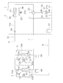
- FIG. 1 is a schematic configuration diagram of an air conditioner 1 according to an embodiment of the present invention.
- the air conditioning apparatus 1 is an apparatus used for air conditioning indoors such as buildings by performing a vapor compression refrigeration cycle operation.
- the air conditioner 1 is mainly configured by connecting an outdoor unit 2 and a plurality (here, two) of indoor units 4 and 5.
- the outdoor unit 2 and the plurality of indoor units 4 and 5 are connected via a liquid refrigerant communication tube 6 and a gas refrigerant communication tube 7.
- the vapor compression refrigerant circuit 10 of the air conditioner 1 is configured by connecting the outdoor unit 2 and the plurality of indoor units 4 and 5 via the refrigerant communication pipes 6 and 7.
- the indoor units 4 and 5 are installed indoors.
- the indoor units 4 and 5 are connected to the outdoor unit 2 through the refrigerant communication pipes 6 and 7 and constitute a part of the refrigerant circuit 10.
- the configuration of the indoor units 4 and 5 will be described. Since the indoor unit 5 has the same configuration as that of the indoor unit 4, only the configuration of the indoor unit 4 will be described here.
- the configuration of the indoor unit 5 is indicated by reference numerals indicating the respective parts of the indoor unit 4. The description will be omitted by replacing the number base with the number 50.
- the indoor unit 4 mainly has an indoor refrigerant circuit 10a (in the indoor unit 5, the indoor refrigerant circuit 10b) that constitutes a part of the refrigerant circuit 10.
- the indoor refrigerant circuit 10a mainly includes an indoor expansion valve 41 and an indoor heat exchanger 42.
- the indoor expansion valve 41 is an indoor flow rate adjusting valve that adjusts the flow rate of the refrigerant by reducing the pressure of the refrigerant flowing through the indoor refrigerant circuit 10a.
- the indoor expansion valve 41 is an electric expansion valve connected to the liquid side of the indoor heat exchanger 42.
- the indoor heat exchanger 42 includes, for example, a cross fin type fin-and-tube heat exchanger.
- An indoor fan 43 for sending indoor air to the indoor heat exchanger 42 is provided in the vicinity of the indoor heat exchanger 42. By blowing indoor air to the indoor heat exchanger 42 by the indoor fan 43, the indoor heat exchanger 42 performs heat exchange between the refrigerant and the indoor air.
- the indoor fan 43 is rotationally driven by an indoor fan motor 43a. Accordingly, the indoor heat exchanger 42 functions as a refrigerant radiator or a refrigerant evaporator.
- the indoor fan motor 43a can vary the air volume of the indoor fan 43 by changing the number of rotations.
- the air volume of the indoor fan 43 is changed by changing the rotation speed of the indoor fan motor 43a, so that the air volume H having the largest rotation speed and the large air volume H, the air volume M having a medium air volume smaller than the rotation speed of the air volume H, It can be changed in four stages between an air volume L of a small air volume that is much smaller than the rotational speed of the air volume M, and an air volume LL of a minimum air volume that is smaller than the rotational speed of the air volume L.
- the three air volume settings of the air volume H, the air volume M, and the air volume L can be manually instructed from the remote controller 48, but the air volume LL cannot be instructed manually from the remote controller 48.
- the air volume setting of the indoor fan 43 is switched in four stages of the air volume H, the air volume M, and the air volume L including the air volume LL, but may be 5 or more stages.
- the indoor unit 4 is provided with various sensors. On the liquid side of the indoor heat exchanger 42, a liquid side temperature sensor 44 that detects the temperature Trla (Trlb in the outdoor unit 5) of the refrigerant in the liquid state or the gas-liquid two-phase state is provided. On the gas side of the indoor heat exchanger 42, a gas-side temperature sensor 45 that detects the temperature Trga of the refrigerant in the gas state (Trgb in the outdoor unit 5) is provided.
- the indoor unit 4 is provided with an indoor temperature sensor 46 that detects the temperature of the indoor air in the air-conditioned space targeted by the indoor unit 4, that is, the indoor temperature Tra (Trb in the outdoor unit 5).
- the indoor unit 4 also has an indoor control unit 47 that controls the operation of each part constituting the indoor unit 4.
- the indoor-side control unit 47 includes a microcomputer, a memory, and the like provided for controlling the indoor unit 4 and controls with the remote controller 48 for individually operating the indoor unit 4. Signals and the like can be exchanged, and control signals and the like can be exchanged with the outdoor unit 2.
- the remote controller 48 is a device that performs various instructions related to the air conditioning operation including manual air volume setting of the indoor fan 43 and operation / stop instructions.
- the outdoor unit 2 is installed outdoors.
- the outdoor unit 2 is connected to the indoor units 4 and 5 via the refrigerant communication pipes 6 and 7 and constitutes a part of the refrigerant circuit 10.
- the outdoor unit 2 mainly has an outdoor refrigerant circuit 10 c that constitutes a part of the refrigerant circuit 10.
- the outdoor refrigerant circuit 10c mainly includes a compressor 21, a switching mechanism 22, an outdoor heat exchanger 23, and an outdoor expansion valve 24.
- the compressor 21 is a hermetic compressor in which a compression element (not shown) and a compressor motor 21a that rotationally drives the compression element are accommodated in a casing. Electric power is supplied to the compressor motor 21a via an inverter device (not shown), and the operating capacity can be varied by changing the frequency (that is, the rotation speed) of the inverter device. ing.
- the switching mechanism 22 is a four-way switching valve for switching the direction of refrigerant flow.
- the switching mechanism 22 uses the outdoor heat exchanger 23 as a radiator for the refrigerant compressed in the compressor 21, and the indoor heat exchangers 42 and 52 as the outdoor heat exchanger 23.
- the discharge side of the compressor 21 and the gas side of the outdoor heat exchanger 23 are connected, and the suction side of the compressor 21 and the gas refrigerant communication pipe 7 are connected ( In the solid line of the switching mechanism 22 in FIG.
- the indoor heat exchangers 42 and 52 are used as the radiator radiators compressed in the compressor 21, and
- the outdoor heat exchanger 23 In order for the outdoor heat exchanger 23 to function as an evaporator for the refrigerant that has dissipated heat in the indoor heat exchangers 42 and 52, the discharge side of the compressor 21 and the gas refrigerant communication pipe 7 are connected, and the suction side of the compressor 21 Outdoor It is possible to connect the gas side of the exchanger 23 (evaporator switching state, see dashed switching mechanism 22 in FIG. 1).
- the switching mechanism 22 may be configured to perform the same function by combining a three-way valve, an electromagnetic valve, or the like instead of the four-way switching valve.
- the outdoor heat exchanger 23 includes, for example, a cross fin type fin-and-tube heat exchanger.
- An outdoor fan 25 for sending outdoor air to the outdoor heat exchanger 23 is provided in the vicinity of the outdoor heat exchanger 23. By blowing outdoor air to the outdoor heat exchanger 23 by the outdoor fan 25, the outdoor heat exchanger 23 performs heat exchange between the refrigerant and the outdoor air.
- the outdoor fan 25 is rotationally driven by an outdoor fan motor 25a. Accordingly, the outdoor heat exchanger 23 functions as a refrigerant radiator or a refrigerant evaporator.
- the outdoor expansion valve 24 is a valve that depressurizes the refrigerant flowing through the outdoor refrigerant circuit 10c.
- the outdoor expansion valve 24 is an electric expansion valve connected to the liquid side of the outdoor heat exchanger 23.
- the outdoor unit 2 is provided with various sensors.
- the outdoor unit 2 includes a suction pressure sensor 31 that detects the suction pressure Ps of the compressor 21, a discharge pressure sensor 32 that detects the discharge pressure Pd of the compressor 21, and a suction temperature that detects the suction temperature Ts of the compressor 21.
- a sensor 33 and a discharge temperature sensor 34 for detecting the discharge temperature Td of the compressor 21 are provided.
- the outdoor heat exchanger 23 is provided with an outdoor heat exchange temperature sensor 35 that detects the temperature Tol of the refrigerant in the gas-liquid two-phase state.
- the outdoor unit 2 is provided with an outdoor temperature sensor 36 that detects the temperature of the outdoor air in the external space where the outdoor unit 2 is disposed, that is, the outdoor air temperature Ta.
- the outdoor unit 2 also has an outdoor control unit 37 that controls the operation of each unit constituting the outdoor unit 2.
- the outdoor control unit 37 includes a microcomputer provided for controlling the outdoor unit 2, an inverter device that controls the memory and the compressor motor 21 a, and the like. Control signals and the like can be exchanged with the control units 47 and 57.
- the refrigerant communication pipes 6 and 7 are refrigerant pipes that are constructed on site when the air conditioner 1 is installed, and have various lengths and pipe diameters depending on the installation conditions of the outdoor unit 2 and the indoor units 4 and 5. Are used.
- Control unit> The remote controllers 48 and 58 for individually operating the indoor units 4 and 5, the indoor side control units 47 and 57 of the indoor units 4 and 5, and the outdoor side control unit 37 of the outdoor unit 2 are shown in FIG.
- the control part 8 which performs operation control of the whole air conditioning apparatus 1 is comprised.
- the control unit 8 is connected so as to receive detection signals from various sensors 31 to 36, 44 to 46, 54 to 56, and the like.
- the control unit 8 controls the various devices and valves 21a, 22, 24, 26, 41, 51, 43a, and 53a based on these detection signals and the like, thereby performing the air conditioning operation (cooling operation and heating operation). It is configured to be able to do.
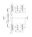
- the control unit 8 mainly includes an outdoor capacity control unit 81 and an indoor capacity control unit 82.
- the outdoor capacity control means 81 is a means for controlling the air conditioning capacity of the outdoor unit 2 so that the refrigerant evaporation temperature Te or the condensation temperature Tc in the refrigerant circuit 10 becomes the target evaporation temperature Tes or the target condensation temperature Tcs.
- the indoor capacity control means 82 is configured so that the indoor units 4 and 5 and the devices 41 and 43a and the valves 41, 43a, the indoor temperatures Tra and Trb of the conditioned space targeted by the indoor units 4 and 5 become the target indoor temperatures Tras and Trbs, respectively. It is a means to control 51 and 53a.
- FIG. 2 is a control block diagram of the air conditioner 1.
- the air conditioner 1 has the refrigerant circuit 10 configured by connecting a plurality of (here, two) indoor units 4 and 5 to the outdoor unit 2.
- the air conditioner 1 has indoor heat exchangers 42 and 52 and indoor fans 43 and 53 in the indoor units 4 and 5, and can manually instruct the air volume setting of the indoor fans 43 and 53. .
- the following air conditioning operation and control are performed by the control unit 8.
- the low-pressure gas refrigerant in the refrigerant circuit 10 is sucked into the compressor 21 and compressed to become a high-pressure gas refrigerant.
- the high-pressure gas refrigerant is sent to the outdoor heat exchanger 23 via the switching mechanism 22.
- the high-pressure gas refrigerant sent to the outdoor heat exchanger 23 is condensed by being cooled by exchanging heat with outdoor air supplied by the outdoor fan 25 in the outdoor heat exchanger 23 functioning as a refrigerant radiator.
- a high-pressure liquid refrigerant is obtained.
- the high-pressure liquid refrigerant is sent from the outdoor unit 2 to the indoor units 4 and 5 via the outdoor expansion valve 24 and the liquid refrigerant communication pipe 6.
- the high-pressure liquid refrigerant sent to the indoor units 4 and 5 is decompressed by the indoor expansion valves 41 and 51 to become a low-pressure gas-liquid two-phase refrigerant.
- This low-pressure gas-liquid two-phase refrigerant is sent to the indoor heat exchangers 42 and 52.
- the low-pressure gas-liquid two-phase refrigerant sent to the indoor heat exchangers 42 and 52 is supplied to the indoor air supplied by the indoor fans 43 and 53 in the indoor heat exchangers 42 and 52 that function as a refrigerant evaporator. By evaporating by heating through heat exchange, it becomes a low-pressure gas refrigerant.
- the low-pressure gas refrigerant is sent from the indoor units 4 and 5 to the outdoor unit 2 via the gas refrigerant communication pipe 7.
- the low-pressure gas refrigerant sent to the outdoor unit 2 is again sucked into the compressor 21 via the switching mechanism 22.
- the low-pressure gas refrigerant in the refrigerant circuit 10 is sucked into the compressor 21 and compressed to become a high-pressure gas refrigerant.
- the high-pressure gas refrigerant is sent from the outdoor unit 2 to the indoor units 4 and 5 via the switching mechanism 22 and the gas refrigerant communication pipe 7.
- the high-pressure gas refrigerant sent to the indoor units 4 and 5 is sent to the indoor heat exchangers 42 and 52.
- the high-pressure gas refrigerant sent to the indoor heat exchangers 42 and 52 exchanges heat with the indoor air supplied by the indoor fans 43 and 53 in the indoor heat exchangers 42 and 52 that function as a refrigerant radiator. It is condensed by being cooled to become a high-pressure liquid refrigerant.
- This high-pressure liquid refrigerant is depressurized by the indoor expansion valves 41 and 51.
- the refrigerant decompressed by the indoor expansion valves 41 and 51 is sent from the indoor units 4 and 5 to the outdoor unit 2 via the liquid refrigerant communication pipe 6.
- the refrigerant sent to the outdoor unit 2 is sent to the outdoor expansion valve 24, where it is depressurized by the outdoor expansion valve 24 to become a low-pressure gas-liquid two-phase refrigerant.
- the low-pressure gas-liquid two-phase refrigerant is sent to the outdoor heat exchanger 23.
- the low-pressure gas-liquid two-phase refrigerant sent to the outdoor heat exchanger 23 is heated by exchanging heat with outdoor air supplied by the outdoor fan 25 in the outdoor heat exchanger 23 functioning as an evaporator of the refrigerant. As a result, it evaporates and becomes a low-pressure gas refrigerant.
- the low-pressure gas refrigerant is again sucked into the compressor 21 via the switching mechanism 22.
- the air conditioning capability of the outdoor unit 2 is set so that the refrigerant evaporation temperature Te or the condensation temperature Tc in the refrigerant circuit 10 becomes the target evaporation temperature Tes or the target condensation temperature Tcs. Be controlled. Further, the indoor temperatures Tra and Trb in the indoor units 4 and 5 are set so that the indoor temperatures Tra and Trb of the air-conditioned space targeted by the indoor units 4 and 5 become the target indoor temperatures Tras and Trbs, respectively. 5 indoor expansion valves 41 and 51 are controlled. The target indoor temperatures Tras and Trbs in the indoor units 4 and 5 are set by the remote controllers 48 and 58, respectively. In addition, the air conditioning capability control of the outdoor unit 2 is performed by the outdoor capability control means 81 of the control unit 8, and the air conditioning capability control of each indoor unit 4, 5 is performed by the indoor capability control means 82 of the control unit 8.
- the indoor capacity control means 82 of the control unit 8 sets the superheat degrees SHra and SHrb of the refrigerant at the outlets of the indoor heat exchangers 42 and 52 to the target superheat degrees SHras and SHrbs.
- the degree of opening of each of the indoor expansion valves 41 and 51 is controlled (hereinafter, this control is referred to as “superheat degree control by the indoor expansion valve”).
- the superheat degrees SHra and SHrb are the suction pressure Ps detected by the suction pressure sensor 31 and the temperature Trga of the refrigerant on the gas side of the indoor heat exchangers 42 and 52 detected by the gas side temperature sensors 45 and 55. , Trgb.
- the suction pressure Ps is converted into the refrigerant saturation temperature to obtain the evaporation temperature Te, which is a state quantity equivalent to the evaporation pressure Pe in the refrigerant circuit 10.
- the evaporating pressure Pe is a low-pressure refrigerant that flows from the outlet of the indoor expansion valves 41 and 51 to the suction side of the compressor 21 via the indoor heat exchangers 42 and 52 during the cooling operation. Is a representative pressure.
- superheat degree SHra and SHrb are obtained by subtracting the evaporation temperature Te from the temperature Trga and Trgb of the gas side refrigerant
- the outdoor capacity control means 81 of the control unit 8 controls the compressor 21 so that the evaporation temperature Te corresponding to the evaporation pressure Pe in the refrigerant circuit 10 approaches the target evaporation temperature Tes.
- the operating capacity is controlled (hereinafter, this control is referred to as “evaporation temperature control by the compressor”).
- the control of the operating capacity of the compressor 21 is performed by changing the frequency of the compressor motor 21a.
- the state quantity to be controlled is the evaporation temperature Te, but it may be the evaporation pressure Pe.
- a target evaporation pressure Pes corresponding to the target evaporation temperature Tes may be used. That is, the evaporating pressure Pe and the evaporating temperature Te, and the target evaporating pressure Pes and the target evaporating temperature Tes mean substantially the same state quantity although the wording itself is different.
- the room temperature Tra, Trb in each of the indoor units 4, 5 is set to the target room temperature Tras, Trbs by such basic control of the cooling operation.
- the indoor capacity control means 82 of the control unit 8 sets the supercooling degrees SCra and SCrb of the refrigerant at the outlets of the indoor heat exchangers 42 and 52 to the target supercooling degrees SCras and SCrbs.
- the opening degree of each indoor expansion valve 41, 51 is controlled (hereinafter, this control is referred to as “supercooling degree control by the indoor expansion valve”).
- the degree of supercooling SCra and SCrb are the discharge pressure Pd detected by the discharge pressure sensor 32 and the temperature of the refrigerant on the liquid side of the indoor heat exchangers 42 and 52 detected by the liquid side temperature sensors 44 and 54. Calculated from Trla and Trlb.
- the discharge pressure Pd is converted into the refrigerant saturation temperature to obtain the condensation temperature Tc, which is a state quantity equivalent to the condensation pressure Pc in the refrigerant circuit 10.
- the condensation pressure Pc represents a high-pressure refrigerant flowing from the discharge side of the compressor 21 through the indoor heat exchangers 42 and 52 to the indoor expansion valves 41 and 51 during the heating operation. Means the pressure to do.
- the subcooling degrees SCra and SCrb are obtained by subtracting the liquid-side refrigerant temperatures Trla and Trlb of the indoor heat exchangers 42 and 52 from the condensation temperature Tc.
- the outdoor capacity control means 81 of the control unit 8 controls the compressor 21 so that the condensation temperature Tc corresponding to the condensation pressure Pc in the refrigerant circuit 10 approaches the target condensation temperature Tcs.
- the operating capacity is controlled (hereinafter, this control is referred to as “condensation temperature control by the compressor”).
- the control of the operating capacity of the compressor 21 is performed by changing the frequency of the compressor motor 21a.
- the state quantity to be controlled is the condensation temperature Tc, but it may be the condensation pressure Pc.
- a target condensation pressure Pcs corresponding to the target condensation temperature Tcs may be used. That is, the condensing pressure Pc and the condensing temperature Tc, and the target condensing pressure Pcs and the target condensing temperature Tcs mean substantially the same state quantity, although the words themselves are different.
- the heating operation as the basic control, supercooling degree control by the indoor expansion valves 41 and 51 and condensing temperature control by the compressor 21 are performed.
- the room temperatures Tra and Trb in the indoor units 4 and 5 are set to the target room temperatures Tras and Trbs by such basic control of the heating operation.
- the target evaporation temperature Tes when the outside air temperature Ta is low and the air conditioning capacity of the indoor units 4 and 5 tends to be small during the cooling operation.
- the target condensation temperature Tcs is low, so that excessive air conditioning capacity of the outdoor unit 2 is suppressed. That is, the operating capacity of the compressor 21 is reduced. If it does so, the power consumption of the compressor 21 can be reduced and, thereby, the improvement of APF can be aimed at.
- the target evaporation temperature Tes and the target condensation temperature Tcs used for the evaporation temperature control and the condensation temperature control by the compressor 21 are changed according to the outside air temperature Ta. If the air volume setting of the indoor fans 43 and 53 in the indoor units 4 and 5 is manually instructed by the remote controllers 48 and 58, if the air volume is unnecessarily large (for example, the air volume L is sufficient). However, even if the air volume H is set), the manually-instructed air volume setting is maintained, and the power consumption of the indoor fans 43 and 53 is wasted.
- the power consumption of the compressor 21 is reduced.
- the APF can be improved, if the airflow of the indoor fans 43 and 53 is unnecessarily large, the indoor fans 43 and 53 may waste power and the APF may not be improved sufficiently. There is.
- Indoor air volume restriction control for forcibly restricting the air volume settings of the indoor fans 43 and 53 to the low air volume side according to the outside air temperature Ta is performed.
- the indoor air volume restriction control the air volume upper limits Gcx and Ghx of the indoor fans 43 and 53 that can be changed according to the outside air temperature Ta are provided, and the air volume upper limits Gcx and Ghx of the indoor fans 43 and 53 are reduced to reduce the indoor air volume. Limit control is performed.
- the air volume upper limit Gcx of the indoor fans 43 and 53 is reduced according to the decrease in the outside air temperature Ta, and during the heating operation, the air volume of the indoor fans 43 and 53 is increased according to the increase in the outside air temperature Ta.
- the upper limit Ghx is reduced.
- FIG. 3 is a flowchart showing the indoor air volume restriction control
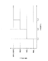
- FIG. 4 is a diagram showing the relationship between the outside air temperature Ta and the air volume upper limit Gcx of the indoor fans 43 and 53 during the cooling operation
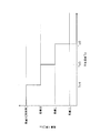
- FIG. It is a figure which shows the relationship between the outdoor temperature Ta at the time of heating operation, and the air volume upper limit Ghx of the indoor fans 43 and 53.
- FIG. The indoor air volume restriction control of the indoor fans 43 and 53 is performed by the indoor capacity control means 82 of the control unit 8.
- step ST0 it is determined whether the current air conditioning operation is a cooling operation or a heating operation.
- step ST0 if it is determined that the current air conditioning operation is the cooling operation, the process proceeds to step ST1, and if it is determined that the current air conditioning operation is the heating operation, step ST11. Move on to processing.
- steps ST1 and ST11 it is determined whether or not it is necessary to forcibly limit the air volume setting of the indoor fans 43 and 53 to the low air volume side according to the outside air temperature Ta.
- the outside air temperature Ta during the cooling operation is equal to or lower than the third outside air temperature Ta3.
- the third outside air temperature Ta3 is a threshold value as to whether or not the air volume upper limit Gcx of the indoor fans 43 and 53 during the cooling operation is limited from the air volume H (that is, no air volume limitation) to the air volume M (see FIG. 4).
- the outside air temperature Ta is equal to or higher than the fourth outside air temperature Ta4.
- the fourth outside air temperature Ta4 is a threshold value as to whether or not the air volume upper limit Ghx of the indoor fans 43 and 53 during the heating operation is limited from the air volume H (that is, no air volume restriction) to the air volume M (see FIG. 5). . If it is determined in steps ST1 and ST11 that the air volume setting of the indoor fans 43 and 53 needs to be forcibly limited to the low air volume side according to the outside air temperature Ta, the processing in steps ST2 and ST12 is performed. Transition. On the other hand, if it is determined in steps ST1 and ST11 that it is not necessary to forcibly limit the air volume setting of the indoor fans 43 and 53 to the low air volume side according to the outside air temperature Ta, the air volume of the indoor fans 43 and 53 is determined.
- the setting is not limited (substantially, the air volume upper limits Gcx and Ghx become the air volume H). For this reason, the cooling operation or the heating operation is continued while the air volume settings of the indoor fans 43 and 53 that are manually instructed from the remote controllers 48 and 58 are maintained.
- the air volume upper limits Gcx and Ghx of the indoor fans 43 and 53 that can be changed according to the outside air temperature Ta are determined. Specifically, during the cooling operation, as shown in FIG. 4, when the outside air temperature Ta is between the second outside air temperature Ta2 and the third outside air temperature Ta3, the air amount upper limit Gcx is set to the air amount M, and the outside air When the temperature Ta is a temperature between the first outside air temperature Ta1 and the second outside air temperature Ta2, the air volume upper limit Gcx is set to the air volume L, and when the outside air temperature Ta is equal to or lower than the first outside air temperature Ta1, The air volume upper limit Gcx is set to the air volume LL.
- the air volume upper limit Gcx of the indoor fans 43 and 53 is decreased according to the decrease in the outside air temperature Ta.
- the air volume upper limit Ghx is set to the air volume M
- the outside air temperature Ta is When the temperature is between the fifth outside air temperature Ta5 and the sixth outside air temperature Ta6, the air volume upper limit Ghx is set to the air volume L, and when the outside air temperature Ta is a temperature equal to or higher than the sixth outside air temperature Ta6, the air volume upper limit Ghx.
- the air volume upper limit Ghx of the indoor fans 43 and 53 is decreased according to the increase in the outside air temperature Ta.
- step ST2 and step ST12 after determining the air volume upper limits Gcx and Ghx of the indoor fans 43 and 53 that can be changed according to the outside air temperature Ta, the process proceeds to steps ST3 and ST13, and the indoor fan 43 , 53 is performed to restrict the air volume setting to the low air volume side according to the outside air temperature Ta. That is, the air volume upper limits Gcx and Ghx of the indoor fans 43 and 53 are set to the air volumes determined in step ST2 and step ST12. For example, when the outside air temperature Ta is a temperature between the first outside air temperature Ta1 and the second outside air temperature Ta2, and the air volume setting of the indoor fans 43 and 53 is manually instructed to the air volume H from the remote controllers 48 and 58. Assume the case of cooling operation.
- the air volume setting of the indoor fans 43 and 53 is limited from the manually instructed air volume H to the air volume L that is the air volume upper limit Gcx.
- the outside air temperature Ta is a temperature between the fifth outside air temperature Ta5 and the sixth outside air temperature Ta6, and the air volume setting of the indoor fans 43 and 53 is manually instructed to the air volume H from the remote controllers 48 and 58.
- the air volume upper limit Ghx becomes the air volume L in step ST12
- the air volume setting of the indoor fans 43 and 53 is limited from the manually instructed air volume H to the air volume L that is the air volume upper limit Ghx.
- the indoor air volume restriction control is performed in a state where the air volume setting of the indoor fans 43 and 53 is manually instructed, so that the air volume of the indoor fans 43 and 53 is unnecessarily large as viewed from the outside air temperature Ta. In the state, the air volume of the indoor fans 43 and 53 can be forcibly reduced.
- the indoor air volume restriction control is performed by providing the air volume upper limit Gcx, Ghx of the indoor fans 43, 53. Therefore, the air volume setting of the indoor fans 43, 53 instructed manually is performed. Is higher than the air volume upper limits Gcx and Ghx, the air volume setting of the indoor fans 43 and 53 can be forcibly reduced to the air volume upper limits Gcx and Ghx. On the other hand, if the air volume setting of the indoor fans 43 and 53 that are manually instructed is equal to or less than the air volume upper limits Gcx and Ghx, the air volume settings of the indoor fans 43 and 53 are set manually. The air volume setting can be maintained.
- the indoor air volume restriction control can be performed while maintaining the air volume settings of the indoor fans 43 and 53 that are manually instructed as much as possible.
- the indoor air volume restriction control as described above has the advantages as described above, it generates a case where the air volume setting of the indoor fans 43 and 53 that the user manually instructs is ignored. There may be users who do not want to apply the control.
- the indoor air volume restriction setting means 83 is provided in the control unit 8. ing.
- the indoor air volume restriction setting unit 83 is a memory provided in the outdoor control unit 37 of the control unit 8, and the indoor air volume is set by communication from an external device for performing various control settings of the air conditioner 1. It is possible to set whether or not to apply the limit control, the relationship value between the outside air temperature Ta and the air volume upper limits Gcx and Ghx, and the like.
- the indoor air volume restriction setting unit 83 is not limited to the above-described one. For example, whether the indoor air volume restriction control is applied, such as a dip switch provided in the outdoor control unit 37, or the outside air. Any value can be used as long as it can set the relationship value of the temperature Ta-air volume upper limit Gcx, Ghx.
- FIG. 6 is a flowchart showing a main part of the indoor air volume restriction control according to the present modification.
- the indoor air volume restriction control of the indoor fans 43 and 53 is performed by the indoor capacity control means 82 of the control unit 8 as in the above embodiment.
- processing in steps ST4 and ST14 is added to determine whether or not the room temperatures Tra and Trb are away from the target indoor temperatures Tras and Trbs. judge.
- the temperature difference obtained by subtracting the target room temperature Tras, Trbs from the room temperature Tra, Trb during the cooling operation, or the room temperature difference ⁇ Tr obtained by subtracting the room temperature Tra, Trb from the target room temperature Tras, Trbs during the heating operation. Is greater than or equal to the air flow restriction relaxation temperature difference ⁇ Trs.
- Steps ST4 and ST14 when it is determined that the indoor temperature difference ⁇ Tr is equal to or larger than the air flow restriction relaxation temperature difference ⁇ Trs, Steps ST5 and ST15 are added, and the process proceeds to Steps ST5 and ST15. .
- the air volume upper limits Gcx and Ghx of the indoor fans 43 and 53 set in steps ST3 and ST13 are set. maintain.
- steps ST5 and ST15 the air volume upper limits Gcx and Ghx of the indoor fans 43 and 53 are relaxed.
- the air volume is increased by one or more steps from the air volume upper limits Gcx and Ghx of the indoor fans 43 and 53 set in steps ST3 and ST13.
- the outside air temperature Ta is a temperature between the first outside air temperature Ta1 and the second outside air temperature Ta2
- the air volume setting of the indoor fans 43 and 53 is manually instructed to the air volume H from the remote controllers 48 and 58. Assume the case of cooling operation.
- the air volume upper limit Gcx becomes the air volume L in step ST2
- the air volume setting of the indoor fans 43 and 53 is limited from the manually instructed air volume H to the air volume L that is the air volume upper limit Gcx in step ST3.
- the air volume upper limit Gcx is increased from the air volume L to the air volume M in step ST5, thereby reducing the low air volume side. The restrictions on are relaxed.
- the outside air temperature Ta is a temperature between the fifth outside air temperature Ta5 and the sixth outside air temperature Ta6, and the air volume setting of the indoor fans 43 and 53 is manually instructed to the air volume H from the remote controllers 48 and 58. Assume a case of heating operation. In this case, since the air volume upper limit Ghx becomes the air volume L in step ST12, the air volume setting of the indoor fans 43 and 53 is limited from the manually instructed air volume H to the air volume L that is the air volume upper limit Ghx.
- step ST14 if it is determined in step ST14 that the indoor temperature difference ⁇ Tr is equal to or larger than the air volume restriction relaxation temperature difference ⁇ Trs, the air volume upper limit Ghx is increased from the air volume L to the air volume M in step ST15, thereby reducing the low air volume side. The restrictions on are relaxed.
- the indoor air volume restriction control can be appropriately performed in consideration of not only the outside air temperature Ta but also changes in the indoor temperatures Tra and Trb.
- the indoor air volume restriction control is performed, and the indoor temperature Tra When the Trb is away from the target indoor temperatures Tras and Trbs, the indoor air volume restriction control is not performed.
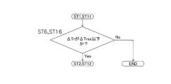
- FIG. 7 is a flowchart showing a main part of the indoor air volume restriction control according to the present modification.
- the indoor air volume restriction control of the indoor fans 43 and 53 is performed by the indoor capacity control means 82 of the control unit 8 in the same manner as in the above embodiment and the modified example ⁇ A>.
- steps ST6 and ST16 are performed.
- a process is added to determine whether the room temperatures Tra and Trb are close to the target room temperatures Tras and Trbs.
- steps ST6 and ST16 If it is determined in steps ST6 and ST16 that the indoor temperature difference ⁇ Tr is equal to or smaller than the air volume restriction allowable temperature difference ⁇ Trss, the process proceeds to steps ST2 and ST12. On the other hand, if it is determined in steps ST6 and ST16 that the indoor temperature difference ⁇ Tr is larger than the air volume restriction allowable temperature difference ⁇ Trss, the air flow setting of the indoor fans 43 and 53 is not limited, and the remote controllers 48 and 58 are used. The cooling operation and the heating operation are continued while maintaining the air volume settings of the indoor fans 43 and 53 that are manually instructed.
- the indoor air volume restriction control can be appropriately performed in consideration of not only the outside air temperature Ta but also the indoor air conditioning load.
- the determination of the indoor temperature difference ⁇ Tr in step ST6 and step ST16 may be made by each indoor unit 4, 5 or the representative value of the indoor temperature difference ⁇ Tr of the indoor units 4, 5 is used. You may determine collectively. For example, it may be determined whether the average value of the indoor temperature differences ⁇ Tr of the indoor units 4 and 5 is equal to or less than the air volume restriction allowable temperature difference ⁇ Trss. Further, it may be determined whether or not the maximum value of the indoor temperature difference ⁇ Tr of the indoor units 4 and 5 is equal to or less than the air volume restriction allowable temperature difference ⁇ Trss.
- the minimum value of the indoor temperature difference ⁇ Tr of the indoor units 4 and 5 is equal to or less than the air volume restriction allowable temperature difference ⁇ Trss. Further, it may be determined whether or not the weighted average value of the indoor temperature difference ⁇ Tr of the indoor units 4 and 5 is equal to or less than the air volume restriction allowable temperature difference ⁇ Trss.
- the weighted average value a value in consideration of the operating capacity of each indoor unit 4, 5, for example, ⁇ (operating capacity of each indoor unit ⁇ indoor temperature difference ⁇ Tr) ⁇ number of indoor units can be used.
- the indoor air conditioning load is determined by the openings MVa and MVb of the indoor expansion valves 41 and 51 as the indoor flow control valves that increase as the flow rate of the refrigerant flowing through the indoor heat exchangers 42 and 52 increases. Whether or not is large is determined.
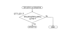
- FIG. 8 is a flowchart showing a main part of the indoor air volume restriction control according to the present modification.
- the indoor air volume restriction control of the indoor fans 43 and 53 is performed by the indoor capacity control means 82 of the control unit 8 in the same manner as in the above embodiment and the modified examples ⁇ A> and ⁇ B>.
- steps ST1 and ST11 when it is determined in steps ST1 and ST11 that it is necessary to forcibly limit the air volume setting of the indoor fans 43 and 53 to the low air volume side according to the outside air temperature Ta, or In addition to the determination in ST11, in steps ST6 and ST16, when it is determined that the room temperature Tra, Trb is close to the target room temperature Tras, Trbs, the process in steps ST7 and ST17 is added to add an indoor flow rate control valve. It is determined whether or not the opening MVa and MVb of the indoor expansion valves 41 and 51 are equal to or less than the air volume restriction permission opening MVas and MVbs.
- Steps ST7 and ST17 when it is determined that the opening MVa and MVb of the indoor expansion valves 41 and 51 as the indoor flow control valves are equal to or less than the air volume restriction permission opening MVas and MVbs, Steps ST2 and ST12 are performed. Move on to processing. On the other hand, if it is determined in step ST7 and step ST17 that the openings MVa and MVb of the indoor expansion valves 41 and 51 as the indoor flow control valves are larger than the air volume restriction permission openings MVas and MVbs, the indoor fan 43 The air flow setting of the indoor fans 43 and 53 manually instructed from the remote controllers 48 and 58 is maintained, and the cooling operation and the heating operation are continued without restricting the air flow setting of 53 and 53.
- the indoor air volume restriction control can be appropriately performed in consideration of not only the outside air temperature Ta but also the indoor air conditioning load.
- limiting control is performed by providing the air volume upper limit of the indoor fans 43 and 53 which can be changed according to the outside temperature Ta, it is not limited to this. Absent.
- the air volume setting of the indoor fans 43 and 53 instructed manually may be decreased to one or more lower air volume sides when it is determined that the indoor air volume restriction control is necessary.
- each indoor unit 4, 5 has applied this invention to the air conditioning apparatus 1 which has the indoor expansion valves 41 and 51 as an indoor flow control valve, it is limited to this. Instead, the present invention may be applied to an air conditioner that has indoor expansion valves 41 and 51 as indoor flow control valves in the outdoor unit 2.
- the present invention is widely applicable to an air conditioner capable of manually instructing the air volume setting of an indoor fan.
Abstract
L'invention porte sur un dispositif de climatisation (1), lequel dispositif comporte une unité extérieure (2) et des unités intérieures (4, 5) ayant respectivement un échangeur de chaleur intérieur (42, 52) et un ventilateur intérieur (43, 53), et dans lequel l'établissement d'écoulement d'air du ventilateur intérieur (43, 53) peut être établi manuellement. De plus, quand l'établissement d'écoulement d'air des ventilateurs intérieurs (43, 53) a été spécifié manuellement, une commande de limitation d'écoulement d'air intérieur est effectuée, par laquelle l'établissement d'écoulement d'air des ventilateurs intérieurs (43, 53) est limité de façon à être réduit en fonction de la température d'air extérieur.
Priority Applications (3)
| Application Number | Priority Date | Filing Date | Title |
|---|---|---|---|
| EP15743329.3A EP3101362B1 (fr) | 2014-01-28 | 2015-01-20 | Dispositif de climatisation |
| CN201580006095.0A CN105940275B (zh) | 2014-01-28 | 2015-01-20 | 空调装置 |
| US15/113,771 US10161651B2 (en) | 2014-01-28 | 2015-01-20 | Air conditioning apparatus |
Applications Claiming Priority (2)
| Application Number | Priority Date | Filing Date | Title |
|---|---|---|---|
| JP2014013429A JP5846226B2 (ja) | 2014-01-28 | 2014-01-28 | 空気調和装置 |
| JP2014-013429 | 2014-01-28 |
Publications (1)
| Publication Number | Publication Date |
|---|---|
| WO2015115251A1 true WO2015115251A1 (fr) | 2015-08-06 |
Family
ID=53756828
Family Applications (1)
| Application Number | Title | Priority Date | Filing Date |
|---|---|---|---|
| PCT/JP2015/051405 WO2015115251A1 (fr) | 2014-01-28 | 2015-01-20 | Dispositif de climatisation |
Country Status (5)
| Country | Link |
|---|---|
| US (1) | US10161651B2 (fr) |
| EP (1) | EP3101362B1 (fr) |
| JP (1) | JP5846226B2 (fr) |
| CN (1) | CN105940275B (fr) |
| WO (1) | WO2015115251A1 (fr) |
Families Citing this family (7)
| Publication number | Priority date | Publication date | Assignee | Title |
|---|---|---|---|---|
| JP5846226B2 (ja) | 2014-01-28 | 2016-01-20 | ダイキン工業株式会社 | 空気調和装置 |
| CN104633869B (zh) * | 2015-03-16 | 2017-06-06 | 珠海格力电器股份有限公司 | 空调室外机的控制方法及系统 |
| KR102346627B1 (ko) * | 2015-09-30 | 2022-01-05 | 엘지전자 주식회사 | 공기조화기 및 그 제어방법 |
| WO2017077647A1 (fr) * | 2015-11-06 | 2017-05-11 | 三菱電機株式会社 | Unité extérieure et climatiseur utilisant ladite unité |
| JP6493460B2 (ja) * | 2017-07-20 | 2019-04-03 | ダイキン工業株式会社 | 冷凍装置 |
| CN108006890B (zh) * | 2017-11-03 | 2020-10-09 | 特灵空调系统(中国)有限公司 | 空调散热控制方法、空调散热控制装置和空调 |
| CN113864984B (zh) * | 2021-10-19 | 2022-11-18 | 宁波奥克斯电气股份有限公司 | 空调器apf自动调试方法、装置、计算机设备及存储介质 |
Citations (5)
| Publication number | Priority date | Publication date | Assignee | Title |
|---|---|---|---|---|
| JPH05164391A (ja) * | 1991-12-13 | 1993-06-29 | Toshiba Corp | 空気調和機 |
| JPH05280796A (ja) * | 1992-03-30 | 1993-10-26 | Sanyo Electric Co Ltd | 空気調和機 |
| JP2002147823A (ja) | 2000-11-13 | 2002-05-22 | Daikin Ind Ltd | 空気調和装置 |
| JP2003106612A (ja) * | 2001-09-27 | 2003-04-09 | Daikin Ind Ltd | 空気調和装置 |
| JP2011252655A (ja) * | 2010-06-02 | 2011-12-15 | Hitachi Appliances Inc | 空気調和機の制御方法、及び空気調和機 |
Family Cites Families (12)
| Publication number | Priority date | Publication date | Assignee | Title |
|---|---|---|---|---|
| US4364237A (en) * | 1981-02-02 | 1982-12-21 | Borg-Warner Corporation | Microcomputer control for inverter-driven heat pump |
| MY130939A (en) * | 1993-06-01 | 2007-07-31 | Hitachi Ltd | Air-conditioning equipment |
| US5440895A (en) | 1994-01-24 | 1995-08-15 | Copeland Corporation | Heat pump motor optimization and sensor fault detection |
| US5634346A (en) * | 1995-10-03 | 1997-06-03 | U.S. Natural Resources, Inc. | Apparatus and method for controlling a room air conditioner |
| US20030225542A1 (en) * | 2002-05-28 | 2003-12-04 | Chang-Ming Liu | Electronic fan capable of automatic fan speed adjustment according to ambient temperature conditions |
| US6907745B2 (en) * | 2003-06-26 | 2005-06-21 | Carrier Corporation | Heat pump with improved performance in heating mode |
| KR100539765B1 (ko) * | 2004-05-21 | 2006-01-12 | 엘지전자 주식회사 | 유니터리 공기조화기 및 그의 제어방법 |
| US20080041081A1 (en) * | 2006-08-15 | 2008-02-21 | Bristol Compressors, Inc. | System and method for compressor capacity modulation in a heat pump |
| US20120053738A1 (en) * | 2009-11-24 | 2012-03-01 | Friedrich Air Conditioning Co., A Division Of U.S. Natural Resources, Inc. | Remote control system for a room air conditioner and/or heat pump |
| JP5507231B2 (ja) * | 2009-12-16 | 2014-05-28 | 三洋電機株式会社 | 空気調和機 |
| JP4947221B2 (ja) * | 2010-05-11 | 2012-06-06 | ダイキン工業株式会社 | 空気調和装置の運転制御装置及びそれを備えた空気調和装置 |
| JP5846226B2 (ja) | 2014-01-28 | 2016-01-20 | ダイキン工業株式会社 | 空気調和装置 |
-
2014
- 2014-01-28 JP JP2014013429A patent/JP5846226B2/ja active Active
-
2015
- 2015-01-20 CN CN201580006095.0A patent/CN105940275B/zh active Active
- 2015-01-20 EP EP15743329.3A patent/EP3101362B1/fr active Active
- 2015-01-20 US US15/113,771 patent/US10161651B2/en active Active
- 2015-01-20 WO PCT/JP2015/051405 patent/WO2015115251A1/fr active Application Filing
Patent Citations (5)
| Publication number | Priority date | Publication date | Assignee | Title |
|---|---|---|---|---|
| JPH05164391A (ja) * | 1991-12-13 | 1993-06-29 | Toshiba Corp | 空気調和機 |
| JPH05280796A (ja) * | 1992-03-30 | 1993-10-26 | Sanyo Electric Co Ltd | 空気調和機 |
| JP2002147823A (ja) | 2000-11-13 | 2002-05-22 | Daikin Ind Ltd | 空気調和装置 |
| JP2003106612A (ja) * | 2001-09-27 | 2003-04-09 | Daikin Ind Ltd | 空気調和装置 |
| JP2011252655A (ja) * | 2010-06-02 | 2011-12-15 | Hitachi Appliances Inc | 空気調和機の制御方法、及び空気調和機 |
Also Published As
| Publication number | Publication date |
|---|---|
| EP3101362A4 (fr) | 2017-11-15 |
| US10161651B2 (en) | 2018-12-25 |
| JP2015140957A (ja) | 2015-08-03 |
| CN105940275A (zh) | 2016-09-14 |
| CN105940275B (zh) | 2017-09-19 |
| EP3101362A1 (fr) | 2016-12-07 |
| JP5846226B2 (ja) | 2016-01-20 |
| EP3101362B1 (fr) | 2020-10-21 |
| US20160377312A1 (en) | 2016-12-29 |
Similar Documents
| Publication | Publication Date | Title |
|---|---|---|
| JP5846226B2 (ja) | 空気調和装置 | |
| US9074787B2 (en) | Operation controller for compressor and air conditioner having the same | |
| JP5802339B2 (ja) | 空気調和装置 | |
| JP5182358B2 (ja) | 冷凍装置 | |
| JP5802340B2 (ja) | 空気調和装置 | |
| JP5598353B2 (ja) | 空気調和装置 | |
| US10139144B2 (en) | Air conditioning apparatus | |
| JP6007965B2 (ja) | 空気調和装置 | |
| WO2018164253A1 (fr) | Dispositif de climatisation | |
| JP6047381B2 (ja) | 空調機 | |
| JP6353355B2 (ja) | 空気調和装置 | |
| JP6245207B2 (ja) | 空気調和装置 | |
| JP2016102635A (ja) | 空調システム |
Legal Events
| Date | Code | Title | Description |
|---|---|---|---|
| 121 | Ep: the epo has been informed by wipo that ep was designated in this application |
Ref document number: 15743329 Country of ref document: EP Kind code of ref document: A1 |
|
| REEP | Request for entry into the european phase |
Ref document number: 2015743329 Country of ref document: EP |
|
| WWE | Wipo information: entry into national phase |
Ref document number: 2015743329 Country of ref document: EP |
|
| WWE | Wipo information: entry into national phase |
Ref document number: 15113771 Country of ref document: US |
|
| NENP | Non-entry into the national phase |
Ref country code: DE |