WO2015098677A1 - コンバイン - Google Patents
コンバイン Download PDFInfo
- Publication number
- WO2015098677A1 WO2015098677A1 PCT/JP2014/083511 JP2014083511W WO2015098677A1 WO 2015098677 A1 WO2015098677 A1 WO 2015098677A1 JP 2014083511 W JP2014083511 W JP 2014083511W WO 2015098677 A1 WO2015098677 A1 WO 2015098677A1
- Authority
- WO
- WIPO (PCT)
- Prior art keywords
- exhaust gas
- gas purification
- purification device
- threshing
- grain storage
- Prior art date
- Legal status (The legal status is an assumption and is not a legal conclusion. Google has not performed a legal analysis and makes no representation as to the accuracy of the status listed.)
- Ceased
Links
Images






Classifications
-
- A—HUMAN NECESSITIES
- A01—AGRICULTURE; FORESTRY; ANIMAL HUSBANDRY; HUNTING; TRAPPING; FISHING
- A01D—HARVESTING; MOWING
- A01D41/00—Combines, i.e. harvesters or mowers combined with threshing devices
- A01D41/12—Details of combines
- A01D41/1252—Anti-dust devices
-
- B—PERFORMING OPERATIONS; TRANSPORTING
- B60—VEHICLES IN GENERAL
- B60K—ARRANGEMENT OR MOUNTING OF PROPULSION UNITS OR OF TRANSMISSIONS IN VEHICLES; ARRANGEMENT OR MOUNTING OF PLURAL DIVERSE PRIME-MOVERS IN VEHICLES; AUXILIARY DRIVES FOR VEHICLES; INSTRUMENTATION OR DASHBOARDS FOR VEHICLES; ARRANGEMENTS IN CONNECTION WITH COOLING, AIR INTAKE, GAS EXHAUST OR FUEL SUPPLY OF PROPULSION UNITS IN VEHICLES
- B60K13/00—Arrangement in connection with combustion air intake or gas exhaust of propulsion units
- B60K13/04—Arrangement in connection with combustion air intake or gas exhaust of propulsion units concerning exhaust
-
- F—MECHANICAL ENGINEERING; LIGHTING; HEATING; WEAPONS; BLASTING
- F01—MACHINES OR ENGINES IN GENERAL; ENGINE PLANTS IN GENERAL; STEAM ENGINES
- F01N—GAS-FLOW SILENCERS OR EXHAUST APPARATUS FOR MACHINES OR ENGINES IN GENERAL; GAS-FLOW SILENCERS OR EXHAUST APPARATUS FOR INTERNAL-COMBUSTION ENGINES
- F01N13/00—Exhaust or silencing apparatus characterised by constructional features
- F01N13/08—Other arrangements or adaptations of exhaust conduits
- F01N13/082—Other arrangements or adaptations of exhaust conduits of tailpipe, e.g. with means for mixing air with exhaust for exhaust cooling, dilution or evacuation
-
- F—MECHANICAL ENGINEERING; LIGHTING; HEATING; WEAPONS; BLASTING
- F01—MACHINES OR ENGINES IN GENERAL; ENGINE PLANTS IN GENERAL; STEAM ENGINES
- F01N—GAS-FLOW SILENCERS OR EXHAUST APPARATUS FOR MACHINES OR ENGINES IN GENERAL; GAS-FLOW SILENCERS OR EXHAUST APPARATUS FOR INTERNAL-COMBUSTION ENGINES
- F01N13/00—Exhaust or silencing apparatus characterised by constructional features
- F01N13/18—Construction facilitating manufacture, assembly, or disassembly
- F01N13/1805—Fixing exhaust manifolds, exhaust pipes or pipe sections to each other, to engine or to vehicle body
- F01N13/1811—Fixing exhaust manifolds, exhaust pipes or pipe sections to each other, to engine or to vehicle body with means permitting relative movement, e.g. compensation of thermal expansion or vibration
- F01N13/1822—Fixing exhaust manifolds, exhaust pipes or pipe sections to each other, to engine or to vehicle body with means permitting relative movement, e.g. compensation of thermal expansion or vibration for fixing exhaust pipes or devices to vehicle body
-
- B—PERFORMING OPERATIONS; TRANSPORTING
- B60—VEHICLES IN GENERAL
- B60Y—INDEXING SCHEME RELATING TO ASPECTS CROSS-CUTTING VEHICLE TECHNOLOGY
- B60Y2200/00—Type of vehicle
- B60Y2200/20—Off-Road Vehicles
- B60Y2200/22—Agricultural vehicles
- B60Y2200/222—Harvesters
-
- F—MECHANICAL ENGINEERING; LIGHTING; HEATING; WEAPONS; BLASTING
- F01—MACHINES OR ENGINES IN GENERAL; ENGINE PLANTS IN GENERAL; STEAM ENGINES
- F01N—GAS-FLOW SILENCERS OR EXHAUST APPARATUS FOR MACHINES OR ENGINES IN GENERAL; GAS-FLOW SILENCERS OR EXHAUST APPARATUS FOR INTERNAL-COMBUSTION ENGINES
- F01N2260/00—Exhaust treating devices having provisions not otherwise provided for
- F01N2260/20—Exhaust treating devices having provisions not otherwise provided for for heat or sound protection, e.g. using a shield or specially shaped outer surface of exhaust device
-
- F—MECHANICAL ENGINEERING; LIGHTING; HEATING; WEAPONS; BLASTING
- F01—MACHINES OR ENGINES IN GENERAL; ENGINE PLANTS IN GENERAL; STEAM ENGINES
- F01N—GAS-FLOW SILENCERS OR EXHAUST APPARATUS FOR MACHINES OR ENGINES IN GENERAL; GAS-FLOW SILENCERS OR EXHAUST APPARATUS FOR INTERNAL-COMBUSTION ENGINES
- F01N2590/00—Exhaust or silencing apparatus adapted to particular use, e.g. for military applications, airplanes, submarines
- F01N2590/08—Exhaust or silencing apparatus adapted to particular use, e.g. for military applications, airplanes, submarines for heavy duty applications, e.g. trucks, buses, tractors, locomotives
Definitions
- the present invention relates to a combine, and more particularly to a combine equipped with an exhaust gas purification device.
- Patent Document 1 there is one disclosed in Patent Document 1 as one form of combine. That is, in Patent Document 1, a reaping part is attached to the front of the machine body, a threshing part, an operation part, and a grain storage part are arranged on the machine body, and the grains of the cereals harvested by the reaping part are threshed by the threshing part And the combine which stored the grain threshed by the threshing part in the grain storage part is disclosed.
- a diesel engine is mounted in the engine room formed below the operation unit, and a diesel particulate filter (hereinafter, particulate matter in the diesel exhaust is removed) as an exhaust gas purifier on the upper surface of the diesel engine.
- a diesel particulate filter hereinafter, particulate matter in the diesel exhaust is removed
- the Diesel Particulate Filter which is a filter, is also referred to as “DPF”), and exhaust gas discharged from the diesel engine is passed through the DPF to purify the exhaust gas.
- the DPF collects particulate matter (hereinafter also referred to as “PM”) mainly composed of black smoke in the exhaust gas discharged from the diesel engine.
- the surface temperature of the DPF is also high.
- the DPF placed on the upper surface of the diesel engine is likely to accumulate dust and the like scattered from the cereals conveyed from the harvesting unit to the threshing unit, and the surface temperature of the DPF is high, There is a problem that the maintainability of the DPF is inferior.
- the present invention provides a combine that can improve the maintenance workability of the exhaust gas purification device by suppressing excessive increase in the surface temperature of the exhaust gas purification device and reducing the accumulation of dust and the like.
- the purpose is to do.
- a reaping part is attached to the front side of the machine body, and the threshing part is arranged on one side of the machine body, while the grain storage part is arranged on the other side of the machine body.
- the storage part is placed adjacent to the left and right, the diesel engine is placed at the front of the fuselage, the exhaust pipe is connected to the exhaust port of the diesel engine, and the exhaust gas purification device is installed in the middle part of the exhaust pipe
- the other side edge upper part of the threshing part close to the grain storage part side is an inclined surface part that extends downward in the shape of a downward slope to the grain storage part side, and the threshing part and the grain.
- An exhaust gas purification device formed by extending in the front-rear direction on the inclined surface portion is disposed between the storage portion and the storage portion.
- the other side upper edge part of the threshing part which adjoins the grain storage part side is made into the inclined surface part extended in the front-back direction at the grain storage part side, it is inclined surface part.
- the air permeability in the front-rear direction can be improved. Therefore, the exhaust gas purification device can be disposed on the inclined surface portion having good air permeability. As a result, it can be appropriately separated from the diesel engine disposed in the front part of the fuselage, and it is possible to suppress an excessive increase in the surface temperature of the exhaust gas purification device, and to maintain the workability of the exhaust gas purification device. Can be improved.
- the airframe can be made compact. Since the exhaust gas purification device is arranged away from the diesel engine, the engine room can be downsized.
- invention of Claim 2 is invention of Claim 1, Comprising: By making an inclined surface part of a threshing part support an exhaust gas purification apparatus via a stay, it is between an exhaust gas purification apparatus and an inclined surface part. Further, it is characterized in that a constant interval is maintained.
- invention of Claim 3 is invention of Claim 1 or 2, Comprising:
- positioned in the front part of a fuselage is connected to the front part of an exhaust gas purification apparatus via an upstream exhaust pipe.
- a downstream end of the downstream exhaust pipe is connected to the rear portion of the exhaust gas purifying device, and the downstream side exhaust pipe extends rearward above the inclined surface portion, and the distal end thereof extends rearward. It is characterized by opening toward.
- the downstream side exhaust pipe having the base end connected to the rear portion of the exhaust gas purifying device is extended rearward above the inclined surface portion, and the front end thereof is opened rearward. Therefore, the downstream exhaust pipe itself can be arranged in a compact and short width on the inclined surface portion, and the distal end portion of the downstream exhaust pipe from which the exhaust gas is exhausted is seated on the operating portion. It can be separated from the driver, and the driving environment can be improved.
- the invention according to claim 4 is the invention according to any one of claims 1 to 3, wherein the exhaust gas purifying device is higher than the upper surface of the grain storage unit positioned higher than the upper surface of the threshing unit. It is arranged at a lower position.
- the base end of the carry-out auger when the base end of the carry-out auger is pivotally connected to the grain storage part, and the grain stored in the grain storage part is carried out by the carry-out auger.
- the unloading auger can be swiveled above the grain storage unit and stored in a recumbent manner, so that the unloading auger interferes with the exhaust gas purification device disposed below the upper surface of the grain storage unit. Can be easily avoided. Further, even when the seat cover is hung on the carry-out auger stored in a horizontal shape, it can be avoided that the seat cover comes into contact with the exhaust gas purification device having a high temperature.
- the invention described in claim 5 has a cutting part attached to the front of the machine body and a threshing part is arranged on one side of the machine body, while a grain storage part is arranged on the other side of the machine body, and the threshing part and the grain are arranged.
- the storage part is placed adjacent to the left and right, the diesel engine is placed at the front of the fuselage, the exhaust pipe is connected to the exhaust port of the diesel engine, and the exhaust gas purification device is installed in the middle part of the exhaust pipe
- the other side edge upper part of the threshing part close to the grain storage part side is an inclined surface part that extends downward in the shape of a downward slope toward the grain storage part, and is directly above the inclined surface part.
- An exhaust gas purification device formed by extending in the front-rear direction at a predetermined interval is provided.
- the other side edge upper part of the threshing part close to the grain storage part side is formed as an inclined surface part extending downward in the forward and backward direction toward the grain storage part side. Since the exhaust gas purification device formed by extending in the front-rear direction with a certain interval above is disposed, the air permeability in the front-rear direction around the exhaust gas purification device can be improved. In other words, the exhaust gas purifying device can be arranged in a gradually widened space having a gradually widened left-right width and good air permeability. As a result, it can also be separated from the diesel engine arranged in the front part of the airframe appropriately, and the surface temperature of the exhaust gas purification device can be prevented from increasing. In addition, the engine room can be downsized by separating the exhaust gas purification device from the diesel engine.
- invention of Claim 6 is invention of Claim 5, Comprising: While a grain storage part pivotally supports a rear part side, it becomes possible to rotate the front part side to an outer side, and a grain storage part From the threshing part to the upper side of the exhaust gas purification device, and the fixed side locking body to project from the threshing portion to the upper side of the exhaust gas purification device.
- the movable side locking body is locked and detachably locked above the exhaust gas purification device, and dust and the like scattered from the cutting and threshing portions to the exhaust gas purification device side are fixed to the fixed side locking body. It is characterized in that a shielding body for shielding is attached.
- the both locking bodies are locked and detached.
- the exhaust gas purifying device does not hinder the operation, and the locking / disengaging operation of both the locking bodies can be performed steadily.
- the shield is attached to the fixed-side locking body projecting upward from the threshing portion toward the exhaust gas purification device, the shielding body is attached to the fixed-side locking body without separately providing a shielding body mounting member. Can be steadily supported.
- the shielding body shields dust and the like scattered from the cutting part and the threshing part to the exhaust gas purification device side, it prevents the dust and the like from staying and accumulating in the exhaust gas purification device. be able to.
- invention of Claim 7 is invention of Claim 6, Comprising: A shield is arrange
- the shielding body is disposed at a side position of the exhaust gas purifying device and above the inclined surface portion of the threshing portion, the exhaust gas purifying device side from the cutting portion, the threshing portion, or the like. It is possible to shield dust and the like scattered by the shield. At this time, since a predetermined interval is maintained between the lower edge of the shield and the inclined surface portion, the shield does not hinder the sliding of dust or the like dropped on the inclined surface portion of the threshing portion. For this reason, dust or the like does not stay or accumulate on the inclined surface portion.
- the invention described in claim 8 is the invention described in claim 7, characterized in that a middle part of the wire harness of the sensor attached to the exhaust gas purification device is supported on the side surface of the shield.
- the wire harness of the sensor attached to the exhaust gas purification device is supported on the side surface of the shield, that is, the side surface facing the exhaust gas purification device, the wire harness is neatly arranged. In addition to wiring, it is possible to prevent dust and the like scattered from adhering to the wire harness.
- the present invention has the following effects. That is, according to the present invention, it is possible to suppress an increase in the surface temperature of the exhaust gas purification device, reduce accumulation of dust and the like, and improve maintenance workability of the exhaust gas purification device. Can do.
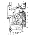
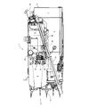
- the right view of the combine as this embodiment. The top view of the combine as this embodiment.
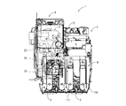
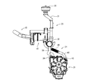
- the front view of the combine as this embodiment. The right view which shows the intake / exhaust piping part connected to the diesel engine.
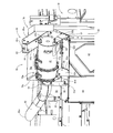
- the top view which shows the attachment state of an exhaust-gas purification apparatus.
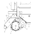
- the front view which shows the attachment state of an exhaust-gas purification apparatus.
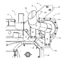
- the rear view which shows the attachment state of an exhaust-gas purification apparatus.
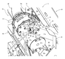
- Explanatory drawing of the right side of a shield The perspective view which shows the connection state of a fixed side coupling body and a movable side coupling body.
- the expansion perspective view which shows the connection state of a fixed side coupling body and a movable side
- the combine has a reaping part attached to the front of the machine, a threshing part is placed on one side of the machine, and a grain storage part is placed on the other side of the machine, and the threshing part and the grain storage part are Arranged adjacent to the left and right, a diesel engine is arranged at the front of the aircraft, an exhaust pipe is connected to the exhaust port of the diesel engine, and an exhaust gas purification device is provided in the middle of the exhaust pipe And the other side upper edge part of the threshing part which adjoins to the grain storage part side turns into the inclined surface part extended in the front-back direction in the shape of a downward slope to the grain storage part side, and a threshing part and a grain storage part In the meantime, an exhaust gas purification device formed by extending in the front-rear direction is disposed on the inclined surface portion.
- the inclined surface portion of the threshing portion supports the exhaust gas purification device via a stay, thereby maintaining a constant interval between the exhaust gas purification device and the inclined surface portion.
- the front part of the exhaust gas purification device is connected to the exhaust port portion of the diesel engine disposed in the front part of the fuselage via the upstream exhaust pipe, and the downstream side exhaust pipe is connected to the rear part of the exhaust gas purification device.
- the downstream exhaust pipe is extended rearward above the inclined surface portion, and the distal end portion is opened rearward.
- the exhaust gas purifying device here is disposed at a position lower than the upper surface of the grain storage unit located higher than the upper surface of the threshing unit.
- the combine has a reaping part attached to the front of the fuselage, and a threshing part is placed on one side of the fuselage, while a grain storage part is placed on the other side of the machine, and the threshing part and the grain storage part are Arranged adjacent to the left and right, a diesel engine is arranged at the front of the aircraft, an exhaust pipe is connected to the exhaust port of the diesel engine, and an exhaust gas purification device is provided in the middle of the exhaust pipe And the other side edge upper part of the threshing part which adjoins the grain storage part side turns into the inclined surface part extended in the front-back direction in the shape of a downward slope to the grain storage part side, and is fixed just above the inclined surface part.
- An exhaust gas purifying device formed by extending in the front-rear direction at an interval is disposed.
- the grain storage unit pivotally supports the rear side, and the front side can be rotated outward, and the movable side locking body is moved upward from the grain storage unit to the exhaust gas purification device.
- a fixed side locking body protrudes from the threshing portion upward of the exhaust gas purification device, and the movable side locking body is locked to the fixed side locking body above the exhaust gas purification device.
- a shielding body that is detachably locked and shields dust and the like scattered from the cutting part, the threshing part, and the like to the exhaust gas purification device side is attached to the fixed side locking body.
- the shield is disposed at a side position of the exhaust gas purifying device and above the inclined surface portion of the threshing portion, and maintains a predetermined interval between the lower end edge portion and the inclined surface portion.
- the middle part of the wire harness of the sensor attached to the exhaust gas purification device is supported on the side of the shield.
- FIGS. 1 to 4 is a combine as this embodiment.
- the overall configuration of the combine 1 will be schematically described with reference to FIGS. 1 to 4, and then the characteristic configuration of the present embodiment will be described with reference to FIGS. 7 to 15.
- the combine 1 includes a traveling machine body 3 that can freely travel in the front-rear direction.
- the traveling machine body 3 includes a pair of left and right crawler-type traveling units 2.
- a cutting unit 4 for cutting 4 stalks for cutting the cereals is attached so as to freely move up and down.
- the traveling machine body 3 is provided with a threshing unit 5 for threshing the cereals harvested by the reaping unit 4 on the upper left side in the forward direction.
- a sorting unit 6 for sorting the grains threshed by the threshing unit 5 is disposed in the lower left part of the traveling machine 3.
- a scouring processing unit 7 for processing sewage is disposed behind the threshing unit 5 and the sorting unit 6 disposed on the upper left and right parts.
- the driving unit 3 is provided with a driving unit 8 at the front part on the right side in the forward direction so that each unit is operated in the cabin.
- a grain storage unit 9 that stores the grains (fine grains) sorted by the sorting unit 6 is disposed.
- the grain storage part 9 is pivotally supported by the traveling body 3 so as to be rotatable about an axis extending in the vertical direction at the rear end.
- the grain storage part 9 makes the grain storage part 9 freely changeable in posture by rotating its front side outward on the right side. That is, the grain storage unit 9 is horizontally rotated between a use posture (harvesting work posture) oriented forward and a non-use posture (harvesting non-work posture) oriented forward right. It can be changed freely.
- a carry-out unit 10 for carrying out the grains stored in the grain storage unit 9 to the outside is disposed.
- the carry-out unit 10 is raised from the body frame 15 and communicated with the rear end of the grain storage unit 9.
- the unloading unit 10 is connected to the upper end of the vertical auger 11 so that the base end is pivotably connected to the front end.
- a lateral auger 12 formed by being extended.
- the vertical auger 11 is pivotally supported and connected to the rear end of the grain storage unit 9 so that the grain storage unit 9 can be rotated horizontally around the axis of the vertical auger 11 extending in the vertical direction. ing.
- an engine room 20 is formed in the operating unit 8 immediately below the latter half.
- the engine room 20 is formed in a protruding shape up to a position near the center of the traveling machine body 3 (up to a position near the right front portion of the threshing portion 5).
- a diesel engine 21 that drives a drive unit of each unit is mounted in the engine room 20.
- the intake port portion 34 of the diesel engine 21 is connected to the base end portion of the intake pipe portion 23 for taking in air after purifying outside air.
- the exhaust port portion 43 of the diesel engine 21 is connected to the base end portion of the exhaust pipe portion 24 as an exhaust pipe.
- the intake piping part 23 is arranged in front of the grain storage part 9.
- the intake pipe section 23 includes a pre-cleaner 30, an upstream intake pipe 31, an air cleaner 32, and a downstream intake pipe 33, which are sequentially connected in series.
- the downstream side intake pipe 33 is connected to an intake port 34 provided in the diesel engine 21.
- outside air is taken into the air cleaner 32 from the pre-cleaner 30 through the upstream intake pipe 31 and purified by the air cleaner 32, and then the diesel is discharged from the intake port 34 through the downstream intake pipe 33. Purified outside air is sucked into the engine 21.
- the exhaust pipe section 24 includes an upstream side exhaust pipe 40, an exhaust gas purification device 41, and a downstream side exhaust pipe 42, which are sequentially connected in series.
- the upstream exhaust pipe 40 is connected to an exhaust port 43 provided in the diesel engine 21.
- a vibration-absorbing bellows portion 48 is formed in the middle portion of the upstream side exhaust pipe 40.
- the upstream side exhaust pipe 40 connects the exhaust port part 43 of the diesel engine 21 and the lower surface front part of the exhaust gas purification device 41 at the shortest distance, and vibrations from any of the front, rear, left, right, and upper directions are in the middle part. Absorption is possible by the provided bellows 48.
- the upstream side exhaust pipe 40 is formed point-symmetrically and can be connected to the exhaust port portion 43 of the diesel engine 21 and the front surface of the lower surface of the exhaust gas purification device 41 by changing both ends.
- the present embodiment is characterized in the arrangement structure of the exhaust gas purifying device 41.
- an arrangement structure of the exhaust gas purification device 41 will be described with reference to FIGS.
- the upper part of the other side edge (in the present embodiment, the upper right side edge) of the threshing part 5 adjacent to the grain storage part 9 side is inclined to the grain storage part 9 side and extends in the front-rear direction in an inclined manner. It is done. Between the threshing part 5 and the grain storage part 9 above the inclined surface part 50, an arrangement space 51 for arranging the exhaust gas purification device 41 is formed.
- the installation space 51 is formed by extending in the front-rear direction, and can accommodate the exhaust gas purification device 41 formed by extending in the front-rear direction in the installation space 51.
- the exhaust gas purification device 41 is arranged at a certain distance D1 directly above the inclined surface portion 50. That is, the exhaust gas purifying device 41 is supported in a horizontal manner on the inclined surface portion 50 of the threshing portion 5 via the front stay 52 and the rear stay 53. A constant distance D1 is maintained between the exhaust gas purification device 41 and the inclined surface portion 50.
- the ceiling surface part 57 of the grain storage part 9 is arranged at a higher position than the ceiling surface part 56 of the threshing part 5.
- the exhaust gas purification device 41 is disposed at a position lower than the upper surface of the ceiling surface portion 57 of the grain storage unit 9 positioned higher than the upper surface of the ceiling surface portion 56 of the threshing unit 5.
- An exhaust gas purification device is connected to an exhaust port portion of the diesel engine 21 disposed at the front portion of the traveling machine body 3 via an upstream exhaust pipe 40 (see FIGS. 5 and 6) that forms the upstream side of the exhaust pipe portion 24.
- the inflow side connection part 54 provided in the front lower part of the surrounding wall 41a of 41 is connected.
- the base end part of the downstream exhaust pipe 42 which forms the downstream of the exhaust piping part 24 is connected to the outflow side communication part 55 provided in the rear end wall 41c of the exhaust gas purification device 41 in a non-contact state. Yes.
- the downstream side exhaust pipe 42 extends rearward along the inclined surface portion 50, and the front end portion 42a is opened rearward.
- the grain storage unit 9 pivotally supports the rear end portion of the traveling machine body 3 and can rotate the front side to the outer side (right side in this embodiment).
- a movable side locking body 60 projects from the exhaust gas purification device 41 upward.
- the threshing unit 5 is provided with a fixed-side locking body 61 projecting upward from the exhaust gas purification device 41.
- the movable side locking body 60 is locked to the fixed side locking body 61 so as to be locked and detachable above the exhaust gas purification device 41.
- a shield 70 and an auxiliary shield 74 that shield dust and the like scattered from the cutting unit 4 and the threshing unit 5 to the exhaust gas purification device 41 side are attached to the fixed side locking body 61.
- the shield 70 is attached by being extended rearward from the fixed-side locking body 61.
- the auxiliary shield 74 is attached so as to protrude forward from the fixed-side locking body 61.
- the shield 70 is disposed on the left side of the exhaust gas purification device 41 and above the inclined surface portion 50 of the threshing portion 5. A predetermined distance D ⁇ b> 2 is held between the lower edge of the shield 70 and the inclined surface part 50. As shown in FIG. 13, a midway portion of the wire harness 73 is supported on the inner surface of the shield 70 via a support 71. The wire harness 73 is energized to a temperature sensor or the like (not shown) attached to the exhaust gas purification device 41.
- the exhaust gas purification device 41 By configuring the arrangement structure of the exhaust gas purification device 41 as described above, the following actions and effects are produced. That is, since the other side edge upper part of the threshing part 5 which adjoins the grain storage part 9 side is made into the inclined surface part 50 extended in the front-back direction at the grain storage part 9 side, it is on the inclined surface part 50. The air permeability in the front-rear direction can be improved. In other words, the exhaust gas purifying device 41 can be disposed in the gradually widened space on the inclined surface portion 50 with the right and left widths gradually widening upward and good air permeability.
- the exhaust gas purification device 41 can be appropriately separated from the diesel engine 21 disposed in the front portion of the traveling machine body 3, the excessive increase in the surface temperature of the exhaust gas purification device 41 can be suppressed, and the exhaust gas purification device.
- the maintenance workability of 41 can be improved. Further, since dust or the like that has fallen on the inclined surface portion 50 can be slid between the threshing portion 5 and the grain storage portion 9, dust or the like around the exhaust gas purifying device 41 disposed on the inclined surface portion 50. Can be reduced. Further, since the exhaust gas purification device 41 is disposed on the inclined surface portion 50, the traveling machine body 3 can be made compact. Since the exhaust gas purification device 41 is disposed away from the diesel engine 21, the engine room 20 can be downsized.
- the downstream side exhaust pipe 42 having a base end connected to the rear part of the exhaust gas purifying device 41 extends rearward above the inclined surface part 50, and the front end part 42a is opened rearward. Therefore, the downstream exhaust pipe 42 can be disposed in a compact and short width above the inclined surface portion 50. And the front-end
- a base end portion of a horizontal auger 12 serving as a carry-out auger is pivotally connected to an upper end portion of a vertical auger 11 communicated with the grain storage portion 9 and stored in the grain storage portion 9.
- the side auger 12 can be swiveled above the grain storage unit 9 and stored in a recumbent state, thereby allowing the side
- the interference of the gas 12 with the exhaust gas purification device 41 disposed at a position lower than the upper surface of the ceiling surface portion 57 of the grain storage unit 9 can be easily avoided. Further, even when the seat cover is hung on the horizontal auger 12 housed in a recumbent shape, the contact of the seat cover with the exhaust gas purification device 41 having a high temperature can be avoided.
- the movable side locking body 60 is locked to the fixed side locking body 61 in a freely detachable manner above the exhaust gas purification device 41. Therefore, when the both locking bodies 60, 61 are locked / released, the exhaust gas purification device 41 does not hinder, and the locking / release operation of both the locking bodies 60, 61 can be performed firmly. .
- the shield 70 is attached to a fixed-side locking body 61 that projects from the threshing portion 5 toward the upper side of the exhaust gas purification device 41. Therefore, the shielding body 70 can be firmly supported by the fixed-side locking body 61 without separately providing a shielding body attachment member. At this time, since the shield 70 shields dust and the like scattered from the cutting unit 4 and the threshing unit 5 to the exhaust gas purification device 41, the dust and the like are accumulated and accumulated in the exhaust gas purification device 41. Can be prevented.
- the shield 70 Since the shield 70 is disposed on the left side of the exhaust gas purification device 41 and above the inclined surface portion 50 of the threshing unit 5, the shield 70 is disposed on the exhaust gas purification device 41 side from the reaping unit 4, the threshing unit 5, or the like. It is possible to shield the dust and the like scattered by the shield 70. At this time, since the predetermined distance D2 is maintained between the lower edge of the shield 70 and the inclined surface portion, the shield 70 is caused to fall off dust or the like that has fallen on the inclined surface portion 50 of the threshing portion 5. It will not be a hindrance. For this reason, dust or the like does not stay or accumulate on the inclined surface portion 50.
- the middle part of the wire harness 73 such as a temperature sensor attached to the exhaust gas purification device 41 is supported on the side surface of the shield 70, that is, on the right side surface facing the exhaust gas purification device 41. Therefore, the wire harness 73 can be arranged in an orderly manner, and scattered dust and the like can be prevented from adhering to the wire harness 73.
- the threshing unit 5 includes a main threshing case 91 that houses the handling chamber 90 and a sub-threshing case 93 that houses the second reduction chamber 92.
- the main threshing case 91 is formed in a rectangular box shape.
- the sub-threshing case 93 is formed in a rectangular box shape by expanding the right side portion of the main threshing case 91 to the left side.
- the sub threshing case 93 is comprised as the inclined surface part 50 which formed the ceiling surface part in the downward slope to the right side downward.
- the front and rear width of the sub-threshing case 93 is formed to be approximately three-fourths of the front and rear width of the main threshing case 91.
- a recess 96 is formed that opens forward and to the left.
- the vertical width and front / rear width of the recess 96 are formed wider than the vertical width and front / rear width of the exhaust gas purification device 41.
- the above-described arrangement space 51 is formed in the space formed between the upper parts of the threshing part 5 and the grain storage part 9 above the inclined surface part 50 formed on the left side thereof and on the right side thereof. It is formed in the space of the recessed portion 96 so as to continuously bulge out in the left-right direction.
- the arrangement space 51 formed in this way is a gradually widened space in which the exhaust gas purifying device 41 can be accommodated, that is, a space whose left and right widths gradually widen upward.
- a second reduction cylinder 132 (described later) extending in the front-rear direction is disposed.
- stretched to an up-down direction is arrange
- the exhaust gas purifying device 41 arranged in the arrangement space 51 is arranged at a position immediately above the second reduction cylinder 132 and at a position just before the milling cylinder 136.
- the exhaust gas purifying device 41 configured in this way is compactly disposed in a disposition space 51 formed between the front upper part of the threshing unit 5 and the grain storage unit 9 and a part of the disposition space 51. Is firmly supported by the inclined surface portion 50 of the threshing portion 5.
- the inclined surface portion 50 of the threshing portion 5 is provided with a front stay 52 protruding at the front end portion thereof, and a rear stay 53 is provided in the middle portion of the inclined surface portion 50 so as to purify the exhaust gas between the stays 52 and 53.
- the exhaust gas purification device 41 is firmly supported on the inclined surface portion 50 with a certain distance D1.
- the front stay 52 is formed of a fixed piece 52a fixed in surface contact with the upper surface of the inclined surface portion 50, and a rising piece 52b extending in a rising shape from the fixed piece 52a toward the upper right side.
- a front end wall 41b of the exhaust gas purifying device 41 is attached to the upper end of the exhaust gas purification device 41.
- the rear stay 53 includes a fixed piece 53a that is fixed in surface contact with the upper surface of the inclined surface portion 50, a rising piece 53b that extends upward from the fixed piece 53a toward the upper right side, and the fixed piece 53a and the rising piece.
- the exhaust pipe base support piece 53c protrudes from the right side 53b to the right and protrudes upward at the rear edge.
- a flange portion 41d provided at the rear end peripheral portion of the exhaust gas purifying device 41 is attached to the upper end portion of the rising piece 53b, and the exhaust pipe base support piece 53c is provided downstream via a base side support auxiliary piece 80.
- the base part of the side exhaust pipe 42 is supported from below.
- Reference numeral 81 denotes an exhaust pipe mid-portion support piece projecting on the upper rear wall of the sub-threshing case 93 in order to support a midway portion of the downstream side exhaust pipe 42 from below, and 82 denotes a mid-section side support auxiliary piece. is there.
- the fixed-side locking body 61 is formed in a side-section gate shape from a plate-shaped front surface portion 61a and a rear surface portion 61b extending in the left-right direction, and a plate-shaped ceiling surface portion 61c installed between these upper end edges.
- the sub-threshing case 93 projects in a cantilevered manner from the upper front end to the upper right side.
- the fixed-side locking body 61 protrudes directly above the front portion of the exhaust gas purification device 41, and the tip end portion is disposed directly above the front portion of the exhaust gas purification device 41, thereby The upper part of the front part of the gas purification device 41 is covered.
- the fixing pin 84 which orient
- the movable side locking body 60 is formed in a horizontally-oriented pentagonal plate shape in the left-right direction, and the rear surface of the base end portion 60a is attached to the upper surface of the front wall 97 of the grain storage unit 9 in a superposed state.
- the front end portion 60b protrudes from the storage portion 9 to the left side.
- a bifurcated engagement recess 60c is formed on the left end of the tip 60b protruding leftward.
- position harvesting work attitude
- position which orientated the grain storage part 9 ahead, the engagement recessed part 60c of the movable side latching body 60 becomes the fixed pin 84 of the fixed side latching body 61. It is configured to be engageable from the side.
- a base end portion of a plate-like engagement connecting piece 86 is pivotally supported on the front surface of the distal end portion 60b of the movable side locking body 60 via a pivot pin 85 having an axis line in the front-rear direction.
- the engagement connecting piece 86 is rotatable up and down around the portion.
- a hook portion 86a having an opening in the upward direction and the front-rear direction is formed at the distal end portion of the engagement connecting piece 86 so that the hook portion 86a can be engaged with and released from the fixing pin 84 from below.
- a tension spring 87 is interposed between the engagement connecting piece 86 and the movable side locking body 60 via spring locking pieces 87a and 87b.
- the hook portion 86a is urged to rotate by a tension spring 87 in a direction engaged with the fixed pin 84 from below around the pivot pin 85 (in this embodiment, counterclockwise when viewed from the front). Yes. That is, the movable side locking body 60 can be connected to the fixed side locking body 61 by engaging the hook portion 86a with the fixing pin 84 from below.
- a guide inclined surface 86b is formed on the upper end surface of the hook portion 86a.
- the hook portion 86a is pivoted in the direction in which the hook 86a is disengaged from the fixing pin 84 around the pivot pin 85 (in this embodiment, clockwise when viewed from the front) and fixed to the engaging recess 60c.
- the pin 84 is configured to be engageable.
- the lower end of the engagement connecting piece 86 is connected to the front end portion of the connecting piece 88, while the lower portion of the front wall 97 of the grain storage portion 9 is connected to the operation lever 89 via a pivot 89 a having an axis line in the front-rear direction.
- the top of the is attached.
- the base end portion of the connecting piece 88 is connected to the middle portion of the operating lever 89 that can be rotated about the pivot 89a.
- the hook portion 86 a is configured to be disengaged from the fixed pin 84 by being rotated clockwise around the pin 85. Further, the hook 86a is disengaged from the fixing pin 84 so that the grain storage unit 9 can be changed to a non-use posture (harvesting non-working posture) oriented forward and outward. is doing.
- the shielding body 70 includes a side shielding piece 70a formed in a horizontally long rectangular plate shape in the front-rear direction, and an upper portion formed in a belt shape extending from the upper edge of the side shielding piece 70a to the upper right side and extending in the front-rear direction.
- the shielding piece 70b and the rear shielding piece 70c formed in the shape of a vertically long rectangular plate connected to the rear edge of the upper shielding piece 70b and the side shielding piece 70a are formed.
- the inclination angle of the upper shielding piece 70b is the same as the inclination angle of the ceiling surface portion 61c of the fixed-side locking body 61, and the front end edge portion 70d of the upper shielding piece 70b is extended to the upper surface side of the ceiling surface portion 61c.
- the lower surface of the extending portion is overlapped and connected to the upper surface of the ceiling surface portion 61c.
- the front end edge part of the side shielding piece 70a is made to contact
- the rear shielding piece 70c covers the left side portion of the rear end wall 41c of the exhaust gas purification device 41 from the rear.
- the support 71 includes a rod-like longitudinally extending piece 71a having a front end connected to the rear surface part 61b, a downwardly extending piece 71b extending downward from the rear end of the longitudinally extending piece 71a, and a lower end of the downwardly extending piece 71b. And a connecting piece 71c having a lower surface attached to the inclined surface portion 50 by attaching an upper surface to the inclined surface portion 50.
- Reference numeral 72 denotes an attachment bracket for attaching the support 71 to the shield 70.
- the shielding body 70 configured in this manner is supported by the support body 71 and the fixed-side locking body 61 in a state of being spaced apart from the inclined surface portion 50 by a certain width and integrated with the fixed-side locking body 61.
- the left side of the exhaust gas purification device 41 is shielded from dust and the like.
- the traveling unit 2 is provided with a drive sprocket 101, a tension roller 102, a plurality of track rollers 103, and a crawler belt 104 wound around these on a track frame 100.
- the drive sprocket 101 receives the power of the diesel engine 21 and rotates.
- the tension roller 102 maintains the tension of the crawler belt 104.
- the plurality of track rollers 103 hold the ground side of the crawler belt 104 in a grounded state.
- the front side of the crawler belt 104 is supported by the drive sprocket 101, the rear side thereof is supported by the tension roller 102, and the grounding side is supported by the track roller 103.
- the cutting unit 4 connects the cutting frame 110 to a cutting rotation fulcrum shaft (not shown) provided on the traveling machine body 3.
- the mowing unit 4 includes a clipper-type cutting blade device 111 that cuts the stock of uncut cereals in the field, four rows of culm raising devices 112 that cause uncut cereals in the field, and a cutting blade device 111.
- the cereal conveyance device 113 that conveys the chopped cereal that has been cut by the above-described method, and the four weeds 114 that divide the uncut cereal in the field.
- the cutting blade device 111 is provided at the lower part of the cutting frame 110.
- the grain raising device 112 is disposed at the front portion of the cutting frame 110.
- the cereal haul conveying device 113 is disposed between the cereal haul raising device 112 and the front end portion (feed start end side) of the feed chain 121 provided in the threshing portion 5.
- the weed body 114 protrudes from the front lower part of the grain raising apparatus 112.
- the harvesting unit 4 is driven together with the traveling unit 2 by the diesel engine 21 so as to continuously harvest uncut grain culm on the field while moving in the field.
- the threshing unit 5 is provided with a feed chain 121 on the left side wall of the handling chamber 90, and a handling cylinder 122 for threshing threshing in the handling chamber 90 around an axis extending in the front-rear direction. It is pivotably attached. Then, the grain barrel is sandwiched by the feed chain 121 and conveyed backward in a state where the head portion is disposed on the lower peripheral surface side of the handling barrel 122 in which the tip portion rotates. The grain of the tip is threshed.
- the sorting unit 6 swings and sorts the grains that have been threshed by the handling cylinder 122 and fall downward, and supplies the sorting wind to the swinging sorter 125.
- the processing cylinder 133 for reprocessing the threshing waste taken out from the rear part of the handling cylinder 122, and the rocking sorter 125
- a dust exhaust fan 134 for discharging the dust exhaust at the rear part to the outside of the machine.
- the swing sorter 125 is configured to swing sort (specific gravity sort) the grains that have been threshed by the handling drum 122 and dropped downward.
- the grain that has fallen from the rocking sorter 125 (first sort) has its dust in the grain removed by the sorting wind from the Kara 126 and the auxiliary Kara 127, and falls to the No. 128.
- a cereal cylinder extending in the vertical direction is provided at a terminal end (right end) protruding outward from one side wall (right side wall in the embodiment) of the threshing unit 5 near the grain storage unit 9.
- a lower end portion of 136 is connected in a communication state.
- the grain taken out from the first basket 128 is carried into the grain storage unit 9 by the cereal conveyor (not shown) in the brewing cylinder 136 and stored in the grain storage unit 9.
- Oscillating sorter 125 is used to sort second grain (reduction-reprocessed product for re-sorting of grain and swarf etc.) such as grain with branch branch by swing sorting (specific gravity sorting). It is comprised so that it may fall to 130.
- the second grain taken out by the second basket 130 is returned by the second reduction cylinder 132 from the front end portion 137 of the second reduction cylinder to the upper surface side of the swing sorter 125 and re-sorted. Further, sawdust, dust, and the like in the crushed material from the handling drum 122 are discharged from the rear part of the traveling machine body 3 toward the field by the sorting wind from the Kara 126 and the auxiliary Kara 127.
- the waste disposal unit 7 has a waste chain 135 disposed on the rear end side (feed end side) of the feed chain 121.
- the waste passed through the feed chain 121 from the rear end side of the feed chain 121 (the rice cake from which the grain has been shed) is discharged to the rear of the traveling machine body 3 in the long state, or behind the threshing unit 5.
- the paper After being cut to an appropriate length by a waste cutter (not shown) provided on the side, the paper is discharged to the lower rear of the traveling machine body 3.
Landscapes
- Engineering & Computer Science (AREA)
- Chemical & Material Sciences (AREA)
- Combustion & Propulsion (AREA)
- Mechanical Engineering (AREA)
- General Engineering & Computer Science (AREA)
- Transportation (AREA)
- Life Sciences & Earth Sciences (AREA)
- Environmental Sciences (AREA)
- Combines (AREA)
Abstract
排気ガス浄化装置の表面温度の過剰な高温化を抑制するとともに、塵埃等の蓄積を低減させることで、排気ガス浄化装置のメンテナンス作業性を向上させることができるコンバインを提供すること。 穀粒貯留部側に近接する脱穀部の他側縁上部は、穀粒貯留部側に下り傾斜状で前後方向に延伸する傾斜面部となして、脱穀部と穀粒貯留部との間において、傾斜面部上に前後方向に延伸させて形成した排気ガス浄化装置を配置した。
Description
本発明は、コンバイン、詳しくは、排気ガス浄化装置を装備したコンバインに関する。
従来、コンバインの一形態として、特許文献1に開示されたものがある。すなわち、特許文献1には、機体の前方に刈取部を取り付け、機体に脱穀部と運転部と穀粒貯留部を配設して、刈取部により刈り取った穀稈の穀粒を脱穀部で脱穀し、脱穀部で脱穀された穀粒を穀粒貯留部に貯留するようにしたコンバインが開示されている。そして、運転部の下方に形成されたエンジンルーム内には、ディーゼルエンジンを搭載し、ディーゼルエンジンの上面に排気ガス浄化装置であるディーゼルパティキュレートフィルタ(以下、ディーゼル排気中の粒子状物質を除去するフィルタであるDiesel Particulate Filter を略した「DPF」ともいう。)を載置して、ディーゼルエンジンから排出された排気ガスをDPF中に通過させることで、排気ガスを浄化するようにしている。ここで、DPFは、ディーゼルエンジンから排出される排気ガス中の黒煙を主体とする粒子状物質(以下、「PM」ともいう。)等を捕集するものである。
しかしながら、上記したコンバインでは、雰囲気温度の高いエンジンルーム内に搭載したディーゼルエンジンの上面にDPFを載置しているため、DPFの表面温度も高温になっている。しかも、ディーゼルエンジンの上面に載置されているDPFには、刈取部から脱穀部に搬送される穀稈から飛散する塵埃等が蓄積し易い上に、DPFの表面温度が高温化しているため、DPFのメンテナンス性が劣るという不具合がある。
そこで、本発明は、排気ガス浄化装置の表面温度の過剰な高温化を抑制するとともに、塵埃等の蓄積を低減させることで、排気ガス浄化装置のメンテナンス作業性を向上させることができるコンバインを提供することを目的とする。
請求項1記載の発明は、機体の前方に刈取部を取り付け、機体の一側方に脱穀部を配置する一方、機体の他側方に穀粒貯留部を配置して、脱穀部と穀粒貯留部を左右に隣接させて配置し、機体の前部にはディーゼルエンジンを配置して、ディーゼルエンジンの排気口部に排気管を接続するとともに、排気管の中途部には排気ガス浄化装置を設けたコンバインであって、穀粒貯留部側に近接する脱穀部の他側縁上部は、穀粒貯留部側に下り傾斜状で前後方向に延伸する傾斜面部となして、脱穀部と穀粒貯留部との間において、傾斜面部上に前後方向に延伸させて形成した排気ガス浄化装置を配置したことを特徴とする。
請求項1記載の発明では、穀粒貯留部側に近接する脱穀部の他側縁上部を、穀粒貯留部側に下り傾斜状で前後方向に延伸する傾斜面部となしているため、傾斜面部上における前後方向への通気性を良好となすことができる。そのため、通気性が良好な傾斜面部上に排気ガス浄化装置を配置することができる。その結果、機体の前部に配置したディーゼルエンジンから適度に離隔させることもできて、排気ガス浄化装置の表面温度の過剰な高温化を抑制することができるとともに、排気ガス浄化装置のメンテナンス作業性を向上させることができる。また、傾斜面部上に落下した塵埃等は、脱穀部と穀粒貯留部との間に滑落させることができるため、傾斜面部上に配置した排気ガス浄化装置の周囲における塵埃等の蓄積を低減させることができる。また、傾斜面部上に排気ガス浄化装置を配置しているため、機体のコンパクト化を図ることができる。排気ガス浄化装置をディーゼルエンジンから離隔させて配置しているため、エンジンルームの小型化も図ることができる。
請求項2記載の発明は、請求項1記載の発明であって、脱穀部の傾斜面部には、ステーを介して排気ガス浄化装置を支持させることで、排気ガス浄化装置と傾斜面部との間に、一定の間隔を保持させたことを特徴とする。
請求項2記載の発明では、刈取部で刈り取られた穀稈が脱穀部に搬入される際に生起される塵埃等が傾斜面部側に飛散して落下したとしても、塵埃等は傾斜面部上を滑落する。この際、排気ガス浄化装置と傾斜面部との間には、一定の間隔が保持されているため、排気ガス浄化装置は、傾斜面部上を滑落する塵埃等に支障とならない。そのため、排気ガス浄化装置の周囲に塵埃等が滞留・蓄積されることがない。
請求項3記載の発明は、請求項1又は2記載の発明であって、機体の前部に配置したディーゼルエンジンの排気口部には、上流側排気管を介して排気ガス浄化装置の前部を接続するとともに、排気ガス浄化装置の後部に、下流側排気管の基端部を接続し、下流側排気管は、傾斜面部の上方において後方へ向けて延伸させて、その先端部を後方へ向けて開口させたことを特徴とする。
請求項3記載の発明では、排気ガス浄化装置の後部に基端部を接続した下流側排気管を、傾斜面部の上方において後方へ向けて延伸させて、その先端部を後方へ向けて開口させているため、傾斜面部上に下流側排気管自体をコンパクトにかつ短幅化して配置することができるとともに、排気ガスが排気される下流側排気管の先端部を、運転部に着座している運転者から離隔させることができて、運転環境を良好となすことができる。
請求項4記載の発明は、請求項1~3のいずれか1項記載の発明であって、排気ガス浄化装置は、脱穀部の上面よりも高位置に位置する穀粒貯留部の上面よりも下方位置に配置したことを特徴とする。
請求項4記載の発明では、穀粒貯留部に搬出オーガの基端部を旋回自在に接続して、穀粒貯留部内に貯留している穀粒を搬出オーガにより搬出するようにした場合には、搬出オーガを穀粒貯留部の上方において旋回動作可能とするとともに、横臥状に収納させることで、搬出オーガが穀粒貯留部の上面よりも下方位置に配置した排気ガス浄化装置と干渉するのを簡単に回避することができる。また、横臥状に収納させた搬出オーガにシートカバーを掛けた際にも、シートカバーが高温化した排気ガス浄化装置と接触するのを回避することができる。
請求項5記載の発明は、機体の前方に刈取部を取り付け、機体の一側方に脱穀部を配置する一方、機体の他側方に穀粒貯留部を配置して、脱穀部と穀粒貯留部を左右に隣接させて配置し、機体の前部にはディーゼルエンジンを配置して、ディーゼルエンジンの排気口部に排気管を接続するとともに、排気管の中途部には排気ガス浄化装置を設けたコンバインであって、穀粒貯留部側に近接する脱穀部の他側縁上部は、穀粒貯留部側に下り傾斜状で前後方向に延伸する傾斜面部となして、傾斜面部の直上方に一定の間隔をあけて、前後方向に延伸させて形成した排気ガス浄化装置を配設したことを特徴とする。
請求項5記載の発明では、穀粒貯留部側に近接する脱穀部の他側縁上部を、穀粒貯留部側に下り傾斜状で前後方向に延伸する傾斜面部となして、傾斜面部の直上方に一定の間隔をあけて、前後方向に延伸させて形成した排気ガス浄化装置を配設しているため、排気ガス浄化装置の周囲の前後方向への通気性を良好となすことができる。換言すると、上方へ向けて左右幅が漸次拡幅して、通気性が良好な漸次拡幅空間内に排気ガス浄化装置を配置することができる。その結果、機体の前部に配置したディーゼルエンジンから適度に離隔させることもできて、排気ガス浄化装置の表面温度の高温化を抑制することができる。また、排気ガス浄化装置をディーゼルエンジンから離隔させることで、エンジンルームの小型化も図ることができる。
請求項6記載の発明は、請求項5記載の発明であって、穀粒貯留部は、後部側を枢支するとともに、前部側を外側方へ回動可能となして、穀粒貯留部から排気ガス浄化装置の上方へ向けて可動側係止体を突設する一方、脱穀部から排気ガス浄化装置の上方へ向けて固定側係止体を突設して、固定側係止体に可動側係止体を排気ガス浄化装置の上方において係止・離脱自在に係止し、固定側係止体に、刈取部や脱穀部等から排気ガス浄化装置側に飛散してくる塵埃等を遮蔽する遮蔽体を取り付けたことを特徴とする。
請求項6記載の発明では、排気ガス浄化装置の上方において、固定側係止体に可動側係止体を係止・離脱自在に係止しているため、両係止体を係止・離脱させる際には排気ガス浄化装置が支障とならず、両係止体の係止・離脱操作を堅実に行うことができる。また、脱穀部から排気ガス浄化装置の上方へ向けて突設した固定側係止体に遮蔽体を取り付けているため、遮蔽体取付部材を別個に設けることなく、固定側係止体に遮蔽体を堅実に支持させることができる。この際、遮蔽体は、刈取部や脱穀部等から排気ガス浄化装置側に飛散してくる塵埃等を遮蔽しているため、排気ガス浄化装置に塵埃等が滞留・蓄積されるのを防止することができる。
請求項7記載の発明は、請求項6記載の発明であって、遮蔽体は、排気ガス浄化装置の側方位置で、かつ、脱穀部の傾斜面部の上方位置に配置して、その下端縁部と傾斜面部との間に所定の間隔を保持させたことを特徴とする。
請求項7記載の発明では、排気ガス浄化装置の側方位置で、かつ、脱穀部の傾斜面部の上方位置に遮蔽体を配置しているため、刈取部や脱穀部等から排気ガス浄化装置側に飛散してくる塵埃等を遮蔽体により遮蔽することができる。この際、遮蔽体の下端縁部と傾斜面部との間に所定の間隔を保持させているため、脱穀部の傾斜面部上に落下した塵埃等の滑落に遮蔽体が支障とならない。そのため、傾斜面部上に塵埃等が滞留・蓄積されることがない。
請求項8記載の発明は、請求項7記載の発明であって、遮蔽体の側面には、排気ガス浄化装置に取り付けたセンサのワイヤハーネスの中途部を支持させたことを特徴とする。
請求項8記載の発明では、遮蔽体の側面、つまり、排気ガス浄化装置に対面する側面に、排気ガス浄化装置に取り付けたセンサのワイヤハーネスの中途部を支持させているため、ワイヤハーネスを整然と配線することができるとともに、飛散してくる塵埃等がワイヤハーネスに付着するのを防止することができる。
本発明は、次のような効果を奏する。すなわち、本発明によれば、排気ガス浄化装置の表面温度の高温化を抑制することができるとともに、塵埃等の蓄積を低減させることができて、排気ガス浄化装置のメンテナンス作業性を向上させることができる。
本発明の実施形態に係るコンバインの構成について説明すると、次の通りである。すなわち、コンバインは、機体の前方に刈取部を取り付け、機体の一側方に脱穀部を配置する一方、機体の他側方に穀粒貯留部を配置して、脱穀部と穀粒貯留部を左右に隣接させて配置し、機体の前部にはディーゼルエンジンを配置して、ディーゼルエンジンの排気口部に排気管を接続するとともに、排気管の中途部には排気ガス浄化装置を設けたものであって、穀粒貯留部側に近接する脱穀部の他側縁上部は、穀粒貯留部側に下り傾斜状で前後方向に延伸する傾斜面部となして、脱穀部と穀粒貯留部との間において、傾斜面部上に前後方向に延伸させて形成した排気ガス浄化装置を配置している。
そして、脱穀部の傾斜面部には、ステーを介して排気ガス浄化装置を支持させることで、排気ガス浄化装置と傾斜面部との間に、一定の間隔を保持させている。
また、機体の前部に配置したディーゼルエンジンの排気口部には、上流側排気管を介して排気ガス浄化装置の前部を接続するとともに、排気ガス浄化装置の後部には、下流側排気管の基端部を接続し、下流側排気管は、傾斜面部の上方において後方へ向けて延伸させて、その先端部を後方へ向けて開口させている。
ここでの排気ガス浄化装置は、脱穀部の上面よりも高位置に位置する穀粒貯留部の上面よりも下方位置に配置している。
また、コンバインは、機体の前方に刈取部を取り付け、機体の一側方に脱穀部を配置する一方、機体の他側方に穀粒貯留部を配置して、脱穀部と穀粒貯留部を左右に隣接させて配置し、機体の前部にはディーゼルエンジンを配置して、ディーゼルエンジンの排気口部に排気管を接続するとともに、排気管の中途部には排気ガス浄化装置を設けたものであって、穀粒貯留部側に近接する脱穀部の他側縁上部は、穀粒貯留部側に下り傾斜状で前後方向に延伸する傾斜面部となして、傾斜面部の直上方に一定の間隔をあけて、前後方向に延伸させて形成した排気ガス浄化装置を配設している。
そして、穀粒貯留部は、後部側を枢支するとともに、前部側を外側方へ回動可能となして、穀粒貯留部から排気ガス浄化装置の上方へ向けて可動側係止体を突設する一方、脱穀部から排気ガス浄化装置の上方へ向けて固定側係止体を突設して、固定側係止体に可動側係止体を排気ガス浄化装置の上方において係止・離脱自在に係止し、固定側係止体に、刈取部や脱穀部等から排気ガス浄化装置側に飛散してくる塵埃等を遮蔽する遮蔽体を取り付けている。
しかも、遮蔽体は、排気ガス浄化装置の側方位置で、かつ、脱穀部の傾斜面部の上方位置に配置して、その下端縁部と傾斜面部との間に所定の間隔を保持させている。
さらに、遮蔽体の側面には、排気ガス浄化装置に取り付けたセンサのワイヤハーネスの中途部を支持させている。
以下に、本発明の実施例について、図面を参照しながら詳細に説明する。図1~図4に示す1は、本実施例としてのコンバインである。まず、コンバイン1の全体構成について、図1~図4を参照しながら概略的に説明し、その後に、本実施形態の特徴的な構成について、図7~図15を参照しながら説明する。
[コンバイン1の全体構成の概略説明]
コンバイン1は、図1~図4に示すように、前後方向に走行自在となした走行機体3を備えており、走行機体3は、左右一対のクローラ式の走行部2を有している。走行機体3の前方には、穀稈を刈取る4条刈り用の刈取部4を昇降自在に取り付けている。
コンバイン1は、図1~図4に示すように、前後方向に走行自在となした走行機体3を備えており、走行機体3は、左右一対のクローラ式の走行部2を有している。走行機体3の前方には、穀稈を刈取る4条刈り用の刈取部4を昇降自在に取り付けている。
走行機体3には、その前進方向に向かって左側の上部に、刈取部4により刈り取られた穀稈を脱穀する脱穀部5を配設している。走行機体3の左側下部には、脱穀部5により脱穀された穀粒を選別する選別部6を配設している。左側上下部に配設した脱穀部5及び選別部6の後方には、排藁を処理する排藁処理部7を配設している。
走行機体3には、その前進方向に向かって右側の前部に、キャビン内で各部を操作するようにした運転部8を配設している。走行機体3の右側後部には、選別部6により選別された穀粒(清粒)を貯留する穀粒貯留部9を配設している。そして、穀粒貯留部9は、走行機体3に後端部を上下方向に延伸する軸線を中心に回動自在に枢支している。穀粒貯留部9は、その前部側を水平面上にて右側外方へ回動させることで、穀粒貯留部9を姿勢変更自在としている。つまり、穀粒貯留部9は、前方へ指向させた使用姿勢(収穫作業姿勢)と、右側前方へ指向させた不使用姿勢(収穫非作業姿勢)との間で、水平に回動させて姿勢変更自在としている。
走行機体3の右側後端部には、穀粒貯留部9に貯留された穀粒を外部へ搬出する搬出部10を配設している。搬出部10は、機体フレーム15から立ち上げて穀粒貯留部9の後端部と連通連設した縦オーガ11と、縦オーガ11の上端部に基端部を旋回自在に接続するとともに、前方へ伸延させて形成した横オ―ガ12とを具備している。縦オーガ11には、穀粒貯留部9の後端部を枢支・連結して、上下方向に延伸する縦オーガ11の軸線を中心に、穀粒貯留部9を水平に回動自在となしている。
運転部8には、その後半部の直下方に、図1~図4に示すように、エンジンルーム20を形成している。エンジンルーム20は、走行機体3の中央寄り位置まで(脱穀部5の右側前部近傍位置まで)張り出し状に形成している。エンジンルーム20内には、各部の駆動部を駆動するディーゼルエンジン21を搭載している。図5及び図6に示すように、ディーゼルエンジン21の吸気口部34には、外気を浄化した後に吸気するための吸気配管部23の基端部を接続している。一方、ディーゼルエンジン21の排気口部43には、排気管としての排気配管部24の基端部を接続している。
吸気配管部23は、穀粒貯留部9の前上方に配置している。そして、吸気配管部23は、プレクリーナ30と上流側吸気管31とエアクリーナ32と下流側吸気管33とを具備して、これらを順次直列的に連通連結している。下流側吸気管33は、ディーゼルエンジン21に設けた吸気口部34に接続している。
このように構成した吸気配管部23では、プレクリーナ30から上流側吸気管31を通してエアクリーナ32に外気を取り入れて、エアクリーナ32で外気を浄化した後に、下流側吸気管33を通して吸気口部34からディーゼルエンジン21に浄化した外気が吸引されるようにしている。
排気配管部24は、上流側排気管40と排気ガス浄化装置41と下流側排気管42とを具備して、これらを順次直列的に連通連結している。上流側排気管40は、ディーゼルエンジン21に設けた排気口部43に接続している。上流側排気管40の中途部には、振動吸収用の蛇腹部48を形成している。そして、上流側排気管40は、ディーゼルエンジン21の排気口部43と排気ガス浄化装置41の下面前部とを最短距離で接続して、前後左右上下のいずれの方向からの振動も中途部に設けた蛇腹部48により吸収可能としている。また、上流側排気管40は、点対称に形成して、ディーゼルエンジン21の排気口部43と排気ガス浄化装置41の下面前部に、両端部を振り替えて接続可能としている。
上記のように構成したコンバイン1において、本実施例は、排気ガス浄化装置41の配設構造に特徴を有している。次に、排気ガス浄化装置41の配設構造について、図7~図15を参照しながら説明する。
[排気ガス浄化装置41の配設構造の説明]
穀粒貯留部9側に近接する脱穀部5の他側縁上部(本実施形態では右側縁上部)は、前半部を穀粒貯留部9側に下り傾斜状で前後方向に延伸する傾斜面部50となしている。傾斜面部50の上方における脱穀部5と穀粒貯留部9との間には、排気ガス浄化装置41を配設するための配設空間51を形成している。配設空間51は、前後方向に延伸させて形成して、配設空間51内に前後方向に延伸させて形成した排気ガス浄化装置41を収容可能としている。
穀粒貯留部9側に近接する脱穀部5の他側縁上部(本実施形態では右側縁上部)は、前半部を穀粒貯留部9側に下り傾斜状で前後方向に延伸する傾斜面部50となしている。傾斜面部50の上方における脱穀部5と穀粒貯留部9との間には、排気ガス浄化装置41を配設するための配設空間51を形成している。配設空間51は、前後方向に延伸させて形成して、配設空間51内に前後方向に延伸させて形成した排気ガス浄化装置41を収容可能としている。
排気ガス浄化装置41は、傾斜面部50の直上方に一定の間隔D1をあけて配置している。すなわち、排気ガス浄化装置41は、脱穀部5の傾斜面部50に、前部ステー52及び後部ステー53を介して、横架状に支持させている。そして、排気ガス浄化装置41と傾斜面部50との間には、一定の間隔D1を保持させている。ここで、穀粒貯留部9の天井面部57は、脱穀部5の天井面部56よりも高位置に配置している。しかも、排気ガス浄化装置41は、脱穀部5の天井面部56の上面よりも高位置に位置する穀粒貯留部9の天井面部57の上面よりも下方位置に配置している。
走行機体3の前部に配置したディーゼルエンジン21の排気口部には、排気配管部24の上流側を形成する上流側排気管40(図5及び図6参照)を介して、排気ガス浄化装置41の周壁41aの前下部に設けた流入側接続部54を接続している。そして、排気ガス浄化装置41の後端壁41cに設けた流出側連通部55には、排気配管部24の下流側を形成する下流側排気管42の基端部を非接触状態で連通させている。下流側排気管42は、傾斜面部50に沿わせて後方へ向けて延伸させて、その先端部42aを後方へ向けて開口させている。
穀粒貯留部9は、走行機体3に後端部を枢支するとともに、前部側を外側方(本実施例では右側方)へ回動可能となしている。穀粒貯留部9の前壁97の上部には、排気ガス浄化装置41の上方へ向けて可動側係止体60を突設している。一方、脱穀部5には、排気ガス浄化装置41の上方へ向けて固定側係止体61を突設している。固定側係止体61には、排気ガス浄化装置41の上方において、可動側係止体60を係止・離脱自在に係止している。固定側係止体61には、刈取部4や脱穀部5等から排気ガス浄化装置41側に飛散してくる塵埃等を遮蔽する遮蔽体70と補助遮蔽体74を取り付けている。遮蔽体70は、固定側係止体61から後方へ向けて延伸させて取り付けている。一方、補助遮蔽体74は、固定側係止体61から前方へ向けて突出させて取り付けている。
遮蔽体70は、排気ガス浄化装置41の左側方位置で、かつ、脱穀部5の傾斜面部50の上方位置に配置している。遮蔽体70の下端縁部と傾斜面部50との間には、所定の間隔D2を保持させている。遮蔽体70の内側面には、図13に示すように、支持体71を介してワイヤハーネス73の中途部を支持させている。そして、ワイヤハーネス73は、排気ガス浄化装置41に取り付けた温度センサ等(図示せず)に通電している。
上記のように排気ガス浄化装置41の配設構造を構成することで、次のような作用・効果が生起される。すなわち、穀粒貯留部9側に近接する脱穀部5の他側縁上部は、穀粒貯留部9側に下り傾斜状で前後方向に延伸する傾斜面部50となしているため、傾斜面部50上における前後方向への通気性を良好となすことができる。換言すると、上方へ向けて左右幅が漸次拡幅して、通気性が良好な傾斜面部50上の漸次拡幅空間内に排気ガス浄化装置41を配置することができる。その結果、走行機体3の前部に配置したディーゼルエンジン21から適度に離隔させることもできて、排気ガス浄化装置41の表面温度の過剰な高温化を抑制することができるとともに、排気ガス浄化装置41のメンテナンス作業性を向上させることができる。また、傾斜面部50上に落下した塵埃等は、脱穀部5と穀粒貯留部9との間に滑落させることができるため、傾斜面部50上に配置した排気ガス浄化装置41の周囲における塵埃等の蓄積を低減させることができる。また、排気ガス浄化装置41は、傾斜面部50上に配置しているため、走行機体3のコンパクト化を図ることができる。排気ガス浄化装置41は、ディーゼルエンジン21から離隔させて配置しているため、エンジンルーム20の小型化も図ることができる。
刈取部4で刈り取られた穀稈が脱穀部5に搬入される際に生起される塵埃等は、傾斜面部50側に飛散して落下したとしても、傾斜面部50上を滑落する。この際、排気ガス浄化装置41と傾斜面部50との間には、一定の間隔D1が保持されているため、排気ガス浄化装置41は、傾斜面部50上を滑落する塵埃等に支障とならない。そのため、排気ガス浄化装置41の周囲には、塵埃等が滞留・蓄積されることがない。
排気ガス浄化装置41の後部に基端部を接続した下流側排気管42は、傾斜面部50の上方において後方へ向けて延伸させて、その先端部42aを後方へ向けて開口させている。そのため、下流側排気管42は、それ自体を傾斜面部50の上方においてコンパクトにかつ短幅化して配置することができる。そして、排気ガスが排気される下流側排気管42の先端部42aは、運転部8に着座している運転者から離隔させることができて、運転環境を良好となすことができる。
穀粒貯留部9と連通連設した縦オーガ11の上端部に、搬出オーガとしての横オ―ガ12の基端部を旋回自在に接続して、穀粒貯留部9内に貯留している穀粒をこれらのオーガ11,12により搬出するようにした場合には、横オ―ガ12を穀粒貯留部9の上方において旋回動作可能とするとともに、横臥状態に収納させることで、横オ―ガ12が、穀粒貯留部9の天井面部57の上面よりも下方位置に配置した排気ガス浄化装置41と干渉するのを簡単に回避することができる。また、横臥状に収納させた横オ―ガ12にシートカバーを掛けた際にも、シートカバーが高温化した排気ガス浄化装置41と接触するのを回避することができる。
また、可動側係止体60は、排気ガス浄化装置41の上方において、固定側係止体61に係止・離脱自在に係止している。そのため、両係止体60,61を係止・離脱させる際には、排気ガス浄化装置41が支障とならず、両係止体60,61の係止・離脱操作を堅実に行うことができる。また、遮蔽体70は、脱穀部5から排気ガス浄化装置41の上方へ向けて突設した固定側係止体61に取り付けている。そのため、遮蔽体取付部材を別個に設けることなく、固定側係止体61に遮蔽体70を堅実に支持させることができる。この際、遮蔽体70は、刈取部4や脱穀部5等から排気ガス浄化装置41側に飛散してくる塵埃等を遮蔽しているため、排気ガス浄化装置41に塵埃等が滞留・蓄積されるのを防止することができる。
遮蔽体70は、排気ガス浄化装置41の左側方位置で、かつ、脱穀部5の傾斜面部50の上方位置に配置しているため、刈取部4や脱穀部5等から排気ガス浄化装置41側に飛散してくる塵埃等を遮蔽体70により遮蔽することができる。この際、遮蔽体70の下端縁部と傾斜面部との間には、所定の間隔D2を保持させているため、脱穀部5の傾斜面部50上に落下した塵埃等の滑落に遮蔽体70が支障とならない。そのため、傾斜面部50上に塵埃等が滞留・蓄積されることがない。
遮蔽体70の側面には、つまり、排気ガス浄化装置41に対面する右側面には、排気ガス浄化装置41に取り付けた温度センサ等のワイヤハーネス73の中途部を支持させている。そのため、ワイヤハーネス73を整然と配線することができるとともに、飛散してくる塵埃等がワイヤハーネス73に付着するのを防止することができる。
[排気ガス浄化装置41の配設構造の具体的な説明]
次に、前記した排気ガス浄化装置41の配設構造を、より具体的に説明する。すなわち、脱穀部5は、扱室90を内蔵するメイン脱穀ケース91と、二番還元室92を内蔵するサブ脱穀ケース93を有している。メイン脱穀ケース91は、四角形箱型に形成している。一方、サブ脱穀ケース93は、メイン脱穀ケース91の右側部を左側方へ膨出させて四角形箱型に形成している。そして、サブ脱穀ケース93は、天井面部を右側下方へ下り傾斜状に形成した傾斜面部50となしている。サブ脱穀ケース93の前後幅は、メイン脱穀ケース91の前後幅の略四分の三の幅に形成している。
次に、前記した排気ガス浄化装置41の配設構造を、より具体的に説明する。すなわち、脱穀部5は、扱室90を内蔵するメイン脱穀ケース91と、二番還元室92を内蔵するサブ脱穀ケース93を有している。メイン脱穀ケース91は、四角形箱型に形成している。一方、サブ脱穀ケース93は、メイン脱穀ケース91の右側部を左側方へ膨出させて四角形箱型に形成している。そして、サブ脱穀ケース93は、天井面部を右側下方へ下り傾斜状に形成した傾斜面部50となしている。サブ脱穀ケース93の前後幅は、メイン脱穀ケース91の前後幅の略四分の三の幅に形成している。
サブ脱穀ケース93の右側壁94と、左右方向で対面する穀粒貯留部9の左側壁95の前上部には、前方と左側方とが開口する凹部96を形成している。そして、凹部96の上下幅及び前後幅は、排気ガス浄化装置41の上下幅及び前後幅よりも広幅に形成している。
前記した配設空間51は、脱穀部5と穀粒貯留部9との両上部間に形成した空間を、その左側方に形成された傾斜面部50の上方の空間と、その右側方に形成された凹部96の空間とに、左右方向に連続させて周囲に膨出させて形成している。このように形成した配設空間51は、排気ガス浄化装置41を収容可能な漸次拡幅空間、つまり、上方へ向けて左右幅が漸次拡幅する空間となしている。脱穀部5と穀粒貯留部9との下部間に形成した空間内には、前後方向に延伸する後述の二番還元筒132を配設している。そして、脱穀部5と穀粒貯留部9との中途部間に形成した空間内には、上下方向に延伸する後述の揚穀筒136を配設している。配設空間51内に配設した排気ガス浄化装置41は、二番還元筒132の直上方位置で、かつ、揚穀筒136の直前方位置に配置している。
このように構成した排気ガス浄化装置41は、脱穀部5と穀粒貯留部9との前上部間に形成した配設空間51内にコンパクトに配設されるとともに、配設空間51の一部を形成する脱穀部5の傾斜面部50に堅実に支持される。
脱穀部5の傾斜面部50には、その前端部に前部ステー52を突設するとともに、傾斜面部50の中途部に後部ステー53を突設して、両ステー52,53間に排気ガス浄化装置41を横架することで、傾斜面部50に排気ガス浄化装置41を一定の間隔D1をあけて堅実に支持させている。
前部ステー52は、傾斜面部50の上面に面接触させて固定した固定片52aと、固定片52aから右側上方へ向けて立ち上がり状に延設した立ち上がり片52bとから形成して、立ち上がり片52bの上端部に排気ガス浄化装置41の前端壁41bを取り付けている。
後部ステー53は、傾斜面部50の上面に面接触させて固定した固定片53aと、固定片53aから右側上方へ向けて立ち上がり状に延設した立ち上がり片53bと、これらの固定片53a及び立ち上がり片53bから右側方へ突出させるとともに、後端縁部を上方へ突出させた排気管基部支持片53cと、から形成している。
そして、立ち上がり片53bの上端部には、排気ガス浄化装置41の後端周縁部に設けたフランジ部41dを取り付けるとともに、排気管基部支持片53cには、基部側支持補助片80を介して下流側排気管42の基部を下方から支持させている。81は、下流側排気管42の中途部を下方から支持するために、サブ脱穀ケース93の後壁上部に突設した排気管中途部支持片であり、82は、中途部側支持補助片である。
固定側係止体61は、左右方向に延伸する板状の前面部61a及び後面部61bと、これらの上端縁部間に架設した板状の天井面部61cとから側断面門型に形成して、サブ脱穀ケース93の前端上部から右側上方へ向けて片持ち状に突設している。すなわち、固定側係止体61は、排気ガス浄化装置41の前部の直上方に向けて突設して、先端部を排気ガス浄化装置41の前部の直上方に配置することで、排気ガス浄化装置41の前部の直上方を被覆している。そして、前面部61a及び後面部61bの先端部間には、固定ピン横架片83,83を介して、前後方向に軸線を向けた固定ピン84を架設している。
可動側係止体60は、左右方向に横長の五角形板状に形成して、穀粒貯留部9の前壁97の上部面に、基端部60aの後面を重合状態に取り付けて、穀粒貯留部9から先端部60bを左側方へ突出させている。左側方へ突出している先端部60bの左側端には、上下に二叉状の係合凹部60cを形成している。そして、穀粒貯留部9を前方へ指向させた使用姿勢(収穫作業姿勢)となした場合には、可動側係止体60の係合凹部60cが固定側係止体61の固定ピン84に側方から係合可能に構成している。
可動側係止体60の先端部60bの前面には、前後方向に軸線を向けた枢支ピン85を介して、板状の係合連結片86の基端部を枢支して、基端部を中心にして係合連結片86を上下方向に回動自在となしている。係合連結片86の先端部には、上方向と前後方向とが開口するフック部86aを形成して、固定ピン84にフック部86aを下方から係合・解除自在としている。係合連結片86と可動側係止体60との間には、スプリング係止片87a,87bを介して引っ張りスプリング87を介設している。そして、フック部86aは、引っ張りスプリング87により枢支ピン85を中心に固定ピン84に下方から係合される方向(本実施例では、正面視にて反時計廻り)に回動付勢されている。つまり、固定ピン84にフック部86aを下方から係合させることで、固定側係止体61に可動側係止体60を連結可能に構成している。フック部86aの上端面には、ガイド用傾斜面86bを形成している。そして、可動側係止体60を、ガイド用傾斜面86bに沿って可動側係止体60の係合凹部60cに固定ピン84が係合される方向に押圧させると、引っ張りスプリング87の付勢力に抗して枢支ピン85を中心にフック部86aが固定ピン84から係合解除される方向(本実施例では、正面視にて時計廻り)に回動されて、係合凹部60cに固定ピン84が係合可能に構成している。
係合連結片86の下部には、連結片88の先端部を連結する一方、穀粒貯留部9の前壁97の下部には、前後方向に軸線を向けた枢軸89aを介して操作レバー89の上端部を取り付けている。枢軸89aを中心に回動操作自在となした操作レバー89の中途部には、連結片88の基端部を連結している。そして、操作レバー89を引っ張りスプリング87の回動付勢力に抗して(本実施形態では正面視にて時計廻りに)回動操作すると、連結片88を介して係合連結片86が枢支ピン85を中心に時計廻りに回動されて、固定ピン84からフック部86aが係合解除されるように構成している。また、固定ピン84からフック部86aが係合解除された状態となすことで、穀粒貯留部9を、前外方へ指向させた不使用姿勢(収穫非作業姿勢)に姿勢変更可能に構成している。
遮蔽体70は、前後方向に横長の四角形板状に形成した側方遮蔽片70aと、側方遮蔽片70aの上端縁部から右側上方へ延出させて前後方向に延伸する帯状に形成した上方遮蔽片70bと、上方遮蔽片70b及び側方遮蔽片70aの後端縁部に連設して縦長の四角形板状に形成した後方遮蔽片70cと、から形成している。
上方遮蔽片70bの傾斜角度は、固定側係止体61の天井面部61cの傾斜角度と同一となして、上方遮蔽片70bの前端縁部70dを天井面部61cの上面側に延設して、天井面部61cの上面に延設部の下面を重合させて連結している。そして、固定側係止体61の後面部61bには、側方遮蔽片70aの前端縁部を当接させている。後方遮蔽片70cは、排気ガス浄化装置41の後端壁41cの左側部を後方から被覆している。図13に示す71は、固定側係止体61の後面部61bの中途部と、傾斜面部50の中途部との間に架設した支持体である。支持体71は、後面部61bに前端部を連結した棒状の前後方向延伸片71aと、前後方向延伸片71aの後端部から下方へ延伸する下方延伸片71bと、下方延伸片71bの下端部に上面を取り付けて傾斜面部50に下端面を連結した連結片71cと、から形成している。72は、遮蔽体70に支持体71を取り付けるための取付ブラケットである。
このように構成した遮蔽体70は、支持体71と固定側係止体61とにより、傾斜面部50から上方へ一定幅だけ離隔した状態で支持されて、固定側係止体61と一体となって排気ガス浄化装置41の左側部を塵埃等から遮蔽している。遮蔽体70の内面側には、つまり、排気ガス浄化装置41側の面には、支持体71を介してワイヤハーネス73の中途部を支持させて、ワイヤハーネス73の中途部を遮蔽体70により被覆・保護している。
[コンバイン1の構成部の具体的な説明]
走行部2は、図1及び図2に示すように、トラックフレーム100に、駆動スプロケット101と、テンションローラ102と、複数のトラックローラ103と、これらの廻りに巻回した履帯104と、を設けている。駆動スプロケット101は、ディーゼルエンジン21の動力を受けて回転駆動する。テンションローラ102は、履帯104のテンションを維持する。複数のトラックローラ103は、履帯104の接地側を接地状態に保持する。履帯104は、その前側が駆動スプロケット101によって支持され、その後側がテンションローラ102によって支持されて、その接地側がトラックローラ103によって支持されている。
走行部2は、図1及び図2に示すように、トラックフレーム100に、駆動スプロケット101と、テンションローラ102と、複数のトラックローラ103と、これらの廻りに巻回した履帯104と、を設けている。駆動スプロケット101は、ディーゼルエンジン21の動力を受けて回転駆動する。テンションローラ102は、履帯104のテンションを維持する。複数のトラックローラ103は、履帯104の接地側を接地状態に保持する。履帯104は、その前側が駆動スプロケット101によって支持され、その後側がテンションローラ102によって支持されて、その接地側がトラックローラ103によって支持されている。
刈取部4は、図1~図4に示すように、走行機体3に設けた刈取回動支点軸(図示せず)に刈取フレーム110を連結している。刈取部4は、圃場の未刈り穀稈の株元を切断するバリカン式の刈刃装置111と、圃場の未刈り穀稈を引起す4条分の穀稈引起装置112と、刈刃装置111によって刈取られた刈取り穀稈を搬送する穀稈搬送装置113と、圃場の未刈り穀稈を分草する4条分の分草体114と、を備えている。刈刃装置111は、刈取フレーム110の下部に設けられている。穀稈引起装置112は、刈取フレーム110の前部に配置されている。穀稈搬送装置113は、穀稈引起装置112と、脱穀部5に設けたフィードチェン121の前端部(送り始端側)との間に配置されている。分草体114は、穀稈引起装置112の前下部に突設されている。刈取部4は、ディーゼルエンジン21により走行部2とともに駆動されて、圃場内を移動しながら圃場の未刈り穀稈を連続的に刈り取るようにしている。
脱穀部5は、図1~図4に示すように、扱室90の左側壁にフィードチェン121を設け、扱室90内に穀稈脱穀用の扱胴122を前後方向に延伸する軸線廻りに回動自在に取り付けている。そして、穀稈が、フィードチェン121により株元部を挟持されるとともに、穂先部が回動する扱胴122の下周面側に配置された状態で後方へ搬送されることで、扱胴122により穂先部の穀粒が脱穀される。
選別部6は、図1~図4に示すように、扱胴122により脱穀されて下方に落下する穀粒を揺動選別する揺動選別盤125と、揺動選別盤125に選別風を供給する唐箕126及び補助唐箕127と、一番穀粒を回収する一番樋128と、一番樋128内に配置した一番コンベア129と、二番穀粒を回収する二番樋130と、二番樋130内に配置した二番コンベア131と、一番樋128の右側端部と穀粒貯留部9の左側上部との間に介設した揚穀筒136と、二番樋130の右側端部とサブ脱穀ケース93の右側部との間に介設した二番還元筒132と、扱胴122の後部から取出される脱穀排出物を再処理する処理胴133と、揺動選別盤125の後部の排塵を機外に排出する排塵ファン134と、を備えている。二番還元筒132は、図7に示すように、サブ脱穀ケース93に二番還元筒前端部137を連通連設している。
揺動選別盤125は、扱胴122により脱穀されて下方に落下した穀粒を、揺動選別(比重選別)するように構成している。揺動選別盤125から落下した穀粒(一番選別物)は、その穀粒中の粉塵が唐箕126及び補助唐箕127からの選別風によって除去され、一番樋128に落下する。一番樋128のうち脱穀部5における穀粒貯留部9寄りの一側壁(実施形態では右側壁)から外向きに突出した終端部(右側端部)には、上下方向に伸延する揚穀筒136の下端部が連通状態に接続されている。一番樋128から取出された穀粒は、揚穀筒136内の揚穀コンベヤ(図示せず)によって穀粒貯留部9に搬入され、穀粒貯留部9に貯留される。
揺動選別盤125は、揺動選別(比重選別)によって、枝梗付き穀粒等の二番穀粒(穀粒と藁屑等が混在した再選別用の還元再処理物)を二番樋130に落下させるように構成している。二番樋130によって取出された二番穀粒は、二番還元筒132により二番還元筒前端部137から揺動選別盤125の上面側に戻されて再選別される。また、扱胴122からの脱粒物中の藁屑及び粉塵等は、唐箕126及び補助唐箕127からの選別風によって、走行機体3の後部から圃場に向けて排出される。
排藁処理部7は、図1に示すように、フィードチェン121の後端側(送り終端側)に排藁チェン135が配置されている。フィードチェン121の後端側から排藁チェン135に受け継がれた排藁(穀粒が脱粒された稈)は、長い状態で走行機体3の後方に排出されるか、又は、脱穀部5の後方側に設けた排藁カッタ(図示せず)にて適宜長さに短く切断されたのち、走行機体3の後方下方に排出される。
1 コンバイン
5 脱穀部
9 穀粒貯留部
21 ディーゼルエンジン
24 排気配管部
41 排気ガス浄化装置
42 下流側排気管
60 可動側係止体
61 固定側係止体
70 遮蔽体
50 傾斜面部
51 配設空間
5 脱穀部
9 穀粒貯留部
21 ディーゼルエンジン
24 排気配管部
41 排気ガス浄化装置
42 下流側排気管
60 可動側係止体
61 固定側係止体
70 遮蔽体
50 傾斜面部
51 配設空間
Claims (8)
- 機体の前方に刈取部を取り付け、機体の一側方に脱穀部を配置する一方、機体の他側方に穀粒貯留部を配置して、脱穀部と穀粒貯留部を左右に隣接させて配置し、機体の前部にはディーゼルエンジンを配置して、ディーゼルエンジンの排気口部に排気管を接続するとともに、排気管の中途部には排気ガス浄化装置を設けたコンバインであって、
穀粒貯留部側に近接する脱穀部の他側縁上部は、穀粒貯留部側に下り傾斜状で前後方向に延伸する傾斜面部となして、
脱穀部と穀粒貯留部との間において、傾斜面部上に前後方向に延伸させて形成した排気ガス浄化装置を配置したことを特徴とするコンバイン。 - 脱穀部の傾斜面部には、ステーを介して排気ガス浄化装置を支持させることで、排気ガス浄化装置と傾斜面部との間に、一定の間隔を保持させたことを特徴とする請求項1記載のコンバイン。
- 機体の前部に配置したディーゼルエンジンの排気口部には、上流側排気管を介して排気ガス浄化装置の前部を接続するとともに、排気ガス浄化装置の後部には、下流側排気管の基端部を接続し、
下流側排気管は、傾斜面部の上方において後方へ向けて延伸させて、その先端部を後方へ向けて開口させたことを特徴とする請求項1又は2記載のコンバイン。 - 排気ガス浄化装置は、脱穀部の上面よりも高位置に位置する穀粒貯留部の上面よりも下方位置に配置したことを特徴とする1~3のいずれか1項記載のコンバイン。
- 機体の前方に刈取部を取り付け、機体の一側方に脱穀部を配置する一方、機体の他側方に穀粒貯留部を配置して、脱穀部と穀粒貯留部を左右に隣接させて配置し、機体の前部にはディーゼルエンジンを配置して、ディーゼルエンジンの排気口部に排気管を接続するとともに、排気管の中途部には排気ガス浄化装置を設けたコンバインであって、
穀粒貯留部側に近接する脱穀部の他側縁上部は、穀粒貯留部側に下り傾斜状で前後方向に延伸する傾斜面部となして、
傾斜面部の直上方に一定の間隔をあけて、前後方向に延伸させて形成した排気ガス浄化装置を配設したことを特徴とするコンバイン。 - 穀粒貯留部は、後部側を枢支するとともに、前部側を外側方へ回動可能となして、
穀粒貯留部から排気ガス浄化装置の上方へ向けて可動側係止体を突設する一方、脱穀部から排気ガス浄化装置の上方へ向けて固定側係止体を突設して、
固定側係止体に可動側係止体を排気ガス浄化装置の上方において係止・離脱自在に係止し、
固定側係止体に、刈取部や脱穀部等から排気ガス浄化装置側に飛散してくる塵埃等を遮蔽する遮蔽体を取り付けたことを特徴とする請求項5記載のコンバイン。 - 遮蔽体は、排気ガス浄化装置の側方位置で、かつ、脱穀部の傾斜面部の上方位置に配置して、その下端縁部と傾斜面部との間に所定の間隔を保持させたことを特徴とする請求項6記載のコンバイン。
- 遮蔽体の側面には、排気ガス浄化装置に取り付けたセンサのワイヤハーネスの中途部を支持させたことを特徴とする請求項7記載のコンバイン。
Priority Applications (2)
| Application Number | Priority Date | Filing Date | Title |
|---|---|---|---|
| CN201480071153.3A CN105848466B (zh) | 2013-12-27 | 2014-12-18 | 联合收割机 |
| KR1020167014783A KR101945604B1 (ko) | 2013-12-27 | 2014-12-18 | 콤바인 |
Applications Claiming Priority (4)
| Application Number | Priority Date | Filing Date | Title |
|---|---|---|---|
| JP2013271300A JP6169968B2 (ja) | 2013-12-27 | 2013-12-27 | コンバイン |
| JP2013-271300 | 2013-12-27 | ||
| JP2013271301A JP6133768B2 (ja) | 2013-12-27 | 2013-12-27 | コンバイン |
| JP2013-271301 | 2013-12-27 |
Publications (1)
| Publication Number | Publication Date |
|---|---|
| WO2015098677A1 true WO2015098677A1 (ja) | 2015-07-02 |
Family
ID=53478538
Family Applications (1)
| Application Number | Title | Priority Date | Filing Date |
|---|---|---|---|
| PCT/JP2014/083511 Ceased WO2015098677A1 (ja) | 2013-12-27 | 2014-12-18 | コンバイン |
Country Status (3)
| Country | Link |
|---|---|
| KR (1) | KR101945604B1 (ja) |
| CN (1) | CN105848466B (ja) |
| WO (1) | WO2015098677A1 (ja) |
Cited By (1)
| Publication number | Priority date | Publication date | Assignee | Title |
|---|---|---|---|---|
| CN110617138A (zh) * | 2018-06-19 | 2019-12-27 | 株式会社久保田 | 联合收割机、半喂入联合收割机、收割机 |
Citations (7)
| Publication number | Priority date | Publication date | Assignee | Title |
|---|---|---|---|---|
| JP2007244308A (ja) * | 2006-03-16 | 2007-09-27 | Yanmar Co Ltd | コンバイン |
| JP2010022244A (ja) * | 2008-07-17 | 2010-02-04 | Yanmar Co Ltd | コンバイン |
| JP2011024510A (ja) * | 2009-07-28 | 2011-02-10 | Iseki & Co Ltd | コンバイン |
| JP2011147397A (ja) * | 2010-01-22 | 2011-08-04 | Iseki & Co Ltd | コンバイン |
| JP2011229433A (ja) * | 2010-04-26 | 2011-11-17 | Iseki & Co Ltd | コンバイン |
| JP2011244782A (ja) * | 2010-05-31 | 2011-12-08 | Iseki & Co Ltd | コンバイン |
| JP2014042475A (ja) * | 2012-08-24 | 2014-03-13 | Yanmar Co Ltd | コンバイン |
Family Cites Families (5)
| Publication number | Priority date | Publication date | Assignee | Title |
|---|---|---|---|---|
| JP5140536B2 (ja) | 2008-09-29 | 2013-02-06 | ヤンマー株式会社 | コンバイン |
| JP5390281B2 (ja) * | 2009-07-02 | 2014-01-15 | ヤンマー株式会社 | 排気ガス浄化装置 |
| JP2011231618A (ja) | 2010-04-23 | 2011-11-17 | Iseki & Co Ltd | コンバイン |
| TWI454615B (zh) * | 2011-07-27 | 2014-10-01 | Iseki Agricult Mach | Combine |
| KR101512682B1 (ko) * | 2012-03-29 | 2015-04-16 | 이세키노우키가부시키가이샤 | 콤바인 |
-
2014
- 2014-12-18 WO PCT/JP2014/083511 patent/WO2015098677A1/ja not_active Ceased
- 2014-12-18 KR KR1020167014783A patent/KR101945604B1/ko not_active Expired - Fee Related
- 2014-12-18 CN CN201480071153.3A patent/CN105848466B/zh active Active
Patent Citations (7)
| Publication number | Priority date | Publication date | Assignee | Title |
|---|---|---|---|---|
| JP2007244308A (ja) * | 2006-03-16 | 2007-09-27 | Yanmar Co Ltd | コンバイン |
| JP2010022244A (ja) * | 2008-07-17 | 2010-02-04 | Yanmar Co Ltd | コンバイン |
| JP2011024510A (ja) * | 2009-07-28 | 2011-02-10 | Iseki & Co Ltd | コンバイン |
| JP2011147397A (ja) * | 2010-01-22 | 2011-08-04 | Iseki & Co Ltd | コンバイン |
| JP2011229433A (ja) * | 2010-04-26 | 2011-11-17 | Iseki & Co Ltd | コンバイン |
| JP2011244782A (ja) * | 2010-05-31 | 2011-12-08 | Iseki & Co Ltd | コンバイン |
| JP2014042475A (ja) * | 2012-08-24 | 2014-03-13 | Yanmar Co Ltd | コンバイン |
Cited By (2)
| Publication number | Priority date | Publication date | Assignee | Title |
|---|---|---|---|---|
| CN110617138A (zh) * | 2018-06-19 | 2019-12-27 | 株式会社久保田 | 联合收割机、半喂入联合收割机、收割机 |
| CN110617138B (zh) * | 2018-06-19 | 2022-08-23 | 株式会社久保田 | 联合收割机、半喂入联合收割机、收割机 |
Also Published As
| Publication number | Publication date |
|---|---|
| CN105848466A (zh) | 2016-08-10 |
| KR20160102978A (ko) | 2016-08-31 |
| KR101945604B1 (ko) | 2019-02-07 |
| CN105848466B (zh) | 2018-11-13 |
Similar Documents
| Publication | Publication Date | Title |
|---|---|---|
| JP6133768B2 (ja) | コンバイン | |
| JP6506799B2 (ja) | コンバイン | |
| JP5995708B2 (ja) | コンバイン | |
| JP6602031B2 (ja) | コンバイン | |
| JP6489638B2 (ja) | コンバイン | |
| JP5224954B2 (ja) | コンバイン | |
| JP2010084541A (ja) | コンバイン | |
| WO2014030612A1 (ja) | コンバイン | |
| JP2010083331A (ja) | コンバイン | |
| JP5973287B2 (ja) | コンバイン | |
| JP5971859B2 (ja) | コンバイン | |
| WO2016140320A1 (ja) | コンバイン | |
| JP6305277B2 (ja) | コンバイン | |
| CN111343858A (zh) | 联合收割机 | |
| JP2010058613A (ja) | コンバインの除塵装置 | |
| JP2010084542A (ja) | コンバイン | |
| JP6227859B2 (ja) | 作業機搭載用エンジン装置 | |
| JP5973286B2 (ja) | コンバイン | |
| JPH11318173A (ja) | コンバインの防塵構成 | |
| JP6169968B2 (ja) | コンバイン | |
| JPWO2006011210A1 (ja) | コンバイン | |
| JP2013188174A (ja) | コンバイン | |
| CN105848466B (zh) | 联合收割机 | |
| JP6245759B2 (ja) | コンバイン | |
| JP2019217793A (ja) | コンバイン |
Legal Events
| Date | Code | Title | Description |
|---|---|---|---|
| 121 | Ep: the epo has been informed by wipo that ep was designated in this application |
Ref document number: 14874832 Country of ref document: EP Kind code of ref document: A1 |
|
| ENP | Entry into the national phase |
Ref document number: 20167014783 Country of ref document: KR Kind code of ref document: A |
|
| NENP | Non-entry into the national phase |
Ref country code: DE |
|
| 122 | Ep: pct application non-entry in european phase |
Ref document number: 14874832 Country of ref document: EP Kind code of ref document: A1 |