WO2015098236A1 - 内視鏡 - Google Patents
内視鏡 Download PDFInfo
- Publication number
- WO2015098236A1 WO2015098236A1 PCT/JP2014/077044 JP2014077044W WO2015098236A1 WO 2015098236 A1 WO2015098236 A1 WO 2015098236A1 JP 2014077044 W JP2014077044 W JP 2014077044W WO 2015098236 A1 WO2015098236 A1 WO 2015098236A1
- Authority
- WO
- WIPO (PCT)
- Prior art keywords
- bending
- cylindrical elastic
- endoscope
- coil
- distal end
- Prior art date
Links
Images


Classifications
-
- A—HUMAN NECESSITIES
- A61—MEDICAL OR VETERINARY SCIENCE; HYGIENE
- A61B—DIAGNOSIS; SURGERY; IDENTIFICATION
- A61B1/00—Instruments for performing medical examinations of the interior of cavities or tubes of the body by visual or photographical inspection, e.g. endoscopes; Illuminating arrangements therefor
- A61B1/005—Flexible endoscopes
- A61B1/0051—Flexible endoscopes with controlled bending of insertion part
- A61B1/0055—Constructional details of insertion parts, e.g. vertebral elements
-
- A—HUMAN NECESSITIES
- A61—MEDICAL OR VETERINARY SCIENCE; HYGIENE
- A61B—DIAGNOSIS; SURGERY; IDENTIFICATION
- A61B1/00—Instruments for performing medical examinations of the interior of cavities or tubes of the body by visual or photographical inspection, e.g. endoscopes; Illuminating arrangements therefor
- A61B1/00064—Constructional details of the endoscope body
-
- A—HUMAN NECESSITIES
- A61—MEDICAL OR VETERINARY SCIENCE; HYGIENE
- A61B—DIAGNOSIS; SURGERY; IDENTIFICATION
- A61B1/00—Instruments for performing medical examinations of the interior of cavities or tubes of the body by visual or photographical inspection, e.g. endoscopes; Illuminating arrangements therefor
- A61B1/00131—Accessories for endoscopes
-
- A—HUMAN NECESSITIES
- A61—MEDICAL OR VETERINARY SCIENCE; HYGIENE
- A61B—DIAGNOSIS; SURGERY; IDENTIFICATION
- A61B1/00—Instruments for performing medical examinations of the interior of cavities or tubes of the body by visual or photographical inspection, e.g. endoscopes; Illuminating arrangements therefor
- A61B1/005—Flexible endoscopes
- A61B1/0051—Flexible endoscopes with controlled bending of insertion part
- A61B1/0057—Constructional details of force transmission elements, e.g. control wires
-
- A—HUMAN NECESSITIES
- A61—MEDICAL OR VETERINARY SCIENCE; HYGIENE
- A61B—DIAGNOSIS; SURGERY; IDENTIFICATION
- A61B1/00—Instruments for performing medical examinations of the interior of cavities or tubes of the body by visual or photographical inspection, e.g. endoscopes; Illuminating arrangements therefor
- A61B1/04—Instruments for performing medical examinations of the interior of cavities or tubes of the body by visual or photographical inspection, e.g. endoscopes; Illuminating arrangements therefor combined with photographic or television appliances
-
- A—HUMAN NECESSITIES
- A61—MEDICAL OR VETERINARY SCIENCE; HYGIENE
- A61B—DIAGNOSIS; SURGERY; IDENTIFICATION
- A61B1/00—Instruments for performing medical examinations of the interior of cavities or tubes of the body by visual or photographical inspection, e.g. endoscopes; Illuminating arrangements therefor
- A61B1/06—Instruments for performing medical examinations of the interior of cavities or tubes of the body by visual or photographical inspection, e.g. endoscopes; Illuminating arrangements therefor with illuminating arrangements
-
- G—PHYSICS
- G02—OPTICS
- G02B—OPTICAL ELEMENTS, SYSTEMS OR APPARATUS
- G02B23/00—Telescopes, e.g. binoculars; Periscopes; Instruments for viewing the inside of hollow bodies; Viewfinders; Optical aiming or sighting devices
- G02B23/24—Instruments or systems for viewing the inside of hollow bodies, e.g. fibrescopes
- G02B23/2476—Non-optical details, e.g. housings, mountings, supports
-
- H—ELECTRICITY
- H04—ELECTRIC COMMUNICATION TECHNIQUE
- H04N—PICTORIAL COMMUNICATION, e.g. TELEVISION
- H04N23/00—Cameras or camera modules comprising electronic image sensors; Control thereof
- H04N23/50—Constructional details
- H04N23/51—Housings
-
- A—HUMAN NECESSITIES
- A61—MEDICAL OR VETERINARY SCIENCE; HYGIENE
- A61B—DIAGNOSIS; SURGERY; IDENTIFICATION
- A61B1/00—Instruments for performing medical examinations of the interior of cavities or tubes of the body by visual or photographical inspection, e.g. endoscopes; Illuminating arrangements therefor
- A61B1/04—Instruments for performing medical examinations of the interior of cavities or tubes of the body by visual or photographical inspection, e.g. endoscopes; Illuminating arrangements therefor combined with photographic or television appliances
- A61B1/05—Instruments for performing medical examinations of the interior of cavities or tubes of the body by visual or photographical inspection, e.g. endoscopes; Illuminating arrangements therefor combined with photographic or television appliances characterised by the image sensor, e.g. camera, being in the distal end portion
- A61B1/051—Details of CCD assembly
Definitions
- the present invention relates to an endoscope, and more particularly to an endoscope having a curved portion on the distal end side of an insertion portion.
- the endoscope has an elongated insertion portion, and a distal end rigid portion having an observation window and an illumination window is provided at the distal end portion of the insertion portion.
- a bending portion is provided on the proximal end side of the distal end hard portion of the insertion portion.
- Some of the bending portions of the endoscope can be bent in two directions of up and down direction and left and right direction, or four directions of up and down and left and right direction.
- the bending operation member of the operation unit When the bending operation member of the operation unit is operated, the bending wire inserted through the insertion unit is pulled or relaxed according to the operation, and the bending unit is bent. Therefore, the user who is an inspector operates the operation member such as the bending operation knob of the operation unit connected to the proximal end portion of the insertion unit, thereby bending the bending unit and moving the distal end of the insertion unit in a desired direction. It is possible to perform bending, insertion operation of the insertion portion, observation of the inspection object, and the like.
- the first portion on the distal end side of the bending portion is disclosed in order to allow smooth insertion of the insertion portion when the path to be inspected into which the insertion portion is to be bent is greatly bent.
- An endoscope having a bending portion and a second bending portion on the proximal end side has been proposed.
- the distal end portion of the insertion portion advances in the inspection object while colliding with a wall in the inspection object.
- the bending strength of the bending portion is lower than the bending strength of the flexible tube portion.
- the bending portion is a weak part of the waist that bends almost without resistance to bending in four directions, and the flexible tube portion bends against bending in four directions, but is slightly resistant and curved. It is hard to bend compared with the part.
- the bending part When the insertion part is inserted into the object to be inspected, if the insertion part is pushed in as it is after the tip rigid part abuts against the wall or the like, the bending part is immediately bent because the hardness against bending is low. To do. However, since the flexible tube portion having a higher hardness with respect to bending than the bending portion is difficult to bend, the bending portion may be bent so as to be bent.
- the bending portion is bent so as to be bent, a large bending stress is applied to the connection portion, and the insertion portion may be broken due to breakage of parts such as a cable inserted into the insertion portion. Further, in the industrial field, there is a risk that the outer skin of the insertion portion will be rubbed strongly and cut in a metal pipe. Furthermore, if the bending portion is bent so as to be bent, the insertion property of the insertion portion is also deteriorated.
- an object of the present invention is to provide an endoscope having a good insertion property of the insertion portion by preventing the bending portion from being bent so that the bending portion of the insertion portion is not bent and making the insertion portion difficult to break.
- An endoscope according to an aspect of the present invention is provided on a distal end rigid portion provided at a distal end portion of an insertion portion and a proximal end side of the distal end rigid portion of the insertion portion, and bends according to a bending operation in an operation portion.
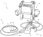
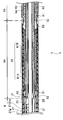
- FIG. 1 is a configuration diagram showing a configuration of an endoscope apparatus according to a first embodiment of the present invention. It is sectional drawing of the insertion part in connection with the 1st Embodiment of this invention. It is a figure for demonstrating a state when the insertion part 101 of the endoscope which does not have the cylindrical elastic part 9 starts to advance along the inner wall W which bent greatly within the test object.
- FIG. 10 is a diagram for explaining a state when the insertion portion 101 of the endoscope that does not have the cylindrical elastic portion 9 further advances along the inner wall that is largely bent in the examination target.
- FIG. 1 is a configuration diagram showing a configuration of an endoscope apparatus according to the present embodiment.
- the endoscope system 1 includes an endoscope 2 and a device main body 3 connected to the endoscope 2.
- the endoscope 2 includes an elongated and flexible insertion portion 4, an operation portion 5 connected to a proximal end portion of the insertion portion 4, and a universal cord 6 extending from the operation portion 5. It is configured.
- the insertion portion 4 includes a distal end rigid portion 7, a bending portion 8, a cylindrical elastic portion 9, and a long flexible tube portion 10 that are arranged in order from the distal end side of the insertion portion 4.
- An operation unit 5 is connected to a proximal end portion of the tube unit 10.
- the bending portion 8 can be bent in, for example, four directions, up, down, left, and right, by operating a joystick 5 a provided in the operation portion 5.
- the operation unit 5 is also provided with various switches for instructing a photographing operation by an imaging element (not shown) provided in the distal end rigid portion 7.
- the apparatus main body 3 has, for example, a box shape, and a monitor that displays an endoscopic image captured by the endoscope 2 is provided on the exterior housing.
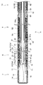
- FIG. 2 is a cross-sectional view of the insertion portion according to the present embodiment.
- the distal end rigid portion 7 provided at the distal end portion of the insertion portion 4 includes a distal end rigid member 11 having a cylindrical shape made of metal or resin.
- An imaging unit 12 and an illumination unit 13 indicated by dotted lines are provided inside the distal end rigid member 11.
- the imaging unit 12 includes an imaging element such as a CCD that receives reflected light from an observation target, and the illumination unit 13 includes a light emitting element such as a light emitting diode (LED) that emits illumination light.
- a cover member 14 is covered on the distal end side of the distal end rigid member 11.
- An observation window and an illumination window are provided on the distal end surface of the distal end rigid member 11, and the imaging unit 12 receives light passing through the observation window, and illumination light from the illumination unit 13 is emitted through the illumination window.
- the imaging unit 12 outputs an imaging signal to the imaging signal cable 15 extending from the base end.
- the illumination unit 13 receives an illumination drive signal via a drive signal cable 16 extending from the base end.
- the bending portion 8 that is provided on the proximal end side of the distal end rigid portion 7 of the insertion portion 4 and bends according to the bending operation in the operation portion is composed of a plurality of annular bending pieces 21. Two adjacent bending pieces 21 are pivotally supported at two points in the radial direction, and the plurality of bending pieces 21 are configured to be bent in the vertical and horizontal directions.
- the proximal end portion of the distal end rigid portion 7 is fixed to the most advanced bending piece 21d of the bending portion 8 with a screw or the like.
- the most proximal bending piece 21p of the bending portion 8 is connected to the distal end portion of the cylindrical joint receiving member 22.
- each bending wire 31 is crimped in a state where the tubular member 31a is covered, and is fixed to the most advanced bending piece 21d.
- the four bending wires 31 are passed through the holes of the plurality of guide members 21g, and are arranged around the axis of the insertion portion 4 at an interval of 90 degrees.
- a rubber tube 41 having elasticity is put on the outer peripheral surface of the curved portion 8.
- the rubber tube 41 is a member for waterproofing the bending portion 8.
- the distal end portion of the rubber tube 41 is wound with a thread (not shown), coated with an adhesive, and is externally fixed to the outer peripheral portion of the most advanced bending piece 21d.
- the proximal end portion of the rubber tube 41 is wound with a thread (not shown), coated with an adhesive, and is externally fixed to the outer peripheral portion of the joint receiving member 22.
- the outer peripheral surface of the curved portion 8 is covered with a tubular mesh tube 42 formed in a tubular shape by knitting a thin metal wire.
- the mesh tube 42 which is a so-called metal blade, covers not only the curved portion 8 but also the tubular elastic portion 9 to the flexible tube portion 10.
- the plurality of connected bending pieces 21 are cylindrical, and the imaging signal cable 15 and the drive signal cable 16 are inserted into the hollow portions inside the plurality of bending pieces 21.
- a coil receiving member 51 on the distal end side is connected to the proximal end portion of the cylindrical joint receiving member 22 and is fixed by an adhesive or welding.
- the coil receiving member 51 has a cylindrical shape, and the distal end portion of the coil receiving member 51 is inserted into the proximal end portion of the joint receiving member 22.
- Each bending wire 31 is inserted through a coil pipe 32.
- the distal end portion of each coil pipe 32 is fixed to the proximal end portion of the bending portion 8.
- the tip of each coil pipe 32 is fixed to the coil receiving member 51 by an adhesive or welding at a point C1 in FIG.
- each bending wire 31 is fixed to the most advanced bending piece 21 d, and the distal end portion of each coil pipe 32 is fixed to the coil receiving member 51. Therefore, when the inspector tilts the joystick 5a in a desired direction, the bending wire 31 corresponding to that direction is pulled or relaxed, so that the bending portion 8 is bent.
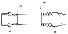
- the step part 51a is formed in the outer peripheral part of the base end side part of the coil receiving member 51 along the circumferential direction.
- the distal end portion of the contact coil 52 is connected to the proximal end portion of the coil receiving member 51 so as to be extrapolated to the cylindrical outer surface formed by the stepped portion 51a, and is fixed by an adhesive, welding, soldering, or the like. Yes.
- the close contact coil 52 is a cylindrical elastic member made of metal such as stainless steel.
- the proximal end portion of the contact coil 52 is connected to the proximal coil receiving member 53 and is fixed by an adhesive, welding, or the like. Specifically, a stepped portion 53 a is formed along the circumferential direction on the outer peripheral portion of the tip side portion of the coil receiving member 53.
- the proximal end portion of the close contact coil 52 is connected to the distal end portion of the proximal end side coil receiving member 53 so as to be extrapolated to the cylindrical outer surface formed by the stepped portion 53a, and is bonded by an adhesive, welding, solder, or the like. It is fixed.
- the coil receiving members 51 and 53 have a cylindrical shape, and the distal end portion of the close contact coil 52 is fitted into a stepped portion 51 a formed on the proximal end side of the coil receiving member 51, and the proximal end of the close contact coil 52 is formed.
- the portion is fitted into a stepped portion 53 a formed on the distal end side of the coil receiving member 53.
- the rubber tube 54 having elasticity is covered on the outer peripheral surfaces of the two coil receiving members 51 and 53 and the close contact coil 52.
- the rubber tube 54 is a member for waterproofing the cylindrical elastic portion 9.
- the distal end portion of the rubber tube 54 is wound with a thread (not shown), coated with an adhesive, and connected to the outer peripheral portion of the joint receiving member 22 and fixed.
- the proximal end portion of the rubber tube 54 is wound around a thread (not shown), coated with an adhesive, and connected and fixed to the outer periphery of the coil receiving member 53.
- the cylindrical elastic portion 9 is configured by the contact coil 52 that is not compressed in the axial direction. Therefore, in the close contact coil 52, the axial length of the cylindrical elastic portion 9 does not shrink in the axial direction of the insertion portion 4.
- the proximal end portion of the coil receiving member 53 is connected to a cylindrical fixing member 61 and fixed by welding or the like.
- the distal end portion of the flexible tube portion 10 is connected to the proximal end side of the fixing member 61 and is fixed by an adhesive or the like.
- the flexible tube portion 10 provided on the proximal end side of the cylindrical elastic portion 9 is made of a metal and is wound so that a belt-like member flex 62 covers the outer periphery of the imaging signal cable 15 and the like.
- the outer peripheral portion of the flex 62 is covered with a metallic net-like member 63 made of metal.
- the outer peripheral surface of the mesh member 63 is covered with a resin member 64.
- the curved tube 8 to the flexible tube 10 are covered with the mesh tube 42.
- the tip of the mesh tube 42 is fixed to the outer peripheral portion of the most advanced bending piece 21d by thread winding, and an adhesive 71 is applied to the portion fixed by thread winding. Also at the connection portion between the cylindrical elastic portion 9 and the flexible tube portion 10, the outer periphery of the mesh tube 42 is wound around and the adhesive 72 is applied.
- the bending resistance R1 of the bending portion 8 when not bending is the cylindrical elasticity. It is lower than the hardness R2 of the portion 9 against bending. And the hardness R2 with respect to the bending of the cylindrical elastic part 9 is lower than the hardness R3 of the flexible tube part 10. That is, the relationship between R1, R2, and R3 satisfies the following formula (1).
- the bending portion 8 when the bending wire 31 is not pulled is easier to bend than the cylindrical elastic portion 9 with respect to bending in four directions (vertical and horizontal directions). Furthermore, the cylindrical elastic part 9 is easier to bend than the flexible tube part 10 with respect to bending in four directions (up, down, left and right directions).
- L1 and L2 are expressed by the following formula ( It is preferable to satisfy 2).
- the length L1 of the cylindrical elastic part 9 and the length L2 of the bending part 8 are equal.
- the cylindrical elastic portion 9 is provided between the bending portion 8 and the flexible tube portion 10, does not bend according to the bending operation in the operation portion, and is higher than the bending strength of the bending portion 8. And it has the hardness with respect to a bending lower than the hardness with respect to the bending of the flexible tube part 10.
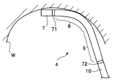
- FIG. 3 is a diagram for explaining a state when the insertion portion 101 of the endoscope that does not have the cylindrical elastic portion 9 starts to advance along the greatly bent inner wall W in the examination target.
- FIG. 4 is a view for explaining a state when the insertion portion 101 of the endoscope that does not have the cylindrical elastic portion 9 further advances along the inner wall that is greatly bent in the inspection object.
- the insertion portion 101 has a bending portion 103 on the proximal end side of the distal end rigid portion 102 and a flexible tube portion 104 on the proximal end side of the bending portion 103.
- the distal rigid portion 102 corresponds to the distal rigid portion 7 described above
- the curved portion 103 corresponds to the curved portion 8 described above
- the flexible tube portion 104 corresponds to the flexible tube portion 10 described above.
- the curvature radius of the curved portion 103 when the distal end rigid portion 102 of the insertion portion 101 starts to advance along the inner wall W is large, and the curved portion 103 is not greatly bent.
- the bending portion 103 is bent so as to be bent as shown in FIG.
- the bending portion 103 When the bending portion 103 is bent so as to be bent, a large bending stress is concentrated on the bent portion. As a result, breakage of a part such as a cable inserted into the insertion portion 101 occurs, the insertion portion is broken, or the inner wall W is an inner wall of a metal pipe, and the outer skin of the insertion portion 101 is strongly rubbed and cut. There is also a fear. Further, when the bending portion 103 is bent so as to be bent, the insertion property of the insertion portion 101 thereafter is also deteriorated.
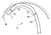
- FIG. 5 is a diagram for explaining a state when the insertion portion 4 of the endoscope 2 according to the present embodiment starts to advance along the greatly bent inner wall W in the inspection target.
- FIG. 6 is a diagram for explaining a state when the insertion portion 4 of the endoscope 2 according to the present embodiment has further advanced along the greatly bent inner wall in the examination target.
- the curvature radius of the bending portion 8 when the distal end rigid portion 7 of the insertion portion 4 starts to advance along the inner wall W is large, and the bending portion 8 is not greatly bent.
- the cylindrical elastic portion 9 is also bent following the bending portion 8 as shown in FIG. It is applied not only to the part 8 but also to the cylindrical elastic part 9. Therefore, both the curved portion 8 and the cylindrical elastic portion 9 bend with a large radius of curvature compared to the radius of curvature of the curved portion 103 of FIG.
- the cylindrical elastic portion 9 becomes a buffer portion that receives the pushing force in a distributed manner, and the bending portion 8 is bent. Since it does not bend greatly, parts such as cables inserted into the insertion portion 4 are broken, the insertion portion is broken, or the inner wall W is an inner wall of a metal pipe, and the outer skin of the insertion portion 4 is strong. It will not rub off and will not break, and the insertability of the curved portion 8 will not deteriorate.
- an endoscope with good insertability of the insertion portion 4 by preventing the bending portion 8 of the insertion portion 4 from bending so that the insertion portion 4 is hardly broken. Can be provided.
- the cylindrical elastic portion of the endoscope according to the first embodiment has the same bending hardness over the entire length in the axial direction, but in the second embodiment, the first elastic portion The bending resistance of the flexible tube portion varies along the axial direction of the insertion portion.
- the present embodiment Since the endoscope of the present embodiment has almost the same configuration as the endoscope of the first embodiment, the same constituent elements are denoted by the same reference numerals. Therefore, the description will be omitted, and different components will be described.
- FIG. 7 is a cross-sectional view of the insertion portion according to the present embodiment.
- a cylindrical elastic portion 9 ⁇ / b> A is arranged between the bending portion 8 and the flexible tube portion 10.
- the cylindrical elastic portion 9 ⁇ / b> A has a contact coil 81.
- the close contact coil 81 includes two close contact coils 81A and 81B formed of wire materials having different wire diameters.
- the close contact coil 81A is disposed on the distal end side of the cylindrical elastic portion 9A, and the close contact coil 81B is disposed on the proximal end side of the tubular elastic portion 9A.
- the proximal end portion of the contact coil 81A and the distal end portion of the contact coil 81B are connected and fixed by welding or the like. Therefore, the hardness of the cylindrical elastic portion 9 ⁇ / b> A with respect to bending differs along the axial direction of the insertion portion 4. Here, the hardness with respect to the bending of the cylindrical elastic portion 9A is increased stepwise along the direction from the distal end portion of the insertion portion 4 to the proximal end portion.
- the hardness R21 of the cylindrical elastic portion 9A with respect to the bending of the close contact coil 81A is lower than the hardness R22 of the cylindrical elastic portion 9A with respect to the bending of the close contact coil 81B. Therefore, the hardness R1 with respect to the bending of the bending portion 8 when not curved, the hardness R21 with respect to the bending of the contact coil 81A of the cylindrical elastic portion 9A, and the portion of the adhesion coil 81B of the cylindrical elastic portion 9A.
- the relationship between the hardness R22 against bending and the hardness R3 of the flexible tube portion 10 satisfies the following expression (3).
- the portion of the close contact coil 81A of the cylindrical elastic portion 9A is easier to bend than the portion of the close contact coil 81B of the cylindrical elastic portion 9A.
- the same effects as those of the first embodiment can be produced, and the bending method in the cylindrical elastic portion 9A can be made more gradual.
- two close-contact coils having different wire diameters are used for the cylindrical elastic portion 9A.
- three or more close-contact coils having different wire diameters may be used. . That is, the contact coil having the smallest wire diameter is disposed on the distal end side of the cylindrical elastic portion 9A, the contact coil having the largest wire diameter is disposed on the proximal end side of the tubular elastic portion 9A, and the distal end of the tubular elastic portion 9A.
- a plurality of close contact coils whose wire diameter increases from the side toward the base end side are used.
- the change in hardness against bending is once in the middle of the cylindrical elastic portion 9A, but three or more closely-contacted coils having different wire diameters are used. May be. In that case, there will be a plurality of discrete changes in hardness due to bending in the middle of the cylindrical elastic portion 9A.
- an adhesive coil formed using a wire whose wire diameter gradually changes may be used for the cylindrical elastic portion 9A.
- FIG. 8 is a schematic cross-sectional view of the cylindrical elastic portion 9B along the axial direction for explaining the configuration of the cylindrical elastic portion 9B having a contact coil formed using a wire whose wire diameter gradually changes. It is.
- the close contact coil 82 is formed using a wire whose wire diameter gradually changes.
- the close contact coil 82 includes a base end portion of the coil receiving member 51 and a coil receiving member 53 so that the wire diameter of the wire increases from the distal end side to the proximal end side of the close contact coil 82. Arranged between the tips.
- the change in hardness against bending is the tip of the cylindrical elastic portion 9A. It changes continuously from the side toward the base end. That is, the hardness with respect to the bending of the cylindrical elastic portions 9, 9 ⁇ / b> A, 9 ⁇ / b> B increases along the direction from the distal end portion of the insertion portion 4 toward the proximal end portion.
- the distal end portion of the close contact coil 82 of the cylindrical elastic portion 9B is similar to the cylindrical elastic portion 9B. It is easier to bend than the proximal end portion of the contact coil 2.
- the bending portion 8 of the insertion portion 4 is not bent so as to be bent, and the insertion portion 4 is hardly broken.
- An endoscope with good insertability can be provided.
- FIG. 9 is a schematic cross-sectional view of the cylindrical elastic portion 9 ⁇ / b> C along the axial direction for explaining the configuration of the cylindrical elastic portion having a rubber member, according to a modification of the first and second embodiments. It is.
- a cylindrical rubber member 83 is disposed between the proximal end portion of the coil receiving member 51 and the distal end portion of the coil receiving member 53.
- the tube-like rubber member 83 has flexibility and elasticity, and therefore produces an effect equivalent to that of the contact coil 52 described above. Further, as shown in FIG. 7, as the wire diameter of the linear member is changed stepwise, the thickness of the thin portion of the rubber member 83 is gradually increased in the middle from the distal end side to the proximal end side. The thickness of the thin portion of the rubber member 83 gradually increases from the distal end side toward the proximal end side, as shown in FIG. 8 or as the wire diameter of the linear member is gradually changed as shown in FIG. It may be changed as follows.
- the hardness against bending may be changed. That is, the hardness with respect to the bending of the cylindrical elastic portion can be changed by changing the wire diameter or material of the linear member constituting the cylindrical elastic portion, or the material of the rubber member.
- the insertion portion is made difficult to be broken so that the bending portion of the insertion portion is not bent so that the insertion portion can be easily inserted.
- An endoscope can be provided.
Landscapes
- Health & Medical Sciences (AREA)
- Life Sciences & Earth Sciences (AREA)
- Surgery (AREA)
- Physics & Mathematics (AREA)
- Optics & Photonics (AREA)
- Engineering & Computer Science (AREA)
- Medical Informatics (AREA)
- General Health & Medical Sciences (AREA)
- Pathology (AREA)
- Nuclear Medicine, Radiotherapy & Molecular Imaging (AREA)
- Biomedical Technology (AREA)
- Heart & Thoracic Surgery (AREA)
- Biophysics (AREA)
- Molecular Biology (AREA)
- Animal Behavior & Ethology (AREA)
- Radiology & Medical Imaging (AREA)
- Public Health (AREA)
- Veterinary Medicine (AREA)
- Astronomy & Astrophysics (AREA)
- General Physics & Mathematics (AREA)
- Multimedia (AREA)
- Signal Processing (AREA)
- Endoscopes (AREA)
- Instruments For Viewing The Inside Of Hollow Bodies (AREA)
Priority Applications (2)
| Application Number | Priority Date | Filing Date | Title |
|---|---|---|---|
| EP14874023.6A EP3087898A4 (en) | 2013-12-24 | 2014-10-09 | Endoscope |
| US15/190,883 US20160306165A1 (en) | 2013-12-24 | 2016-06-23 | Endoscope |
Applications Claiming Priority (2)
| Application Number | Priority Date | Filing Date | Title |
|---|---|---|---|
| JP2013265326A JP2015119839A (ja) | 2013-12-24 | 2013-12-24 | 内視鏡 |
| JP2013-265326 | 2013-12-24 |
Related Child Applications (1)
| Application Number | Title | Priority Date | Filing Date |
|---|---|---|---|
| US15/190,883 Continuation US20160306165A1 (en) | 2013-12-24 | 2016-06-23 | Endoscope |
Publications (1)
| Publication Number | Publication Date |
|---|---|
| WO2015098236A1 true WO2015098236A1 (ja) | 2015-07-02 |
Family
ID=53445577
Family Applications (1)
| Application Number | Title | Priority Date | Filing Date |
|---|---|---|---|
| PCT/JP2014/077044 WO2015098236A1 (ja) | 2013-12-24 | 2014-10-09 | 内視鏡 |
Country Status (5)
| Country | Link |
|---|---|
| US (1) | US20160306165A1 (zh) |
| EP (1) | EP3087898A4 (zh) |
| JP (1) | JP2015119839A (zh) |
| CN (2) | CN204410768U (zh) |
| WO (1) | WO2015098236A1 (zh) |
Cited By (2)
| Publication number | Priority date | Publication date | Assignee | Title |
|---|---|---|---|---|
| FR3047886A1 (fr) * | 2016-02-18 | 2017-08-25 | Axess Vision Tech | Dispositif medical avec une tete distale a encombrement limite |
| WO2020218404A1 (ja) * | 2019-04-25 | 2020-10-29 | 国立大学法人大阪大学 | カテーテルおよびそれを備える軟性内視鏡 |
Families Citing this family (7)
| Publication number | Priority date | Publication date | Assignee | Title |
|---|---|---|---|---|
| JP2015119839A (ja) * | 2013-12-24 | 2015-07-02 | オリンパス株式会社 | 内視鏡 |
| JP6378120B2 (ja) * | 2015-03-19 | 2018-08-22 | Hoya株式会社 | 内視鏡挿入部の湾曲部構造 |
| WO2017216835A1 (ja) * | 2016-06-13 | 2017-12-21 | オリンパス株式会社 | 医療用デバイス |
| CN108303794B (zh) * | 2017-01-12 | 2020-06-16 | 台湾先进医学科技股份有限公司 | 内视镜转向结构 |
| CN109224248A (zh) * | 2018-11-09 | 2019-01-18 | 苏州新光维医疗科技有限公司 | 输尿管导管结构 |
| KR20220143818A (ko) * | 2019-12-19 | 2022-10-25 | 노아 메디컬 코퍼레이션 | 모듈식 내시경용의 시스템 및 방법 |
| WO2024077922A1 (zh) * | 2023-04-21 | 2024-04-18 | 深圳市星辰海医疗科技有限公司 | 内窥镜的先端弯曲区段及一种内窥镜 |
Citations (10)
| Publication number | Priority date | Publication date | Assignee | Title |
|---|---|---|---|---|
| JPS6422641U (zh) | 1987-08-01 | 1989-02-06 | ||
| JPH02131738A (ja) * | 1988-08-18 | 1990-05-21 | Olympus Optical Co Ltd | 内視鏡用可撓管およびその製造方法 |
| JPH1156763A (ja) * | 1997-08-21 | 1999-03-02 | Olympus Optical Co Ltd | 内視鏡 |
| JPH11155871A (ja) * | 1997-12-02 | 1999-06-15 | Fuji Photo Optical Co Ltd | 内視鏡用処置具 |
| JP2001321324A (ja) * | 2000-05-15 | 2001-11-20 | Asahi Optical Co Ltd | 内視鏡用可撓管 |
| JP2001333883A (ja) * | 2000-05-26 | 2001-12-04 | Asahi Optical Co Ltd | 内視鏡用可撓管 |
| JP2006218231A (ja) * | 2005-02-14 | 2006-08-24 | Olympus Corp | 内視鏡用可撓管及び内視鏡装置 |
| JP2011152361A (ja) * | 2010-01-28 | 2011-08-11 | Olympus Corp | 内視鏡の可撓管部と、この可撓管部を有する内視鏡 |
| JP2012055569A (ja) * | 2010-09-10 | 2012-03-22 | Fujifilm Corp | 内視鏡 |
| JP2012231886A (ja) * | 2011-04-28 | 2012-11-29 | Olympus Corp | 内視鏡の可撓管部と、この可撓管部を有する内視鏡 |
Family Cites Families (13)
| Publication number | Priority date | Publication date | Assignee | Title |
|---|---|---|---|---|
| JPS63154151A (ja) * | 1986-12-18 | 1988-06-27 | オリンパス光学工業株式会社 | 内視鏡 |
| JPH02143902A (ja) * | 1988-11-25 | 1990-06-01 | Nec Kansai Ltd | 磁気ヘッドチップの製造方法 |
| JPH074002Y2 (ja) * | 1989-05-10 | 1995-02-01 | 富士写真光機株式会社 | 内視鏡の湾曲部 |
| JP3181331B2 (ja) * | 1991-10-04 | 2001-07-03 | 株式会社町田製作所 | 内視鏡 |
| JP4772208B2 (ja) * | 2001-05-10 | 2011-09-14 | オリンパス株式会社 | 内視鏡 |
| JP4323441B2 (ja) * | 2005-02-14 | 2009-09-02 | オリンパス株式会社 | 内視鏡 |
| JP2007054125A (ja) * | 2005-08-22 | 2007-03-08 | Olympus Medical Systems Corp | 内視鏡 |
| JP5085309B2 (ja) * | 2007-12-26 | 2012-11-28 | オリンパスメディカルシステムズ株式会社 | 内視鏡 |
| EP2457491B1 (en) * | 2010-03-15 | 2014-10-15 | Olympus Medical Systems Corp. | Endoscope |
| EP2564756B1 (en) * | 2010-04-26 | 2017-11-01 | Olympus Corporation | Endoscope |
| CN105011893B (zh) * | 2011-02-16 | 2017-07-11 | 奥林巴斯株式会社 | 内窥镜及处理器具 |
| JP5211271B2 (ja) * | 2011-03-25 | 2013-06-12 | オリンパスメディカルシステムズ株式会社 | 内視鏡 |
| JP2015119839A (ja) * | 2013-12-24 | 2015-07-02 | オリンパス株式会社 | 内視鏡 |
-
2013
- 2013-12-24 JP JP2013265326A patent/JP2015119839A/ja active Pending
-
2014
- 2014-10-09 EP EP14874023.6A patent/EP3087898A4/en not_active Withdrawn
- 2014-10-09 WO PCT/JP2014/077044 patent/WO2015098236A1/ja active Application Filing
- 2014-12-24 CN CN201420833827.6U patent/CN204410768U/zh not_active Expired - Fee Related
- 2014-12-24 CN CN201410818040.7A patent/CN104720732B/zh active Active
-
2016
- 2016-06-23 US US15/190,883 patent/US20160306165A1/en not_active Abandoned
Patent Citations (10)
| Publication number | Priority date | Publication date | Assignee | Title |
|---|---|---|---|---|
| JPS6422641U (zh) | 1987-08-01 | 1989-02-06 | ||
| JPH02131738A (ja) * | 1988-08-18 | 1990-05-21 | Olympus Optical Co Ltd | 内視鏡用可撓管およびその製造方法 |
| JPH1156763A (ja) * | 1997-08-21 | 1999-03-02 | Olympus Optical Co Ltd | 内視鏡 |
| JPH11155871A (ja) * | 1997-12-02 | 1999-06-15 | Fuji Photo Optical Co Ltd | 内視鏡用処置具 |
| JP2001321324A (ja) * | 2000-05-15 | 2001-11-20 | Asahi Optical Co Ltd | 内視鏡用可撓管 |
| JP2001333883A (ja) * | 2000-05-26 | 2001-12-04 | Asahi Optical Co Ltd | 内視鏡用可撓管 |
| JP2006218231A (ja) * | 2005-02-14 | 2006-08-24 | Olympus Corp | 内視鏡用可撓管及び内視鏡装置 |
| JP2011152361A (ja) * | 2010-01-28 | 2011-08-11 | Olympus Corp | 内視鏡の可撓管部と、この可撓管部を有する内視鏡 |
| JP2012055569A (ja) * | 2010-09-10 | 2012-03-22 | Fujifilm Corp | 内視鏡 |
| JP2012231886A (ja) * | 2011-04-28 | 2012-11-29 | Olympus Corp | 内視鏡の可撓管部と、この可撓管部を有する内視鏡 |
Non-Patent Citations (1)
| Title |
|---|
| See also references of EP3087898A4 |
Cited By (3)
| Publication number | Priority date | Publication date | Assignee | Title |
|---|---|---|---|---|
| FR3047886A1 (fr) * | 2016-02-18 | 2017-08-25 | Axess Vision Tech | Dispositif medical avec une tete distale a encombrement limite |
| WO2020218404A1 (ja) * | 2019-04-25 | 2020-10-29 | 国立大学法人大阪大学 | カテーテルおよびそれを備える軟性内視鏡 |
| JP2020178937A (ja) * | 2019-04-25 | 2020-11-05 | 国立大学法人大阪大学 | カテーテルおよびそれを備える軟性内視鏡 |
Also Published As
| Publication number | Publication date |
|---|---|
| JP2015119839A (ja) | 2015-07-02 |
| CN104720732A (zh) | 2015-06-24 |
| EP3087898A1 (en) | 2016-11-02 |
| US20160306165A1 (en) | 2016-10-20 |
| EP3087898A4 (en) | 2017-08-23 |
| CN104720732B (zh) | 2018-05-29 |
| CN204410768U (zh) | 2015-06-24 |
Similar Documents
| Publication | Publication Date | Title |
|---|---|---|
| WO2015098236A1 (ja) | 内視鏡 | |
| JP5355824B1 (ja) | 樹脂チューブ及び内視鏡 | |
| US20130046144A1 (en) | Flexible tube unit of endoscope and endoscope having this flexible tube unit | |
| AU2006213225A1 (en) | Flexible tube for endoscope, and endoscope device | |
| US20130331651A1 (en) | Flexible tube portion of endoscope and endoscope having this flexible tube portion | |
| US20180263469A1 (en) | Endoscope system | |
| EP3269292A1 (en) | Endoscope | |
| EP3135182A1 (en) | Endoscope bending section and endoscope | |
| US9872607B2 (en) | Endoscope | |
| US10813537B2 (en) | Shape detection device | |
| JP2008206699A (ja) | 内視鏡の湾曲操作用条体及びその製造方法 | |
| US20090299139A1 (en) | Endoscope | |
| US9661993B2 (en) | Endoscope | |
| JP6261835B1 (ja) | 内視鏡の可撓管 | |
| US10799091B2 (en) | Endoscope with mesh tube | |
| WO2017122330A1 (ja) | 形状測定筒状可撓体装置 | |
| JP4504076B2 (ja) | 内視鏡 | |
| JP2011120687A (ja) | 内視鏡挿入部 | |
| JP6402285B1 (ja) | 内視鏡 | |
| US20170231468A1 (en) | Endoscope flexible tube and method of manufacturing endoscope flexible tube | |
| WO2018207514A1 (ja) | 内視鏡 | |
| WO2018066274A1 (ja) | 内視鏡 | |
| JP2017225746A (ja) | 内視鏡 | |
| JP2011200357A (ja) | 内視鏡 |
Legal Events
| Date | Code | Title | Description |
|---|---|---|---|
| 121 | Ep: the epo has been informed by wipo that ep was designated in this application |
Ref document number: 14874023 Country of ref document: EP Kind code of ref document: A1 |
|
| NENP | Non-entry into the national phase |
Ref country code: DE |
|
| REEP | Request for entry into the european phase |
Ref document number: 2014874023 Country of ref document: EP |
|
| WWE | Wipo information: entry into national phase |
Ref document number: 2014874023 Country of ref document: EP |