WO2015098098A1 - 車両用空調ユニット - Google Patents
車両用空調ユニット Download PDFInfo
- Publication number
- WO2015098098A1 WO2015098098A1 PCT/JP2014/006410 JP2014006410W WO2015098098A1 WO 2015098098 A1 WO2015098098 A1 WO 2015098098A1 JP 2014006410 W JP2014006410 W JP 2014006410W WO 2015098098 A1 WO2015098098 A1 WO 2015098098A1
- Authority
- WO
- WIPO (PCT)
- Prior art keywords
- air
- fan
- ventilation path
- conditioning unit
- ventilation
- Prior art date
- Legal status (The legal status is an assumption and is not a legal conclusion. Google has not performed a legal analysis and makes no representation as to the accuracy of the status listed.)
- Ceased
Links
Images


Classifications
-
- B—PERFORMING OPERATIONS; TRANSPORTING
- B60—VEHICLES IN GENERAL
- B60H—ARRANGEMENTS OF HEATING, COOLING, VENTILATING OR OTHER AIR-TREATING DEVICES SPECIALLY ADAPTED FOR PASSENGER OR GOODS SPACES OF VEHICLES
- B60H1/00—Heating, cooling or ventilating [HVAC] devices
- B60H1/00457—Ventilation unit, e.g. combined with a radiator
- B60H1/00471—The ventilator being of the radial type, i.e. with radial expulsion of the air
-
- B—PERFORMING OPERATIONS; TRANSPORTING
- B60—VEHICLES IN GENERAL
- B60H—ARRANGEMENTS OF HEATING, COOLING, VENTILATING OR OTHER AIR-TREATING DEVICES SPECIALLY ADAPTED FOR PASSENGER OR GOODS SPACES OF VEHICLES
- B60H1/00—Heating, cooling or ventilating [HVAC] devices
- B60H1/00007—Combined heating, ventilating, or cooling devices
- B60H1/00021—Air flow details of HVAC devices
- B60H1/00035—Air flow details of HVAC devices for sending an air stream of uniform temperature into the passenger compartment
- B60H1/0005—Air flow details of HVAC devices for sending an air stream of uniform temperature into the passenger compartment the air being firstly cooled and subsequently heated or vice versa
-
- B—PERFORMING OPERATIONS; TRANSPORTING
- B60—VEHICLES IN GENERAL
- B60H—ARRANGEMENTS OF HEATING, COOLING, VENTILATING OR OTHER AIR-TREATING DEVICES SPECIALLY ADAPTED FOR PASSENGER OR GOODS SPACES OF VEHICLES
- B60H1/00—Heating, cooling or ventilating [HVAC] devices
- B60H1/00007—Combined heating, ventilating, or cooling devices
- B60H1/00021—Air flow details of HVAC devices
- B60H2001/00078—Assembling, manufacturing or layout details
- B60H2001/00107—Assembling, manufacturing or layout details characterised by the relative position of the heat exchangers, e.g. arrangements leading to a curved airflow
Definitions
- the present disclosure relates to a vehicle air conditioning unit that blows air-conditioned air into a vehicle interior.
- Patent Document 1 includes a first air outlet and a second air outlet, and the temperature of the first air blown from the first air outlet and the second air blown from the second air outlet.
- An air conditioning unit for a vehicle that can perform air conditioning so that a temperature difference occurs between the temperature and the temperature of the vehicle is disclosed.
- the vehicular air conditioning unit of Patent Literature 1 includes a blower case having a scroll portion that houses a centrifugal fan, in addition to the first air outlet and the second air outlet.
- the air outlet of the blower case is connected to each of the first air outlet and the second air outlet.
- the cool air out of the air flowing out from the air discharge port is guided to the first air outlet by the outlet switching damper, and the first air outlet is made to function as the cold air outlet.
- Hot air in the air flowing out from the air discharge port is guided to the second air outlet by the outlet switching damper, and the second air outlet is made to function as the hot air outlet.
- the present disclosure aims to provide a vehicle air conditioning unit capable of suppressing temperature unevenness of air blown from one air outlet.
- the vehicle air conditioning unit includes a ventilation portion in which a first ventilation path having a first downstream end and air flowing toward the first downstream end is formed, and in the first ventilation path. And a temperature adjusting unit that is arranged upstream of the first downstream end and generates a temperature distribution in the air flow in the first ventilation path, an air inlet port through which air flows from the first downstream end, and air is blown out
- a fan case portion formed with a first air outlet, and a plurality of blades that are housed in the fan case portion and around a predetermined fan axis, and that rotate around the fan axis.
- a centrifugal fan that blows out the air sucked from the air suction port to the first air outlet.
- the temperature adjusting unit is arranged so that the air flowing into one of the two has a higher temperature than the air flowing into the other.
- the temperature adjustment unit With such an arrangement of the temperature adjustment unit, at least part of the angular range expected from the fan axis flows into one of the inner region and the outer region at the air suction port of the fan case unit. Air becomes hotter than the air flowing into the other. Therefore, for at least a part of the angle range, both hot air and cold air flow between the blades of the centrifugal fan. Thereby, the air blown out between the rotating blades is well mixed, and the temperature unevenness of the air blown out from the air blowout port can be suppressed.
- FIG. 2 is a cross-sectional view taken along line II-II in FIG.
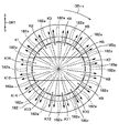
- FIG. 3 is a cross-sectional view taken along line III-III in FIG. It is the figure which looked at the air blower from the same direction as FIG. 3 in 1st Embodiment, Comprising: It is the figure which showed temperature distribution of the air suction inlet. It is a figure which shows the correspondence of the angle range seen from a fan axial center, and the adjacent pair of the fan blade in which the air of each angle range enters. It is sectional drawing which showed typically the vehicle air conditioning unit of 2nd Embodiment. It is sectional drawing in the VII-VII line of FIG.
- FIG. 15 is a cross-sectional view taken along line XV-XV in FIG. It is sectional drawing which showed typically the air conditioning unit of 7th Embodiment. It is sectional drawing in the XVII-XVII line of FIG. It is a perspective view of the ventilation part which the air-conditioning unit of 7th Embodiment has. It is sectional drawing which showed typically the modification of the air conditioning unit of 5th Embodiment, Comprising: It is a figure corresponded in FIG. It is sectional drawing in the XX-XX line of FIG.
- FIG. 11 is a detailed view of the XXI portion of FIG.
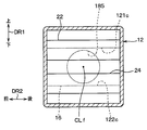
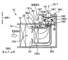
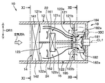
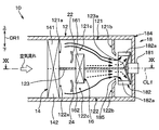
- FIG. 1 is a cross-sectional view schematically showing a vehicle air conditioning unit 10 of the present embodiment.
- the vehicle air-conditioning unit 10 (hereinafter simply referred to as the air-conditioning unit 10) is disposed in a front portion of the vehicle interior, and is for a vehicle including a refrigeration cycle including, for example, a compressor and a condenser disposed in an engine room. Part of the air conditioner.
- the arrow DR1 which shows the up-down direction of FIG. 1 has shown the up-down direction in the vehicle mounting state of the air conditioning unit 10.
- the vehicle vertical direction which is the vertical direction in the vehicle mounted state, is simply referred to as the vertical direction
- the direction orthogonal to the vehicle vertical direction is simply referred to as the horizontal direction.
- the air conditioning unit 10 includes a ventilation section 12, an evaporator 14, a heater core 16, a blower 18, and a plurality of doors for switching the air flow in the ventilation section 12.
- the ventilation part 12 is made of, for example, resin and has a cylindrical shape extending in the horizontal direction.
- the ventilation path 120 (corresponding to an example of the first ventilation path) inside the ventilation part 12 is Air to be cooled or heated flows.
- the ventilation path 120 has an upstream end 120 a corresponding to a position immediately after the evaporator 14 and a downstream end 120 b (corresponding to an example of a first downstream end) corresponding to a position immediately before the blower 18. Outside air that is outside the passenger compartment or inside air that is inside the passenger compartment passes through the evaporator 14 and then flows into the ventilation path 120 from the upstream end 120a and flows through the ventilation path 120 toward the downstream end 120b.
- the evaporator 14 is a cooling heat exchanger that cools the air by exchanging heat between the refrigerant flowing through the inside and the air passing through the evaporator 14, and each of the first ventilation path 121 and the second ventilation path 122.
- the cooling part which cools the air which flows into is comprised.
- the shape of the evaporator is a rectangular parallelepiped shape.
- the evaporator 14 is installed in the ventilation part 12 and is provided on the upstream side of the air flow with respect to the ventilation path 120.
- the direction in which air passes through the evaporator 14 is the left-right direction in FIG.
- the evaporator 14 cools the air flowing into the ventilation path 120 and flowing through the ventilation path 120.
- the evaporator 14 is provided so as to cover the entire ventilation path 120 on the upstream side of the air flow at the upstream end 120a, whereby the air flowing into the upstream end 120a bypasses the evaporator 14. Without being cooled, the evaporator 14 flows into the upstream end 120a.
- the heater core 16 shown in FIG. 1 is a rectangular parallelepiped heating heat exchanger that heats air by exchanging heat between engine cooling water, which is hot water flowing through the heater core, and air passing through the heater core 16.
- the direction in which air passes through the heater core 16 is the left-right direction in FIG.
- the heater core 16 is disposed between the upstream end 120 a and the downstream end 120 b in the ventilation path 120, and heats the air cooled by the evaporator 14.
- the ventilation path 120 includes a first bypass path 121c and a second bypass path 122c that allow the air cooled by the evaporator 14 to bypass the heater core 16 and flow to the downstream end 120b.
- solid arrows indicating the air flow indicate the flow of cold air that is cooled by the evaporator 14 and bypasses the heater core 16.
- a broken-line arrow indicating an air flow indicates a flow of warm air that passes through the heater core 16 and is heated by the heater core 16. This also applies to FIGS. 5, 6, 8, and 9 described later.
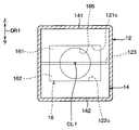
- the heater core 16 is provided so as to be located in the central portion of the ventilation path 120 when viewed in the fan axis CLf direction as shown in FIG. That is, an imaginary line extending straight from the fan axis CLf penetrates the inside (more specifically, the center) of the heater core 16 instead of the periphery.
- the heater core 16 When the heater core 16 and the air passage 120, which is an air passage, are viewed from the fan axial direction, the heater core 16 has both ends in the vehicle front-rear direction (left-right direction in FIG. 2) reaching the air passage end.
- the first bypass passage 121 c is formed only on the upper side with respect to the heater core 16.
- the second bypass path 122c is formed only on the lower side with respect to the heater core 16 and separated from the first bypass path 121c.
- a first air mix door 22 and a second air mix door 24 are provided between the upstream end 120a and the heater core 16 in the ventilation path 120 shown in FIG.
- Each of the air mix doors 22 and 24 is an air mix door provided in a general vehicle air conditioning unit, and specifically, is a sliding door that slides along an arcuate locus.
- the air mix doors 22, 24 are air volume ratio adjusting devices that adjust the air volume ratio between the air volume flowing through the first bypass path 121 c or the second bypass path 122 c and the air volume flowing through the heater core 16.
- the air mix doors 22 and 24 are continuously displaced by an actuator connected to the air mix doors 22 and 24. Specifically, the air mix doors 22, 24 are displaced from the max cool position to the max hot position. In the max cool position, the air mix doors 22 and 24 block the air flow to the heater core 16 to maximize the air flow to the first bypass passage 121c and the second bypass passage 122c. In the maximum hot position, the air mix doors 22 and 24 maximize the air flow to the heater core 16 and block the air flow to the first bypass passage 121c and the second bypass passage 122c.
- the evaporator 14, the heater core 16, and the air mix doors 22 and 24 correspond to an example of a temperature adjustment unit that generates a temperature distribution in the air flow in the ventilation path 120 as a whole.
- the blower 18 is a centrifugal multiblade blower, that is, a sirocco fan.
- the blower 18 includes an electric motor 181, a centrifugal fan 182 that is driven by the electric motor 181 and rotates around a predetermined fan axis CLf, and a fan case portion 184 that accommodates the centrifugal fan 182. .
- the blower 18 is arranged such that the fan axis CLf is parallel to the air flow direction of the ventilation path 120 (longitudinal direction of the ventilation path 120).
- the axial direction of the fan shaft center CLf is abbreviated as the fan shaft center CLf direction.
- the fan case portion 184 is made of, for example, resin, and is integrally formed with the ventilation portion 12 by injection molding or the like.
- the fan case unit 184 and the ventilation unit 12 together form an air conditioning case that is a casing of the air conditioning unit 10.
- an air inlet 185 shown in FIG. 1 and one air outlet 188 (corresponding to an example of a first air outlet) shown in FIGS. 1 and 3 are formed.
- the fan case part 184 is a scroll casing generally used in a sirocco fan. Accordingly, in the fan case portion 184, the air sucked into the fan case portion 184 from the air suction port 185 is blown out of the fan case portion 184 from the air outlet 188.
- the air suction port 185 is a hole that faces the blower 18 and opens in a circular shape with the fan shaft center CLf as a central axis. As shown in FIG. 1, one side of the fan case portion 184 in the direction of the fan shaft center CLf, that is, It is formed so as to open to the ventilation portion 12 side.
- the opening diameter of the air suction port 185 is smaller than the outer diameter of the centrifugal fan 182.
- the air outlet 188 is connected to an outlet (for example, a face outlet, a foot outlet, and a defroster outlet) to the vehicle interior via a duct (not shown) connected to the air outlet 188.
- an outlet for example, a face outlet, a foot outlet, and a defroster outlet
- the fan case part 184 which is a scroll casing is provided with the internal peripheral surface 184a and the nose part 184b, as shown in FIG.
- the inner peripheral surface 184 a is arranged on the radially outer side of the centrifugal fan 182 and is curved in the same direction as the outer periphery of the centrifugal fan 182.
- the first inner peripheral surface 184a forms an air passage 18a curved along the outer periphery of the centrifugal fan 182 with the centrifugal fan 182 in the radial direction of the centrifugal fan 182.
- air passage 18a air flows in the same direction as the rotation direction DRrv of the centrifugal fan 182, and the air passage 18a is connected to the air outlet 188 on the downstream side of the air passage 18a.
- the winding start portion 184e of the inner peripheral surface 184a is located at the end of the air passage 18a on the upstream side of the air flow, and is a portion where the involute curve starts.
- the nose portion 184b is formed in the winding start portion 184e of the inner peripheral surface 184a.
- the nose part 184b has comprised the convex shape which swelled inside the fan case part 184.
- the winding start portion 184e of the inner peripheral surface 184a is a starting portion of the inner peripheral surface 184a in the rotation direction according to the rotation direction DRrv of the centrifugal fan 182.
- the centrifugal fan 182 is a centrifugal multiblade fan provided in a general air conditioning unit for vehicles, and rotates around the fan axis CLf.
- the rotation direction of the centrifugal fan 182 is the direction indicated by the arrow DRrv in FIG.
- Centrifugal fan 182 includes plate-like blades 182a (see FIGS. 1 and 5) arranged in a large number around fan axis CLf.
- the centrifugal fan 182 is rotationally driven by the electric motor 181 to suck into the centrifugal fan 182 from the air suction port 185 shown in FIG. 3, and the sucked air is an air passage 18 c (first first) around the centrifugal fan 182. Each of them is blown out to an air passage). That is, the centrifugal fan 182 blows out the air sucked from the air suction port 185 to the air outlet 188 via the air passage 18c.
- the first air mix door 22 and the second air mix door 24 are at an intermediate position between the max cool position and the max hot position as shown in FIG.
- the air from the evaporator 14 flows through the heater core 16, the first bypass passage 121c, and the second bypass passage 122c.
- the cool air that bypasses the heater core 16 and the warm air heated by the heater core 16 are mixed to a certain extent.
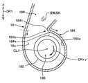
- the warm air heated by the heater core 16 mainly occupies the inner region 185 p of the air suction port 185. Further, as a region other than the inner region 185p, cold air that bypasses the heater core 16 mainly occupies the first outer region 185q and the second outer region 185r above and below the inner region 185p.
- the shape of the inner region 185p corresponds to the shape of the heater core 16, and has a belt shape whose longitudinal direction coincides with the vehicle longitudinal direction DR2 when the vehicle is mounted.
- the inner region 185p includes the fan axis CLf (more specifically, one point on an imaginary line obtained by extending the fan axis straight) inside, not at the periphery.
- first outer region 185q and the second outer region 185r correspond to the shapes of the first bypass passage 121c and the second bypass passage 122c, respectively.
- the outer regions 185q and 185r do not include the fan axis CLf (more specifically, one point on an imaginary line obtained by extending the fan axis straightly).
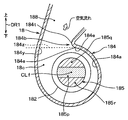
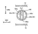
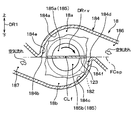
- FIG. 4 is a view of the blower 18 viewed from the same direction as FIG. 3, and shows the temperature distribution of the air suction port 185.
- the air flowing into the air suction port 185 in the vicinity of the fan shaft center CLf, temperature unevenness in the circumferential direction around the fan shaft center CLf is suppressed.
- the air flowing into the air suction port 185 has a temperature gradient in the radial direction of the fan shaft center CLf within a specific angle range expected from the fan shaft center CLf, and is close to the center of the air suction port 185. The temperature distribution becomes higher.
- the air flowing into the air suction port 185 differs in the degree of entering into the centrifugal blower 18 depending on the distance from the fan shaft center CLf at the air suction port 185.
- the air that flows into the air suction port 185 from a position closer to the fan shaft center CLf is further away from the centrifugal fan 18 (the air suction port 185 in the direction of the fan shaft center CLf).
- the air flows between the blades 182a with a bias toward the opposite side.
- the air that flows into the air suction port 185 from a position farther from the fan axis CLf is closer to the front side of the centrifugal blower 18 (air in the direction of the fan axis CLf).
- the air flows between the blades 182a with a bias toward the suction port 185 side.
- any adjacent pair of all the fan blades 182a can have various distances from the fan axis CLf between the adjacent fan blades 182a.
- the air flowing into the air suction port 185 flows.
- the adjacent pair refers to two adjacent fan blades 182a. That is, between any adjacent pair of fan blades 182a, the air flowing into the air suction port 185 at a position close to the fan shaft center CLf and the air flowing into the air suction port 185 at a position far from the fan shaft center CLf are: Inflow.
- the air that has flowed into the air suction port 185 in the angle range K1 viewed from the fan axis CLf includes the warm air in the inner region 185p and the cool air in the first outer region 185q. Flow into. Thereby, in the air which blows off between the adjacent pairs which rotate, warm air and cold air are well mixed. The same applies to each of the angle ranges K2 to K6.
- the air that has flowed into the air suction port 185 in the angle range K9 viewed from the fan axis CLf includes warm air in the inner region 185p and cold air in the second outer region 185r, and flows between the same adjacent pairs. Thereby, in the air which blows off between the adjacent pairs which rotate, warm air and cold air are well mixed. The same applies to each of the angle ranges K10 to K14.
- the air suction port 185 of the fan case portion 184 is used for air suction by the arrangement of the evaporator 14, the heater core 16, the first air mix door 22, and the second air mix door 24, which are temperature control units.
- the inner region 185p including the fan shaft center CLf of the opening 185 and the outer regions 185q and 185r not including the fan shaft center CLf air flowing into one (specifically, the inner region 185p) flows into the other. It becomes hotter than air.
- the air blown out from the adjacent pair may contain only warm air because the heater core 16 has both ends in the vehicle front-rear direction (left-right direction in FIG. 2). This is because it reaches the end of the ventilation path 120, that is, the ventilation section 12.
- the configuration as in the present embodiment has an effect that the heater core 16 can be instructed by a simple method of fixing the heater core 16 to the ventilation portion 12.
- the heater core 16 can be almost completely prevented from passing air during the max cool, and almost all the air can pass through the heater core 16 during the max hot. Can do.
- the longitudinal direction of the heater core 16 that is, the direction reaching the ventilation portion 12 (the left-right direction in FIG. 2)
- the connection portion 185z connection portion between the air passage 18c and the air outlet 188) viewed from the fan axis CLf.
- the angle range does not match or overlap.
- the connecting portion 185z is defined as a plane connecting the winding start portion 184e where the involute curve starts on the inner peripheral surface 184a and the portion 184y where the involute curve ends.
- the air suction port 185 has an angular range K7, K8, K15 other than the at least some of the angular ranges K1 to K6 and K9 to K14 out of the angular range expected from the fan axis CLf.
- K16 is out of an angular range in which the connecting portion 185z is viewed from the fan axis CLf.
- the cool air that hardly mixed with the warm air in the adjacent pair by flowing into the blower 18 from the angle ranges K7, K8, K15, and K16 at the air suction port 185 does not change the direction after leaving the centrifugal fan 182.
- the air outlet 188 does not enter directly. That is, the air outlet 188 is always entered after changing the direction. Accordingly, since the possibility of mixing with other air increases while changing the direction, the temperature unevenness of the air blown out from the air outlet 188 can be further suppressed.
- the air conditioning unit 10 can be easily configured as compared with a configuration having a plurality of heater cores or evaporators in one ventilation path.
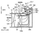
- FIG. 6 is a cross-sectional view schematically showing the air conditioning unit 10 of the present embodiment, and corresponds to FIG. 1 of the first embodiment.
- the air conditioning unit 10 of the present embodiment includes a hot air duct 26 provided in the ventilation path 120 in addition to the configuration of the first embodiment.
- the warm air duct 26 is formed in the ventilation path 120 from the heater core 16 to the air suction port 185, and forms a passage for guiding the air flowing out from the heater core 16 to the blower 18.
- the heater core 16 is arranged at the upstream end of the air flow of the hot air duct 26. That is, as in the first embodiment, the heater core 16 is such that the air (hot air) flowing into the inner region 185p has a higher temperature than the air (cold air) flowing into the first outer region 185q and the second outer region 185r. Is arranged.
- the hot air duct 26 has a first partition plate 26a and a second partition plate 26b both made of resin.
- the first partition plate 26a has an end portion of the ventilation path 120, that is, the ventilation passage at both ends in the left-right direction (direction perpendicular to the paper surface of FIG. 6) from the end portion on the heater core 16 side to the end portion on the air suction port 185 side. It has reached part 12.
- the second partition plate 26b also extends from the end on the heater core 16 side to the end on the air suction port 185 side at both ends in the left-right direction (direction perpendicular to the paper surface of FIG. 6). Part, that is, the ventilation part 12 is reached.
- the warm air duct 26 is configured by the first partition plate 26 a, the second partition plate 26 b, and the ventilation portion 12, whereby the warm air in the warm air duct 26 and the heater core are formed in the ventilation path 120.
- the cold wind that bypasses 16 is not mixed.
- the hot air duct 26 guides the warm air flowing out from the heater core 16 to the inner region 185p by the inner wall surface, and, if viewed in the opposite direction, the cool air bypassing the heater core 16 by the outer wall surface is transferred to the outer region 185q. , 185r.
- the blower 18 is disposed so that the fan axis CLf faces the horizontal direction.
- the blower 18 has the fan axis CLf in the vertical direction DR1. It is arranged to face.
- the air suction port 185 faces the blower 18 at the upper end surface of the ventilation portion and opens in a circular shape with the fan axis CLf as the central axis.
- the warm air duct 26 (more specifically, the partition plates 26a and 26b) reaches the end of the air suction port 185 at both ends in the vehicle longitudinal direction DR2. Yes.
- the longitudinal direction (vehicle longitudinal direction DR2) in which the inner region 185p extends to the end of the air suction port 185, and the direction of the air outlet 188 as viewed from the fan axis CLf of the blower 18 (vehicle lateral direction) DR3) does not coincide with each other, and the deviation in both directions is 45 ° or more and less than 135 °, more specifically, approximately 90 °. Therefore, as in the first embodiment, the cool air that hardly mixed with the warm air in the adjacent pair does not directly enter the air outlet 188 without changing the direction after leaving the centrifugal fan 182. That is, the air outlet 188 is always entered after changing the direction. Accordingly, since the possibility of mixing with other air increases while changing the direction, the temperature unevenness of the air blown out from the air outlet 188 can be further suppressed.
- the air conditioning unit 10 of the present embodiment is different from the air conditioning unit 10 of the first embodiment in the air inlet 185 side of the first partition plate 26 a and the second partition plate 26 b of the hot air duct 26. Is changed so as not to reach the air inlet 185.
- the second implementation is performed at the air suction port 185. It is possible to realize a temperature distribution substantially equivalent to the form.
- the hot air duct 26 guides the flow of the hot air through the heater core 16 so that the inner region 185p mainly occupied by the warm air and the outer regions 185q and 185r mainly occupied by the cold air are formed in the air inlet 185. It only has to be.
- the pressure loss of the warm air inside the hot air duct 26 and the cold air outside the hot air duct 26 is reduced by the length of the warm air duct 26, and the warm air The amount of material of the duct 26 can be reduced.
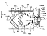
- FIG. 9 A fourth embodiment will be described. As shown in FIG. 9, the air conditioning unit 10 of the present embodiment separates the evaporator 14 in the vertical direction DR1 into the two evaporators 14 a and 14 b and the heater core 16 in the vertical direction with respect to the air conditioning unit 10 of the first embodiment. DR1 is separated into two heater cores 16a and 16b.
- the evaporators 14a and 14b and the heater cores 16a and 16b are inclined with respect to the air flow direction in the air passage 120 (the left-right direction in FIG. 9). Specifically, the evaporators 14a and 14b are inclined so that the interval between the evaporator 14a and the evaporator 14b increases from the upstream side to the downstream side in the air flow direction in the ventilation path 120. Further, the heater cores 16a and 16b are inclined so that the space between the heater core 16a and the heater core 16b increases from the upstream side to the downstream side in the air flow direction in the ventilation path 120.
- first air mix door 22 is inclined in the same manner as the heater core 16a so as to adjust the air volume ratio between the air volume flowing through the first bypass passage 121c and the air volume flowing into the heater core 16a.
- the second air mix door 24 is inclined in the same manner as the heater core 16b so as to adjust the air volume ratio between the air volume flowing through the second bypass passage 122c and the air volume flowing into the heater core 16b.
- the flow direction of the air passing through the evaporator 14 and the heater core 16 is the left-right direction in FIG. 1, but in the present embodiment, the flow of air cooled through the evaporators 14a and 14b.
- the direction is inclined similarly to the inclination of the evaporators 14a and 14b.
- the flow direction of the air cooled through the heater cores 16a and 16b is inclined similarly to the inclination of the heater cores 16a and 16b.
- each of the evaporators 14a and 14b is convex with respect to the air flow direction (longitudinal direction of the air flow path 120) in the air flow path 120 so that the evaporators 14a and 14b are convex in the air flow direction 120 as a whole. It is arranged at an angle.
- the heater cores 16a and 16b are also inclined with respect to the air flow direction (longitudinal direction of the air flow path 120) in the air flow path 120 so that the heater cores 16a and 16b as a whole protrude in the air flow direction 120 in the air flow direction. are arranged.
- the dimensions of the ventilation path 120 in the vertical direction DR1 can be reduced without impairing the performance of the evaporator and the heater core with respect to the configuration of the first embodiment. Can do. In addition, an effect equivalent to that of the first embodiment can be obtained.
- FIG. 10 is a cross-sectional view schematically showing the vehicle air conditioning unit 10 of the present embodiment.
- the vehicle air-conditioning unit 10 (hereinafter simply referred to as the air-conditioning unit 10) is disposed in a front portion of the vehicle interior, and is for a vehicle including a refrigeration cycle including, for example, a compressor and a condenser disposed in an engine room. Part of the air conditioner.
- the arrow DR1 which shows the up-down direction of FIG. 10 has shown the up-down direction in the vehicle mounting state of the air conditioning unit 10.
- the vehicle vertical direction which is the vertical direction in the vehicle mounted state, is simply referred to as the vertical direction
- the direction orthogonal to the vehicle vertical direction is simply referred to as the horizontal direction.
- the air conditioning unit 10 includes a ventilation unit 12 through which air to be cooled or heated, an evaporator 14, a heater core 16, a blower 18, and a plurality of doors for switching the air flow in the ventilation unit 12. It has.
- the ventilation part 12 is made of, for example, resin and has a cylindrical shape extending in the horizontal direction, and the inside of the ventilation part 12 is divided into a first ventilation path 121 and a second ventilation path 122.
- a partition part 123 is provided.
- the partition part 123 has a flat plate shape and is provided in the central part in the ventilation part 12 so that the thickness direction is the vertical direction.
- the first ventilation path 121 and the second ventilation path 122 are formed inside the ventilation section 12 by the partition section 123.
- the first ventilation path 121 is arranged in parallel with the second ventilation path 122, and is provided on the upper side with respect to the second ventilation path 122.
- the first ventilation path 121 has a first upstream end 121a and a first downstream end 121b.
- outside air that is air outside the vehicle interior or inside air that is air inside the vehicle interior is the first upstream end. It flows in from 121a and flows toward the first downstream end 121b.
- the second ventilation path 122 has a second upstream end 122a and a second downstream end 122b.
- outside air or inside air flows from the second upstream end 122a. It flows in toward the second downstream end 122b.
- the evaporator 14 is a cooling heat exchanger that cools the air by exchanging heat between the refrigerant flowing through the inside and the air passing through the evaporator 14, and each of the first ventilation path 121 and the second ventilation path 122.
- the cooling part which cools the air which flows into is comprised.
- the evaporator 14 is installed in the ventilation part 12, and is provided with a rectangular parallelepiped first cooling part 141 and a rectangular parallelepiped second cooling part 142.
- the evaporator 14 is provided on the upstream side of the air flow with respect to the first ventilation path 121 and the second ventilation path 122.
- the first cooling part 141 of the evaporator 14 cools the air flowing into the first upstream end 121a of the first ventilation path 121. That is, the air flowing through the first ventilation path 121 is cooled. Further, as shown in FIG. 11, which is a cross-sectional view taken along the line XI-XI in FIG. 10, the first cooling part 141 is provided so as to cover the entire first upstream end 121a on the upstream side of the air flow. The air flowing into the first upstream end 121a flows through the first upstream end 121a after being cooled by the first cooling unit 141 without bypassing the first cooling unit 141.
- the second cooling unit 142 cools the air flowing into the second upstream end 122 a of the second ventilation path 122. That is, the air flowing through the second ventilation path 122 is cooled.
- the second cooling unit 142 is provided so as to cover the entirety of the second upstream end 122a on the upstream side of the air flow, so that the air flowing into the second upstream end 122a is The second cooling part 142 flows into the second upstream end 122a after being cooled by the second cooling part 142 without detouring.
- the heater core 16 shown in FIG. 10 is a heating heat exchanger that heats air by exchanging heat between engine cooling water, which is hot water flowing through the heater core, and air that passes through the heater core 16.
- the heater core 16 includes a rectangular parallelepiped first heating part 161 disposed in the first ventilation path 121 and a rectangular parallelepiped second heating part 162 disposed in the second ventilation path 122.
- the first heating unit 161 of the heater core 16 is disposed between the first upstream end 121a and the first downstream end 121b in the first ventilation path 121, and heats the air cooled by the first cooling unit 141.
- the 1st ventilation path 121 is provided with the 1st bypass path 121c which flows the air cooled by the 1st cooling part 141 around the 1st heating part 161 to the 1st downstream end 121b.
- the second heating unit 162 of the heater core 16 is disposed between the second upstream end 122a and the second downstream end 122b in the second ventilation path 122, and heats the air cooled by the second cooling unit 142.
- the second ventilation path 122 includes a second bypass path 122c that causes the air cooled by the second cooling section 142 to bypass the second heating section 162 and flow to the second downstream end 122b.
- a solid arrow indicating an air flow indicates a flow of cold air that is cooled by the evaporator 14 and bypasses the heater core 16.
- the broken-line arrows indicating the air flow indicate the flow of hot air heated by the heater core 16. This also applies to FIGS. 14 and 19 described later.
- the heater core 16 is provided so as to be located in the central portion of the entire first ventilation path 121 and the second ventilation path 122 when viewed in the fan axis CLf direction as shown in FIG. That is, for each of the first heating unit 161 and the second heating unit 162, the first heating unit 161 is disposed adjacent to the partition unit 123 in the first ventilation path 121, and the second heating unit 162 is the second heating unit 162. In the 2 ventilation path 122, it arrange
- the first bypass path 121c of the first ventilation path 121 is formed not only on the upper side of the first heating unit 161 but also on both sides in the horizontal direction
- the second bypass path 122c of the second ventilation path 122 is the second It is formed not only on the lower side with respect to the heating unit 162 but also on both sides in the horizontal direction.
- a first air mix door 22 is provided between the first upstream end 121a and the first heating unit 161 in the first ventilation path 121 shown in FIG.
- the first air mix door 22 is an air mix door provided in a general air conditioning unit for a vehicle, and specifically, is a sliding door that slides along an arcuate path.
- the first air mix door 22 adjusts the air volume ratio between the air volume flowing through the first bypass passage 121 c and the air volume flowing into the first heating unit 161. That is, it is a first air volume ratio adjusting device that adjusts the air volume ratio in the first ventilation path 121.
- the first air mix door 22 is continuously displaced by an actuator connected to the first air mix door 22.
- the first air mix door 22 blocks the air flow to the first heating unit 161 and maximizes the air flow to the first bypass passage 121c from the max cool position to the air to the first heating unit 161. It is displaced between the maximum hot position where the flow is maximized and the air flow to the first bypass passage 121c is minimized.
- a second air mix door 24 is provided between the second upstream end 122a and the second heating unit 162.
- the second air mix door 24 is a sliding door similar to the first air mix door 22, and adjusts the air volume ratio between the air volume flowing through the second bypass passage 122c and the air volume flowing through the second heating unit 162. To do. That is, it is a second air volume ratio adjusting device that adjusts the air volume ratio in the second ventilation path 122.
- the second air mix door 24 is continuously displaced similarly to the first air mix door 22 by an actuator connected to the second air mix door 24. That is, the second air mix door 24 is displaced between the max cool position and the max hot position in the same manner as the first air mix door 22.
- the blower 18 is a centrifugal multiblade blower, that is, a sirocco fan.
- the blower 18 includes an electric motor 181, a centrifugal fan 182 that is driven by the electric motor 181 and rotates around a predetermined fan axis CLf, and a fan case portion 184 that accommodates the centrifugal fan 182. .
- the blower 18 is arranged so that the fan axis CLf is parallel to the air flow direction of the first ventilation path 121 and the second ventilation path 122.
- the axial direction of the fan shaft center CLf is abbreviated as the fan shaft center CLf direction.
- the fan case portion 184 is made of, for example, resin, and is integrally formed with the ventilation portion 12 by injection molding or the like.
- the fan case unit 184 and the ventilation unit 12 together form an air conditioning case that is a casing of the air conditioning unit 10.
- an air inlet 185 shown in FIG. 10 and two air outlets 186 and 187 shown in FIG. 12, that is, a first air outlet 186 and a second air outlet 187 are formed.
- the fan case part 184 is a scroll casing generally used in a sirocco fan. Therefore, in the fan case portion 184, the air sucked into the fan case portion 184 from the air inlet 185 is blown out of the fan case portion 184 from each of the first air outlet 186 and the second air outlet 187.
- . 12 is a cross-sectional view taken along line XII-XII in FIG.
- the air suction port 185 is a hole opened in a circular shape with the fan shaft center CLf as a center, and opens to one side of the fan case portion 184, that is, the ventilation portion 12 side in the fan shaft center CLf direction, as shown in FIG. It is formed as follows.
- the opening diameter of the air suction port 185 is smaller than the outer diameter of the centrifugal fan 182. Further, the downstream end portion 123a on the downstream side of the air flow of the partition portion 123 is disposed at a position overlapping the air suction port 185 in the fan shaft center CLf direction.
- the air suction port 185 has an upper first suction range 185 a with a virtual boundary plane FCsp, which is a virtual horizontal plane along the partition part 123 including the fan axis CLf, as a boundary. It is divided into a lower second suction range 185b. Since the air suction port 185 is connected to the first downstream end 121b of the first ventilation path 121 in the first suction range 185a, air from the first downstream end 121b flows into the first suction range 185a.
- FCsp virtual horizontal plane along the partition part 123 including the fan axis CLf
- the 1st air blower outlet 186 is connected to the blower outlet respectively arrange
- the 1st air blower outlet 186 is a face blower outlet for blowing off air toward the upper half body containing a seated person's face in a vehicle interior.
- a first opening / closing door (not shown) that opens and closes an air flow path from the first air outlet 186 to the vehicle interior is provided on the downstream side of the air flow with respect to the first air outlet 186.
- the 2nd air blower outlet 187 is connected to the blower outlet arrange
- the 2nd air blower outlet 187 is a foot blower outlet for blowing air toward the step
- a second opening / closing door (not shown) that opens and closes an air flow path from the second air outlet 187 to the vehicle interior is provided on the downstream side of the air flow with respect to the second air outlet 187.
- the first open / close door and the second open / close door are opened and closed in order to switch the blowing mode of the air conditioning unit 10, and the blowing mode is selected from a plurality of blowing modes such as a face mode, a foot mode, and a bi-level mode. Can be switched automatically. For example, in the face mode, the first opening / closing door is opened and the second opening / closing door is closed, and the conditioned air is blown out exclusively from the first air outlet 186. Conversely, in the foot mode, the first open / close door is closed and the second open / close door is opened, and the conditioned air is blown out exclusively from the second air outlet 187. In the bi-level mode, both the first open / close door and the second open / close door are opened, and conditioned air is blown out from both air outlets 186 and 187.
- a face mode the first opening / closing door is opened and the second opening / closing door is closed, and the conditioned air is blown out exclusively from the first air outlet 186.
- the fan case portion 184 that is a scroll casing includes a first inner peripheral surface 184a, a first nose portion 184b, a second inner peripheral surface 184c, and a second nose portion 184d.
- the first inner peripheral surface 184 a is disposed on the radially outer side of the centrifugal fan 182 and is curved in the same direction as the outer periphery of the centrifugal fan 182.
- the first inner peripheral surface 184a forms a first air passage 18a curved along the outer periphery of the centrifugal fan 182 with the centrifugal fan 182 in the radial direction of the centrifugal fan 182.
- first air passage 18a air flows in the same direction as the rotational direction DRrv of the centrifugal fan 182, and the first air passage 18a is connected to the first air outlet 186 on the downstream side of the air flow of the first air passage 18a. Yes.
- the winding start portion 184e of the first inner peripheral surface 184a is located at the air flow upstream end of the first air passage 18a.
- the first nose portion 184b is formed in the winding start portion 184e of the first inner peripheral surface 184a.
- the first nose portion 184 b has a convex shape that bulges inward of the fan case portion 184.
- the first nose portion 184b is disposed so as to overlap the virtual boundary surface FCsp.
- the first nose portion 184b is disposed at the top of the first nose portion 184b so as to be in contact with the virtual boundary surface FCsp.
- the winding start portion 184e of the first inner peripheral surface 184a is a starting portion of the first inner peripheral surface 184a in the rotation direction according to the rotation direction DRrv of the centrifugal fan 182.
- the phrase “the first nose portion 184b overlaps the virtual boundary surface FCsp” means that the first nose portion 184b intersects the virtual boundary surface FCsp in addition to being in contact with the virtual boundary surface FCsp.
- the second inner peripheral surface 184c is configured to be point-symmetric with respect to the first inner peripheral surface 184a about the fan axis CLf. Accordingly, the second inner peripheral surface 184 c is disposed on the radially outer side of the centrifugal fan 182 and is curved in the same direction as the outer periphery of the centrifugal fan 182, similarly to the first inner peripheral surface 184 a.
- the second inner peripheral surface 184 c forms a second air passage 18 b that is curved along the outer periphery of the centrifugal fan 182 with the centrifugal fan 182 in the radial direction of the centrifugal fan 182.
- the second air passage 18b air flows in the same direction as the rotational direction DRrv of the centrifugal fan 182, similarly to the first air passage 18a, and the second air passage 18b is the second air passage 18b downstream of the second air passage 18b. Two air outlets 187 are connected.
- the winding start portion 184f of the second inner peripheral surface 184c is located at the end of the second air passage 18b on the upstream side of the air flow. Since the second nose portion 184d is configured to have a point-symmetric shape with respect to the first nose portion 184b with the fan axis CLf as the center, the second nose portion 184d is formed at the winding start portion 184f of the second inner peripheral surface 184c, A convex shape bulging inward of the fan case portion 184 is formed. Furthermore, the second nose portion 184d is disposed on the opposite side of the first nose portion 184b with the fan shaft center CLf interposed therebetween, and is disposed so as to overlap the virtual boundary surface FCsp.
- the second nose portion 184d is disposed at the top of the second nose portion 184d so as to be in contact with the virtual boundary surface FCsp.
- the relationship between the first inner peripheral surface 184a and the second inner peripheral surface 184c and the relationship between the first nose portion 184b and the second nose portion 184d are point-symmetrical shapes. Is not limited to strictly forming a point-symmetrical shape, but means that it substantially includes a point-symmetrical shape.
- the first intake air sucked from the first suction range 185a of the air suction port 185 is exclusively used.
- the air flows through the first air passage 18a to the first air outlet 186.
- the second suction air sucked from the second suction range 185b of the air suction port 185 flows exclusively through the second air passage 18b to the second air outlet 187.
- the first air outlet 186 is arranged so that the first intake air is blown out by the centrifugal fan 182 more than the second intake air
- the second air outlet 187 is the second intake air.
- the centrifugal fan 182 is a centrifugal multiblade fan provided in a general air conditioning unit for vehicles, and rotates around the fan axis CLf.
- the rotation direction of the centrifugal fan 182 is the direction indicated by the arrow DRrv in FIG.
- Centrifugal fan 182 includes plate-like blades 182a (see FIG. 10) arranged around fan axis CLf.
- the centrifugal fan 182 is rotationally driven by the electric motor 181 to suck into the centrifugal fan 182 from the air suction port 185 shown in FIG. 12, and the sucked air is supplied to the first air passage 18a and the second air passage 18b. Each is now blown out. That is, the centrifugal fan 182 blows out the air sucked from the air inlet 185 to the first air outlet 186 and the second air outlet 187, respectively.
- the first air mix door 22 and the second air mix door 24 are at an intermediate position between the max cool position and the max hot position as shown in FIG.
- the air from the evaporator 14 flows through the heater core 16, the first bypass passage 121c, and the second bypass passage 122c.
- the cool air that bypasses the heater core 16 and the warm air heated by the heater core 16 are mixed to a certain extent.
- air suction port 185 air having a temperature distribution according to the arrangement of the first heating unit 161 in the first ventilation path 121 and the arrangement of the second heating unit 162 in the second ventilation path 122. Flow into. Specifically, in the air flowing into the air suction port 185, temperature unevenness in the circumferential direction around the fan axis CLf is suppressed. On the other hand, the air flowing into the air suction port 185 has a temperature gradient in the radial direction of the fan shaft center CLf, and shows a temperature distribution that becomes higher as it is closer to the center of the air suction port 185.
- the first heating unit 161 flows into the inner region 185c on the radially inner side centering on the fan axis CLf in the first suction range 185a of the air suction port 185, as shown in FIG. It arrange
- the second heating unit 162 also includes air that flows into the inner region 185e on the radially inner side around the fan axis CLf in the second suction range 185b of the air suction port 185.
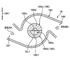
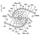
- FIG. 13 is a view of the blower 18 viewed from the same direction as FIG. 12 and shows the temperature distribution of the air suction port 185.
- both the air mix doors 22 and 24 are positioned so that the 2nd ventilation path 122 may have a larger warm air ratio than the 1st ventilation path 121, in FIG.
- the inner area 185e of the second suction range 185b is larger than the inner area 185c of the first suction range 185a.
- the cold air which is the air flowing into the outer regions 185d and 185f of the both suction ranges 185a and 185b, is located between the blades 182a of the centrifugal fan 182 and the fan axis.
- the air flows in the CLf direction with a bias toward the air suction port 185 (see FIG. 10).
- warm air which is air flowing into the inner regions 185c and 185e, flows between the blades 182a in a direction opposite to the air suction port 185 side in the direction of the fan axis CLf.
- the warm air heated by the first heating unit 161 or the second heating unit 162 and the cold air not heated are the blades 182 a of the centrifugal fan 182. It flows in every interval. Thereby, the air blown out between the rotating blades 182a is well mixed, and the temperature unevenness of the air blown out from each of the first air outlet 186 and the second air outlet 187 in the bi-level mode can be suppressed.
- the ventilation part 12 is formed with the first ventilation path 121 having the first downstream end 121b and the second ventilation path 122 having the second downstream end 122b.
- the first air outlet 186 has a second suction range 185b in which the air sucked from the first suction range 185a connected to the first downstream end 121b is connected to the second downstream end 122b. It is arranged to be blown out more than the air sucked from.
- the 2nd air blower outlet 187 is arrange
- the first nose portion 184b and the second nose portion 184d are arranged so as to overlap the virtual boundary surface FCsp, the first nose portion 184b and the second nose portion 184d are sucked from the first suction range 185a of the air suction port 185.
- the air and the air sucked from the second suction range 185b are separated with high accuracy, the air from the first suction range 185a is caused to flow to the first air outlet 186, and the air from the second suction range 185b is second air. It is possible to flow to the outlet 187.
- the first heating unit 161 is disposed adjacent to the partition part 123 in the first ventilation path 121, and the second heating unit 162 is adjacent to the partition part 123 in the second ventilation path 122. Therefore, each of the first heating unit 161 and the second heating unit 162 can be configured by the heater core 16 that is a single heating device.
- the fan case portion 184 is configured such that the air sucked from the first suction range 185 a of the air suction port 185 flows exclusively to the first air outlet 186 and the second suction of the air suction port 185. Since the air sucked from the range 185b is formed to flow exclusively to the second air outlet 187, the air blown from the first air outlet 186 and the air blown from the second air outlet 187 It is possible to blow out air to the air outlets 186 and 187 with one blower 18 while controlling the temperature independently.
- the heater core 16 of the present embodiment is different from the first to fourth embodiments in that the four sides of the heater core 16 are separated from the end portion of the ventilation path 120.
- hot air and cold air are generated in all angle ranges (that is, over the entire circumference of the fan) of the angle range expected from the fan axis CLf at the air suction port 185.
- the degree of mixing of warm air and cold air is further improved as compared with the first to fourth embodiments.
- each of the plurality of 121 and 122 has one heater core and one evaporator. Therefore, the air conditioning unit 10 can be easily configured as compared with a configuration having a plurality of heater cores or evaporators in one ventilation path.
- FIG. 14 is a cross-sectional view schematically showing the air conditioning unit 10 of the present embodiment, and corresponds to FIG. 10 of the first embodiment.
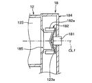
- 15 is a cross-sectional view taken along the line XV-XV in FIG.
- the first warm air duct 28 provided in the first ventilation path 121 and the second ventilation path 122.
- a second hot air duct 30 provided therein.
- the first hot air duct 28 and the second hot air duct 30 are resin members formed integrally with the partition portion 123.
- the first warm air duct 28 is formed in the first ventilation path 121 from the first heating unit 161 to the air suction port 185, and guides the air flowing out from the first heating unit 161 to the inner region 185c of the first suction range 185a. .
- the first heating unit 161 is disposed at the upstream end of the air flow of the first hot air duct 28. That is, similarly to the fifth embodiment, the first heating unit 161 is arranged such that the air flowing into the inner region 185c in the first suction range 185a is hotter than the air flowing into the outer region 185d. Yes.
- the warm air duct 28 guides the warm air flowing out from the first heating unit 161 to the inner region 185c by its inner wall surface, and detours the first heating unit 161 by its outer wall surface in a reverse view.
- the cooled air is guided to the outer region 185d.
- the second hot air duct 30 has a symmetrical shape with the partition 123 as a reference.
- the second hot air duct 30 is formed in the second ventilation path 122 from the second heating unit 162 to the air suction port 185, and the air flowing out from the second heating unit 162 is sent to the inner region 185e of the second suction range 185b. Lead.
- the second heating unit 162 is disposed at the upstream end of the air flow of the second hot air duct 30. That is, as in the fifth embodiment, the second heating unit 162 is arranged such that the air flowing into the inner region 185e in the second suction range 185b is hotter than the air flowing into the outer region 185f. Yes.
- the warm air duct 30 guides the warm air flowing out from the second heating unit 162 to the inner region 185e by its inner wall surface, and detours the second heating unit 162 by its outer wall surface in a reverse view.
- the cold air thus conducted is guided to the outer region 185f.
- the first hot air duct 28 guides the air flowing out from the first heating unit 161 to the inner region 185c of the first suction range 185a, and the second hot air duct 30
- the air that has flowed out of the heating unit 162 is guided to the inner region 185e of the second suction range 185b. Therefore, the temperature distribution of the air flowing into the air suction port 185 can be accurately formed so that the temperature unevenness in the circumferential direction around the fan shaft center CLf is suppressed and the temperature gradient is in the radial direction of the fan shaft center CLf. it can.
- the bi-level mode the temperature unevenness of the air blown out from each of the first air outlet 186 and the second air outlet 187 can be suppressed as compared with the fifth embodiment described above.
- the evaporator, the heater core, and the air mix door as a whole correspond to an example of a temperature adjusting unit that generates a temperature distribution in the air flow in the ventilation path.
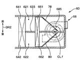
- FIG. 16 is a sectional view schematically showing the air conditioning unit 8 of the present embodiment
- FIG. 17 is a sectional view taken along the line XVII-XVII in FIG.
- the air conditioning unit 8 of the present embodiment includes two air conditioning units 58 and 60 configured in the same manner as the air conditioning unit 10 of the sixth embodiment, that is, the first air conditioning unit 58 and the first air conditioning unit 58.
- Two air conditioning units 60 are provided.
- the same reference numerals used in the first air conditioning unit 58 are the same as those in the sixth embodiment.
- the symbols used in the second air conditioning unit 60 are different from those in the sixth embodiment.
- the ventilation unit 12 is denoted by reference numeral 62
- the first ventilation path 121 is denoted by reference numeral 621
- the second ventilation path 122 is denoted by reference numeral 622
- the partition part 123 is denoted by reference numeral 623
- the evaporator 14 is denoted by reference numeral 64
- the first cooling part 141 is indicated by reference numeral 641
- the second cooling part 142 is indicated by reference numeral 642
- the heater core 16 is indicated by reference numeral 66
- the first heating part 161 is indicated by reference numeral 661
- the second heating part 162 is indicated by reference numeral 662
- the blower 18 is indicated by reference numeral 68
- an electric motor 181 is the reference numeral 681
- the centrifugal fan 182 is the reference numeral 682
- the fan case portion 184 is the reference numeral 684
- the air inlet 185 is the reference numeral 685
- the first air outlet 186 is the reference numeral 686
- the corresponding second air mix door 24, fan case part 184, and centrifugal fan 182 constitute the first air conditioning part 58.
- the second air mix door 74, the fan case unit 684, and the centrifugal fan 682 constitute the second air conditioning unit 60.
- the ventilation unit 12 of the first air conditioning unit 58 and the ventilation unit 62 of the second air conditioning unit 60 are integrally formed, and the first air conditioning unit 58 is disposed above the second air conditioning unit 60. And the 1st air-conditioning part 58 and the 2nd air-conditioning part 60 are comprised so that a symmetrical shape may be made
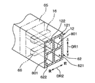
- the air conditioning unit 8 includes an upper and lower partition 801 that partitions the first ventilation path 121 and the second ventilation path 122 of the first air conditioning section 58 from the first ventilation path 621 and the second ventilation path 622 of the second air conditioning section 60. Yes.
- the vertical partition 801 has a flat plate shape whose thickness direction is the vertical direction.
- the 1st ventilation path 121 and the 2nd ventilation path 122 are arrange
- the first ventilation path 121 and the second ventilation path 122 are arranged side by side in the longitudinal direction DR2 of the vehicle.
- the first ventilation path 121 and the second ventilation path 122 are formed so as to extend in the left-right direction of the vehicle, the first ventilation path 121 is disposed on the front side, and the second ventilation path 122 is disposed on the rear side. Yes.
- This arrangement is the same for the ventilation paths 621 and 622 of the second air conditioning unit 60.
- the blower 18 is arranged so that the fan axis CLf faces the horizontal direction.
- the blower 18 of the first air-conditioning unit 58. is arranged so that the fan axis CLf faces the vertical direction DR1. This arrangement is the same for the blower 68 of the second air conditioning unit 60.
- the fan axis CLf of the blower 18 of the first air conditioning unit 58 and the fan axis CLf of the blower 68 of the second air conditioning unit 60 are arranged on a straight line.
- the first air outlet 186 of the first air conditioning unit 58 is connected to the outlet located on the upper right side of the dashboard in the passenger compartment via a duct (not shown) connected to the first air outlet 186. It is connected. That is, the first air outlet 186 is a face outlet on the driver's seat that is the right front seat.
- the 2nd air blower outlet 187 of the 1st air-conditioning part 58 is connected to the blower outlet arrange
- the 1st air blower outlet 686 of the 2nd air conditioning part 60 is connected to the blower outlet arrange
- the second air outlet 687 of the second air conditioning unit 60 is connected to an outlet arranged at the lower left side of the vehicle interior via a duct (not shown) connected to the second air outlet 687. Yes. That is, the second air outlet 687 is a foot outlet on the passenger seat side.
- the heater core 16 of the first air conditioning unit 58 is a separate device from the heater core 66 of the second air conditioning unit 60.
- the evaporator 14 of the first air conditioning unit 58 and the evaporator of the second air conditioning unit 60 are used.
- 64 constitutes a single rectangular parallelepiped cooling device 65. That is, the two cooling units 141 and 142 in the first air conditioning unit 58 and the two cooling units 641 and 642 in the second air conditioning unit 60 constitute one cooling device 65.
- the air conditioning unit 8 includes the first air conditioning unit 58 and the second air conditioning unit 60 that are configured in the same manner as the air conditioning unit 10 of the sixth embodiment.
- the air blown out from 186, 187, 686, and 687 can be independently temperature controlled. Therefore, for example, in the passenger compartment, the temperature around the upper body of the driver's side occupant, around the feet of the driver's side occupant, around the upper body of the passenger's side occupant, and around the feet of the passenger's side occupant .
- the first nose portion 184b and the second nose portion 184d are disposed so as to contact the virtual boundary surface FCsp, but the nose portions 184b and 184d intersect the virtual boundary surface FCsp. It does not matter even if it is arranged to do.
- the first heating unit 161 is configured such that the air flowing into the inner region 185c in the first suction range 185a of the air suction port 185 flows into the outer region 185d. It arrange
- the second suction range 185b For example, if the first heating unit 161 and the second heating unit 162 are arranged as independent heater cores and are separated from the partition unit 123, the air flowing into the inner regions 185c and 185e flows into the outer regions 185d and 185f. It is possible to realize a temperature distribution that is lower than the temperature of the air.
- the hot air ducts 28 and 30 guide the cold air that bypasses the heating parts 161 and 162 to the inner regions 185c and 185e by the inner wall surfaces thereof,
- the warm air that has passed through the heating units 161 and 162 is guided to the outer regions 185d and 185f by the wall surfaces.
- air flowing into the inner region 185p at the air suction port 185 is more than air flowing into the outer regions 185q and 185r. It is arranged to be hot. However, conversely, the air flowing into the inner region 185p may be disposed at a lower temperature than the air flowing into the outer regions 185q and 185r.
- the hot air duct 26 guides the cool air that bypasses the heater core 16 to the inner region 185p by its inner wall surface, and passes through the heater core 16 by its inner wall surface in a reverse view.
- the warm air is guided to the outer regions 185q and 185r.
- the fan shaft center CLf of the blower 18 of the first air conditioning unit 58 and the fan shaft center CLf of the blower 68 of the second air conditioning unit 60 are arranged in a straight line, but both fan shaft centers CLf. May be offset from each other.
- the downstream end portion 123a of the partition portion 123 is disposed at a position overlapping with the air suction port 185 in the fan shaft center CLf direction.
- the centrifugal fan 182 may extend to the inside of the plurality of blades 182a.
- the sixth and seventh embodiments even if the partition part 123 is extended as described above in the sixth and seventh embodiments, the end of the hot air ducts 28, 30, 78, 80 on the downstream side of the air flow is not extended, and the fan shaft In the direction of the center CLf, the air suction ports 185 and 685 are arranged so as to overlap with each other.
- 19 is a cross-sectional view schematically showing a modification of the air conditioning unit 10 in FIG. 10
- FIG. 20 is a cross-sectional view taken along the line XX-XX in FIG.
- the blower 18 is a sirocco fan, but is not limited to a sirocco fan, and may be a turbo fan, for example.
- FIG. 21 shows the blade 182a of the centrifugal fan 182 and its peripheral portion. That is, FIG. 21 is a detailed view of the XII portion of FIG. FIG. 21A shows a case where the blower 18 is a sirocco fan, and FIG. 21B shows a case where the blower 18 is a turbo fan.
- the turbo fan shown in FIG. 21 (b) is more in the direction of the fan axis CLf than the sirocco fan shown in FIG. 21 (a).
- the height of the blade 182a is smaller toward the outer side in the radial direction of the centrifugal fan 182, and the air flow between the blades 182a is narrowed toward the outer side in the radial direction.
- the turbo fan the cold air and the warm air flowing between the blades 182a are mixed better than the sirocco fan, and the temperature unevenness of the air blown out between the blades 182a can be suppressed.
- the air blower 18 is a turbo fan
- the fan case part 184 may not be a scroll casing.
- the air mix doors 22 and 24 are provided on the upstream side of the air flow with respect to the heater cores 16 and 66, but may be provided on the downstream side of the air flow with respect to the heater cores 16 and 66.
- the first cooling unit 141 and the second cooling unit 142 constitute the evaporator 14 which is one cooling device, but may be separately configured cooling devices.
- the first heating unit 161 and the second heating unit 162 constitute the heater core 16 which is one heating device, but may be heating devices configured separately. The same applies to the sixth and seventh embodiments.
- the partition part 123 may be removed from the fifth and sixth embodiments. Even in this case, the temperature distribution in the inner regions 185c and 185e and the outer regions 185d and 185f in the air suction port 185 is substantially the same as in the fifth and sixth embodiments, so that the temperature between adjacent fan blades 182a Wind and cold wind come together.
- the position of the heater core 16 may be shifted downward.
- the imaginary line extending straight from the fan axis CLf is made to penetrate the inside of the heater core 16 instead of the periphery.
- the warm air heated through the heater core 16 is mainly used. Occupy.
- the outer region 185t corresponding to the region where the outer region 185d and the outer region 185f of the fifth embodiment are combined is mainly occupied by cold air that bypasses the heater core 16.
- the inner region 185s includes the fan axis CLf at the inside thereof instead of the periphery thereof, and the outer region 185t does not include the fan axis CLf.
- each of the evaporators 14a and 14b is inclined so as to protrude upward in the air flow direction in the ventilation path 120 as a whole.
- Each of the heater cores 16a and 16b is also inclined so as to protrude upward in the air flow direction in the ventilation path 120 as a whole.
- the evaporator 14 and the heater core 16 of the first to third embodiments are arranged at the central portion in the vertical direction so as to protrude toward the upstream side in the air flow direction. You may change into the bent shape.
- the evaporator 14 and the heater core 16 of the first to third embodiments may be changed to a shape that is bent into a curved surface as a whole so as to protrude toward the upstream side in the air flow direction. Even in this case, at least a part of the evaporator 14 and the heater core 16 is inclined with respect to the air flow direction (longitudinal direction of the ventilation path 120) in the ventilation path 120.
Landscapes
- Physics & Mathematics (AREA)
- Thermal Sciences (AREA)
- Engineering & Computer Science (AREA)
- Mechanical Engineering (AREA)
- Air-Conditioning For Vehicles (AREA)
Applications Claiming Priority (4)
| Application Number | Priority Date | Filing Date | Title |
|---|---|---|---|
| JP2013267760 | 2013-12-25 | ||
| JP2013-267760 | 2013-12-25 | ||
| JP2014243292A JP6447067B2 (ja) | 2013-12-25 | 2014-12-01 | 車両用空調ユニット |
| JP2014-243292 | 2014-12-01 |
Publications (1)
| Publication Number | Publication Date |
|---|---|
| WO2015098098A1 true WO2015098098A1 (ja) | 2015-07-02 |
Family
ID=53477994
Family Applications (1)
| Application Number | Title | Priority Date | Filing Date |
|---|---|---|---|
| PCT/JP2014/006410 Ceased WO2015098098A1 (ja) | 2013-12-25 | 2014-12-24 | 車両用空調ユニット |
Country Status (2)
| Country | Link |
|---|---|
| JP (1) | JP6447067B2 (enExample) |
| WO (1) | WO2015098098A1 (enExample) |
Cited By (4)
| Publication number | Priority date | Publication date | Assignee | Title |
|---|---|---|---|---|
| CN105202731A (zh) * | 2015-10-22 | 2015-12-30 | 南车资阳机车有限公司 | 机车驾驶室空气分配结构 |
| CN110087919A (zh) * | 2016-12-14 | 2019-08-02 | 株式会社电装 | 空调装置 |
| EP3546256A4 (en) * | 2016-11-23 | 2019-12-25 | Denso Corporation | VEHICLE CLIMATE CONTROL DEVICE |
| CN111247012A (zh) * | 2017-10-20 | 2020-06-05 | 株式会社电装 | 车辆用空调装置 |
Families Citing this family (4)
| Publication number | Priority date | Publication date | Assignee | Title |
|---|---|---|---|---|
| JP6583378B2 (ja) * | 2016-11-07 | 2019-10-02 | 株式会社デンソー | 車両用空調ユニット |
| WO2018083940A1 (ja) * | 2016-11-07 | 2018-05-11 | 株式会社デンソー | 車両用空調ユニット |
| JP2018192859A (ja) * | 2017-05-15 | 2018-12-06 | 三菱重工サーマルシステムズ株式会社 | 車両用空調装置 |
| JP6958221B2 (ja) * | 2017-10-20 | 2021-11-02 | 株式会社デンソー | 車両用空調装置 |
Citations (5)
| Publication number | Priority date | Publication date | Assignee | Title |
|---|---|---|---|---|
| JPS5233850U (enExample) * | 1975-08-30 | 1977-03-10 | ||
| JPS587486B2 (ja) * | 1978-10-06 | 1983-02-10 | 三菱自動車工業株式会社 | 車両用空気調和装置 |
| JPS62155115A (ja) * | 1985-12-27 | 1987-07-10 | Nippon Denso Co Ltd | 車両用空気調和装置 |
| JPH1134639A (ja) * | 1997-07-15 | 1999-02-09 | Nissan Motor Co Ltd | 車両用空調装置 |
| JP2000177358A (ja) * | 1998-12-16 | 2000-06-27 | Denso Corp | 車両空調装置用送風機ユニット |
Family Cites Families (3)
| Publication number | Priority date | Publication date | Assignee | Title |
|---|---|---|---|---|
| JPS5216146U (enExample) * | 1975-07-22 | 1977-02-04 | ||
| JPS60197420A (ja) * | 1984-03-20 | 1985-10-05 | Nippon Denso Co Ltd | 自動車用空調装置 |
| JPH075824U (ja) * | 1993-06-30 | 1995-01-27 | 株式会社ゼクセル | 車両用空調装置 |
-
2014
- 2014-12-01 JP JP2014243292A patent/JP6447067B2/ja not_active Expired - Fee Related
- 2014-12-24 WO PCT/JP2014/006410 patent/WO2015098098A1/ja not_active Ceased
Patent Citations (5)
| Publication number | Priority date | Publication date | Assignee | Title |
|---|---|---|---|---|
| JPS5233850U (enExample) * | 1975-08-30 | 1977-03-10 | ||
| JPS587486B2 (ja) * | 1978-10-06 | 1983-02-10 | 三菱自動車工業株式会社 | 車両用空気調和装置 |
| JPS62155115A (ja) * | 1985-12-27 | 1987-07-10 | Nippon Denso Co Ltd | 車両用空気調和装置 |
| JPH1134639A (ja) * | 1997-07-15 | 1999-02-09 | Nissan Motor Co Ltd | 車両用空調装置 |
| JP2000177358A (ja) * | 1998-12-16 | 2000-06-27 | Denso Corp | 車両空調装置用送風機ユニット |
Cited By (6)
| Publication number | Priority date | Publication date | Assignee | Title |
|---|---|---|---|---|
| CN105202731A (zh) * | 2015-10-22 | 2015-12-30 | 南车资阳机车有限公司 | 机车驾驶室空气分配结构 |
| EP3546256A4 (en) * | 2016-11-23 | 2019-12-25 | Denso Corporation | VEHICLE CLIMATE CONTROL DEVICE |
| CN110087919A (zh) * | 2016-12-14 | 2019-08-02 | 株式会社电装 | 空调装置 |
| CN110087919B (zh) * | 2016-12-14 | 2022-06-03 | 株式会社电装 | 空调装置 |
| CN111247012A (zh) * | 2017-10-20 | 2020-06-05 | 株式会社电装 | 车辆用空调装置 |
| CN111247012B (zh) * | 2017-10-20 | 2023-01-06 | 株式会社电装 | 车辆用空调装置 |
Also Published As
| Publication number | Publication date |
|---|---|
| JP6447067B2 (ja) | 2019-01-09 |
| JP2015143090A (ja) | 2015-08-06 |
Similar Documents
| Publication | Publication Date | Title |
|---|---|---|
| JP6447067B2 (ja) | 車両用空調ユニット | |
| JP5625993B2 (ja) | 車両用空調装置 | |
| US20180298914A1 (en) | Blower | |
| US11274670B2 (en) | Blower | |
| JP6958222B2 (ja) | 車両用空調装置 | |
| JP6958221B2 (ja) | 車両用空調装置 | |
| WO2015040787A1 (ja) | 空調ユニット | |
| JP6583378B2 (ja) | 車両用空調ユニット | |
| JP6555362B2 (ja) | 送風機 | |
| CN109803843B (zh) | 车辆用空调单元 | |
| JP2019025941A (ja) | 車両用空調ユニット | |
| WO2020230563A1 (ja) | 遠心送風機 | |
| CN111065533B (zh) | 用于机动车辆的风机和相应的供暖、通风和/或空调装置 | |
| WO2014058009A1 (ja) | 車両用空調装置 | |
| JP2011121488A (ja) | 車両用空調装置 | |
| CN103847462A (zh) | 车辆的后部空调 | |
| JP6961510B2 (ja) | 車両用空調装置のための送風ユニット | |
| WO2018083940A1 (ja) | 車両用空調ユニット | |
| WO2020170754A1 (ja) | 車両用空調ユニット | |
| JP7124354B2 (ja) | 車両用空調装置 | |
| CN108778794A (zh) | 车辆用空调装置 | |
| CN113260524A (zh) | 车辆用空调单元 | |
| WO2015129216A1 (ja) | 車両用空調装置 | |
| JP5527302B2 (ja) | 送風装置 | |
| JP2019011694A (ja) | 車両用空調装置のための遠心送風機 |
Legal Events
| Date | Code | Title | Description |
|---|---|---|---|
| 121 | Ep: the epo has been informed by wipo that ep was designated in this application |
Ref document number: 14873485 Country of ref document: EP Kind code of ref document: A1 |
|
| NENP | Non-entry into the national phase |
Ref country code: DE |
|
| 122 | Ep: pct application non-entry in european phase |
Ref document number: 14873485 Country of ref document: EP Kind code of ref document: A1 |