WO2015080018A1 - 紙葉類取扱装置 - Google Patents
紙葉類取扱装置 Download PDFInfo
- Publication number
- WO2015080018A1 WO2015080018A1 PCT/JP2014/080745 JP2014080745W WO2015080018A1 WO 2015080018 A1 WO2015080018 A1 WO 2015080018A1 JP 2014080745 W JP2014080745 W JP 2014080745W WO 2015080018 A1 WO2015080018 A1 WO 2015080018A1
- Authority
- WO
- WIPO (PCT)
- Prior art keywords
- shutter
- opening
- paper sheet
- sheet handling
- handling unit
- Prior art date
Links
Images


Classifications
-
- G—PHYSICS
- G07—CHECKING-DEVICES
- G07D—HANDLING OF COINS OR VALUABLE PAPERS, e.g. TESTING, SORTING BY DENOMINATIONS, COUNTING, DISPENSING, CHANGING OR DEPOSITING
- G07D11/00—Devices accepting coins; Devices accepting, dispensing, sorting or counting valuable papers
- G07D11/10—Mechanical details
- G07D11/14—Inlet or outlet ports
Definitions
- the present invention relates to a paper sheet handling apparatus.
- the paper sheet handling device constitutes an automated cash transaction machine (Automated Teller Machine; hereinafter referred to simply as ATM) and houses various equipment units such as banknote handling units, control units, and power supplies in a housing that forms the exterior of the device. is doing.
- ATM Automated Teller Machine
- the customer service operation surface of the housing is provided with a receiving and discharging port serving as both a paper sheet receiving port and a discharging port.
- a shutter is disposed between the acceptance / release port and the concave opening for entering and exiting paper sheets provided in the banknote handling unit, and the shutter opens and closes the acceptance / discharge port and the concave opening.
- the paper sheet handling unit is stored in a predetermined storage position of the housing under the ATM operating conditions.
- the paper sheet handling unit is provided inside the housing for the convenience of maintenance work such as collection and replenishment of paper sheets. It can be pulled out from the storage, and is stored again in a predetermined storage position after maintenance work. Every time such a paper sheet handling unit is pulled out and stored, not only the positional relationship between the receiving and discharging opening of the housing and the concave opening of the banknote handling unit but also the position of the shutter must be adjusted.
- a method of attaching a shutter mechanism to a housing so as to be displaceable for example, Japanese Patent Application Laid-Open No. 2011-170655.
- the shutter mechanism has a built-in motor for driving the shutter for the purpose of opening and closing the shutter, and a cable such as a power source or a signal line is wired from the device control unit to the motor. Therefore, not only the displacement of the shutter mechanism itself mounted on the housing, but also the handling of the bill handling unit has to be made so as not to hinder the withdrawal and storage of the bill handling unit, which is complicated. In addition, since the shutter mechanism itself is mounted inside the housing and can be displaced on the inside of the housing, the shutter mechanism needs to be installed in a limited work space inside the housing. Not only installation work but also maintenance work was complicated.
- Patent Document 1 is based on the premise that the shutter mechanism is provided in the casing, the actual situation is that the configuration proposed in Patent Document 1 cannot be applied as it is.
- the form of the present invention is: A paper sheet handling device, A housing provided with a receiving and discharging port serving as a receiving port and a discharging port for paper sheets on the customer service operation surface; A paper sheet handling unit having a concave opening for entering and exiting paper sheets, and facing the concave opening to the receiving and discharging port when stored in a predetermined storage position inside the housing; A shutter mechanism that has a shutter interposed between the receiving and discharging opening facing the opening and the opening of the concave opening, and that opens and closes the receiving and discharging opening and the concave opening by driving the shutter; , The paper sheet handling unit is equipped with the shutter mechanism mounted on the side of the concave opening in a state in which the shutter for opening and closing the concave opening is displaceably supported, The housing induces displacement of the shutter relative to the receiving and discharging port by contact with
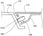
- FIG. 3 is an explanatory diagram schematically showing a configuration in which a main part is viewed in section along line 3-3 in FIG. 1;
- FIG. 4 is an explanatory diagram schematically showing a configuration in which a main part is viewed in section along line 4-4 in FIG. 3;
- FIG. 3 is an explanatory diagram schematically showing a configuration in which a main part is viewed in section along line 3-3 in FIG. 1;
- FIG. 4 is an explanatory diagram schematically showing a configuration in which a main part is viewed in section along line 4-4 in FIG. 3;
- FIG. 3 is an explanatory diagram schematically showing a configuration in
- FIG. It is explanatory drawing which shows the shutter mechanism 130 in front view in the state which open
- FIG. It is explanatory drawing which fractures
- FIG. 5 is an explanatory view schematically showing a main part of an embodiment in which the shutter mechanism 130 itself can be displaced in the opening width direction, corresponding to FIG. 4.
- FIG. 6 is an explanatory view corresponding to FIG.
- FIG. 15 is an explanatory view showing the shutter mechanism displacement portion 138 in a cross-sectional view along the line 15-15 in FIG.
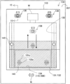
- FIG. 1 is an explanatory view schematically showing the overall appearance of an automatic teller machine 100 according to the present embodiment.
- automatic teller machine 100 is simply referred to as ATM 100.
- the ATM 100 of the present embodiment includes a casing 110 that has a box-shaped appearance of the apparatus, and the casing 110 has a vertical and horizontal dimension of about 1000 mx 500 mm.
- the ATM 100 has an upper front plate 111 extending vertically from the front upper end side of the housing 110 and an inclined front plate 112 extending inclined from the lower end thereof facing the customer, and the card slot 113 and the first customer on the upper front plate 111.
- the operation unit 114 is provided, and the inclined front plate 112 is provided with a deposit / withdrawal port 115 and a second customer operation unit 116.
- the card slot 113 is an opening for inserting a card from the customer and paying out the card to the customer, and exchanges the card with the card / detail slip processing unit 120.
- the statement slip processing unit 120 is disposed inside the casing of the upper front plate 111, reads various information of the card inserted by the customer into the card slot 113, processes the data, and prints a statement slip of the transaction performed by the customer. To the card slot 113.
- the first customer operation unit 114 performs display related to the ATM function such as a list of transaction contents desired by the customer, and outputs the customer-desired transaction contents to a main body control unit 102 described later through customer operation.
- the inclined front plate 112 is inclined at an inclination angle that is easily visible to customers who make transactions, and the second customer operation unit 116 provided on the inclined front plate 112 displays a numeric key or the like for supporting customer-desired transactions.
- a guidance display of operation details, an operation support display described later, and the like are performed, and a signal corresponding to a customer's key operation is output to the main body control unit 102.
- the deposit / withdrawal port 115 located on the right side of the second customer operation unit 116 is an opening formed in a horizontally long shape so as to serve as both a bill receiving port and a discharge port, and is normally closed by a shutter 131 and Is opened.
- the banknote handling unit 200 is housed inside a housing on the back side of the deposit / withdrawal port 115, and a shutter mechanism 130 is interposed between the deposit / withdrawal port 115 and the banknote handling unit 200.
- the shutter mechanism 130 drives the shutter 131 to open and close a deposit / withdrawal port 115 and a later-described concave opening 206 of the bill handling unit 200.
- the configuration of the shutter mechanism 130 and shutter driving will be described later.
- FIG. 2 is a block diagram showing a control configuration for controlling transaction processing of the ATM 100.
- the ATM 100 a case where processing such as depositing, paying, and transferring banknotes is shown using a card, banknote, and statement slip as a medium.
- the card / detail slip processing unit 120, the bill handling unit 200, the first customer operation unit 114, and the second customer operation unit 116 provided in the ATM 100 are connected to the main body control unit 102 through a high-speed communication line.
- the shutter mechanism 130 is mounted on the banknote handling unit 200, the banknote handling unit 200 shown in FIG. 2 includes the shutter mechanism 130.
- the ATM 100 executes a processing operation related to transaction contents according to the customer operation of the first customer operation unit 114 or the second customer operation unit 116.
- an external interface unit 103, a staff operation unit 104, and an external storage device 105 are connected to the main body control unit 102 by a bus connection or the like, and necessary data is exchanged with these units.
- the power supply unit 106 is involved in power supply to each of the above devices.
- FIG. 3 is an explanatory diagram schematically showing a configuration of the principal part taken along a line 3-3 in FIG. 1
- FIG. 4 is a schematic diagram of the structure of the principal part taken along a line 4-4 in FIG.
- FIG. 3 is an explanatory diagram schematically showing a configuration of the principal part taken along a line 3-3 in FIG. 1
- FIG. 4 is a schematic diagram of the structure of the principal part taken along a line 4-4 in FIG.
- the banknote handling unit 200 can be pulled out from the inside of the housing and stored in a predetermined storage position shown in FIG.
- the banknote handling unit 200 has a unit inclined surface 207 as a front surface at the top of the unit, and is provided with a concave opening 206 for entering and exiting paper sheets.
- the unit inclined surface 207 is inclined following the inclination of the inclined front plate 112 of the housing 110.
- the concave opening 206 is opposed to the deposit / withdrawal port 115 of the housing 110, and between the concave opening 206 and the deposit / withdrawal port 115.
- a shutter mechanism 130 is interposed.
- banknote handling unit 200 involves storage, collection, maintenance, and replenishment of banknotes, at that time, a housing rear door (not shown) can be opened and pulled out from the inside of the housing. Then, the banknote handling unit 200 is stored in the storage position in FIG. 3 and pulled out of the housing by a roller mechanism or a rail guide mechanism (not shown) at the bottom of the unit.
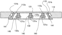
- the shutter mechanism 130 includes a shutter 131, a base plate 132, a shutter case 133, and a shutter drive motor M, and is fixedly attached to the unit inclined surface 207 of the banknote handling unit 200 via the shutter case 133.
- FIG. 5 is an explanatory view showing the shutter mechanism 130 in a front view with the shutter 131 closing the deposit / withdrawal port 115 and the concave opening 206
- FIG. 6 shows the shutter 131 opening the deposit / withdrawal port 115 and the concave opening 206. It is explanatory drawing which shows the shutter mechanism 130 in front view.
- the shutter 131 has vertical and horizontal dimensions capable of closing the opening area of the concave opening 206 and the deposit / withdrawal port 115, and opens and closes along the vertical direction of the concave opening 206 and the deposit / withdrawal port 115 as indicated by the white arrows in FIG. To drive.
- the shutter 131 is inclined such that the concave opening 206 intersecting the opening / closing driving direction and the shutter side wall in the opening width direction of the deposit / withdrawal port 115 become wider toward the concave opening 206.
- An inclined side wall 131b is formed, and a convex piece 131a is projected from the lower surface of the shutter between both side walls. As shown in FIGS.
- the base plate 132 includes support legs 132a that protrude from the upper surface of the plate.
- the support legs 132a are disposed on both sides of the convex piece 131a of the shutter 131 and hold the engagement pins 145, as shown in the respective drawings. Since the engagement pin 145 held by the support leg 132a passes through the convex piece 131a, the shutter 131 is shown in the numerical range obtained by subtracting the thickness of the convex piece 131a from the interval between the support legs 132a. As indicated by an arrow W in FIG. 8, the base plate 132 can be displaced, and this numerical range is a displacement allowable amount.
- the displacement direction of the shutter 131 is the opening width direction of the deposit / withdrawal port 115 intersecting the opening / closing drive direction
- the shutter 131 can be displaced in the opening width direction with respect to the deposit / withdrawal port 115.
- the concave opening 206 even if the shutter 131 is displaced in the opening width direction by the above-described displacement width, the shutter 131 closes all the opening areas of the concave opening 206 and the deposit / withdrawal port 115 as shown in FIG.
- the allowable displacement of the shutter 131 described above is that the shutter 131 for aligning the shutter 131 with the deposit / withdrawal port 115 when the banknote handling unit 200 is stored in the storage position inside the housing 110 as will be described later.
- the amount of displacement is set to an amount that can correct the maximum amount of positional deviation in the width direction between the shutter 131 and the housing 110. That is, the opposing width of the support leg 132a and the thickness of the convex piece 131a are defined so that an allowable displacement amount is obtained.
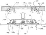
- the shutter case 133 includes a case opening 134 on the lower end side of the case and a shutter storage portion 135 on the upper end side of the case.
- the case opening 134 is opened and closed by the shutter 131 and is opened with approximately the same size as the deposit / withdrawal port 115 and the concave opening 206 facing each other with the shutter 131 interposed therebetween.
- the shutter accommodating portion 135 is a hollow recess extending from the upper end side wall of the case opening 134 and accommodates the shutter 131 together with the base plate 132.
- the shutter 131 When the shutter 131 is driven to open and is housed in the shutter housing part 135 together with the base plate 132, the shutter 131 is retracted from the case opening part 134 of the shutter case 133 as shown in FIG.
- the deposit / withdrawal port 115 and the concave opening 206 of the banknote handling unit 200 are fully opened, and the case opening 134 connects the deposit / withdrawal port 115 and the concave opening 206 to communicate with each other.
- the shutter 131 when the shutter 131 is driven to close the opening from the housed state in the shutter housing part 135, the shutter 131 has not only the case opening part 134 but also the deposit / withdrawal port 115 and the concave opening part 206 as shown in FIG. Even to close these.
- the shutter 131 is opened and closed by a shutter drive motor M that rotates forward and backward under the control of the main body control unit 102.
- the shutter drive motor M transmits the forward and reverse drive force to the base plate via a transmission mechanism (not shown). 132.
- the opening / closing operation of the shutter 131 will be described in association with bill handling.
- the base plate 132 to which this driving force has been transmitted is driven backward (opening drive) together with the shutter 131 supported by the support legs 132a and the engaging pins 145 so as to be accommodated in the shutter accommodating portion 135, and not only the case opening 134.
- the deposit / withdrawal port 115 and the concave opening 206 are fully opened.
- the main body control unit 102 drives the shutter drive motor M in the reverse direction, so that the shutter 131 is driven forward (closed drive) to the case opening 134 side together with the base plate 132 to which the driving force is transmitted.
- the case opening 134 but also the deposit / withdrawal port 115 and the concave opening 206 are closed.
- the banknote handling unit 200 receives control of the main body control unit 102, and receives the banknote (payment banknote) received in the concave opening 206 by a banknote processing mechanism (not shown) in the unit. A predetermined number of dispensed banknotes that have been received and exchanged are fed out into the concave opening 206. Even when the banknotes fed out to the concave opening 206 are paid out to the customer, the shutter 131 is driven to open and close as described above.
- the shutter 131 that opens and closes as described above is supported to be displaceable in the opening width direction of the deposit / withdrawal port 115 and the concave opening 206 with respect to the base plate 132 as described above, and the base plate 132 is driven together with the shutter 131.
- the shutter case 133 is fixed in the opening width direction. That is, the shutter mechanism 130 supports the shutter 131 so as to be displaceable in the opening width direction, and is attached to the unit inclined surface 207 of the bill handling unit 200, and the deposit / withdrawal port 115 and the concave opening 206 facing the shutter 131. Between.
- the banknote handling unit 200 When viewed from the banknote handling unit 200, the banknote handling unit 200 supports the shutter mechanism 130 on the side of the concave opening 206 in a state where the shutter 131 for opening and closing the concave opening 206 is movably supported in the opening width direction. It is attached to the inclined surface 207.
- both side walls in the opening width direction of the deposit / withdrawal port 115 opened / closed by the shutter 131 as described above are formed as the opening inclined side walls 112a inclined along the inclined side wall 131b of the shutter 131, and the opening inclined side walls are provided.
- a positioning roller 140 is provided at 112a. As shown in FIG. 4, the positioning roller 140 has a roller outer peripheral surface protruding from the opening inclined side wall 112 a toward the inclined side wall 131 b of the shutter 131. Further, as shown in FIGS. 5 to 6, the positioning roller 140 is located above the upper end of the deposit / withdrawal port 115 and faces the inclined side wall 131b in the region where the shutter 131 is accommodated in the shutter accommodating portion 135. The roller outer peripheral surface is projected.
- FIG. 5 to 6 are schematic configuration diagrams, and the positioning roller 140 is drawn to interfere with the shutter case 133, but has the following positional relationship.
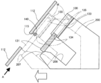
- FIG. 7 is an explanatory diagram showing a perspective view of the state of the positioning roller 140 by breaking the inclined front plate 112 at the roller mounting position
- FIG. 8 is a side view showing the state of the positioning roller 140 from the side of the roller. It is explanatory drawing shown.
- the positioning roller 140 is cantilevered by the holding bracket 142 so that it can be rotated in the forward and reverse directions (driven rotation) by the rotating shaft 144, and is fixed to the back surface of the inclined front plate 112 via the holding bracket 142.
- the holding bracket 142 is configured to have sufficient strength by side walls and ribs (not shown) for the convenience of the storage position of the banknote handling unit 200 as will be described later. Since the shutter case 133 that houses the shutter 131 is cut away so as to avoid the location of the positioning roller 140, the positioning roller 140 has its roller surface in a non-contact state with the shutter case 133. The shutter 131 is brought into contact with the inclined side wall 131b.
- the positioning rollers 140 on both sides of the deposit / withdrawal port 115 are inclined so as to define the storage position of the banknote handling unit 200 when the rollers contact the inclined side wall 131b of the shutter 131 substantially evenly. It is fixed to the face plate 112 via a holding bracket 142.
- FIG. 9 is an explanatory view illustrating the arrangement of devices and the state of driving when the banknote handling unit 200 separated from the inclined front plate 112 is returned to the storage position
- FIG. 10 is an inclined front plate. It is explanatory drawing which represents the state of apparatus arrangement
- the positioning roller 140 provided in the inclined front plate 112 around the deposit / withdrawal port 115 is not in contact with the inclined side wall 131b of the shutter 131. Therefore, the shutter 131 is free even though it is supported by the engagement pin 145 and the support leg 132a. Therefore, the shutter 131 is free from the back side of the drawing in FIG. 9 and the horizontal direction in FIG. 115 can be displaced in the opening width direction. Note that such a displaceable state is shown as a horizontal arrow W in FIGS. 5 and 6.
- FIG. 10 shows a state where only one positioning roller 140 is in contact with the inclined side wall 131b of the shutter 131. In this situation, one positioning roller 140 exerts a force in the direction indicated by the black arrow in FIG. 10 on the shutter 131 via the inclined side wall 131b by contact with the inclined side wall 131b of the shutter 131. Then, the displaceable shutter 131 receives the force in the direction of the black arrow in FIG.
- the banknote handling unit 200 is not stored due to the equal contact between the two positioning rollers 140 in the opening width direction of the deposit / withdrawal port 115 and the inclined side wall 131b of the shutter 131.
- the relative positional relationship between the deposit / withdrawal port 115 and the shutter 131 that have been collapsed is aligned so as to be uniform in the opening width direction of the deposit / withdrawal port 115. That is, the positioning roller 140 included in the housing 110 induces displacement of the shutter 131 relative to the deposit / withdrawal port 115 by contacting the inclined side wall 131b of the shutter 131 that closes the concave opening 206 of the bill handling unit 200.
- Relative alignment between the shutter 131 and the deposit / withdrawal port 115 is attempted. 9 and 10, the positioning roller 140 is shown in contact with the shutter 131 in a state where the concave opening 206 is closed. The positioning roller 140 is disposed at the upper end of the deposit / withdrawal port 115. Therefore, the shutter 131 may open the concave opening 206 when the banknote handling unit 200 is stored.
- the two positioning rollers 140 in the opening width direction of the deposit / withdrawal port 115 are in contact with the inclined side wall 131b of the shutter 131 substantially evenly. Therefore, the shutter 131 receives the guidance of the positioning roller 140 that contacts the inclined side walls 131b on both sides of the shutter during the operation period of the ATM 100, and receives the deposit / withdrawal port 115, the concave opening 206 facing the same, and the case opening therebetween. 134 is opened and closed. At this time, the positioning roller 140 rotates dependently according to the opening / closing operation of the shutter 131.
- the ATM 100 of the present embodiment having the above-described configuration includes a deposit / withdrawal port 115 serving as both a paper sheet receiving port and a discharge port on the inclined front plate 112 of the housing 110, and is stored in the storage position of the housing 110.
- a shutter mechanism 130 is mounted on a unit inclined surface 207 of the bill handling unit 200 having a concave opening 206 facing the deposit / withdrawal port 115 via a shutter case 133.
- the shutter mechanism 130 is interposed between the deposit / withdrawal port 115 and the bill handling unit 200 together with the shutter 131, and opens / closes the deposit / withdrawal port 115 and the concave opening 206 by the shutter 131.
- the ATM 100 of this embodiment supports the shutter 131 that opens and closes the concave opening 206 on the banknote handling unit 200 so that the shutter 131 can be displaced in the opening width direction of the concave opening 206 and the deposit / withdrawal port 115.
- the banknote handling unit 200 is brought close to the storage position so as to approach the inclined front plate 112 of the housing 110, the shutter 131 is temporarily displaced relative to the deposit / withdrawal port 115 in the opening width direction. Even so (see FIG.
- the shutter 131 and the deposit / withdrawal port 115 can be relatively aligned by displacing the shutter 131 in the opening width direction so that the positional deviation is corrected.
- the cables attached to the shutter mechanism 130 are not limited to the displacement of the shutter mechanism itself, and the banknote handling unit.
- the shutter 131 is supported by the shutter mechanism 130 so as to be displaceable (see FIG. 8), and the shutter mechanism 130 itself is mounted and fixed to the unit inclined surface 207 of the banknote handling unit 200. Therefore, it is only necessary to attach the shutter mechanism 130, which is simple.
- the ATM 100 of the present embodiment closes the entire area of the deposit / withdrawal port 115 and the entire area of the concave opening 206 even when the shutter 131 is displaced in the opening width direction of the deposit / withdrawal port 115. It is not necessary to adjust the position in the direction, which is simple.
- the shutter 131 has an inclined side wall 131b that is inclined so as to be wider toward the concave opening 206, and the positioning roller 140 is brought into contact with the inclined side wall 131b to open the shutter 131. A force in the width direction is applied, and the shutter 131 is displaced in the opening width direction. Therefore, according to the ATM 100 of the present embodiment, the position adjustment of the deposit / withdrawal port 115 and the shutter 131 can be made simpler by causing the shutter 131 to be displaced more reliably and smoothly.
- the ATM 100 of the present embodiment has the positioning roller 140 disposed above the upper end of the deposit / withdrawal port 115, the shutter 131 that closes the concave opening 206 of the banknote handling unit 200 is used. Even in this case, even the shutter 131 that opens the concave opening 206 is brought into contact with the inclined side wall 131b. Therefore, according to ATM100 of this embodiment, position adjustment with respect to the deposit / withdrawal port 115 and the shutter 131 can be aimed at regardless of opening and closing of the opening of the shutter 131 when the banknote handling unit 200 is stored.
- the two positioning rollers 140 in the opening width direction of the deposit / withdrawal port 115 are brought into contact with the inclined side wall 131b of the shutter 131 substantially evenly. It can be opened and closed without hindrance while being guided by positioning rollers 140 on both sides of the shutter. At this time, since the positioning roller 140 is dependently rotated according to the opening / closing operation of the shutter 131, the opening / closing driving of the shutter 131 is not hindered and smooth shutter driving can be brought about.
- FIG. 11 is an explanatory view illustrating a device configuration for adjusting the position by bringing the inclined front plate 112 spaced from the bill handling unit 200 close to the shutter mechanism 130 from the side.
- the inclined front plate 112 of this embodiment is capable of swinging around a swing fulcrum (not shown) on the upper side in FIG.
- the shutter 131 can be displaced in the opening width direction of the deposit / withdrawal port 115 as described above. Therefore, if the banknote handling unit 200 is approximately disposed at the storage position during maintenance and inspection of the banknote handling unit 200, the deposit / withdrawal port 115 and the shutter 131 can be aligned as follows.
- the banknote handling unit 200 is in the approximate storage position, in the process of swinging the inclined front plate 112 toward the shutter mechanism 130, at least one of the positioning rollers 140 is placed on the inclined side wall 131 b of the shutter 131 as described above. It contacts and displaces the shutter 131. Therefore, according to this embodiment, the effects described above can be achieved.
- FIG. 12 is an explanatory view schematically showing a main part in another embodiment corresponding to FIG.
- a positioning hemisphere 141 is provided to protrude from the opening inclined side wall 112a.
- the positioning hemisphere 141 is brought into contact with the inclined side wall 131b of the shutter 131, the displacement of the shutter 131 is induced, so that the effects described above can be obtained.
- a rod-like body having a hemispherical tip may be used instead of the positioning hemisphere 141.
- a resin material having a low coefficient of friction may be provided on the wall surface of the opening inclined side wall 112a, or resin protrusions may be provided in a scattered manner.
- FIG. 13 is an explanatory diagram schematically showing the main part of an embodiment in which the shutter mechanism 130 itself can be displaced in the opening width direction
- FIG. 14 is an embodiment in which the shutter mechanism 130 itself can be displaced in the opening width direction
- FIG. 15 is an explanatory view showing the shutter mechanism displacement portion 138 in a cross-sectional view along the line 15-15 in FIG. 14.
- the base plate 132 includes a support leg 132a having a width substantially the same as the thickness of the convex piece 131a of the shutter 131, and the convex piece 131a is formed by the support leg 132a.
- the shutter 131 is engaged with the engagement pin 145.
- the shutter 131 is integrated with the base plate 132 so as not to be displaced, and is driven to open and close together with the base plate 132 as described above.
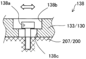
- the shutter mechanism 130 includes a shutter mechanism displacement unit 138 in the shutter case 133.
- the shutter mechanism displacement portion 138 includes a hexagon socket head bolt 138 a that is fastened and fixed to the unit inclined surface 207 of the bill handling unit 200, and an oval first length formed in the shutter case 133. It consists of a hole 138b and a second elongated hole 138c.
- the first long hole 138b is an oval having a larger diameter than the bolt head of the hexagon socket head bolt 138a
- the second long hole 138c is an oval having a slightly larger diameter than the bolt portion of the hexagon socket head bolt 138a
- the shutter mechanism 130 is mounted and fixed to the unit inclined surface 207 of the banknote handling unit 200 so as to be displaceable along the axial direction of the second long hole 138c together with the shutter case 133.
- the banknote handling unit 200 is provided with the shutter mechanism 130 itself mounted so as to be displaceable in the opening width direction of the deposit / withdrawal port 115 as described in the shutter mechanism displacement portion 138, and the shutter 131 is positioned.
- the entire shutter mechanism 130 can be displaced by contact between the roller 140 and the inclined side wall 131b. Therefore, the effects described above can also be achieved by this embodiment.
- the shutter mechanism 130 is inclined with respect to the positioning roller 140. It can be displaced more easily by contact with the side wall 131b.
- the present invention is not limited to the above-described embodiment, and can be realized with various configurations without departing from the spirit of the present invention.
- the technical features of the embodiments corresponding to the technical features in each embodiment described in the summary section of the invention are intended to solve part or all of the above-described problems, or part of the above-described effects. Or, in order to achieve the whole, it is possible to replace or combine as appropriate. Further, if the technical feature is not described as essential in the present specification, it can be deleted as appropriate.
- the present invention can also be realized in various forms other than the forms described in the claims. For example, a paper sheet handling apparatus in an ATM that handles only banknotes, and both banknotes and coins. It can be realized in the form of a paper sheet handling device in the handling ATM.
- the ATM 100 in which the banknote handling unit 200 is stored and pulled out from the rear with respect to the casing 110 has been described.
- the casing 110 is stored and pulled out forward with respect to the banknote handling unit 200 fixed in reverse. It is also applicable to the structure to be made.
- the present invention can also be applied to the ATM 100 used outdoors or indoors in an installation environment.
Landscapes
- Physics & Mathematics (AREA)
- General Physics & Mathematics (AREA)
- Pile Receivers (AREA)
- Financial Or Insurance-Related Operations Such As Payment And Settlement (AREA)
- Sheets, Magazines, And Separation Thereof (AREA)
Applications Claiming Priority (2)
| Application Number | Priority Date | Filing Date | Title |
|---|---|---|---|
| JP2013-246969 | 2013-11-29 | ||
| JP2013246969A JP6030537B2 (ja) | 2013-11-29 | 2013-11-29 | 紙葉類取扱装置 |
Publications (1)
| Publication Number | Publication Date |
|---|---|
| WO2015080018A1 true WO2015080018A1 (ja) | 2015-06-04 |
Family
ID=53198962
Family Applications (1)
| Application Number | Title | Priority Date | Filing Date |
|---|---|---|---|
| PCT/JP2014/080745 WO2015080018A1 (ja) | 2013-11-29 | 2014-11-20 | 紙葉類取扱装置 |
Country Status (3)
| Country | Link |
|---|---|
| JP (1) | JP6030537B2 (zh) |
| CN (1) | CN104680643B (zh) |
| WO (1) | WO2015080018A1 (zh) |
Families Citing this family (1)
| Publication number | Priority date | Publication date | Assignee | Title |
|---|---|---|---|---|
| JP7322587B2 (ja) * | 2019-08-16 | 2023-08-08 | 沖電気工業株式会社 | 媒体取引装置 |
Citations (4)
| Publication number | Priority date | Publication date | Assignee | Title |
|---|---|---|---|---|
| JPS6215693A (ja) * | 1985-07-15 | 1987-01-24 | 株式会社日立製作所 | シヤツタ機構 |
| JPH08329311A (ja) * | 1995-06-02 | 1996-12-13 | Hitachi Ltd | 電子機器媒体出し入れ口実装方式 |
| JP2011170655A (ja) * | 2010-02-19 | 2011-09-01 | Hitachi Omron Terminal Solutions Corp | 紙葉類取扱装置 |
| JP2013050769A (ja) * | 2011-08-30 | 2013-03-14 | Fujitsu Frontech Ltd | 自動取引装置 |
Family Cites Families (5)
| Publication number | Priority date | Publication date | Assignee | Title |
|---|---|---|---|---|
| JP4408373B2 (ja) * | 2004-01-23 | 2010-02-03 | 日立オムロンターミナルソリューションズ株式会社 | 紙幣入出金装置 |
| JP4846507B2 (ja) * | 2006-10-11 | 2011-12-28 | 日立オムロンターミナルソリューションズ株式会社 | 現金自動取引装置 |
| JP4889456B2 (ja) * | 2006-11-24 | 2012-03-07 | 日立オムロンターミナルソリューションズ株式会社 | 紙幣入出金装置および紙幣入出金装置制御方法 |
| JP5174469B2 (ja) * | 2008-01-11 | 2013-04-03 | 日立オムロンターミナルソリューションズ株式会社 | 外部シャッター機構及び現金自動取引装置 |
| JP5778073B2 (ja) * | 2012-04-18 | 2015-09-16 | 日立オムロンターミナルソリューションズ株式会社 | 紙葉類取扱装置および紙葉類取扱方法 |
-
2013
- 2013-11-29 JP JP2013246969A patent/JP6030537B2/ja active Active
-
2014
- 2014-11-13 CN CN201410640079.4A patent/CN104680643B/zh active Active
- 2014-11-20 WO PCT/JP2014/080745 patent/WO2015080018A1/ja active Application Filing
Patent Citations (4)
| Publication number | Priority date | Publication date | Assignee | Title |
|---|---|---|---|---|
| JPS6215693A (ja) * | 1985-07-15 | 1987-01-24 | 株式会社日立製作所 | シヤツタ機構 |
| JPH08329311A (ja) * | 1995-06-02 | 1996-12-13 | Hitachi Ltd | 電子機器媒体出し入れ口実装方式 |
| JP2011170655A (ja) * | 2010-02-19 | 2011-09-01 | Hitachi Omron Terminal Solutions Corp | 紙葉類取扱装置 |
| JP2013050769A (ja) * | 2011-08-30 | 2013-03-14 | Fujitsu Frontech Ltd | 自動取引装置 |
Also Published As
| Publication number | Publication date |
|---|---|
| CN104680643B (zh) | 2017-08-18 |
| JP6030537B2 (ja) | 2016-11-24 |
| CN104680643A (zh) | 2015-06-03 |
| JP2015106225A (ja) | 2015-06-08 |
Similar Documents
| Publication | Publication Date | Title |
|---|---|---|
| US11380157B2 (en) | Servicing and mounting features for gaming machine display screens and toppers | |
| KR101148387B1 (ko) | 현금 자동 거래 장치 | |
| US7494049B2 (en) | Shutter mechanism of automated-teller machine | |
| JP5974624B2 (ja) | 紙葉類搬送装置及び紙葉類取扱装置 | |
| JP5238316B2 (ja) | 駐車場管理機 | |
| JP6438642B2 (ja) | 紙葉類取扱装置 | |
| RU2603586C1 (ru) | Устройство обработки носителей и устройство транзакций с носителями | |
| JP6030537B2 (ja) | 紙葉類取扱装置 | |
| JP5377357B2 (ja) | 紙葉類取扱装置 | |
| JP5268687B2 (ja) | 自動取引装置 | |
| EP2509051B1 (en) | Media processing device | |
| KR101077195B1 (ko) | 지엽 취급 장치 | |
| CN103366441B (zh) | 自动交易装置和自动交易装置的防盗结构 | |
| JP2013204358A (ja) | 開閉装置 | |
| CN107341937B (zh) | 一种用于纸质介质传输的开合机构 | |
| JP2014191502A (ja) | 自動取引装置 | |
| JP4321513B2 (ja) | 紙幣収納装置および紙幣処理装置 | |
| CN210488638U (zh) | 一种钱箱导向板复位机构及钱箱 | |
| JP7197860B2 (ja) | 貨幣処理システム及び表示装置 | |
| JPH0877411A (ja) | 紙幣処理機における出金口構造 | |
| KR100874525B1 (ko) | 금융자동화기기의 차단판 개폐장치 | |
| JP6323164B2 (ja) | 自動取引装置 | |
| JP2017102805A (ja) | 自動取引装置 | |
| KR100526582B1 (ko) | 현금입출금기의 리싸이클박스 지지구조 | |
| JP2005046432A (ja) | 遊技媒体貸出装置 |
Legal Events
| Date | Code | Title | Description |
|---|---|---|---|
| 121 | Ep: the epo has been informed by wipo that ep was designated in this application |
Ref document number: 14866591 Country of ref document: EP Kind code of ref document: A1 |
|
| NENP | Non-entry into the national phase |
Ref country code: DE |
|
| 122 | Ep: pct application non-entry in european phase |
Ref document number: 14866591 Country of ref document: EP Kind code of ref document: A1 |