WO2015080018A1 - 紙葉類取扱装置 - Google Patents
紙葉類取扱装置 Download PDFInfo
- Publication number
- WO2015080018A1 WO2015080018A1 PCT/JP2014/080745 JP2014080745W WO2015080018A1 WO 2015080018 A1 WO2015080018 A1 WO 2015080018A1 JP 2014080745 W JP2014080745 W JP 2014080745W WO 2015080018 A1 WO2015080018 A1 WO 2015080018A1
- Authority
- WO
- WIPO (PCT)
- Prior art keywords
- shutter
- opening
- paper sheet
- sheet handling
- handling unit
- Prior art date
Links
Images


Classifications
-
- G—PHYSICS
- G07—CHECKING-DEVICES
- G07D—HANDLING OF COINS OR VALUABLE PAPERS, e.g. TESTING, SORTING BY DENOMINATIONS, COUNTING, DISPENSING, CHANGING OR DEPOSITING
- G07D11/00—Devices accepting coins; Devices accepting, dispensing, sorting or counting valuable papers
- G07D11/10—Mechanical details
- G07D11/14—Inlet or outlet ports
Definitions
- the present invention relates to a paper sheet handling apparatus.
- the paper sheet handling device constitutes an automated cash transaction machine (Automated Teller Machine; hereinafter referred to simply as ATM) and houses various equipment units such as banknote handling units, control units, and power supplies in a housing that forms the exterior of the device. is doing.
- ATM Automated Teller Machine
- the customer service operation surface of the housing is provided with a receiving and discharging port serving as both a paper sheet receiving port and a discharging port.
- a shutter is disposed between the acceptance / release port and the concave opening for entering and exiting paper sheets provided in the banknote handling unit, and the shutter opens and closes the acceptance / discharge port and the concave opening.
- the paper sheet handling unit is stored in a predetermined storage position of the housing under the ATM operating conditions.
- the paper sheet handling unit is provided inside the housing for the convenience of maintenance work such as collection and replenishment of paper sheets. It can be pulled out from the storage, and is stored again in a predetermined storage position after maintenance work. Every time such a paper sheet handling unit is pulled out and stored, not only the positional relationship between the receiving and discharging opening of the housing and the concave opening of the banknote handling unit but also the position of the shutter must be adjusted.
- a method of attaching a shutter mechanism to a housing so as to be displaceable for example, Japanese Patent Application Laid-Open No. 2011-170655.
- the shutter mechanism has a built-in motor for driving the shutter for the purpose of opening and closing the shutter, and a cable such as a power source or a signal line is wired from the device control unit to the motor. Therefore, not only the displacement of the shutter mechanism itself mounted on the housing, but also the handling of the bill handling unit has to be made so as not to hinder the withdrawal and storage of the bill handling unit, which is complicated. In addition, since the shutter mechanism itself is mounted inside the housing and can be displaced on the inside of the housing, the shutter mechanism needs to be installed in a limited work space inside the housing. Not only installation work but also maintenance work was complicated.
- Patent Document 1 is based on the premise that the shutter mechanism is provided in the casing, the actual situation is that the configuration proposed in Patent Document 1 cannot be applied as it is.
- the form of the present invention is: A paper sheet handling device, A housing provided with a receiving and discharging port serving as a receiving port and a discharging port for paper sheets on the customer service operation surface; A paper sheet handling unit having a concave opening for entering and exiting paper sheets, and facing the concave opening to the receiving and discharging port when stored in a predetermined storage position inside the housing; A shutter mechanism that has a shutter interposed between the receiving and discharging opening facing the opening and the opening of the concave opening, and that opens and closes the receiving and discharging opening and the concave opening by driving the shutter; , The paper sheet handling unit is equipped with the shutter mechanism mounted on the side of the concave opening in a state in which the shutter for opening and closing the concave opening is displaceably supported, The housing induces displacement of the shutter relative to the receiving and discharging port by contact with
- FIG. 3 is an explanatory diagram schematically showing a configuration in which a main part is viewed in section along line 3-3 in FIG. 1;
- FIG. 4 is an explanatory diagram schematically showing a configuration in which a main part is viewed in section along line 4-4 in FIG. 3;
- FIG. 3 is an explanatory diagram schematically showing a configuration in which a main part is viewed in section along line 3-3 in FIG. 1;
- FIG. 4 is an explanatory diagram schematically showing a configuration in which a main part is viewed in section along line 4-4 in FIG. 3;
- FIG. 3 is an explanatory diagram schematically showing a configuration in
- FIG. It is explanatory drawing which shows the shutter mechanism 130 in front view in the state which open
- FIG. It is explanatory drawing which fractures
- FIG. 5 is an explanatory view schematically showing a main part of an embodiment in which the shutter mechanism 130 itself can be displaced in the opening width direction, corresponding to FIG. 4.
- FIG. 6 is an explanatory view corresponding to FIG.
- FIG. 15 is an explanatory view showing the shutter mechanism displacement portion 138 in a cross-sectional view along the line 15-15 in FIG.
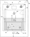
- FIG. 1 is an explanatory view schematically showing the overall appearance of an automatic teller machine 100 according to the present embodiment.
- automatic teller machine 100 is simply referred to as ATM 100.
- the ATM 100 of the present embodiment includes a casing 110 that has a box-shaped appearance of the apparatus, and the casing 110 has a vertical and horizontal dimension of about 1000 mx 500 mm.
- the ATM 100 has an upper front plate 111 extending vertically from the front upper end side of the housing 110 and an inclined front plate 112 extending inclined from the lower end thereof facing the customer, and the card slot 113 and the first customer on the upper front plate 111.
- the operation unit 114 is provided, and the inclined front plate 112 is provided with a deposit / withdrawal port 115 and a second customer operation unit 116.
- the card slot 113 is an opening for inserting a card from the customer and paying out the card to the customer, and exchanges the card with the card / detail slip processing unit 120.
- the statement slip processing unit 120 is disposed inside the casing of the upper front plate 111, reads various information of the card inserted by the customer into the card slot 113, processes the data, and prints a statement slip of the transaction performed by the customer. To the card slot 113.
- the first customer operation unit 114 performs display related to the ATM function such as a list of transaction contents desired by the customer, and outputs the customer-desired transaction contents to a main body control unit 102 described later through customer operation.
- the inclined front plate 112 is inclined at an inclination angle that is easily visible to customers who make transactions, and the second customer operation unit 116 provided on the inclined front plate 112 displays a numeric key or the like for supporting customer-desired transactions.
- a guidance display of operation details, an operation support display described later, and the like are performed, and a signal corresponding to a customer's key operation is output to the main body control unit 102.
- the deposit / withdrawal port 115 located on the right side of the second customer operation unit 116 is an opening formed in a horizontally long shape so as to serve as both a bill receiving port and a discharge port, and is normally closed by a shutter 131 and Is opened.
- the banknote handling unit 200 is housed inside a housing on the back side of the deposit / withdrawal port 115, and a shutter mechanism 130 is interposed between the deposit / withdrawal port 115 and the banknote handling unit 200.
- the shutter mechanism 130 drives the shutter 131 to open and close a deposit / withdrawal port 115 and a later-described concave opening 206 of the bill handling unit 200.
- the configuration of the shutter mechanism 130 and shutter driving will be described later.
- FIG. 2 is a block diagram showing a control configuration for controlling transaction processing of the ATM 100.
- the ATM 100 a case where processing such as depositing, paying, and transferring banknotes is shown using a card, banknote, and statement slip as a medium.
- the card / detail slip processing unit 120, the bill handling unit 200, the first customer operation unit 114, and the second customer operation unit 116 provided in the ATM 100 are connected to the main body control unit 102 through a high-speed communication line.
- the shutter mechanism 130 is mounted on the banknote handling unit 200, the banknote handling unit 200 shown in FIG. 2 includes the shutter mechanism 130.
- the ATM 100 executes a processing operation related to transaction contents according to the customer operation of the first customer operation unit 114 or the second customer operation unit 116.
- an external interface unit 103, a staff operation unit 104, and an external storage device 105 are connected to the main body control unit 102 by a bus connection or the like, and necessary data is exchanged with these units.
- the power supply unit 106 is involved in power supply to each of the above devices.
- FIG. 3 is an explanatory diagram schematically showing a configuration of the principal part taken along a line 3-3 in FIG. 1
- FIG. 4 is a schematic diagram of the structure of the principal part taken along a line 4-4 in FIG.
- FIG. 3 is an explanatory diagram schematically showing a configuration of the principal part taken along a line 3-3 in FIG. 1
- FIG. 4 is a schematic diagram of the structure of the principal part taken along a line 4-4 in FIG.
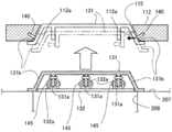
- the banknote handling unit 200 can be pulled out from the inside of the housing and stored in a predetermined storage position shown in FIG.
- the banknote handling unit 200 has a unit inclined surface 207 as a front surface at the top of the unit, and is provided with a concave opening 206 for entering and exiting paper sheets.
- the unit inclined surface 207 is inclined following the inclination of the inclined front plate 112 of the housing 110.
- the concave opening 206 is opposed to the deposit / withdrawal port 115 of the housing 110, and between the concave opening 206 and the deposit / withdrawal port 115.
- a shutter mechanism 130 is interposed.
- banknote handling unit 200 involves storage, collection, maintenance, and replenishment of banknotes, at that time, a housing rear door (not shown) can be opened and pulled out from the inside of the housing. Then, the banknote handling unit 200 is stored in the storage position in FIG. 3 and pulled out of the housing by a roller mechanism or a rail guide mechanism (not shown) at the bottom of the unit.
- the shutter mechanism 130 includes a shutter 131, a base plate 132, a shutter case 133, and a shutter drive motor M, and is fixedly attached to the unit inclined surface 207 of the banknote handling unit 200 via the shutter case 133.
- FIG. 5 is an explanatory view showing the shutter mechanism 130 in a front view with the shutter 131 closing the deposit / withdrawal port 115 and the concave opening 206
- FIG. 6 shows the shutter 131 opening the deposit / withdrawal port 115 and the concave opening 206. It is explanatory drawing which shows the shutter mechanism 130 in front view.
- the shutter 131 has vertical and horizontal dimensions capable of closing the opening area of the concave opening 206 and the deposit / withdrawal port 115, and opens and closes along the vertical direction of the concave opening 206 and the deposit / withdrawal port 115 as indicated by the white arrows in FIG. To drive.
- the shutter 131 is inclined such that the concave opening 206 intersecting the opening / closing driving direction and the shutter side wall in the opening width direction of the deposit / withdrawal port 115 become wider toward the concave opening 206.
- An inclined side wall 131b is formed, and a convex piece 131a is projected from the lower surface of the shutter between both side walls. As shown in FIGS.
- the base plate 132 includes support legs 132a that protrude from the upper surface of the plate.
- the support legs 132a are disposed on both sides of the convex piece 131a of the shutter 131 and hold the engagement pins 145, as shown in the respective drawings. Since the engagement pin 145 held by the support leg 132a passes through the convex piece 131a, the shutter 131 is shown in the numerical range obtained by subtracting the thickness of the convex piece 131a from the interval between the support legs 132a. As indicated by an arrow W in FIG. 8, the base plate 132 can be displaced, and this numerical range is a displacement allowable amount.
- the displacement direction of the shutter 131 is the opening width direction of the deposit / withdrawal port 115 intersecting the opening / closing drive direction
- the shutter 131 can be displaced in the opening width direction with respect to the deposit / withdrawal port 115.
- the concave opening 206 even if the shutter 131 is displaced in the opening width direction by the above-described displacement width, the shutter 131 closes all the opening areas of the concave opening 206 and the deposit / withdrawal port 115 as shown in FIG.
- the allowable displacement of the shutter 131 described above is that the shutter 131 for aligning the shutter 131 with the deposit / withdrawal port 115 when the banknote handling unit 200 is stored in the storage position inside the housing 110 as will be described later.
- the amount of displacement is set to an amount that can correct the maximum amount of positional deviation in the width direction between the shutter 131 and the housing 110. That is, the opposing width of the support leg 132a and the thickness of the convex piece 131a are defined so that an allowable displacement amount is obtained.
- the shutter case 133 includes a case opening 134 on the lower end side of the case and a shutter storage portion 135 on the upper end side of the case.
- the case opening 134 is opened and closed by the shutter 131 and is opened with approximately the same size as the deposit / withdrawal port 115 and the concave opening 206 facing each other with the shutter 131 interposed therebetween.
- the shutter accommodating portion 135 is a hollow recess extending from the upper end side wall of the case opening 134 and accommodates the shutter 131 together with the base plate 132.
- the shutter 131 When the shutter 131 is driven to open and is housed in the shutter housing part 135 together with the base plate 132, the shutter 131 is retracted from the case opening part 134 of the shutter case 133 as shown in FIG.
- the deposit / withdrawal port 115 and the concave opening 206 of the banknote handling unit 200 are fully opened, and the case opening 134 connects the deposit / withdrawal port 115 and the concave opening 206 to communicate with each other.
- the shutter 131 when the shutter 131 is driven to close the opening from the housed state in the shutter housing part 135, the shutter 131 has not only the case opening part 134 but also the deposit / withdrawal port 115 and the concave opening part 206 as shown in FIG. Even to close these.
- the shutter 131 is opened and closed by a shutter drive motor M that rotates forward and backward under the control of the main body control unit 102.
- the shutter drive motor M transmits the forward and reverse drive force to the base plate via a transmission mechanism (not shown). 132.
- the opening / closing operation of the shutter 131 will be described in association with bill handling.
- the base plate 132 to which this driving force has been transmitted is driven backward (opening drive) together with the shutter 131 supported by the support legs 132a and the engaging pins 145 so as to be accommodated in the shutter accommodating portion 135, and not only the case opening 134.
- the deposit / withdrawal port 115 and the concave opening 206 are fully opened.
- the main body control unit 102 drives the shutter drive motor M in the reverse direction, so that the shutter 131 is driven forward (closed drive) to the case opening 134 side together with the base plate 132 to which the driving force is transmitted.
- the case opening 134 but also the deposit / withdrawal port 115 and the concave opening 206 are closed.
- the banknote handling unit 200 receives control of the main body control unit 102, and receives the banknote (payment banknote) received in the concave opening 206 by a banknote processing mechanism (not shown) in the unit. A predetermined number of dispensed banknotes that have been received and exchanged are fed out into the concave opening 206. Even when the banknotes fed out to the concave opening 206 are paid out to the customer, the shutter 131 is driven to open and close as described above.
- the shutter 131 that opens and closes as described above is supported to be displaceable in the opening width direction of the deposit / withdrawal port 115 and the concave opening 206 with respect to the base plate 132 as described above, and the base plate 132 is driven together with the shutter 131.
- the shutter case 133 is fixed in the opening width direction. That is, the shutter mechanism 130 supports the shutter 131 so as to be displaceable in the opening width direction, and is attached to the unit inclined surface 207 of the bill handling unit 200, and the deposit / withdrawal port 115 and the concave opening 206 facing the shutter 131. Between.
- the banknote handling unit 200 When viewed from the banknote handling unit 200, the banknote handling unit 200 supports the shutter mechanism 130 on the side of the concave opening 206 in a state where the shutter 131 for opening and closing the concave opening 206 is movably supported in the opening width direction. It is attached to the inclined surface 207.
- both side walls in the opening width direction of the deposit / withdrawal port 115 opened / closed by the shutter 131 as described above are formed as the opening inclined side walls 112a inclined along the inclined side wall 131b of the shutter 131, and the opening inclined side walls are provided.
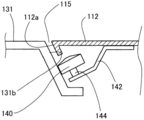
- a positioning roller 140 is provided at 112a. As shown in FIG. 4, the positioning roller 140 has a roller outer peripheral surface protruding from the opening inclined side wall 112 a toward the inclined side wall 131 b of the shutter 131. Further, as shown in FIGS. 5 to 6, the positioning roller 140 is located above the upper end of the deposit / withdrawal port 115 and faces the inclined side wall 131b in the region where the shutter 131 is accommodated in the shutter accommodating portion 135. The roller outer peripheral surface is projected.
- FIG. 5 to 6 are schematic configuration diagrams, and the positioning roller 140 is drawn to interfere with the shutter case 133, but has the following positional relationship.
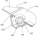
- FIG. 7 is an explanatory diagram showing a perspective view of the state of the positioning roller 140 by breaking the inclined front plate 112 at the roller mounting position
- FIG. 8 is a side view showing the state of the positioning roller 140 from the side of the roller. It is explanatory drawing shown.
- the positioning roller 140 is cantilevered by the holding bracket 142 so that it can be rotated in the forward and reverse directions (driven rotation) by the rotating shaft 144, and is fixed to the back surface of the inclined front plate 112 via the holding bracket 142.
- the holding bracket 142 is configured to have sufficient strength by side walls and ribs (not shown) for the convenience of the storage position of the banknote handling unit 200 as will be described later. Since the shutter case 133 that houses the shutter 131 is cut away so as to avoid the location of the positioning roller 140, the positioning roller 140 has its roller surface in a non-contact state with the shutter case 133. The shutter 131 is brought into contact with the inclined side wall 131b.
- the positioning rollers 140 on both sides of the deposit / withdrawal port 115 are inclined so as to define the storage position of the banknote handling unit 200 when the rollers contact the inclined side wall 131b of the shutter 131 substantially evenly. It is fixed to the face plate 112 via a holding bracket 142.
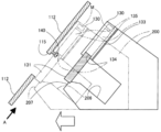
- FIG. 9 is an explanatory view illustrating the arrangement of devices and the state of driving when the banknote handling unit 200 separated from the inclined front plate 112 is returned to the storage position
- FIG. 10 is an inclined front plate. It is explanatory drawing which represents the state of apparatus arrangement
- the positioning roller 140 provided in the inclined front plate 112 around the deposit / withdrawal port 115 is not in contact with the inclined side wall 131b of the shutter 131. Therefore, the shutter 131 is free even though it is supported by the engagement pin 145 and the support leg 132a. Therefore, the shutter 131 is free from the back side of the drawing in FIG. 9 and the horizontal direction in FIG. 115 can be displaced in the opening width direction. Note that such a displaceable state is shown as a horizontal arrow W in FIGS. 5 and 6.
- FIG. 10 shows a state where only one positioning roller 140 is in contact with the inclined side wall 131b of the shutter 131. In this situation, one positioning roller 140 exerts a force in the direction indicated by the black arrow in FIG. 10 on the shutter 131 via the inclined side wall 131b by contact with the inclined side wall 131b of the shutter 131. Then, the displaceable shutter 131 receives the force in the direction of the black arrow in FIG.
- the banknote handling unit 200 is not stored due to the equal contact between the two positioning rollers 140 in the opening width direction of the deposit / withdrawal port 115 and the inclined side wall 131b of the shutter 131.
- the relative positional relationship between the deposit / withdrawal port 115 and the shutter 131 that have been collapsed is aligned so as to be uniform in the opening width direction of the deposit / withdrawal port 115. That is, the positioning roller 140 included in the housing 110 induces displacement of the shutter 131 relative to the deposit / withdrawal port 115 by contacting the inclined side wall 131b of the shutter 131 that closes the concave opening 206 of the bill handling unit 200.
- Relative alignment between the shutter 131 and the deposit / withdrawal port 115 is attempted. 9 and 10, the positioning roller 140 is shown in contact with the shutter 131 in a state where the concave opening 206 is closed. The positioning roller 140 is disposed at the upper end of the deposit / withdrawal port 115. Therefore, the shutter 131 may open the concave opening 206 when the banknote handling unit 200 is stored.
- the two positioning rollers 140 in the opening width direction of the deposit / withdrawal port 115 are in contact with the inclined side wall 131b of the shutter 131 substantially evenly. Therefore, the shutter 131 receives the guidance of the positioning roller 140 that contacts the inclined side walls 131b on both sides of the shutter during the operation period of the ATM 100, and receives the deposit / withdrawal port 115, the concave opening 206 facing the same, and the case opening therebetween. 134 is opened and closed. At this time, the positioning roller 140 rotates dependently according to the opening / closing operation of the shutter 131.
- the ATM 100 of the present embodiment having the above-described configuration includes a deposit / withdrawal port 115 serving as both a paper sheet receiving port and a discharge port on the inclined front plate 112 of the housing 110, and is stored in the storage position of the housing 110.
- a shutter mechanism 130 is mounted on a unit inclined surface 207 of the bill handling unit 200 having a concave opening 206 facing the deposit / withdrawal port 115 via a shutter case 133.
- the shutter mechanism 130 is interposed between the deposit / withdrawal port 115 and the bill handling unit 200 together with the shutter 131, and opens / closes the deposit / withdrawal port 115 and the concave opening 206 by the shutter 131.
- the ATM 100 of this embodiment supports the shutter 131 that opens and closes the concave opening 206 on the banknote handling unit 200 so that the shutter 131 can be displaced in the opening width direction of the concave opening 206 and the deposit / withdrawal port 115.
- the banknote handling unit 200 is brought close to the storage position so as to approach the inclined front plate 112 of the housing 110, the shutter 131 is temporarily displaced relative to the deposit / withdrawal port 115 in the opening width direction. Even so (see FIG.
- the shutter 131 and the deposit / withdrawal port 115 can be relatively aligned by displacing the shutter 131 in the opening width direction so that the positional deviation is corrected.
- the cables attached to the shutter mechanism 130 are not limited to the displacement of the shutter mechanism itself, and the banknote handling unit.
- the shutter 131 is supported by the shutter mechanism 130 so as to be displaceable (see FIG. 8), and the shutter mechanism 130 itself is mounted and fixed to the unit inclined surface 207 of the banknote handling unit 200. Therefore, it is only necessary to attach the shutter mechanism 130, which is simple.
- the ATM 100 of the present embodiment closes the entire area of the deposit / withdrawal port 115 and the entire area of the concave opening 206 even when the shutter 131 is displaced in the opening width direction of the deposit / withdrawal port 115. It is not necessary to adjust the position in the direction, which is simple.
- the shutter 131 has an inclined side wall 131b that is inclined so as to be wider toward the concave opening 206, and the positioning roller 140 is brought into contact with the inclined side wall 131b to open the shutter 131. A force in the width direction is applied, and the shutter 131 is displaced in the opening width direction. Therefore, according to the ATM 100 of the present embodiment, the position adjustment of the deposit / withdrawal port 115 and the shutter 131 can be made simpler by causing the shutter 131 to be displaced more reliably and smoothly.
- the ATM 100 of the present embodiment has the positioning roller 140 disposed above the upper end of the deposit / withdrawal port 115, the shutter 131 that closes the concave opening 206 of the banknote handling unit 200 is used. Even in this case, even the shutter 131 that opens the concave opening 206 is brought into contact with the inclined side wall 131b. Therefore, according to ATM100 of this embodiment, position adjustment with respect to the deposit / withdrawal port 115 and the shutter 131 can be aimed at regardless of opening and closing of the opening of the shutter 131 when the banknote handling unit 200 is stored.
- the two positioning rollers 140 in the opening width direction of the deposit / withdrawal port 115 are brought into contact with the inclined side wall 131b of the shutter 131 substantially evenly. It can be opened and closed without hindrance while being guided by positioning rollers 140 on both sides of the shutter. At this time, since the positioning roller 140 is dependently rotated according to the opening / closing operation of the shutter 131, the opening / closing driving of the shutter 131 is not hindered and smooth shutter driving can be brought about.
- FIG. 11 is an explanatory view illustrating a device configuration for adjusting the position by bringing the inclined front plate 112 spaced from the bill handling unit 200 close to the shutter mechanism 130 from the side.
- the inclined front plate 112 of this embodiment is capable of swinging around a swing fulcrum (not shown) on the upper side in FIG.
- the shutter 131 can be displaced in the opening width direction of the deposit / withdrawal port 115 as described above. Therefore, if the banknote handling unit 200 is approximately disposed at the storage position during maintenance and inspection of the banknote handling unit 200, the deposit / withdrawal port 115 and the shutter 131 can be aligned as follows.
- the banknote handling unit 200 is in the approximate storage position, in the process of swinging the inclined front plate 112 toward the shutter mechanism 130, at least one of the positioning rollers 140 is placed on the inclined side wall 131 b of the shutter 131 as described above. It contacts and displaces the shutter 131. Therefore, according to this embodiment, the effects described above can be achieved.
- FIG. 12 is an explanatory view schematically showing a main part in another embodiment corresponding to FIG.
- a positioning hemisphere 141 is provided to protrude from the opening inclined side wall 112a.
- the positioning hemisphere 141 is brought into contact with the inclined side wall 131b of the shutter 131, the displacement of the shutter 131 is induced, so that the effects described above can be obtained.
- a rod-like body having a hemispherical tip may be used instead of the positioning hemisphere 141.
- a resin material having a low coefficient of friction may be provided on the wall surface of the opening inclined side wall 112a, or resin protrusions may be provided in a scattered manner.
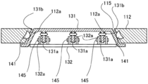
- FIG. 13 is an explanatory diagram schematically showing the main part of an embodiment in which the shutter mechanism 130 itself can be displaced in the opening width direction
- FIG. 14 is an embodiment in which the shutter mechanism 130 itself can be displaced in the opening width direction
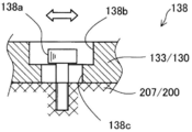
- FIG. 15 is an explanatory view showing the shutter mechanism displacement portion 138 in a cross-sectional view along the line 15-15 in FIG. 14.
- the base plate 132 includes a support leg 132a having a width substantially the same as the thickness of the convex piece 131a of the shutter 131, and the convex piece 131a is formed by the support leg 132a.
- the shutter 131 is engaged with the engagement pin 145.
- the shutter 131 is integrated with the base plate 132 so as not to be displaced, and is driven to open and close together with the base plate 132 as described above.
- the shutter mechanism 130 includes a shutter mechanism displacement unit 138 in the shutter case 133.
- the shutter mechanism displacement portion 138 includes a hexagon socket head bolt 138 a that is fastened and fixed to the unit inclined surface 207 of the bill handling unit 200, and an oval first length formed in the shutter case 133. It consists of a hole 138b and a second elongated hole 138c.
- the first long hole 138b is an oval having a larger diameter than the bolt head of the hexagon socket head bolt 138a
- the second long hole 138c is an oval having a slightly larger diameter than the bolt portion of the hexagon socket head bolt 138a
- the shutter mechanism 130 is mounted and fixed to the unit inclined surface 207 of the banknote handling unit 200 so as to be displaceable along the axial direction of the second long hole 138c together with the shutter case 133.
- the banknote handling unit 200 is provided with the shutter mechanism 130 itself mounted so as to be displaceable in the opening width direction of the deposit / withdrawal port 115 as described in the shutter mechanism displacement portion 138, and the shutter 131 is positioned.
- the entire shutter mechanism 130 can be displaced by contact between the roller 140 and the inclined side wall 131b. Therefore, the effects described above can also be achieved by this embodiment.
- the shutter mechanism 130 is inclined with respect to the positioning roller 140. It can be displaced more easily by contact with the side wall 131b.
- the present invention is not limited to the above-described embodiment, and can be realized with various configurations without departing from the spirit of the present invention.
- the technical features of the embodiments corresponding to the technical features in each embodiment described in the summary section of the invention are intended to solve part or all of the above-described problems, or part of the above-described effects. Or, in order to achieve the whole, it is possible to replace or combine as appropriate. Further, if the technical feature is not described as essential in the present specification, it can be deleted as appropriate.
- the present invention can also be realized in various forms other than the forms described in the claims. For example, a paper sheet handling apparatus in an ATM that handles only banknotes, and both banknotes and coins. It can be realized in the form of a paper sheet handling device in the handling ATM.
- the ATM 100 in which the banknote handling unit 200 is stored and pulled out from the rear with respect to the casing 110 has been described.
- the casing 110 is stored and pulled out forward with respect to the banknote handling unit 200 fixed in reverse. It is also applicable to the structure to be made.
- the present invention can also be applied to the ATM 100 used outdoors or indoors in an installation environment.
Landscapes
- Physics & Mathematics (AREA)
- General Physics & Mathematics (AREA)
- Pile Receivers (AREA)
- Financial Or Insurance-Related Operations Such As Payment And Settlement (AREA)
- Sheets, Magazines, And Separation Thereof (AREA)
Abstract
シャッタ機構(130)を紙幣取扱ユニット(200)に装着した上でシャッタ(131)に関する調整作業の簡便化を図る。ATM(100)は、筐体(110)の傾斜正面板(112)に入出金口(115)を備え、筐体(110)の収納位置に収納されると入出金口(115)に凹状開口部(206)を対向させる紙幣取扱ユニット(200)のユニット傾斜面(207)に、シャッタ機構(130)を装着して備える。シャッタ機構(130)は、入出金口(115)と紙幣取扱ユニット(200)との間にシャッタ(131)と共に介在し、シャッタ(131)により入出金口(115)と凹状開口部(206)を開閉する。ATM(100)は、紙幣取扱ユニット(200)に、シャッタ(131)を凹状開口部(206)および入出金口(115)の開口幅方向に変位可能に支持し、筐体(110)には、シャッタ(131)の傾斜側壁(131b)に接触すると、入出金口(115)に対するシャッタ(131)の開口幅方向の変位を誘起する位置決めローラー(140)を備える。
Description
本出願は、2013年11月29日に出願された日本特許出願第2013-246969号の優先権を主張し、その内容を参照することにより本出願に取り込む。
本発明は、紙葉類取扱装置に関する。
紙葉類取扱装置は、現金自動取引装置(Automated Teller Machine; 以下、単にATMとも称する)を構成し、装置外観をなす筐体に、紙幣取扱ユニットや制御部、電源等の各種機器ユニットを収納している。こうしたATMでは、顧客との間での紙幣や硬貨と云った紙葉類の取引を行うに当たり、筐体の接客操作面に紙葉類の受入口と放出口を兼ねる受入放出口を備え、この受入放出口と、紙幣取扱ユニットが備える紙葉類出入り用の凹状開口部との間にシャッタを配設し、このシャッタにて受入放出口と凹状開口部を開閉している。
紙葉類取扱ユニットは、ATMの運用状況下では、筐体の所定の収納位置に収納されているが、例えば紙葉類の回収や補充と云った保守作業を伴う都合上、筐体の内部から引出可能とされ、保守作業後に、再度、所定の収納位置に収納される。こうした紙葉類取扱ユニットの引出・収納の度に、筐体の受入放出口と紙幣取扱ユニットの凹状開口部との位置関係の調整のみならず、シャッタの位置調整も必要であった。こうした事態への対処として、シャッタ機構を、筐体に対して変位可能に取り付ける手法が提案されている(例えば、特許文献1:特開2011-170655号公報)。
シャッタ機構は、シャッタを開閉駆動する都合上、シャッタ駆動のためのモーターを内蔵し、このモーターには装置制御部から電源或いは信号線等のケーブル類が配線されている。よって、筐体に装着したシャッタ機構自体の変位については勿論のこと、紙幣取扱ユニットの引出・収納に支障が起きないよう、取り回しする必要があり、煩雑であった。加えて、シャッタ機構自体が筐体の内部に装着されて、筐体内部の側において変位可能な構成となるので、筐体内部という限られた作業スペースにおいて、シャッタ機構の取付が必要となり、その取付作業ばかりか保守作業も繁雑であった。ところで、ケーブル類の取り回しやシャッタ機構の取付・保守作業の簡便化は、シャッタ機構を紙幣取扱ユニットに装着することで解決できるものの、紙葉類取扱ユニットの引出・収納の度の筐体の受入放出口とシャッタとの位置調整は、依然として必要であり、シャッタ機構を紙幣取扱ユニットに装着した上でシャッタに関する調整作業の簡便化が要請されるに到った。なお、特許文献1は、シャッタ機構を筐体に設けることを前提とするので、特許文献1で提案された構成をそのまま適用できないのが実情である。
本発明は、上述の課題の少なくとも一部を解決するためになされたものであり、次の形態として実現することが可能である。本発明の形態は、
紙葉類取扱装置であって、
紙葉類の受入口と放出口を兼ねる受入放出口を接客操作面に備えた筐体と、
紙葉類出入り用の凹状開口部を有し、前記筐体の内部の所定の収納位置に収納されると前記受入放出口に前記凹状開口部を対向させる紙葉類取扱ユニットと、
前記対向した前記受入放出口と前記凹状開口部の開口との間にシャッタを介在させて有し、該シャッタを駆動して前記受入放出口と前記凹状開口部とを開閉するシャッタ機構とを備え、
前記紙葉類取扱ユニットは、前記凹状開口部を開閉する前記シャッタを変位可能に支持した状態で、前記シャッタ機構を前記凹状開口部の側に装着して備え、
前記筐体は、前記収納位置に収納される前記紙葉類取扱ユニットの前記凹状開口部を閉鎖する前記シャッタとの接触により、前記受入放出口に対する前記シャッタの変位を誘起して、前記シャッタと前記受入放出口との相対的な位置合わせを図るシャッタ変位誘起部を備える。
上記形態の紙葉類取扱装置によれば、シャッタ機構を紙幣取扱ユニットに装着した上でシャッタに関する調整作業の簡便化を図ることができる。
上記した以外の課題、並びにこれを解決する構成および効果は、以下の実施形態の説明により明らかにされる。
上記した以外の課題、並びにこれを解決する構成および効果は、以下の実施形態の説明により明らかにされる。
以下、本発明の実施の形態について、図面に基づき説明する。図1は本実施形態の現金自動取引装置100の全体的な外観を概略的に示す説明図である。なお、以下、現金自動取引装置100を単にATM100と称する。
本実施形態のATM100は、箱形状の装置外観をなす筐体110を備え、この筐体110は、縦横寸法が1000mx500mm程度とされている。ATM100は、筐体110の前面上端側から垂直に延びる上部正面板111と、その下端から傾斜して延びる傾斜正面板112とを顧客に対面させ、上部正面板111にカードスロット113と第1顧客操作部114とを備え、傾斜正面板112に入出金口115と第2顧客操作部116とを備える。カードスロット113は、顧客からのカードの挿入と顧客へのカード払出のための開口であり、カード・明細票処理ユニット120との間でカードの受け渡しを行う。明細票処理ユニット120は、上部正面板111の筐体内部に配設され、顧客がカードスロット113に挿入したカードの各種情報を読み取ってデータ処理し、顧客が行った取引の明細票を印字してカードスロット113に放出する。第1顧客操作部114は、顧客が所望する取引内容一覧と云ったATM機能に関する表示を行うと共に、顧客所望の取引内容を顧客操作を経て後述の本体制御部102に出力する。
傾斜正面板112は、取引する顧客が視認し易い傾斜角度で傾斜し、この傾斜正面板112に設けられた第2顧客操作部116は、顧客所望の取引を支援するための数字キー等の表示や、操作内容の案内表示、後述の操作支援表示等を行うと共に、顧客のキー操作に応じた信号を本体制御部102に出力する。第2顧客操作部116の右方に位置する入出金口115は、紙幣の受入口と放出口を兼ねるよう横長に形成された開口であり、通常は、シャッタ131により閉鎖されており、取引時において開口される。ATM100は、この入出金口115の奥側である筐体内部に紙幣取扱ユニット200を収納し、入出金口115と紙幣取扱ユニット200との間に、シャッタ機構130を介在させている。シャッタ機構130は、シャッタ131を駆動して、入出金口115と紙幣取扱ユニット200が有する後述の凹状開口部206とを開閉する。シャッタ機構130の構成とシャッタ駆動については後述する。
図2はATM100の取引処理を制御する制御構成を示すブロック図である。ここではATM100の一例として、カード、紙幣、明細票を媒体とし、紙幣の預け入れ、支払い、振り込みなどの処理を行う場合を示している。そして、このATM100に備えられている前述したカード・明細票処理ユニット120、紙幣取扱ユニット200、第1顧客操作部114および第2顧客操作部116は、それぞれ高速通信回線によって本体制御部102に接続されている。本実施形態では、シャッタ機構130を紙幣取扱ユニット200に装着したので、図2に示す紙幣取扱ユニット200には、シャッタ機構130が含まれていることになる。ATM100は、この本体制御部102の制御下で、第1顧客操作部114や第2顧客操作部116の顧客操作に応じた取引内容に関する処理動作を実行する。この他、本体制御部102には、外部インタフェース部103、係員操作部104、外部記憶装置105がバス接続等により接続されており、これらに対して必要なデータのやりとりを行なう。電源部106は、上記の各機器への電力供給に関与する。
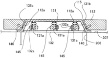
次に、シャッタ機構130を含む紙幣取扱ユニット200と傾斜正面板112の入出金口115との関係について詳述する。図3は図1における3-3線に沿って要部を断面視した構成を概略的に示す説明図、図4は図3における4-4線に沿って要部を断面視した構成を概略的に示す説明図である。
紙幣取扱ユニット200は、図1において、筐体内部から外部に引出可能とされ、図3に示す所定の収納位置に収納される。紙幣取扱ユニット200は、そのユニット上部の前面をユニット傾斜面207とし、このユニット傾斜面207に紙葉類出入り用の凹状開口部206を開口して備える。ユニット傾斜面207は、筐体110の傾斜正面板112の傾斜に倣って傾斜している。紙幣取扱ユニット200は、図3に示す収納位置に収納された状況において、凹状開口部206を筐体110の入出金口115に対向させ、この凹状開口部206と入出金口115との間にシャッタ機構130を介在させる。紙幣取扱ユニット200は、紙幣の収納、回収、保守点検、補充等を伴うため、その際には、図示しない筐体後扉を開けて、筐体内部から外部に引出可能とされる。そして、図3の収納位置への紙幣取扱ユニット200の収納および筐体外部への引出は、ユニット底部の図示しないローラー機構やレール案内機構等により支援してなされる。
シャッタ機構130は、シャッタ131と、ベースプレート132と、シャッタケース133と、シャッタ駆動モーターMとを備え、シャッタケース133を介して、紙幣取扱ユニット200のユニット傾斜面207に固定装着されている。図5はシャッタ131により入出金口115と凹状開口部206を閉鎖した状態でシャッタ機構130を正面視して示す説明図、図6はシャッタ131により入出金口115と凹状開口部206を開放した状態でシャッタ機構130を正面視して示す説明図である。
シャッタ131は、凹状開口部206および入出金口115の開口領域を塞ぎ得る縦横寸法とされ、図3の白抜き矢印のように、凹状開口部206および入出金口115の上下方向に沿って開閉駆動する。このシャッタ131は、図4に示すように、開閉駆動方向と交差する凹状開口部206および入出金口115の開口幅方向のシャッタ側壁を、凹状開口部206の側ほど幅広となるように傾斜した傾斜側壁131bとし、両側壁の間にシャッタ下面から凸状片131aを突出させている。ベースプレート132は、図4~図6に示すように、プレート上面に対向する支持脚132aを突出して備える。この支持脚132aは、上記各図に示すように、シャッタ131の凸状片131aの両側に配設され、係合ピン145を保持する。支持脚132aで保持された係合ピン145は、凸状片131aを貫通していることから、シャッタ131は、支持脚132aの対向間隔から凸状片131aの厚みを差し引いた数値範囲において、図における矢印Wに示すように、ベースプレート132に対して変位可能となり、この数値範囲が変位許容量となる。シャッタ131の変位方向は、開閉駆動方向と交差する入出金口115の開口幅方向であることから、シャッタ131は、入出金口115に対して、その開口幅方向に変位可能となる。凹状開口部206に対しても同様である。この場合、上記した変位幅でシャッタ131が開口幅方向に変位したとしても、図5に示すように、シャッタ131は、凹状開口部206および入出金口115の開口領域を総て閉鎖する。上記したシャッタ131の変位許容量は、後述するように紙幣取扱ユニット200を筐体110の内部の収納位置に収納する際に、入出金口115に対するシャッタ131の位置合せを図るためのシャッタ131の変位量であり、シャッタ131と筐体110との間での幅方向への最大位置ズレ量を矯正できる量に設定されている。つまり、変位許容量が得られるよう、支持脚132aの対向幅や凸状片131aの厚みが規定されている。
シャッタケース133は、図3と図5~図6に示すように、ケース下端側にケース開口部134を備え、ケース上端側にシャッタ収納部135を備える。ケース開口部134は、シャッタ131により開閉され、シャッタ131を挟んで対向する入出金口115と凹状開口部206と略同じ大きさで開口されている。シャッタ収納部135は、ケース開口部134の上端側側壁から延びた中空状凹所とされ、シャッタ131をベースプレート132と共に収容する。シャッタ131が開口開放駆動してベースプレート132と共にシャッタ収納部135に収容されると、図6に示すように、シャッタ131は、シャッタケース133のケース開口部134から退避して、傾斜正面板112の入出金口115および紙幣取扱ユニット200の凹状開口部206を全開に開放し、ケース開口部134は、入出金口115と凹状開口部206とを繋いで両開口を連通する。その一方、シャッタ131がシャッタ収納部135での収容状態から開口閉鎖駆動すると、図5に示すように、シャッタ131は、ケース開口部134のみならず、入出金口115と凹状開口部206とについても、これらを閉鎖する。
上記したシャッタ131の開閉駆動は、本体制御部102の制御を受けて正逆回転するシャッタ駆動モーターMによりなされ、このシャッタ駆動モーターMは、その正逆駆動力を図示しない伝達機構を介してベースプレート132に及ぼす。ここで、シャッタ131の開閉動作を紙幣取扱と関連付けて説明する。顧客が第1顧客操作部114(図1参照)を操作して、例えば、両替に伴う紙幣の入出金取引を所望したとすると、その操作を受けて、本体制御部102は、シャッタ駆動モーターMを正転駆動する。この駆動力が伝達されたベースプレート132は、支持脚132aと係合ピン145で支持するシャッタ131と共に、シャッタ収納部135に収容されるよう後退駆動(開放駆動)し、ケース開口部134のみならず、入出金口115と凹状開口部206を全開に開放する。紙幣の受け入れが終わると、本体制御部102は、シャッタ駆動モーターMを逆転駆動するので、シャッタ131は、この駆動力が伝達されたベースプレート132と共に、ケース開口部134の側に前進駆動(閉鎖駆動)し、ケース開口部134のみならず、入出金口115と凹状開口部206を閉鎖する。シャッタ131の閉鎖駆動に伴い、紙幣取扱ユニット200は、本体制御部102の制御を受けて、凹状開口部206に受け入済みの紙幣(入金紙幣)を、ユニット内の図示しない紙幣処理機構にて受け付け、両替済みの所定枚数の出金紙幣を凹状開口部206へと繰り出す。凹状開口部206に繰り出された出金紙幣の顧客への払出の際にあっても、既述したようにシャッタ131の開閉駆動がなされる。
上記のように開閉駆動するシャッタ131は、既述したようにベースプレート132に対して入出金口115や凹状開口部206の開口幅方向に変位可能に支持され、ベースプレート132は、シャッタ131と共に駆動するものの、シャッタケース133に対しては、上記の開口幅方向において固定されている。つまり、シャッタ機構130は、シャッタ131を開口幅方向に変位可能に支持した上で、紙幣取扱ユニット200のユニット傾斜面207に装着され、シャッタ131を対向した入出金口115と凹状開口部206との間に介在させる。紙幣取扱ユニット200から見れば、この紙幣取扱ユニット200はその有する凹状開口部206を開閉するシャッタ131を開口幅方向に変位可能に支持した状態で、シャッタ機構130を凹状開口部206の側のユニット傾斜面207に装着して備えることになる。
筐体110は、上記のようにシャッタ131にて開閉される入出金口115の開口幅方向の両側壁を、シャッタ131の傾斜側壁131bに倣って傾斜した開口傾斜側壁112aとし、この開口傾斜側壁112aに、位置決めローラー140を備える。この位置決めローラー140は、図4に示すように、開口傾斜側壁112aから、シャッタ131の傾斜側壁131bに向けてローラー外周面を突出させている。また、位置決めローラー140は、図5~図6に示すように、入出金口115の上端よりも上方に位置し、シャッタ131がシャッタ収納部135に収容された領域において、傾斜側壁131bに向けてローラー外周面を突出させている。なお、図5~図6は、概略構成図であるため、位置決めローラー140は、シャッタケース133と干渉して描かれているが、次のような位置関係とされている。図7は傾斜正面板112をローラー配設箇所にて破断して位置決めローラー140の配設の様子を斜視にて示す説明図、図8は位置決めローラー140の配設の様子をローラー側面側から側面視して示す説明図である。
図示するように、位置決めローラー140は、保持ブラケット142に、回転軸144にて正逆回転(従動回転)可能に片持ち支持され、保持ブラケット142を介して傾斜正面板112の裏面に固定されている。保持ブラケット142は、位置決めローラー140が後述するように紙幣取扱ユニット200の収納位置を規定する都合上、図示しない側壁やリブ等により、十分な強度を有するよう、構成されている。シャッタ131を収容するシャッタケース133は、この位置決めローラー140の配設箇所を避けるようにして切り欠かれているので、位置決めローラー140は、そのローラー面を、シャッタケース133と非接触の状態で、シャッタ131の傾斜側壁131bに接触させる。本実施形態では、入出金口115の両側の位置決めローラー140は、それぞれのローラーがシャッタ131の傾斜側壁131bにほぼ均等に接触した場合に、紙幣取扱ユニット200の収納位置を規定するよう、傾斜正面板112に保持ブラケット142を介して固定されている。
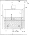
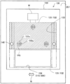
次に、紙幣取扱ユニット200を筐体110から引き出した後に、その収納位置に復帰させる様子について説明する。図9は傾斜正面板112と離間している紙幣取扱ユニット200を収納位置に復帰させる際の機器配置やその駆動状況の様子を側方側から表して説明する説明図、図10は傾斜正面板112と離間している紙幣取扱ユニット200を収納位置に復帰させる際の機器配置やその駆動状況の様子を図9におけるA方向から表して説明する説明図である。
紙幣取扱ユニット200が傾斜正面板112から離れている状態では、筐体110が入出金口115の周囲の傾斜正面板112に備える位置決めローラー140は、シャッタ131の傾斜側壁131bと非接触である。よって、シャッタ131は、係合ピン145や支持脚132aで支持されているとは言えフリーであるので、図9における紙面奥側から手前側に向かう方向および図10における左右方向、即ち入出金口115の開口幅方向において変位可能である。なお、このように変位可能な様子は、図5や図6において左右方向の矢印Wとして示されている。
このようにシャッタ131が変位可能な状態で、紙幣取扱ユニット200は、傾斜正面板112の側に押し込まれて収納される。そうすると、その収納過程で、筐体110の位置決めローラー140は、紙幣取扱ユニット200のシャッタ131の傾斜側壁131bに接触する。図10では、一方の位置決めローラー140のみがシャッタ131の傾斜側壁131bに接触した状況を示している。この状況では、一方の位置決めローラー140は、シャッタ131の傾斜側壁131bとの接触により、図10の黒塗り矢印に示す方向の力を、傾斜側壁131bを介してシャッタ131及ぼす。そうすると、変位可能であったシャッタ131は、図10の黒塗り矢印方向の力を受けて、図10の白塗り矢印に変位するので、それまで傾斜側壁131bと非接触であった他方の位置決めローラー140が傾斜側壁131bと接触する。こうして入出金口115の開口幅方向の二つの位置決めローラー140がシャッタ131の傾斜側壁131bにほぼ均等に接触すると、紙幣取扱ユニット200のそれ以上の押し込みは不要となり、紙幣取扱ユニット200は、筐体110の位置決めローラー140を介して所定の収納位置に収納されることになる。
こうして紙幣取扱ユニット200が収納位置に収納された状況では、入出金口115の開口幅方向の二つの位置決めローラー140とシャッタ131の傾斜側壁131bとの均等な接触により、紙幣取扱ユニット200の収納前には崩れていた入出金口115とシャッタ131との相対的な位置関係は、入出金口115の開口幅方向において均等となるよう、位置合わせされる。つまり、筐体110の有する位置決めローラー140は、紙幣取扱ユニット200の凹状開口部206を閉鎖するシャッタ131の傾斜側壁131bに接触することにより、入出金口115に対するシャッタ131の変位を誘起して、シャッタ131と入出金口115との相対的な位置合わせを図る。図9や図10では、位置決めローラー140は、凹状開口部206を閉鎖した状態のシャッタ131に対して接触する様子を示しているが、位置決めローラー140の配設位置は、入出金口115の上端よりも上方であることから、紙幣取扱ユニット200の収納の際、シャッタ131が凹状開口部206を開放していてもよい。
紙幣取扱ユニット200が既述したように収納位置に収納されると、入出金口115の開口幅方向の二つの位置決めローラー140は、シャッタ131の傾斜側壁131bにほぼ均等に接触している。よって、シャッタ131は、ATM100の運用期間において、シャッタ両側の傾斜側壁131bに接触する位置決めローラー140の案内を受けながら、入出金口115とこれに対向する凹状開口部206、並びにその間のケース開口部134を開閉駆動する。この際、位置決めローラー140は、シャッタ131の開閉動作に応じて従属回転する。
以上説明した構成を備える本実施形態のATM100は、筐体110の傾斜正面板112に紙葉類の受入口と放出口を兼ねる入出金口115を備え、筐体110の収納位置に収納されると入出金口115に対向する凹状開口部206を有する紙幣取扱ユニット200のユニット傾斜面207に、シャッタケース133を介してシャッタ機構130を装着して備える。このシャッタ機構130は、入出金口115と紙幣取扱ユニット200との間にシャッタ131と共に介在し、シャッタ131により入出金口115と凹状開口部206とを開閉する。その上で、本実施形態のATM100は、紙幣取扱ユニット200に、凹状開口部206を開閉するシャッタ131を凹状開口部206および入出金口115の開口幅方向に変位可能に支持し、筐体110には、シャッタ131の傾斜側壁131bと向かい合って当該側壁に接触すると、入出金口115に対するシャッタ131の開口幅方向の変位を誘起する位置決めローラー140を備える。本実施形態のATM100では、筐体110の傾斜正面板112に近づくよう紙幣取扱ユニット200をその収納位置に近づければ、仮にシャッタ131が開口幅方向において入出金口115と相対的に位置ズレしていても(図10参照)、この位置ズレが矯正されるよう、シャッタ131を開口幅方向に変位させて、シャッタ131と入出金口115との相対的な位置合わせを図ることができる。この結果、本実施形態のATM100によれば、シャッタ機構130を紙幣取扱ユニット200に装着することで、シャッタ機構130に付属のケーブル類を、シャッタ機構自体の変位については勿論のこと、紙幣取扱ユニット200の引出・収納に支障が起きないよう、簡便に取り回しできると共に、シャッタ機構130の周辺に十分な作業スペースを確保して、シャッタ機構130の取付作業や保守作業を簡便とできる。これらに加え、本実施形態のATM100によれば、紙幣取扱ユニット200の引出・収納の度の筐体110の入出金口115とシャッタ131との位置調整の簡便化を図ることができる。
本実施形態のATM100は、シャッタ131をシャッタ機構130において変位可能に支持し(図8参照)、このシャッタ機構130そのものを紙幣取扱ユニット200のユニット傾斜面207に装着固定した。よって、シャッタ機構130を装着すればよく、簡便となる。
本実施形態のATM100は、シャッタ131を入出金口115の開口幅方向に変位しても、入出金口115の全域、および凹状開口部206の全域を閉鎖するので、入出金口115の開口上下方向の位置調整が不要となり、簡便である。
本実施形態のATM100は、シャッタ131のシャッタ側壁を、凹状開口部206の側ほど幅広となるように傾斜した傾斜側壁131bとし、この傾斜側壁131bに位置決めローラー140を接触させて、シャッタ131に開口幅方向の力を及ぼし、シャッタ131を開口幅方向に変位させる。よって、本実施形態のATM100によれば、より確実、且つ円滑にシャッタ131の変位を起こすことで、入出金口115とシャッタ131との位置調整をより簡便とできる。この場合、入出金口115に対するシャッタ131の位置関係は、開口幅方向両側において均等となることから、シャッタ131による入出金口115の閉鎖状態での見栄えの向上や、シール材を併用した効果的な防塵・防滴を図ることができる。
これに加え、本実施形態のATM100は、位置決めローラー140を、入出金口115の上端よりも上方に配設しているので、紙幣取扱ユニット200の凹状開口部206を閉鎖しているシャッタ131であっても、凹状開口部206を開放しているシャッタ131であっても、その傾斜側壁131bに接触させる。よって、本実施形態のATM100によれば、紙幣取扱ユニット200を収納する際のシャッタ131の開口開放・閉鎖を問わず、入出金口115とシャッタ131との位置調整を図ることができる。しかも、本実施形態のATM100では、入出金口115の開口幅方向の二つの位置決めローラー140をシャッタ131の傾斜側壁131bにほぼ均等に接触させているので、ATM100の運用期間において、シャッタ131を、シャッタ両側の位置決めローラー140にて案内しながら支障なく開閉駆動できる。この際、位置決めローラー140は、シャッタ131の開閉動作に応じて従属回転するので、シャッタ131の開閉駆動を妨げることはなく、円滑なシャッタ駆動をもたらすことができる。
次に、他の実施形態について説明する。この実施形態は、筐体110の傾斜正面板112を、紙幣取扱ユニット200に装着済みのシャッタ機構130に対して近づけて、入出金口115とシャッタ131との位置決め調整を図る点に特徴がある。図11は紙幣取扱ユニット200から離間している傾斜正面板112をシャッタ機構130に近接することで位置調整を図る機器構成を側方側から表して説明する説明図である。
図示するように、この実施形態の傾斜正面板112は、図11における上方側の図示しない揺動支点を中心に揺動可能とされている。傾斜正面板112が図示するようにシャッタ機構130から離れている状況では、シャッタ131は、既述したように入出金口115の開口幅方向に変位可能である。よって、紙幣取扱ユニット200の保守点検等の際に紙幣取扱ユニット200がその収納位置におおよそ配置されていれば、次のようにして入出金口115とシャッタ131とを位置合わせできる。紙幣取扱ユニット200がおおよその収納位置にあれば、傾斜正面板112をシャッタ機構130の側に揺動する過程で、位置決めローラー140は、既述したように少なくとも一方がシャッタ131の傾斜側壁131bに接触し、シャッタ131を変位させる。よって、この実施形態によって、既述した効果を奏することができる。
図12はまた別の実施形態における要部を図4相当に概略的に示す説明図である。この実施形態は、位置決めローラー140に代えて、位置決め半球体141を開口傾斜側壁112aから突出して備える。この実施形態であっても、位置決め半球体141がシャッタ131の傾斜側壁131bと接触することで、シャッタ131の変位を誘起するので、既述した効果を奏することができる。この他、位置決め半球体141に代え、半球状の先端を有する棒状体としてもよい。また、開口傾斜側壁112aの壁面に、低摩擦係数の樹脂材を平面的に配設したり、樹脂製の突起を点在配設するようにしてもよい。
図13はシャッタ機構130そのものを開口幅方向に変位可能とした実施形態の要部を図4相当に概略的に示す説明図、図14はシャッタ機構130そのものを開口幅方向に変位可能とした実施形態のシャッタ機構130を正面視して図5相当に示す説明図、図15はシャッタ機構変位部138を図14の15-15線に沿って断面視して示す説明図である。この実施形形態では、図13~図14に示すように、ベースプレート132は、シャッタ131の凸状片131aの厚みとほぼ同じ幅で支持脚132aを備え、この支持脚132aにて凸状片131aを挟持して係合ピン145にてシャッタ131を係合する。つまり、シャッタ131は、変位不能にベースプレート132と一体とされ、このベースプレート132と共に、既述したように開閉駆動する。その上で、シャッタ機構130は、シャッタケース133に、シャッタ機構変位部138を備える。
このシャッタ機構変位部138は、図15に示すように、紙幣取扱ユニット200のユニット傾斜面207に締め込み固定された六角穴付ボルト138aと、シャッタケース133に形成された長円形の第1長孔138bと、第2長孔138cとからなる。第1長孔138bは、六角穴付ボルト138aのボルトヘッドより大径の長円形とされ、第2長孔138cは、六角穴付ボルト138aのボルト部位より僅かに大径の長円形とされ、シャッタ機構130は、シャッタケース133ごと、第2長孔138cの軸方向に沿って、変位可能に紙幣取扱ユニット200のユニット傾斜面207に装着固定されている。この実施形態では、紙幣取扱ユニット200は、シャッタ機構130そのものをシャッタ機構変位部138にて既述したように入出金口115の開口幅方向に変位可能に装着して備え、シャッタ131を、位置決めローラー140と傾斜側壁131bとの接触により、シャッタ機構130ごと変位可能とする。よって、この実施形態によっても、既述した効果を奏することができる。この場合、シャッタケース133の底面とユニット傾斜面207との間に、低摩擦係数の樹脂シートを介在させたり、平面摺動をもたらすベアリングを配置すれば、シャッタ機構130を、位置決めローラー140と傾斜側壁131bとの接触により、より容易に変位させることができる。
本発明は、上述の実施形態に限られるものではなく、その趣旨を逸脱しない範囲において種々の構成で実現することができる。例えば、発明の概要の欄に記載した各形態中の技術的特徴に対応する実施形態の技術的特徴は、上述の課題の一部又は全部を解決するために、或いは、上述の効果の一部又は全部を達成するために、適宜、差し替えや、組み合わせを行うことが可能である。また、その技術的特徴が本明細書中に必須なものとして説明されていなければ、適宜、削除することが可能である。この他、本発明は、特許請求の範囲に記載した形態以外の種々の形態で実現することも可能であり、例えば、紙幣のみを取り扱うATMにおける紙葉類取扱装置や、紙幣と硬貨の両者を取り扱うATMにおける紙葉類取扱装置としての形態等で実現することが可能である。
上記の実施形態では、筐体110に対して、紙幣取扱ユニット200が後方より収納引出されるATM100について記述したが、逆に固定された紙幣取扱ユニット200に対して筐体110が前方に収納引出される構造にも適用可能である。さらに、設置環境においても屋外や屋内で使用するATM100にも適用できる。
なお、前述した各実施形態における構成要素の中の、請求項で記載された要素以外の要素は、付加的な要素であり、適宜省略可能である。
上記記載は実施例についてなされたが、本発明はそれに限らず、本発明の趣旨と添付の請求の範囲の範囲内で種々の変更および修正をすることができることは当業者に明らかである。
100 現金自動取引装置(ATM)
102 本体制御部
103 外部インタフェース部
104 係員操作部
105 外部記憶装置
106 電源部
110 筐体
111 上部正面板
112 傾斜正面板
112a 開口傾斜側壁
113 カードスロット
114 第1顧客操作部
115 入出金口
116 第2顧客操作部
120 明細票処理ユニット
130 シャッタ機構
131 シャッタ
131a 凸状片
131b 傾斜側壁
132 ベースプレート
132a 支持脚
133 シャッタケース
134 ケース開口部
135 シャッタ収納部
138 シャッタ機構変位部
138a 六角穴付ボルト
138b 第1長孔
138c 第2長孔
140 位置決めローラー
141 位置決め半球体
142 保持ブラケット
144 回転軸
145 係合ピン
200 紙幣取扱ユニット
206 凹状開口部
207 ユニット傾斜面
M シャッタ駆動モーター
W 矢印
Claims (7)
- 紙葉類取扱装置であって、
紙葉類の受入口と放出口を兼ねる受入放出口を接客操作面に備えた筐体と、
紙葉類出入り用の凹状開口部を有し、前記筐体の内部の所定の収納位置に収納されると前記受入放出口に前記凹状開口部を対向させる紙葉類取扱ユニットと、
前記対向した前記受入放出口と前記凹状開口部の開口との間にシャッタを介在させて有し、該シャッタを駆動して前記受入放出口と前記凹状開口部とを開閉するシャッタ機構とを備え、
前記紙葉類取扱ユニットは、前記凹状開口部を開閉する前記シャッタを変位可能に支持した状態で、前記シャッタ機構を前記凹状開口部の側に装着して備え、
前記筐体は、前記収納位置に収納される前記紙葉類取扱ユニットの前記凹状開口部を閉鎖する前記シャッタとの接触により、前記受入放出口に対する前記シャッタの変位を誘起して、前記シャッタと前記受入放出口との相対的な位置合わせを図るシャッタ変位誘起部を備える、紙葉類取扱装置。 - 前記シャッタ機構は、前記シャッタを変位可能に支持して、前記紙葉類取扱ユニットに装着されている請求項1に記載の紙葉類取扱装置。
- 前記紙葉類取扱ユニットは、前記シャッタを前記シャッタ機構ごと変位可能に支持して備える請求項1に記載の紙葉類取扱装置。
- 前記シャッタは、開閉駆動方向と交差する前記受入放出口の開口幅方向に変位可能に支持されている請求項1から請求項3のいずれか一項に記載の紙葉類取扱装置。
- 前記シャッタは、前記開口幅方向のシャッタ側壁を、前記凹状開口部の側ほど幅広となるように傾斜した傾斜側壁とし、
前記シャッタ変位誘起部は、前記シャッタの前記傾斜側壁と接触して、前記シャッタに前記開口幅方向の力を及ぼす、請求項4項に記載の紙葉類取扱装置。 - 前記シャッタ変位誘起部は、前記シャッタの前記傾斜側壁と接触し、前記シャッタの開閉動作に応じて従属回転する回転ローラーを有する請求項5に記載の紙葉類取扱装置。
- 前記筐体は、前記受入放出口の前記開口幅方向の放出口側壁を、前記シャッタの前記傾斜側壁と対向して傾斜した傾斜側壁とする請求項4から請求項6のいずれか一項に記載の紙葉類取扱装置。
Applications Claiming Priority (2)
| Application Number | Priority Date | Filing Date | Title |
|---|---|---|---|
| JP2013-246969 | 2013-11-29 | ||
| JP2013246969A JP6030537B2 (ja) | 2013-11-29 | 2013-11-29 | 紙葉類取扱装置 |
Publications (1)
| Publication Number | Publication Date |
|---|---|
| WO2015080018A1 true WO2015080018A1 (ja) | 2015-06-04 |
Family
ID=53198962
Family Applications (1)
| Application Number | Title | Priority Date | Filing Date |
|---|---|---|---|
| PCT/JP2014/080745 WO2015080018A1 (ja) | 2013-11-29 | 2014-11-20 | 紙葉類取扱装置 |
Country Status (3)
| Country | Link |
|---|---|
| JP (1) | JP6030537B2 (ja) |
| CN (1) | CN104680643B (ja) |
| WO (1) | WO2015080018A1 (ja) |
Families Citing this family (1)
| Publication number | Priority date | Publication date | Assignee | Title |
|---|---|---|---|---|
| JP7322587B2 (ja) * | 2019-08-16 | 2023-08-08 | 沖電気工業株式会社 | 媒体取引装置 |
Citations (4)
| Publication number | Priority date | Publication date | Assignee | Title |
|---|---|---|---|---|
| JPS6215693A (ja) * | 1985-07-15 | 1987-01-24 | 株式会社日立製作所 | シヤツタ機構 |
| JPH08329311A (ja) * | 1995-06-02 | 1996-12-13 | Hitachi Ltd | 電子機器媒体出し入れ口実装方式 |
| JP2011170655A (ja) * | 2010-02-19 | 2011-09-01 | Hitachi Omron Terminal Solutions Corp | 紙葉類取扱装置 |
| JP2013050769A (ja) * | 2011-08-30 | 2013-03-14 | Fujitsu Frontech Ltd | 自動取引装置 |
Family Cites Families (5)
| Publication number | Priority date | Publication date | Assignee | Title |
|---|---|---|---|---|
| JP4408373B2 (ja) * | 2004-01-23 | 2010-02-03 | 日立オムロンターミナルソリューションズ株式会社 | 紙幣入出金装置 |
| JP4846507B2 (ja) * | 2006-10-11 | 2011-12-28 | 日立オムロンターミナルソリューションズ株式会社 | 現金自動取引装置 |
| JP4889456B2 (ja) * | 2006-11-24 | 2012-03-07 | 日立オムロンターミナルソリューションズ株式会社 | 紙幣入出金装置および紙幣入出金装置制御方法 |
| JP5174469B2 (ja) * | 2008-01-11 | 2013-04-03 | 日立オムロンターミナルソリューションズ株式会社 | 外部シャッター機構及び現金自動取引装置 |
| JP5778073B2 (ja) * | 2012-04-18 | 2015-09-16 | 日立オムロンターミナルソリューションズ株式会社 | 紙葉類取扱装置および紙葉類取扱方法 |
-
2013
- 2013-11-29 JP JP2013246969A patent/JP6030537B2/ja active Active
-
2014
- 2014-11-13 CN CN201410640079.4A patent/CN104680643B/zh active Active
- 2014-11-20 WO PCT/JP2014/080745 patent/WO2015080018A1/ja active Application Filing
Patent Citations (4)
| Publication number | Priority date | Publication date | Assignee | Title |
|---|---|---|---|---|
| JPS6215693A (ja) * | 1985-07-15 | 1987-01-24 | 株式会社日立製作所 | シヤツタ機構 |
| JPH08329311A (ja) * | 1995-06-02 | 1996-12-13 | Hitachi Ltd | 電子機器媒体出し入れ口実装方式 |
| JP2011170655A (ja) * | 2010-02-19 | 2011-09-01 | Hitachi Omron Terminal Solutions Corp | 紙葉類取扱装置 |
| JP2013050769A (ja) * | 2011-08-30 | 2013-03-14 | Fujitsu Frontech Ltd | 自動取引装置 |
Also Published As
| Publication number | Publication date |
|---|---|
| CN104680643B (zh) | 2017-08-18 |
| JP6030537B2 (ja) | 2016-11-24 |
| CN104680643A (zh) | 2015-06-03 |
| JP2015106225A (ja) | 2015-06-08 |
Similar Documents
| Publication | Publication Date | Title |
|---|---|---|
| US11380157B2 (en) | Servicing and mounting features for gaming machine display screens and toppers | |
| KR101148387B1 (ko) | 현금 자동 거래 장치 | |
| US7494049B2 (en) | Shutter mechanism of automated-teller machine | |
| JP5974624B2 (ja) | 紙葉類搬送装置及び紙葉類取扱装置 | |
| JP5238316B2 (ja) | 駐車場管理機 | |
| JP6438642B2 (ja) | 紙葉類取扱装置 | |
| RU2603586C1 (ru) | Устройство обработки носителей и устройство транзакций с носителями | |
| JP6030537B2 (ja) | 紙葉類取扱装置 | |
| JP5377357B2 (ja) | 紙葉類取扱装置 | |
| JP5268687B2 (ja) | 自動取引装置 | |
| EP2509051B1 (en) | Media processing device | |
| KR101077195B1 (ko) | 지엽 취급 장치 | |
| CN103366441B (zh) | 自动交易装置和自动交易装置的防盗结构 | |
| JP2013204358A (ja) | 開閉装置 | |
| CN107341937B (zh) | 一种用于纸质介质传输的开合机构 | |
| JP2014191502A (ja) | 自動取引装置 | |
| JP4321513B2 (ja) | 紙幣収納装置および紙幣処理装置 | |
| CN210488638U (zh) | 一种钱箱导向板复位机构及钱箱 | |
| JP7197860B2 (ja) | 貨幣処理システム及び表示装置 | |
| JPH0877411A (ja) | 紙幣処理機における出金口構造 | |
| KR100874525B1 (ko) | 금융자동화기기의 차단판 개폐장치 | |
| JP6323164B2 (ja) | 自動取引装置 | |
| JP2017102805A (ja) | 自動取引装置 | |
| KR100526582B1 (ko) | 현금입출금기의 리싸이클박스 지지구조 | |
| JP2005046432A (ja) | 遊技媒体貸出装置 |
Legal Events
| Date | Code | Title | Description |
|---|---|---|---|
| 121 | Ep: the epo has been informed by wipo that ep was designated in this application |
Ref document number: 14866591 Country of ref document: EP Kind code of ref document: A1 |
|
| NENP | Non-entry into the national phase |
Ref country code: DE |
|
| 122 | Ep: pct application non-entry in european phase |
Ref document number: 14866591 Country of ref document: EP Kind code of ref document: A1 |