WO2015079800A1 - 弁装置 - Google Patents
弁装置 Download PDFInfo
- Publication number
- WO2015079800A1 WO2015079800A1 PCT/JP2014/076312 JP2014076312W WO2015079800A1 WO 2015079800 A1 WO2015079800 A1 WO 2015079800A1 JP 2014076312 W JP2014076312 W JP 2014076312W WO 2015079800 A1 WO2015079800 A1 WO 2015079800A1
- Authority
- WO
- WIPO (PCT)
- Prior art keywords
- valve
- diaphragm
- outflow port
- valve seat
- inflow
- Prior art date
Links
Images


Classifications
-
- B—PERFORMING OPERATIONS; TRANSPORTING
- B01—PHYSICAL OR CHEMICAL PROCESSES OR APPARATUS IN GENERAL
- B01L—CHEMICAL OR PHYSICAL LABORATORY APPARATUS FOR GENERAL USE
- B01L3/00—Containers or dishes for laboratory use, e.g. laboratory glassware; Droppers
- B01L3/56—Labware specially adapted for transferring fluids
- B01L3/567—Valves, taps or stop-cocks
-
- F—MECHANICAL ENGINEERING; LIGHTING; HEATING; WEAPONS; BLASTING
- F16—ENGINEERING ELEMENTS AND UNITS; GENERAL MEASURES FOR PRODUCING AND MAINTAINING EFFECTIVE FUNCTIONING OF MACHINES OR INSTALLATIONS; THERMAL INSULATION IN GENERAL
- F16K—VALVES; TAPS; COCKS; ACTUATING-FLOATS; DEVICES FOR VENTING OR AERATING
- F16K11/00—Multiple-way valves, e.g. mixing valves; Pipe fittings incorporating such valves
- F16K11/02—Multiple-way valves, e.g. mixing valves; Pipe fittings incorporating such valves with all movable sealing faces moving as one unit
- F16K11/022—Multiple-way valves, e.g. mixing valves; Pipe fittings incorporating such valves with all movable sealing faces moving as one unit comprising a deformable member
-
- F—MECHANICAL ENGINEERING; LIGHTING; HEATING; WEAPONS; BLASTING
- F16—ENGINEERING ELEMENTS AND UNITS; GENERAL MEASURES FOR PRODUCING AND MAINTAINING EFFECTIVE FUNCTIONING OF MACHINES OR INSTALLATIONS; THERMAL INSULATION IN GENERAL
- F16K—VALVES; TAPS; COCKS; ACTUATING-FLOATS; DEVICES FOR VENTING OR AERATING
- F16K11/00—Multiple-way valves, e.g. mixing valves; Pipe fittings incorporating such valves
- F16K11/02—Multiple-way valves, e.g. mixing valves; Pipe fittings incorporating such valves with all movable sealing faces moving as one unit
- F16K11/04—Multiple-way valves, e.g. mixing valves; Pipe fittings incorporating such valves with all movable sealing faces moving as one unit comprising only lift valves
- F16K11/052—Multiple-way valves, e.g. mixing valves; Pipe fittings incorporating such valves with all movable sealing faces moving as one unit comprising only lift valves with pivoted closure members, e.g. butterfly valves
- F16K11/0525—Multiple-way valves, e.g. mixing valves; Pipe fittings incorporating such valves with all movable sealing faces moving as one unit comprising only lift valves with pivoted closure members, e.g. butterfly valves the closure members being pivoted around an essentially central axis
-
- F—MECHANICAL ENGINEERING; LIGHTING; HEATING; WEAPONS; BLASTING
- F16—ENGINEERING ELEMENTS AND UNITS; GENERAL MEASURES FOR PRODUCING AND MAINTAINING EFFECTIVE FUNCTIONING OF MACHINES OR INSTALLATIONS; THERMAL INSULATION IN GENERAL
- F16K—VALVES; TAPS; COCKS; ACTUATING-FLOATS; DEVICES FOR VENTING OR AERATING
- F16K27/00—Construction of housing; Use of materials therefor
- F16K27/02—Construction of housing; Use of materials therefor of lift valves
- F16K27/0263—Construction of housing; Use of materials therefor of lift valves multiple way valves
-
- F—MECHANICAL ENGINEERING; LIGHTING; HEATING; WEAPONS; BLASTING
- F16—ENGINEERING ELEMENTS AND UNITS; GENERAL MEASURES FOR PRODUCING AND MAINTAINING EFFECTIVE FUNCTIONING OF MACHINES OR INSTALLATIONS; THERMAL INSULATION IN GENERAL
- F16K—VALVES; TAPS; COCKS; ACTUATING-FLOATS; DEVICES FOR VENTING OR AERATING
- F16K31/00—Actuating devices; Operating means; Releasing devices
- F16K31/02—Actuating devices; Operating means; Releasing devices electric; magnetic
- F16K31/06—Actuating devices; Operating means; Releasing devices electric; magnetic using a magnet, e.g. diaphragm valves, cutting off by means of a liquid
- F16K31/0603—Multiple-way valves
- F16K31/0641—Multiple-way valves the valve member being a diaphragm
-
- F—MECHANICAL ENGINEERING; LIGHTING; HEATING; WEAPONS; BLASTING
- F16—ENGINEERING ELEMENTS AND UNITS; GENERAL MEASURES FOR PRODUCING AND MAINTAINING EFFECTIVE FUNCTIONING OF MACHINES OR INSTALLATIONS; THERMAL INSULATION IN GENERAL
- F16K—VALVES; TAPS; COCKS; ACTUATING-FLOATS; DEVICES FOR VENTING OR AERATING
- F16K31/00—Actuating devices; Operating means; Releasing devices
- F16K31/02—Actuating devices; Operating means; Releasing devices electric; magnetic
- F16K31/06—Actuating devices; Operating means; Releasing devices electric; magnetic using a magnet, e.g. diaphragm valves, cutting off by means of a liquid
- F16K31/10—Actuating devices; Operating means; Releasing devices electric; magnetic using a magnet, e.g. diaphragm valves, cutting off by means of a liquid with additional mechanism between armature and closure member
- F16K31/105—Actuating devices; Operating means; Releasing devices electric; magnetic using a magnet, e.g. diaphragm valves, cutting off by means of a liquid with additional mechanism between armature and closure member for rotating valves
-
- F—MECHANICAL ENGINEERING; LIGHTING; HEATING; WEAPONS; BLASTING
- F16—ENGINEERING ELEMENTS AND UNITS; GENERAL MEASURES FOR PRODUCING AND MAINTAINING EFFECTIVE FUNCTIONING OF MACHINES OR INSTALLATIONS; THERMAL INSULATION IN GENERAL
- F16K—VALVES; TAPS; COCKS; ACTUATING-FLOATS; DEVICES FOR VENTING OR AERATING
- F16K7/00—Diaphragm valves or cut-off apparatus, e.g. with a member deformed, but not moved bodily, to close the passage ; Pinch valves
- F16K7/12—Diaphragm valves or cut-off apparatus, e.g. with a member deformed, but not moved bodily, to close the passage ; Pinch valves with flat, dished, or bowl-shaped diaphragm
- F16K7/14—Diaphragm valves or cut-off apparatus, e.g. with a member deformed, but not moved bodily, to close the passage ; Pinch valves with flat, dished, or bowl-shaped diaphragm arranged to be deformed against a flat seat
- F16K7/16—Diaphragm valves or cut-off apparatus, e.g. with a member deformed, but not moved bodily, to close the passage ; Pinch valves with flat, dished, or bowl-shaped diaphragm arranged to be deformed against a flat seat the diaphragm being mechanically actuated, e.g. by screw-spindle or cam
-
- B—PERFORMING OPERATIONS; TRANSPORTING
- B01—PHYSICAL OR CHEMICAL PROCESSES OR APPARATUS IN GENERAL
- B01L—CHEMICAL OR PHYSICAL LABORATORY APPARATUS FOR GENERAL USE
- B01L2200/00—Solutions for specific problems relating to chemical or physical laboratory apparatus
- B01L2200/06—Fluid handling related problems
- B01L2200/0605—Metering of fluids
-
- B—PERFORMING OPERATIONS; TRANSPORTING
- B01—PHYSICAL OR CHEMICAL PROCESSES OR APPARATUS IN GENERAL
- B01L—CHEMICAL OR PHYSICAL LABORATORY APPARATUS FOR GENERAL USE
- B01L2400/00—Moving or stopping fluids
- B01L2400/06—Valves, specific forms thereof
- B01L2400/0633—Valves, specific forms thereof with moving parts
- B01L2400/0638—Valves, specific forms thereof with moving parts membrane valves, flap valves
Definitions
- the present invention relates to a valve device used in various analytical devices such as a chemical inspection device, an environmental analysis device, or a biotechnology research equipment.
- valve device that controls the flow rate of fluid used for measurement.
- a diaphragm is used as a valve opening / closing mechanism in order to realize excellent chemical resistance and the like.
- the diaphragm forms a partition that partitions the valve chamber, and receives a driving force from the outside to switch the fluid flow path.
- an inflow port and two outflow ports are provided in the housing so as to communicate with the valve chamber, and the diaphragm swings to close one outflow port and the other. Open outflow port and switch fluid flow path.
- the internal volume of the valve chamber changes, and the fluid corresponding to the change amount (pumping volume) of the internal volume is pushed out to the outflow port. For this reason, it has been difficult to improve the accuracy of the outflow amount.
- Patent Document 1 discloses a valve device in which the area of the inflow port is set to be twice or more than the area of the outflow port.
- the present invention has been devised in view of the above circumstances, and it is possible to reduce the pumping volume and control the outflow amount accurately without making the cross-sectional area of the inflow port and the cross-sectional area of the outflow port greatly different.
- the main purpose is to provide a valve device that enables this.
- the present invention includes a recess provided in a casing, a diaphragm that forms a valve chamber that is a space through which the fluid flows by covering the recess, and a fluid that opens in the recess and flows into the valve chamber.
- An inflow port through which the fluid flows in an outflow port that opens in the recess and through which the fluid flows out from the valve chamber, and swinging the diaphragm, the diaphragm is brought into close contact with a valve seat formed by the opening of the outflow port.
- a valve device having diaphragm driving means for closing or opening the outflow port by separating from each other, wherein the concave portion is directed from the valve seat side toward an inflow opening where the inflow port communicates with the valve chamber.
- the valve chamber has a vertical direction in which the outflow port and the inflow port are arranged, and a width direction orthogonal to the vertical direction and the depth direction.
- the inclined portion since the first convex portions are provided on both sides in the width direction of the inflow opening, the inclined portion has a tapered shape in which the width gradually increases from the inflow opening toward the valve seat. To do.
- the first protrusion gradually increases in inclination with respect to a plane passing through the inflow opening from both sides in the width direction of the valve chamber toward the inflow opening.
- the outflow port is provided with two systems of a first outflow port and a second outflow port, and the diaphragm driving means swings the diaphragm so that the diaphragm
- the fluid in the valve chamber is caused to adhere to the first outflow port or the second valve seat by closely contacting either the first valve seat formed by the opening of the first outflow port or the second valve seat formed by the opening of the second outflow port.
- the first inclining portion whose depth gradually increases from the first valve seat side toward the inflow opening where the inflow port communicates with the valve chamber; and A second inclined portion that gradually increases in depth from the valve seat side toward the inflow opening, and the first outflow port, the inflow port, and the second outflow port are arranged in this order, Inclined part and front
- the second inclined portion is preferably a width from the inlet opening toward the first valve seat and second valve seat is gradually increased.
- the inclined portion has a taper angle of 30 to 60 degrees in a plan view as viewed from the diaphragm side.
- a holding surface that holds the diaphragm in close contact with the diaphragm is formed at a peripheral edge of the concave portion, and a depth of the first convex portion from the holding surface is less than 0 mm. Larger is desirable.
- the inclined portion is provided with a second convex portion that protrudes toward the diaphragm.
- the depth of the inflow opening is larger than the depth of the valve seat.
- a difference between the depth of the inflow opening and the depth of the valve seat is 0.3 mm or more.
- valve seat protrudes toward the diaphragm side.
- the inclined portion is inclined at an angle of 3 to 15 degrees with respect to a plane passing through the inflow opening.
- the casing includes a first block in which the recess is formed, and a second block that is fixed to the first block and holds the diaphragm, and the first block and the
- the valve seat depth DA is 1.5 to 2.5 mm
- the inflow opening depth DB is 2.0 to 3.0 mm. It is desirable to be.
- the diaphragm driving means includes a coil and a plunger that applies displacement to the diaphragm by energizing the coil.
- the internal volume of the valve chamber increases.
- the ratio of the pumping volume to the internal volume of the valve chamber is reduced, and most of the fluctuation of the internal volume of the valve chamber accompanying the oscillation of the diaphragm is absorbed as the fluctuation of the internal pressure of the valve chamber. Therefore, the pumping volume can be sufficiently reduced without significantly differenting the cross-sectional area of the inflow port and the cross-sectional area of the outflow port.
- the inclined portion is formed so that the fluid flows smoothly from the inflow opening to the valve seat side, the fluid is suppressed from staying inside the valve chamber. Furthermore, by providing the first convex portions on both sides in the width direction of the inflow opening, the inclined portion has a tapered shape in which the width gradually increases from the inflow opening toward the valve seat. Thereby, the cross-sectional area of the flow path is sufficiently ensured even in the vicinity of the outflow opening, the smooth flow of the fluid is not hindered, and the retention of the fluid is further suppressed.
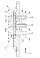
- FIG. 5 is a sectional view taken along line AA in FIG. 4.
- FIG. 5A is a cross-sectional view taken along line BB in FIG. 4
- FIG. 5B is a cross-sectional view taken along line CC in FIG.
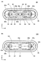
- It is a top view which shows the flow of the fluid in a valve chamber. It is the top view which looked at the modification of the flow path block from the diaphragm side.
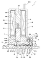
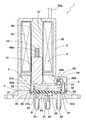
- FIG. 1 and 2 are cross-sectional views of the valve device 1 of the present embodiment.
- FIG. 1 shows a non-energized state in which energization to a solenoid coil 55 described later is cut off
- FIG. 2 shows an energized state in which the solenoid coil 55 is energized.
- the valve device 1 of the present embodiment includes a casing 2 that contains a fluid flow path, a swing valve 4 that is swingable with respect to the casing 2, and a swing.
- a valve driving unit 5 diaphragm driving means for driving the valve 4 and a frame 6 for supporting the casing 2 and the valve driving unit 5 are provided.
- the casing 2 includes a flow path block 20 (first block) and a sub-block 3 (second block).
- the flow path block 20 includes, for example, one or more of PPS (polyphenylene sulfide), PEEK (polyether ether ketone), and PBT (polybutylene tphthalate) as a resin component. It is comprised with the resin material.
- PPS polyphenylene sulfide
- PEEK polyether ether ketone
- PBT polybutylene tphthalate
- the flow path block 20 includes a recess 22 constituting a valve chamber 21 that is a space through which fluid flows, an inflow port 23 (Common port) communicating with the valve chamber 21, and an NC (Normally Close) outflow port 24 (first outflow port). And a NO (Normally Open) outflow port 25 (second outflow port) and a holding surface 26 for holding the swing valve 4.
- the inflow port 23 is always open, and fluid is supplied from the inflow port 23 into the valve chamber 21.
- the NC outflow port 24 is closed, the NO outflow port 25 is opened, and the fluid flowing into the valve chamber 21 from the inflow port 23 flows along the arrow A and flows out from the NO outflow port 25. Is done.
- the sub-block 3 is formed of, for example, a resin material, and includes a housing portion 31 that houses the swing valve 4 and plungers 51 and 52 described later, and a pressing portion 32 that presses the swing valve 4 against the holding surface 26.
- the sub block 3 is attached to the mating surface 27 in which the recess 22 of the flow path block 20 is formed, and is fixed to the flow path block 20 with a screw (not shown) or the like.
- the swing valve 4 includes a diaphragm 41 having elasticity, a swing member 42 integrated with the diaphragm 41, and a shaft member 43 that supports the swing member 42 so as to be swingable.
- the diaphragm 41 is formed of, for example, a rubber material, and is attached to the casing 2 so as to cover the recess 22, thereby forming the valve chamber 21 with the recess 22.
- the swing member 42 is formed of, for example, a resin material and is disposed above the inflow port 23.
- the shaft member 43 is made of, for example, a metal material.
- the shaft member 43 is provided substantially perpendicular to the inflow port 23 above the inflow port 23, and both ends thereof are supported by the sub-block 3.
- the diaphragm 41 has an outer peripheral portion 41a that extends outward.
- the outer peripheral portion 41 a is in close contact with the flow path block 20 by being sandwiched and held and restrained by the holding surface 26 of the flow path block 20 and the pressing portion 32 of the sub block 3. As a result, the valve chamber 21 is sealed and fluid leakage is prevented.
- the valve drive unit 5 includes a first plunger (movable iron core) 51, a second plunger 52, a first coil spring 53, a second coil spring 54, a solenoid coil 55, and a fixed iron core 56.
- the first plunger 51 is disposed above the NC outflow port 24.
- the first plunger 51 is inserted into a coil bobbin 57 around which the solenoid coil 55 is wound.
- the first coil spring 53 is loaded in a recess 56 a formed in the fixed iron core 56. One end of the first coil spring 53 is in contact with the bottom of the recess 56 a of the fixed iron core 56, and the other end is in contact with the top surface of the first plunger 51.
- the first coil spring 53 pushes down the first plunger 51 toward the abutting portion 42 a of the swing member 42, and accordingly, the tip 51 b of the first plunger 51 is brought into contact with the swing member 42. 42a is pressed.
- the spring load (elastic force) of the first coil spring 53 is set larger than the spring load of the second coil spring 54.
- the second plunger 52 is disposed above the NO outflow port 25.
- the second plunger 52 is formed with a cylindrical portion 52a into which the second coil spring 54 is inserted, and a bowl-shaped tip portion 52b formed at the edge of the cylindrical portion 52a.
- One end of the second coil spring 54 is in contact with the distal end portion 52 b of the second plunger 52, and the other end is in contact with the bottom surface of the frame 6.
- the second coil spring 54 pushes down the second plunger 52 toward the abutting portion 42 b of the swinging member 42, and accordingly, the distal end portion 52 b of the second plunger 52 is brought into contact with the swinging member 42. 42b is pressed.
- the solenoid coil 55 is wound around a cylindrical coil bobbin 57.
- the solenoid coil 55 generates an electromagnetic force when energized.
- a predetermined current flows through the solenoid coil 55 so as to generate an electromagnetic force larger than the elastic force of the first coil spring 53.
- the frame 6 is provided on the upper part of the sub-block 3.
- the frame 6 accommodates the first plunger 51, the first coil spring 52, the solenoid coil 55, the fixed iron core 56, and the coil bobbin 57.
- the solenoid coil 55, the fixed iron core 56, and the coil bobbin 57 are fixed by the frame 6.
- the second coil spring 54 is loaded in a recess provided in the sub-block 3.
- the second coil spring 54 abuts against the bottom of the concave portion of the sub-block 3 and generates an elastic force.
- a cable 55 a for supplying power to the solenoid coil 55 is drawn into the frame 6.
- the opening / closing operation of the valve device 1 will be described.
- the posture of the oscillating valve 4 is normally set as shown in FIG. In the figure, the position rotated counterclockwise is maintained, the NC outflow port 24 is closed, and the NO outflow port 25 is opened.
- the fluid flowing into the valve chamber 21 from the inflow port 23 is discharged from the NO outflow port 25.
- the first plunger 51 moves in a direction in which the first coil spring 53 is compressed by the electromagnetic force as shown in FIG.
- the tip 52b of the second plunger 52 presses the contact part 42b of the swing member 42, whereby the swing valve 4 is rotated clockwise in the figure and the NO outflow port 25 is closed.
- the NC outflow port 24 is opened.
- the fluid flowing into the valve chamber 21 from the inflow port 23 is discharged from the NC outflow port 24.
- the flow path block 20 is formed with a recess 22 that partitions the valve chamber 21.
- the recess 22 is formed to be recessed from the mating surface 27 to which the sub-block 3 is joined.
- an NC outflow nipple 29b, an inflow nipple 29a, and an NO outflow nipple 29c are formed so as to protrude from the back surface opposite to the mating surface 27.
- the inflow port 23 is formed through the inflow nipple 29 a from the recess 22.
- the NC outflow port 24 extends from the recess 22 through the NC outflow nipple 29b, and the NO outflow port 25 extends from the recess 22 through the NO outflow nipple 29c.
- the NC outflow port 24, the inflow port 23, and the NO outflow port 25 are arranged in this order.
- the vertical direction in which the NC outflow port 24, the inflow port 23 and the NO outflow port 25 are arranged is the vertical direction X
- the depth direction in which the recess 22 is formed is the depth direction Z
- the vertical direction X and the depth are defined as a width direction Y.
- the inflow port 23 has an inflow opening 23 a that opens facing the recess 22.
- the inflow opening 23 a is formed in communication with the valve chamber 21.
- the inflow port 23 allows fluid to flow into the valve chamber 21 from the inflow opening 23a.
- the NC outflow port 24 and the NO outflow port 25 also have outflow openings 24 a and 25 a that open toward the recess 22.
- the outflow openings 24a and 25a are formed in communication with the valve chamber 21, and the NC outflow port 24 and the NO outflow port 25 allow fluid to flow out of the valve chamber 21 through the outflow openings 24a and 25a.
- a first valve seat 24b is provided in the outflow opening 24a of the NC outflow port 24, and a second valve seat 25b is provided in the outflow opening 25a of the NO outflow port 25.
- the first valve seat 24b and the second valve seat 25b are formed in a cylindrical shape protruding toward the diaphragm 41 side.
- first valve seat 24b and the second valve seat 25b are formed so as to protrude toward the diaphragm 41, the sealing performance between the first valve seat 24b and the second valve seat 25b and the diaphragm 41 when the port is closed is improved. It is done. Thereby, when the NC outflow port 24 or the NO outflow port 25 is closed, the fluid can be prevented from leaking from the valve chamber 21 to the NC outflow port 24 or the NO outflow port 25.
- a first raised portion 24c is formed on the seat surface at the tip of the first valve seat 24b.
- the first raised portion 24c is raised on the diaphragm 41 side.
- the first raised portion 24c is continuously formed in the circumferential direction on the opening side of the NC outflow port 24, that is, on the inner peripheral portion of the first valve seat 24b.
- the first raised portion 24c further enhances the sealing performance between the first valve seat 24b and the diaphragm 41 when the NC outflow port 24 is closed, and prevents fluid leakage.
- the first raised portion 25c is provided for the second valve seat 25b of the NO outflow port 25 as well.
- the holding surface 26 is provided on the periphery of the recess 22.
- the holding surface 26 and the mating surface 27 are formed in steps with the side wall 22a of the recess 22 in between.
- a second raised portion 26 a that protrudes toward the diaphragm 41 is formed on the inner peripheral portion of the holding surface 26.
- the second raised portion 26a is formed continuously in the circumferential direction. The second raised portion 26a enhances the sealing performance between the holding surface 26 and the outer peripheral portion 41a of the diaphragm 41, and prevents fluid leakage.
- a pair of through holes 28 are formed in the periphery of the recess 22 in a substantially diagonal shape of the main body portion 20a of the flow path block 20.
- the flow path block 20 and the sub-block 3 are fixed by screws that pass through the through hole 28.
- the recess 22 has a first inclined portion 81 and a second inclined portion 82.
- the first inclined portion 81 is formed so that the depth from the diaphragm 41 gradually increases from the first valve seat 24b side toward the inflow opening 23a.
- the 2nd inclination part 82 is also formed so that the depth from the diaphragm 41 may increase gradually toward the inflow opening 23a from the 2nd valve seat 25b side.
- the depth from the diaphragm 41 is a distance in the depth direction Z from the holding surface 26 in close contact with the outer peripheral portion 41 a of the diaphragm 41.
- the first inclined portion 81 and the second inclined portion 82 increase the volume in the vicinity of the inflow opening 23a and increase the internal volume of the entire valve chamber 21. Thereby, the ratio of the pumping volume with respect to the internal volume of the valve chamber 21 is reduced, and most of the fluctuation of the internal volume of the valve chamber 21 due to the swing of the diaphragm 41 is absorbed as the fluctuation of the internal pressure of the valve chamber 21.
- the pumping volume can be reduced sufficiently.
- the first inclined portion 81 gradually reduces the depth of the recess 22 from the diaphragm 41 toward the outflow opening 24a from the inflow opening 23a, a smooth flow path is obtained from the inflow opening 23a to the outflow opening 24a. . As a result, the flow of the fluid in the valve chamber 21 becomes smooth and the retention of the fluid is suppressed.
- the depth DB of the inflow opening 23a with the mating surface 27 as a reference plane is set to the first valve seat 24b and the second valve seat. It becomes larger than the depth DA of 25b.
- the difference DB-DA between the depth DB of the inflow opening 23a and the depth DA of the first valve seat 24b and the second valve seat 25b is preferably 0.3 mm or more, more preferably 0. More than 4mm.
- the depth DA of the first valve seat 24b and the second valve seat 25b is preferably 1.5 mm or more, more preferably 1.8 mm or more, preferably 2.5 mm or less, more preferably 2.2 mm or less. .
- the depth DA of the first valve seat 24b and the second valve seat 25b is less than 1.5 mm, the effect of reducing the pumping volume is reduced.
- the depth DA of the first valve seat 24b and the second valve seat 25b exceeds 2.5 mm, the internal volume of the valve chamber 21 becomes excessively large and fluid may be retained.
- the depth DB of the inflow opening 23a is preferably 2.0 mm or more, more preferably 2.3 mm or more, preferably 3.0 mm or less, more preferably 2.7 mm or less.
- the depth DB of the inflow opening 23a is less than 2.0 mm, the effect of reducing the pumping volume is reduced.
- the depth DB of the inflow opening 23a exceeds 3.0 mm, the internal volume of the valve chamber 21 becomes excessively large, and there is a concern that fluid may stay.
- the inclination angle ⁇ of the first inclined portion 81 and the second inclined portion 82 with respect to the plane passing through the inflow opening 23a is 3 to 15 degrees. It is desirable to be.
- the heel inclination angle ⁇ is less than 3 degrees, the internal volume of the valve chamber 21 does not increase sufficiently, and the effect of reducing the pumping volume is reduced.
- the inclination angle ⁇ exceeds 15 degrees, the internal volume of the valve chamber 21 becomes excessively large, and there is a concern that fluid may stay.
- a first convex portion 83 bulging in a bank shape is formed on the diaphragm 41 side.
- the 1st convex part 83 is provided in the both sides of the width direction Y of the inflow opening 23a. Due to the first convex portion 83, the valve chamber 21 has a gourd shape (dumbbell shape) in plan view.
- the first inclined portion 81 and the second inclined portion 82 are formed in a slope shape in which the depth from the holding surface 26 gradually decreases toward the first convex portion 83.
- the first inclined portion 81 and the second inclined portion 82 are directed from the inflow opening 23a toward the first valve seat 24b and the second valve seat 25b.
- the width is gradually increasing. That is, as shown in FIG. 4, the first inclined portion 81 and the second inclined portion 82 are formed in a tapered shape in a plan view as viewed from the diaphragm 41 side.
- the cross-sectional area of the flow path may be insufficient in the vicinity of the outflow opening 24a. .
- the width of the first inclined portion 81 gradually increases from the inflow opening 23a toward the first valve seat 24b, a sufficient cross-sectional area of the flow path is ensured even in the vicinity of the outflow opening 24a. Therefore, the smooth flow of the fluid is not hindered.
- the fluid flow from the inflow opening 23a toward the outflow opening 25a is the same as described above.
- the depth of the first convex portion 83 from the holding surface 26 is preferably greater than 0 mm, more preferably 0.3 mm or more, preferably 1.0 mm or less, more preferably 0.7 mm or less.
- the depth of the first convex portion 83 from the holding surface 26 refers to the outer end of the first convex portion 83 in the width direction Y and the inner peripheral end of the holding surface 26 (in this embodiment, the second raised portion 26a). ) In the depth direction Z.
- the depth of the first convex portion 83 from the holding surface 26 is less than 0.3 mm, the diaphragm 41 comes into contact with the first convex portion 83 and wears when the valve is closed, so that the durability of the valve device 1 is improved. May decrease.
- the depth from the holding surface 26 of the 1st convex part 83 exceeds 1.0 mm, there exists a possibility that the internal volume of the valve chamber 21 may become large too much, and the retention of a fluid may arise.
- the end portion (inner end portion in the width direction Y) of the first convex portion 83 on the inflow port 23 side is directed from both sides in the width direction of the valve chamber 21 toward the inflow port 23.
- a third inclined portion 83a whose depth from the holding surface 26 gradually increases is formed.
- the 3rd inclination part 83a is formed so that the angle with respect to the plane which passes along the inflow opening 23a may increase gradually toward the inflow opening 23a of the inflow port 23 from the width direction of the valve chamber 21.
- the taper angle ⁇ of the first inclined portion 81 and the second inclined portion 82 sandwiched between the pair of first convex portions 83 in a plan view viewed from the diaphragm 41 side is 30 to 60 degrees. It is desirable that When the taper angle ⁇ is less than 30 degrees, when the valve is closed, the diaphragm 41 comes into contact with the first convex portion 83 and wears, so that the durability of the valve device 1 may be reduced. Alternatively, the internal volume of the valve chamber 21 does not increase sufficiently, and the effect of reducing the pumping volume is reduced. On the other hand, when the taper angle ⁇ exceeds 60 degrees, the internal volume of the valve chamber 21 becomes excessively large, and there is a possibility that fluid may stay.
- the first inclined portion 81 and the second inclined portion 82 are provided with a second convex portion 84 that protrudes toward the diaphragm 41, that is, in the ⁇ Z direction.
- the amount of protrusion of the second convex portion 84 from the first inclined portion 81 and the second inclined portion 82 gradually increases from the inflow opening 23a toward the outflow openings 24a and 25a.
- Such a second protrusion 84 smoothes the flow of fluid from the inflow opening 23a to the outflow openings 24a and 25a.
- 2nd convex part 84 protrudes in step shape from the 1st inclination part 81 and the 2nd inclination part 82, as FIG.3 and FIG.6 (b) shows. That is, the depth from the diaphragm 41 increases stepwise from the center in the width direction Y of the first inclined portion 81 and the second inclined portion 82 toward both sides.
- the 2nd convex part 84 may be the form which protrudes in the shape of a slope other than the above-mentioned form. In this form, the depth from the diaphragm 41 gradually increases from the central part in the width direction Y of the first inclined part 81 and the second inclined part 82 toward both sides.
- the length of the second convex portion 84 in the width direction Y is desirably 0.1 mm or more.
- the length in the width direction Y of the second convex portion 84 is less than 0.1 mm, the internal volume of the valve chamber 21 becomes excessively large, and there is a possibility that the fluid may stay, and the fluid flow is sufficiently smooth. It may not be possible to
- the protrusion amount of the second convex portion 84 from the first inclined portion 81 and the second inclined portion 82 is preferably 0.1 mm to 1.0 mm.
- the protrusion amount of the second convex portion 84 is less than 0.1 mm, the internal volume of the valve chamber 21 becomes excessively large, and there is a possibility that fluid may stay and the fluid flow may not be sufficiently smoothed. is there.
- the protrusion amount of the second convex portion 84 exceeds 1.0 mm, the diaphragm 41 may come into contact with the first convex portion 83 and wear when the valve is closed, which may reduce the durability of the valve device 1.
- FIG. 7A shows the flow of the fluid in the valve chamber 21 of the flow path block 20 of the present embodiment having the first inclined portion 81, the second inclined portion 82, the first convex portion 83, and the second convex portion 84.
- FIG. 7B shows the flow of fluid in the valve chamber 121 of the flow path block 120 that does not have the first inclined portion 81, the second inclined portion 82, the first convex portion 83, and the second convex portion 84. Is shown.
- the fluid flow when the outflow opening 24a is closed by the diaphragm 41 is indicated by a solid arrow.
- the fluid that flows into the valve chamber 21 from the inflow opening 23a of the inflow port 23 flows along the second convex portion 84 on the second inclined portion 82 side, gets over the second valve seat 25b, and is discharged from the outflow opening 25a.
- the fluid flowing along the second inclined portions 82 on both sides in the width direction Y of the second convex portion 84 passes over the second valve seat 25b while wrapping around the second valve seat 25b, and flows out the opening 25a. Discharged from.
- the flow of fluid when the outflow opening 25a is closed by the diaphragm 41 is indicated by a broken-line arrow. The fluid flow in this case is the same as described above.
- the first inclined portion 81, the second inclined portion 82, the first convex portion 83, and the second convex portion 84 cause the valve chamber 21 to
- the flow path is formed as shown in FIG. 7, and the fluid can move smoothly. Thereby, the retention of the fluid in the valve chamber 21 is effectively suppressed.
- FIG. 3 to 5 show a three-way valve block 20 having two outflow ports 24 and 25 for a single inflow port 23.
- Such a flow path block 20 can also be used as a two-way valve by always closing one of the outflow ports 24 and 25, for example, the outflow port 24.
- the same effects as described above, that is, the pumping volume reduction effect and the fluid retention effect are obtained by the action of the second inclined portion 82, the first convex portion 83, and the second convex portion 84. It is done. Even when the other outflow port 25 is always closed, the same is true.
- FIG. 8 shows a flow path block 20 ⁇ / b> A that is a modification of the flow path block 20.
- the flow path block 20 ⁇ / b> A is configured as a two-way valve having an inflow port 85 and an outflow port 86 in the vicinity of both ends of the valve chamber 21.
- the inflow port 85 is equivalent to the inflow port 23 shown in FIGS. 3 to 5, and has an inflow opening 85 a that opens facing the recess 22.
- the outflow port 86 is equivalent to the NC outflow port 24 or the NO outflow port 25, and has an outflow opening 86 a that opens toward the recess 22.
- a valve seat 86 b is provided in the outflow opening 86 a of the outflow port 86.
- the valve seat 86 b is formed in a cylindrical shape that protrudes toward the diaphragm 41. When the diaphragm 41 comes into close contact with the valve seat 86b in accordance with the swing of the swing valve 4, the outflow port 86 is closed and the outflow of fluid is stopped. When the diaphragm 41 moves away from the valve seat 86b, the outflow port 86 is opened and the outflow of fluid is resumed.
- the channel block 20 ⁇ / b> A has an inclined portion 87 in the recess 22.
- the inclined portion 87 is formed so that the depth from the diaphragm 41 gradually increases from the valve seat 86b side toward the inflow opening 85a.
- the volume in the vicinity of the inflow opening 85a is increased, and the internal volume of the entire valve chamber 21 is also increased. Thereby, like the flow path block 20, the pumping volume can be sufficiently reduced.
- the depth from the diaphragm 41 of the recess 22 gradually decreases from the inflow opening 85a toward the outflow opening 86a by the inclined portion 87, a smooth flow path is obtained from the inflow opening 85a to the outflow opening 86a. As a result, the flow of the fluid in the valve chamber 21 becomes smooth and the retention of the fluid is suppressed.
- the flow path block 20 ⁇ / b> A further includes a first convex portion 83 and a second convex portion 84.
- the first convex portion 83 is formed so as to surround most of the periphery of the inflow port 85, but the first convex portion 83 is formed only on both sides in the width direction Y with respect to the inflow port 85. It may be.
- the first convex portion 83 is provided with a third inclined portion 83a.
- the second convex portion 84 is provided on the inclined portion 87.
- the effects of the first convex portion 83, the second convex portion 84, and the inclined portion 87 provide the same effects as described above, that is, the pumping volume reduction effect and the fluid retention effect.
- the first inclined portion 81 and the second inclined portion 82 are formed so that the fluid flows smoothly from the inflow opening 23a to the first valve seat 24b side and the second valve seat 25b side. Therefore, the fluid is suppressed from staying inside the valve chamber 21.
- valve device of the present invention has been described in detail above, but the present invention is not limited to the specific embodiment described above, and can be implemented in various forms.
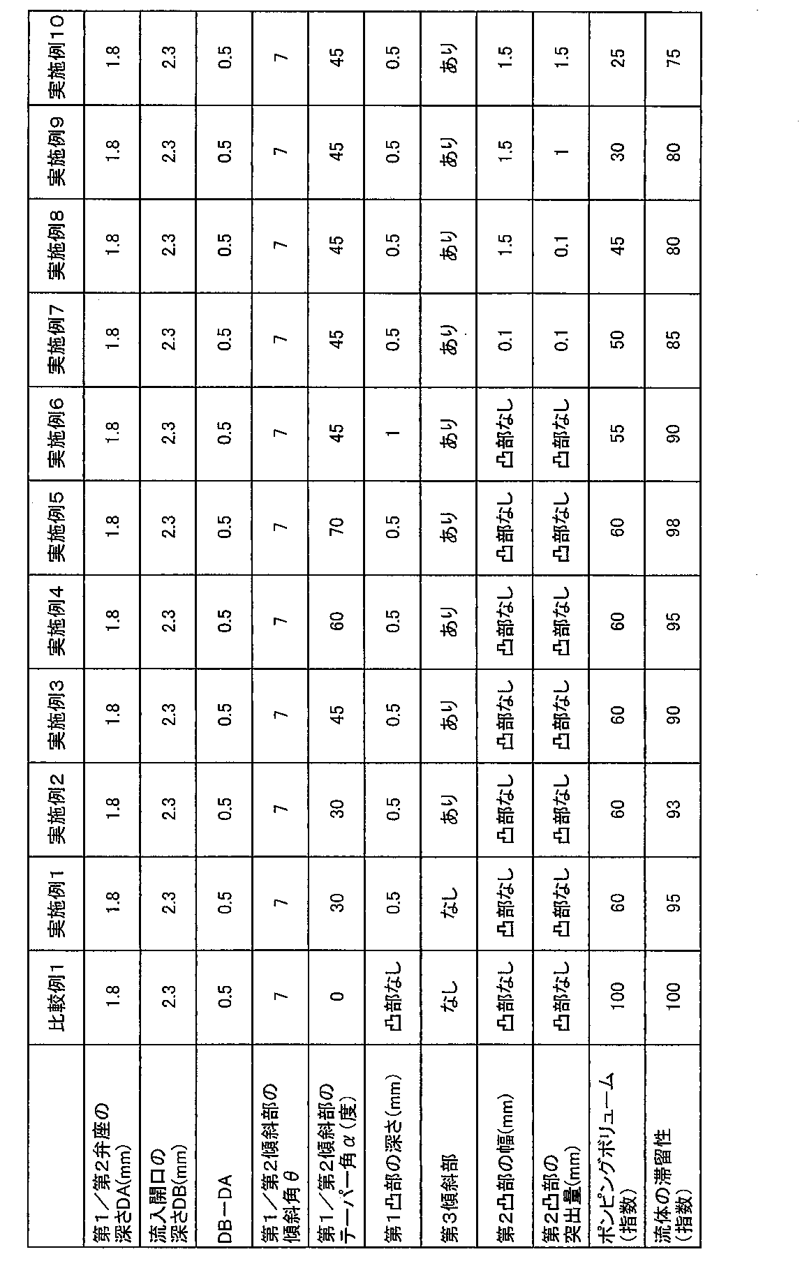
- the valve device with the basic structure shown in Fig. 1 was prototyped based on the specifications in Table 1 and the pumping volume was tested.
- PPS polyphenylene sulfide
- the test method is as follows.
- ⁇ Pumping volume> A channel block of each specification was incorporated into the valve device and the pumping volume was measured. That is, all ports were filled with water, a voltage of 12V was applied to the solenoid coil, and the change in the water level in the tube connected to the outflow port was measured. The value obtained by converting the change in the water level in the tube into the volume in the tube is the pumping volume.
- a universal projector V12-BS made by Nikon) was used for the measurement of the water level.
- a result is an index
- valve device of the example had a significantly smaller pumping volume than that of the comparative example and contributed to the improvement of the operation accuracy.
- Valve device 2 Casing 3 Sub-block (second block) 5 Valve drive (diaphragm drive means) 20 Channel block (first block) 20A Channel block (first block) 21 Valve chamber 22 Recess 23 Inflow port 23a Inflow opening 24 NC outflow port (first outflow port) 24b First valve seat 25 NO outflow port (second outflow port) 25b 2nd valve seat 41 Diaphragm 55 Solenoid coil 51 1st plunger 81 1st inclination part 82 2nd inclination part 83 1st convex part 84 2nd convex part 85 Inflow port 85a Inflow opening 86 Outflow port 86b Valve seat 87 Inclination part
Abstract
Description
図1、2は、本実施形態の弁装置1の断面図である。図1は、後述するソレノイドコイル55への通電を遮断している非通電状態であり、図2は、ソレノイドコイル55に通電している通電状態である。
各仕様の流路ブロックが、弁装置に組み込まれ、ポンピングボリュームが測定された。すなわち、全てのポートが水で満たされ、ソレノイドコイルに12Vの電圧が印加され、流出ポートに接続されたチューブ内の水位の変化が測定された。チューブ内の水位の変化をチューブ内の体積に変換した値がポンピングボリュームである。水位の測定には、万能投影機(V12-BS ニコン製)が用いられた。結果は、比較例1を100とする指数であり、数値が小さい程、ポンピングボリュームが小さく、弁装置の動作精度が優れていることを示す。
各仕様の流路ブロックに相当する解析モデルが作成され、コンピュータシミュレーションによって弁室内の流体の滞留性が計算された。結果は、比較例1を100とする指数であり、数値が小さい程、流体の滞留が抑制されることを示す。
2 ケーシング
3 サブブロック(第2ブロック)
5 弁駆動部(ダイアフラム駆動手段)
20 流路ブロック(第1ブロック)
20A 流路ブロック(第1ブロック)
21 弁室
22 凹部
23 流入ポート
23a 流入開口
24 NC流出ポート(第1流出ポート)
24b 第1弁座
25 NO流出ポート(第2流出ポート)
25b 第2弁座
41 ダイアフラム
55 ソレノイドコイル
51 第1プランジャー
81 第1傾斜部
82 第2傾斜部
83 第1凸部
84 第2凸部
85 流入ポート
85a 流入開口
86 流出ポート
86b 弁座
87 傾斜部
Claims (12)
- ケーシング内に設けられた凹部と、
前記凹部を覆うことにより前記凹部との間に流体が流れる空間である弁室を形成するダイアフラムと、
前記凹部で開口しかつ前記弁室に流体を流入させる流入ポートと、
前記凹部で開口しかつ前記弁室から流体を流出させる流出ポートと、
前記ダイアフラムを揺動させることにより、前記ダイアフラムを、前記流出ポートの開口がなす弁座に密着又は離隔させることにより、前記流出ポートを閉鎖又は開放するダイアフラム駆動手段とを有する弁装置であって、
前記凹部は、前記弁座側から、前記流入ポートが前記弁室へ連通する流入開口に向かって深さが漸増する傾斜部を有し、
前記弁室は、前記流出ポート及び流入ポートが並ぶ縦方向と、前記縦方向及び前記深さ方向と直交する幅方向を有し、
前記流入開口の幅方向の両側に第1凸部が設けられることにより、前記傾斜部は、前記流入開口から前記弁座に向かって幅が漸増しているテーパー状であることを特徴とする弁装置。 - 前記第1凸部は、前記弁室の幅方向の両側から前記流入開口に向かって、前記流入開口を通る平面に対する傾きが漸増する請求項1記載の弁装置。
- 前記流出ポートは、第1流出ポート及び第2流出ポートの2系統が配され、
前記ダイアフラム駆動手段が、前記ダイアフラムを揺動させることにより、前記ダイアフラムを、前記第1流出ポートの開口がなす第1弁座又は前記第2流出ポートの開口がなす第2弁座のいずれか一方に密着させることにより、前記弁室の流体を前記第1流出ポート又は前記第2流出ポートの他方側から流出させ、
前記凹部は、前記第1弁座側から、前記流入ポートが前記弁室へ連通する流入開口に向かって深さが漸増する第1傾斜部と、前記第2弁座側から、前記流入開口に向かって深さが漸増する第2傾斜部とを有し、
前記第1流出ポート、流入ポート及び第2流出ポートは、この順番で配列され、
前記第1傾斜部及び前記第2傾斜部は、前記流入開口から前記第1弁座及び第2弁座に向かって幅が漸増している請求項1又は2に記載の弁装置。 - 前記ダイアフラム側から視た平面視において、前記傾斜部は、30~60度のテーパー角を有している請求項1乃至3記載の弁装置。
- 前記凹部の周縁には、前記ダイアフラムと密着して該ダイアフラムを保持する保持面が形成され、
前記第1凸部の前記保持面からの深さは、0mmより大きい請求項1乃至4に記載の弁装置。 - 前記傾斜部には、前記ダイアフラム側に突出する第2凸部が設けられる請求項1乃至5のいずれかに記載の弁装置。
- 前記流入開口の深さは、前記弁座の深さよりも大きい請求項1乃至6のいずれかに記載の弁装置。
- 前記流入開口の深さと、前記弁座の深さとの差が0.3mm以上である請求項7記載の弁装置。
- 前記弁座は、前記ダイアフラム側に突出する請求項1乃至8のいずれかに記載の弁装置。
- 前記傾斜部は、前記流入開口を通る平面に対して、3度~15度の角度で傾斜している請求項1乃至9のいずれかに記載の弁装置。
- 前記ケーシングは、前記凹部が形成された第1ブロックと、前記第1ブロックに固着されて前記ダイアフラムを保持する第2ブロックとを含み、
前記第1ブロックと前記第2ブロックの合わせ面を基準面としたときに、前記弁座の深さDAは、1.5~2.5mmであり、前記流入開口の深さDBは、2.0~3.0mmである請求項1乃至10のいずれかに記載の弁装置。 - 前記ダイアフラム駆動手段は、コイルと、前記コイルへの通電により前記ダイアフラムに変位を与えるプランジャーとを含む請求項1乃至11のいずれかに記載の弁装置。
Priority Applications (4)
| Application Number | Priority Date | Filing Date | Title |
|---|---|---|---|
| EP14865560.8A EP3076054B1 (en) | 2013-11-26 | 2014-10-01 | Valve device |
| CN201480060470.5A CN105723135B (zh) | 2013-11-26 | 2014-10-01 | 阀装置 |
| US15/039,297 US9802198B2 (en) | 2013-11-26 | 2014-10-01 | Valve device |
| KR1020167014883A KR102241053B1 (ko) | 2013-11-26 | 2014-10-01 | 밸브 장치 |
Applications Claiming Priority (2)
| Application Number | Priority Date | Filing Date | Title |
|---|---|---|---|
| JP2013244197A JP6228439B2 (ja) | 2013-11-26 | 2013-11-26 | 弁装置 |
| JP2013-244197 | 2013-11-26 |
Publications (1)
| Publication Number | Publication Date |
|---|---|
| WO2015079800A1 true WO2015079800A1 (ja) | 2015-06-04 |
Family
ID=53198754
Family Applications (1)
| Application Number | Title | Priority Date | Filing Date |
|---|---|---|---|
| PCT/JP2014/076312 WO2015079800A1 (ja) | 2013-11-26 | 2014-10-01 | 弁装置 |
Country Status (6)
| Country | Link |
|---|---|
| US (1) | US9802198B2 (ja) |
| EP (1) | EP3076054B1 (ja) |
| JP (1) | JP6228439B2 (ja) |
| KR (1) | KR102241053B1 (ja) |
| CN (1) | CN105723135B (ja) |
| WO (1) | WO2015079800A1 (ja) |
Families Citing this family (6)
| Publication number | Priority date | Publication date | Assignee | Title |
|---|---|---|---|---|
| DE102014114212A1 (de) * | 2014-09-30 | 2016-03-31 | Bürkert Werke GmbH | Membranventil |
| DE102015219197B4 (de) * | 2015-10-05 | 2019-07-04 | Conti Temic Microelectronic Gmbh | Pneumatisches Magnetventil |
| CN106286887A (zh) * | 2016-10-10 | 2017-01-04 | 深圳市晶感科技开发有限公司 | 一种电磁阀用密封组件及带有该密封组件的电磁阀 |
| WO2019151499A1 (ja) * | 2018-02-01 | 2019-08-08 | 積水化学工業株式会社 | ダイヤフラムバルブ |
| EP3572698A1 (en) * | 2018-05-21 | 2019-11-27 | Fas Medic S.A. | Rocker valve with rocker valve mechanism |
| CN116951131A (zh) * | 2023-09-20 | 2023-10-27 | 深圳市恒永达科技股份有限公司 | 医疗仪器液路开关电磁阀及控制方法 |
Citations (7)
| Publication number | Priority date | Publication date | Assignee | Title |
|---|---|---|---|---|
| DE2123914A1 (de) * | 1971-05-14 | 1972-11-23 | Siemens-Electrogeräte GmbH, 1000 Berlin u. 8000 München | Mehrwegehahn, insbesondere Mischventil |
| JPH06207678A (ja) * | 1992-03-18 | 1994-07-26 | Automatic Switch Co | ロッカ弁部材および隔離ダイアフラムを有する弁 |
| JP2002502486A (ja) * | 1997-06-05 | 2002-01-22 | ガンブロ ルンデイア アクチーボラグ | 二方向弁 |
| JP2004144243A (ja) * | 2002-10-25 | 2004-05-20 | Ckd Corp | 小型電磁弁 |
| JP2005163924A (ja) * | 2003-12-03 | 2005-06-23 | Ckd Corp | 小型電磁弁とその弁部構造 |
| JP4252512B2 (ja) | 2004-08-17 | 2009-04-08 | シーケーディ株式会社 | 小型電磁弁 |
| DE102012005122A1 (de) * | 2012-03-14 | 2013-09-19 | Festo Ag & Co. Kg | Membranventil |
Family Cites Families (18)
| Publication number | Priority date | Publication date | Assignee | Title |
|---|---|---|---|---|
| FR2609518B1 (fr) * | 1987-01-12 | 1990-12-28 | Abx Sa | Microelectrovanne de commutation a une seule membrane |
| IE61313B1 (en) * | 1988-06-30 | 1994-10-19 | Abx Sa | Switching microelectrovalve having a single diaphragm |
| DE4222594A1 (de) * | 1992-07-09 | 1994-01-13 | Roemer J C Avs Gmbh | Ventil |
| EP0780611A1 (en) * | 1995-12-22 | 1997-06-25 | Applied Materials, Inc. | Flow control valve |
| DE19718408A1 (de) * | 1997-04-30 | 1998-11-05 | Nass Magnet Gmbh | Mehrwegeventil |
| US6003552A (en) * | 1998-07-13 | 1999-12-21 | Automatic Switch Company | Rocker valve for sealing large orifices |
| DE19854620C2 (de) * | 1998-11-26 | 2001-05-17 | Festo Ag & Co | Ventileinrichtung, insbesondere Verstärker |
| DE29901855U1 (de) * | 1999-02-03 | 1999-04-08 | Buerkert Werke Gmbh & Co | Fluidisches Steuerelement |
| JP4247566B2 (ja) * | 1999-04-14 | 2009-04-02 | Smc株式会社 | バルブ |
| DE20100471U1 (de) * | 2001-01-11 | 2001-03-15 | Buerkert Werke Gmbh & Co | Mikroventil |
| JP4178050B2 (ja) * | 2003-01-31 | 2008-11-12 | シーケーディ株式会社 | 小型電磁弁 |
| US7070162B2 (en) * | 2003-07-18 | 2006-07-04 | South Bend Controls, Inc. | Valve actuating apparatus |
| CN101101069B (zh) * | 2006-07-04 | 2010-12-22 | 深圳迈瑞生物医疗电子股份有限公司 | 微型阀 |
| US8752584B2 (en) * | 2006-10-12 | 2014-06-17 | Fluid Automation Systems S.A. | Rocker valve mechanism and rocker valve |
| DE202009016447U1 (de) * | 2009-12-03 | 2010-03-11 | Bürkert Werke GmbH | Fluidisches Steuerelement |
| DE102009058164A1 (de) * | 2009-12-15 | 2011-06-16 | Svm Schultz Verwaltungs-Gmbh & Co. Kg | Ventil mit einem Betätigungsglied |
| DE102012007766A1 (de) * | 2012-04-20 | 2013-10-24 | Bürkert Werke GmbH | Verfahren und Herstellung von Ventilen, Ventile sowie Ventilserie |
| DE102014114212A1 (de) * | 2014-09-30 | 2016-03-31 | Bürkert Werke GmbH | Membranventil |
-
2013
- 2013-11-26 JP JP2013244197A patent/JP6228439B2/ja active Active
-
2014
- 2014-10-01 US US15/039,297 patent/US9802198B2/en active Active
- 2014-10-01 EP EP14865560.8A patent/EP3076054B1/en active Active
- 2014-10-01 KR KR1020167014883A patent/KR102241053B1/ko active IP Right Grant
- 2014-10-01 WO PCT/JP2014/076312 patent/WO2015079800A1/ja active Application Filing
- 2014-10-01 CN CN201480060470.5A patent/CN105723135B/zh active Active
Patent Citations (7)
| Publication number | Priority date | Publication date | Assignee | Title |
|---|---|---|---|---|
| DE2123914A1 (de) * | 1971-05-14 | 1972-11-23 | Siemens-Electrogeräte GmbH, 1000 Berlin u. 8000 München | Mehrwegehahn, insbesondere Mischventil |
| JPH06207678A (ja) * | 1992-03-18 | 1994-07-26 | Automatic Switch Co | ロッカ弁部材および隔離ダイアフラムを有する弁 |
| JP2002502486A (ja) * | 1997-06-05 | 2002-01-22 | ガンブロ ルンデイア アクチーボラグ | 二方向弁 |
| JP2004144243A (ja) * | 2002-10-25 | 2004-05-20 | Ckd Corp | 小型電磁弁 |
| JP2005163924A (ja) * | 2003-12-03 | 2005-06-23 | Ckd Corp | 小型電磁弁とその弁部構造 |
| JP4252512B2 (ja) | 2004-08-17 | 2009-04-08 | シーケーディ株式会社 | 小型電磁弁 |
| DE102012005122A1 (de) * | 2012-03-14 | 2013-09-19 | Festo Ag & Co. Kg | Membranventil |
Also Published As
| Publication number | Publication date |
|---|---|
| JP2015102196A (ja) | 2015-06-04 |
| US9802198B2 (en) | 2017-10-31 |
| CN105723135B (zh) | 2019-05-17 |
| EP3076054B1 (en) | 2018-12-12 |
| EP3076054A4 (en) | 2017-08-09 |
| KR102241053B1 (ko) | 2021-04-16 |
| KR20160089389A (ko) | 2016-07-27 |
| CN105723135A (zh) | 2016-06-29 |
| JP6228439B2 (ja) | 2017-11-08 |
| US20160367990A1 (en) | 2016-12-22 |
| EP3076054A1 (en) | 2016-10-05 |
Similar Documents
| Publication | Publication Date | Title |
|---|---|---|
| WO2015079800A1 (ja) | 弁装置 | |
| JP6228450B2 (ja) | 弁装置 | |
| JP6212463B2 (ja) | 小型電磁弁 | |
| JP2015059597A (ja) | 電磁弁 | |
| JPS63298416A (ja) | 圧力調整弁 | |
| TWI748176B (zh) | 電磁閥 | |
| US9482360B2 (en) | Miniature high performance solenoid valve | |
| JP4265965B2 (ja) | 小型電磁弁の製造方法 | |
| JP6014072B2 (ja) | ダイアフラムの固定構造、それを備えたダイアフラムポンプ及び弁装置 | |
| JP4252512B2 (ja) | 小型電磁弁 | |
| JP4712645B2 (ja) | スライド式ソレノイドバルブ | |
| JP2009257438A (ja) | ダイアフラムバルブ | |
| CN112984194A (zh) | 电磁阀以及电磁阀的制作方法 | |
| CN220204825U (zh) | 一种动态电磁阀 | |
| JP3932898B2 (ja) | 電磁弁装置 | |
| JP2004144151A (ja) | 流路切換弁 | |
| JP7090449B2 (ja) | パイロット式電磁弁 | |
| JP2017015113A (ja) | 弁装置及びそれに用いられるガスケット | |
| JP2009002383A (ja) | スライド式ソレノイドバルブ | |
| KR20200091806A (ko) | 전자 밸브 | |
| JP2019007584A (ja) | 流路切換弁 | |
| JP2020051330A (ja) | 電磁ポンプ | |
| JP2011247249A (ja) | 容積型ポンプ | |
| JP2019019899A (ja) | 電磁弁 | |
| JP2006207493A (ja) | 斜軸式可変容量型ポンプ・モータ |
Legal Events
| Date | Code | Title | Description |
|---|---|---|---|
| 121 | Ep: the epo has been informed by wipo that ep was designated in this application |
Ref document number: 14865560 Country of ref document: EP Kind code of ref document: A1 |
|
| WWE | Wipo information: entry into national phase |
Ref document number: 15039297 Country of ref document: US |
|
| NENP | Non-entry into the national phase |
Ref country code: DE |
|
| ENP | Entry into the national phase |
Ref document number: 20167014883 Country of ref document: KR Kind code of ref document: A |
|
| REEP | Request for entry into the european phase |
Ref document number: 2014865560 Country of ref document: EP |
|
| WWE | Wipo information: entry into national phase |
Ref document number: 2014865560 Country of ref document: EP |