WO2015079653A1 - 熱交換器 - Google Patents
熱交換器 Download PDFInfo
- Publication number
- WO2015079653A1 WO2015079653A1 PCT/JP2014/005793 JP2014005793W WO2015079653A1 WO 2015079653 A1 WO2015079653 A1 WO 2015079653A1 JP 2014005793 W JP2014005793 W JP 2014005793W WO 2015079653 A1 WO2015079653 A1 WO 2015079653A1
- Authority
- WO
- WIPO (PCT)
- Prior art keywords
- tubes
- tube
- core plate
- width direction
- heat exchanger
- Prior art date
Links
Images


Classifications
-
- F—MECHANICAL ENGINEERING; LIGHTING; HEATING; WEAPONS; BLASTING
- F28—HEAT EXCHANGE IN GENERAL
- F28F—DETAILS OF HEAT-EXCHANGE AND HEAT-TRANSFER APPARATUS, OF GENERAL APPLICATION
- F28F9/00—Casings; Header boxes; Auxiliary supports for elements; Auxiliary members within casings
- F28F9/02—Header boxes; End plates
- F28F9/0219—Arrangements for sealing end plates into casing or header box; Header box sub-elements
- F28F9/0224—Header boxes formed by sealing end plates into covers
- F28F9/0226—Header boxes formed by sealing end plates into covers with resilient gaskets
-
- F—MECHANICAL ENGINEERING; LIGHTING; HEATING; WEAPONS; BLASTING
- F28—HEAT EXCHANGE IN GENERAL
- F28D—HEAT-EXCHANGE APPARATUS, NOT PROVIDED FOR IN ANOTHER SUBCLASS, IN WHICH THE HEAT-EXCHANGE MEDIA DO NOT COME INTO DIRECT CONTACT
- F28D1/00—Heat-exchange apparatus having stationary conduit assemblies for one heat-exchange medium only, the media being in contact with different sides of the conduit wall, in which the other heat-exchange medium is a large body of fluid, e.g. domestic or motor car radiators
- F28D1/02—Heat-exchange apparatus having stationary conduit assemblies for one heat-exchange medium only, the media being in contact with different sides of the conduit wall, in which the other heat-exchange medium is a large body of fluid, e.g. domestic or motor car radiators with heat-exchange conduits immersed in the body of fluid
- F28D1/04—Heat-exchange apparatus having stationary conduit assemblies for one heat-exchange medium only, the media being in contact with different sides of the conduit wall, in which the other heat-exchange medium is a large body of fluid, e.g. domestic or motor car radiators with heat-exchange conduits immersed in the body of fluid with tubular conduits
- F28D1/053—Heat-exchange apparatus having stationary conduit assemblies for one heat-exchange medium only, the media being in contact with different sides of the conduit wall, in which the other heat-exchange medium is a large body of fluid, e.g. domestic or motor car radiators with heat-exchange conduits immersed in the body of fluid with tubular conduits the conduits being straight
- F28D1/0535—Heat-exchange apparatus having stationary conduit assemblies for one heat-exchange medium only, the media being in contact with different sides of the conduit wall, in which the other heat-exchange medium is a large body of fluid, e.g. domestic or motor car radiators with heat-exchange conduits immersed in the body of fluid with tubular conduits the conduits being straight the conduits having a non-circular cross-section
- F28D1/05366—Assemblies of conduits connected to common headers, e.g. core type radiators
- F28D1/05383—Assemblies of conduits connected to common headers, e.g. core type radiators with multiple rows of conduits or with multi-channel conduits
-
- F—MECHANICAL ENGINEERING; LIGHTING; HEATING; WEAPONS; BLASTING
- F28—HEAT EXCHANGE IN GENERAL
- F28F—DETAILS OF HEAT-EXCHANGE AND HEAT-TRANSFER APPARATUS, OF GENERAL APPLICATION
- F28F9/00—Casings; Header boxes; Auxiliary supports for elements; Auxiliary members within casings
- F28F9/02—Header boxes; End plates
- F28F9/04—Arrangements for sealing elements into header boxes or end plates
- F28F9/16—Arrangements for sealing elements into header boxes or end plates by permanent joints, e.g. by rolling
- F28F9/18—Arrangements for sealing elements into header boxes or end plates by permanent joints, e.g. by rolling by welding
- F28F9/182—Arrangements for sealing elements into header boxes or end plates by permanent joints, e.g. by rolling by welding the heat-exchange conduits having ends with a particular shape, e.g. deformed; the heat-exchange conduits or end plates having supplementary joining means, e.g. abutments
-
- F—MECHANICAL ENGINEERING; LIGHTING; HEATING; WEAPONS; BLASTING
- F28—HEAT EXCHANGE IN GENERAL
- F28D—HEAT-EXCHANGE APPARATUS, NOT PROVIDED FOR IN ANOTHER SUBCLASS, IN WHICH THE HEAT-EXCHANGE MEDIA DO NOT COME INTO DIRECT CONTACT
- F28D1/00—Heat-exchange apparatus having stationary conduit assemblies for one heat-exchange medium only, the media being in contact with different sides of the conduit wall, in which the other heat-exchange medium is a large body of fluid, e.g. domestic or motor car radiators
- F28D1/02—Heat-exchange apparatus having stationary conduit assemblies for one heat-exchange medium only, the media being in contact with different sides of the conduit wall, in which the other heat-exchange medium is a large body of fluid, e.g. domestic or motor car radiators with heat-exchange conduits immersed in the body of fluid
- F28D1/04—Heat-exchange apparatus having stationary conduit assemblies for one heat-exchange medium only, the media being in contact with different sides of the conduit wall, in which the other heat-exchange medium is a large body of fluid, e.g. domestic or motor car radiators with heat-exchange conduits immersed in the body of fluid with tubular conduits
- F28D1/053—Heat-exchange apparatus having stationary conduit assemblies for one heat-exchange medium only, the media being in contact with different sides of the conduit wall, in which the other heat-exchange medium is a large body of fluid, e.g. domestic or motor car radiators with heat-exchange conduits immersed in the body of fluid with tubular conduits the conduits being straight
- F28D1/0535—Heat-exchange apparatus having stationary conduit assemblies for one heat-exchange medium only, the media being in contact with different sides of the conduit wall, in which the other heat-exchange medium is a large body of fluid, e.g. domestic or motor car radiators with heat-exchange conduits immersed in the body of fluid with tubular conduits the conduits being straight the conduits having a non-circular cross-section
- F28D1/05366—Assemblies of conduits connected to common headers, e.g. core type radiators
-
- F—MECHANICAL ENGINEERING; LIGHTING; HEATING; WEAPONS; BLASTING
- F28—HEAT EXCHANGE IN GENERAL
- F28F—DETAILS OF HEAT-EXCHANGE AND HEAT-TRANSFER APPARATUS, OF GENERAL APPLICATION
- F28F2225/00—Reinforcing means
- F28F2225/08—Reinforcing means for header boxes
-
- F—MECHANICAL ENGINEERING; LIGHTING; HEATING; WEAPONS; BLASTING
- F28—HEAT EXCHANGE IN GENERAL
- F28F—DETAILS OF HEAT-EXCHANGE AND HEAT-TRANSFER APPARATUS, OF GENERAL APPLICATION
- F28F2275/00—Fastening; Joining
- F28F2275/12—Fastening; Joining by methods involving deformation of the elements
- F28F2275/122—Fastening; Joining by methods involving deformation of the elements by crimping, caulking or clinching
-
- F—MECHANICAL ENGINEERING; LIGHTING; HEATING; WEAPONS; BLASTING
- F28—HEAT EXCHANGE IN GENERAL
- F28F—DETAILS OF HEAT-EXCHANGE AND HEAT-TRANSFER APPARATUS, OF GENERAL APPLICATION
- F28F2280/00—Mounting arrangements; Arrangements for facilitating assembling or disassembling of heat exchanger parts
- F28F2280/04—Means for preventing wrong assembling of parts
Definitions
- This disclosure relates to a heat exchanger.
- a header tank of a heat exchanger such as a radiator is configured by integrating a metal core plate to which tubes are joined and a resin tank main body portion that forms a space in the tank.
- a packing made of an elastic member such as rubber is disposed between the core plate and the tank main body. The core plate and the tank are compressed by compressing the packing between the core plate and the tank main body. The main body is sealed.
- the core plate has a tube joint surface to which the tube is joined, and a groove formed at the outer peripheral edge of the tube joint surface.
- the tip portion on the core plate side of the tank main body portion is inserted.
- the tank body is fixed by caulking to the core plate in a state where the packing is sandwiched between the groove of the core plate and the tip of the tank body.
- the length in the flow direction of the external fluid (air) in the core plate is increased by the amount of the groove.
- the length of the flow direction of the air as the whole heat exchanger may become long.
- the length in the air flow direction may be referred to as the width direction dimension.
- a heat exchanger in which the width is reduced by eliminating the groove portion of the core plate is disclosed (for example, see Patent Document 1).
- the packing is directly arranged on the tube joining surface of the core plate to be joined in a state where the tube is inserted.
- the end of the tank body is positioned on the packing.
- the tank body is fixed by caulking to the core plate in a state where the packing is sandwiched between the tube joint surface of the core plate and the tip of the tank body.
- This indication aims at providing the heat exchanger which can make the dimension of the width direction small, suppressing the position shift of a sealing member in view of the above-mentioned point.
- the heat exchanger according to the first aspect of the present disclosure is arranged side by side, and a plurality of tubes in which a fluid flows and a plurality of tubes are arranged at end portions in the longitudinal direction of the plurality of tubes.
- a header tank extending in the direction and communicating with the plurality of tubes.
- the header tank has a core plate to which a plurality of tubes are joined, and a tank body portion fixed to the core plate.
- the tank body is fixed by caulking to the core plate.
- the core plate has a tube joint surface, a seal surface on which an elastically deformable seal member is disposed, and an inclined surface that connects between the tube joint surface and the seal surface.
- the inclined surface is inclined with respect to the longitudinal direction, the longitudinal distance between the tube joining surface and the longitudinal end surfaces of the plurality of tubes is different from the longitudinal distance between the sealing surface and the end surface. ing.
- the plurality of tubes are bonded to the tube bonding surface and the inclined surface in a state of being inserted into the tube bonding surface and at least a part of the inclined surface.
- the distance between the end surfaces in the longitudinal direction of the plurality of tubes and the tube joining surface is a distance between the end surfaces in the longitudinal direction of the plurality of tubes and the sealing surface. It may be shorter.
- the distance between the tube joining surface and the end surfaces in the longitudinal direction of the plurality of tubes and the distance between the seal surface and the end surfaces are different from each other, so that the positional deviation of the seal member can be suppressed.
- the dimension of the tube joint surface in the width direction can be reduced by joining the tube to the tube joint surface and the inclined surface in a state where the tube is inserted into the tube joint surface and the inclined surface. For this reason, the dimension of the width direction of a header tank can be made small. Therefore, it is possible to reduce the size of the heat exchanger in the width direction while suppressing the displacement of the seal member.
- FIG. 4 is a sectional view taken along line IV-IV in FIG. 3.
- FIG. 5 is a VV cross-sectional view of FIG. 3.
- FIG. 6 is a sectional view taken along line VI-VI in FIG. 2. It is the elements on larger scale which looked at the core plate in 2nd Embodiment from the longitudinal direction.
- FIG. 8 is a sectional view taken along line VIII-VIII in FIG. It is a partial expanded sectional view which shows the state before burring part formation of the core plate in 2nd Embodiment.
- FIG. 13 is a sectional view taken along line XIII-XIII in FIG. 12. It is a partial expansion perspective view which shows the tank main-body part in 3rd Embodiment. It is explanatory drawing which shows the junction part vicinity of the core plate and tube in 3rd Embodiment.
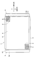
- the radiator 1 of the present embodiment includes a core portion 4 composed of a plurality of tubes 2 and fins 3, and a pair of header tanks 5 that are assembled and arranged at both ends of the core portion 4. Yes.
- Tube 2 is a tube through which fluid flows.
- the fluid refers to engine cooling water.
- the tube 2 is formed in a flat shape so that the fluid flow direction coincides with the longitudinal direction.
- the plurality of tubes 2 are arranged in parallel to each other in a direction (parallel arrangement direction) perpendicular to the longitudinal direction so that the longitudinal direction thereof coincides with the horizontal direction.
- the direction in which the plurality of tubes 2 are arranged is referred to as a juxtaposed direction.
- the fin 3 is formed into a wave shape and joined to the flat surfaces on both sides of the tube 2.
- the fins 3 increase the heat transfer area with the air and promote heat exchange between the engine cooling water flowing through the tube 2 and the air.
- the header tank 5 extends in the juxtaposed direction at both longitudinal ends of the tube 2 and communicates with the plurality of tubes 2. In the present embodiment, one header tank 5 is disposed at each end of the tube 2 in the longitudinal direction.
- the header tank 5 includes a core plate 51 that is joined in a state where the tube 2 is inserted, and a tank body portion 52 that constitutes a tank space together with the core plate 51.
- side plates 6 that reinforce the core portion 4 are provided at both ends in the parallel arrangement direction of the core portions 4.
- the side plate 6 extends in the longitudinal direction, and both end portions thereof are connected to the header tank 5.
- a direction orthogonal to both the longitudinal direction and the juxtaposed direction of the tubes 2 is referred to as a width direction.
- the width direction is parallel to the air flow direction.
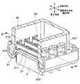
- header tank 5 Next, the detailed configuration of the header tank 5 will be described with reference to FIGS.
- illustration of the packing 53 mentioned later is abbreviate
- the header tank 5 has a core plate 51, a tank body 52, and a packing 53 (see FIG. 6).
- the core plate 51 is joined in a state where the tube 2 and the side plate 6 are inserted.
- the tank body 52 forms a space in the header tank 5 together with the core plate 51.
- the packing 53 is a seal member that seals between the core plate 51 and the tank main body 52.
- the core plate 51 is made of an aluminum alloy
- the tank body 52 is made of a resin such as glass-reinforced polyamide reinforced with glass fibers.
- the packing 53 of this embodiment is formed of rubber that can be elastically deformed. More specifically, the packing 53 of this embodiment is made of ethylene-propylene-diene rubber (EPDM).
- EPDM ethylene-propylene-diene rubber
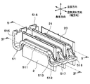
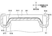
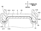
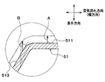
- the core plate 51 includes a tube joining surface 511, a seal surface 512 on which the packing 53 is disposed, and an inclination connecting the tube joining surface 511 and the seal surface 512.
- the tube joint surface 511 and the seal surface 512 are parallel to each other. Specifically, the tube joint surface 511 and the seal surface 512 are perpendicular to the longitudinal direction.
- the inclined surface 513 is inclined with respect to each of the tube joint surface 511 and the seal surface 512.
- the inclined surface 513 is inclined with respect to the longitudinal direction.
- the angle formed by the seal surface 512 and the inclined surface 513 and the angle formed by the tube joint surface 511 and the inclined surface 513 are obtuse angles.
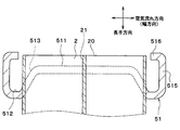
- the tube 2 has a longitudinal end face (tube end face) 20. Since the inclined surface 513 is inclined with respect to the longitudinal direction, the distance in the longitudinal direction between the tube end surface 20 and the tube joining surface 511 is different from the distance in the longitudinal direction between the tube end surface 20 and the seal surface 512. Yes. In this embodiment, the distance in the longitudinal direction between the tube joining surface 511 and the tube end surface 20 is shorter than the distance in the longitudinal direction between the seal surface 512 and the tube end surface 20. That is, the seal surface 512 is located on the inner side in the longitudinal direction of the tube 2 (side closer to the core portion 4) than the tube joint surface 511.
- a large number of tube insertion holes (not shown) into which the tube 2 is inserted and brazed are formed in the tube joining surface 511 and the inclined surface 513 along the parallel direction.
- the tube 2 is bonded to the tube bonding surface 511 and the inclined surface 513 in a state where the tube 2 is inserted into the tube bonding surface 511 and the inclined surface 513 through the tube insertion hole.
- the tube 2 may be inserted into the tube joint surface 511 and at least a part of the inclined surface 513.
- side tube insertion holes (not shown) into which the side plate 6 is inserted and brazed are formed in the tube joint surface 511 and the inclined surface 513 in the juxtaposed direction of the tube joint surface 511 and the inclined surface 513, respectively. One is formed at each end.
- the side plate 6 is joined to the tube joining surface 511 and the inclined surface 513 in a state of being inserted into the tube joining surface 511 and the inclined surface 513 through the side plate insertion hole.
- the core plate 51 has an outer wall portion 515 that is bent at a substantially right angle from the seal surface 512 toward the opposite side of the core portion 4 and extends in the juxtaposition direction or the air flow direction.
- a rib 518 having a surface parallel to the longitudinal direction is provided between the adjacent tubes 2 on the inclined surface 513 of the core plate 51.
- a plane parallel to the longitudinal direction having the ribs 518 is hereinafter referred to as a parallel plane 517.
- the parallel surface 517 is perpendicular to the air flow direction.
- the angle formed between the parallel surface 517 and the seal surface 512 is substantially a right angle.
- the rib 518 is formed so as to protrude outward from the header tank 5.
- the length of the tank body 52 in the air flow direction is shorter than the length of the tube 2 in the air flow direction.
- a bulging portion 521 that bulges toward the outer side of the tank is formed at a portion of the tank main body 52 that faces the tube 2. Thereby, it is comprised so that the inner surface of the tank main-body part 52 and the outer surface of the tube 2 may not contact.
- the end on the core plate 51 side is thicker than the other portions.
- a flange portion 522 is provided. The flange portion 522 is disposed on the seal surface 512 of the core plate 51 via the packing 53.
- the core plate 51 is provided with a plurality of caulking claw portions 516.
- the caulking claw portions 516 protrude from the outer wall portion 515 toward the tank main body portion 52.
- the caulking claw portion 516 is located at a portion corresponding to the space between adjacent tubes 2 in the core plate 51, that is, a portion corresponding to the flange portion 522 of the tank main body portion 52. Then, as shown in FIG. 6, the tank body 52 is fixed to the core plate 51 by crimping the caulking claw 516 to the flange 522 of the tank body 52.
- an inner column portion 21 is provided inside the tube 2 so as to connect the two flat surfaces and increase the pressure resistance of the tube 2.
- the inner column part 21 is located in the center part in the air flow direction inside the tube 2.
- the inner pillar 21 divides the fluid passage inside the tube 2 into two.
- the tube joining surface 511 and the seal surface 512 are provided on the core plate 51.
- the longitudinal distance between the tube joining surface 511 and the tube end surface 20 is different from the longitudinal distance between the seal surface 512 and the tube end surface 20. That is, in the present embodiment, in the core plate 51, the surface (tube bonding surface 511) on which the tube 2 is inserted and bonded and the surface (sealing surface 512) on which the packing 53 is disposed are located on the same plane. Not done. Further, when the core plate 51 and the tank body 52 are crimped, the header tank 5 abuts on the core plate inclined surface 513 and is held. Thereby, interference with the tube 2 can be prevented.
- the packing 53 comes into contact with the inclined surface 513, so that the displacement of the packing 53 can be suppressed.
- the seal surface 512 between the inclined surface 513 and the outer wall portion 515 the positional deviation of the packing 53 can be more reliably suppressed.
- the tube 2 is inserted and joined to both the tube joining surface 511 and the inclined surface 513.
- the dimension of the width direction of the tube joint surface 511 becomes small, and the dimension of the width direction of the header tank 5 can be made small.
- the size in the width direction of the radiator 1 can be reduced.
- the flange portion 522 of the tank main body portion 52 is located on the tube joint surface 511 of the core plate 51.
- the flange part 522 may contact
- the tank main body 52 and the core plate 51 are caulked, the tank 2 may be damaged by the tank main body 52 being deformed toward the inner side of the tank.
- the core plate 51 has ribs 518 having parallel surfaces 517 parallel to the longitudinal direction at portions corresponding to between the adjacent tubes 2 on the inclined surface 513.
- the flange 522 of the tank body 52 abuts against the parallel surfaces 517 of the ribs 518 in the core plate 51. For this reason, it can suppress that the flange part 522 contact
- the tank body 52 and the core plate 51 are fixed by caulking with the flange 522 of the tank body 52 in contact with the parallel surfaces 517 of the ribs 518 in the core plate 51. The For this reason, when the tank main-body part 52 and the core plate 51 are crimped, it can suppress that the tank main-body part 52 deform
- the radiator 1 of the present embodiment it is possible to reliably prevent the tube 2 from being damaged.
- ribs 518 having parallel surfaces 517 parallel to the longitudinal direction are provided at portions corresponding to between the adjacent tubes 2 on the inclined surface 513 of the core plate 51, so that the tank main body portion 52 is provided on the parallel surface 517.
- the flange portion 522 comes into contact. For this reason, when the flange part 522 is arranged on the core plate 51 and when the tank main body part 52 and the core plate 51 are caulked, the tank main body part 52 can be securely held.
- many tube insertion holes 519 into which the tube 2 is inserted and brazed are formed in the tube joint surface 511 and the inclined surface 513 of the core plate 51 along the parallel arrangement direction.
- the tube insertion hole 519 only needs to be formed in the tube joint surface 511 and at least a part of the inclined surface 513, and the tube insertion hole 519 does not necessarily have to be formed over the entire inclined surface 513.
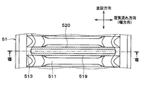
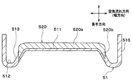
- a burring portion 520 that protrudes toward the end face 20 (see FIG. 11) in the longitudinal direction is provided at the edge of the tube insertion hole 519.
- the burring portion 520 is connected to both the tube joint surface 511 and the inclined surface 513 in the core plate 51.
- the burring portion 520 is formed by performing burring on the edge of the tube insertion hole 519.
- first burring portion (first portion) 520a a portion of the burring portion 520 that is connected to the tube joint surface 511, that is, a portion facing the tube joint surface 511 is referred to as a first burring portion (first portion) 520a.
- second burring portion (second portion) 520b a portion of the burring portion 520 that is connected to the inclined surface 513, that is, a portion facing the inclined surface 513 is referred to as a second burring portion (second portion) 520b.
- the first burring portion 520a and the second burring portion 520b are integrally formed.
- the burring forming direction (see arrow A in FIG. 9) of the first burring portion 520a is perpendicular to the tube joint surface 511.
- the burring forming direction (see arrow B in FIG. 9) of the second burring portion 520b is an acute angle with respect to the inclined surface 513. For this reason, the length Lb in the longitudinal direction of the second burring portion 520b is longer than the length La in the longitudinal direction of the first burring portion 520a.
- the burring portion 520 that protrudes toward the end face 20 in the longitudinal direction is provided at the edge of the tube insertion hole 519. According to this, since the strength of the joint portion between the core plate 51 and the tube 2 can be improved, the heat distortion resistance (resistance to heat distortion) can be improved.
- the joint portion C between the inclined surface 513 and the outer end 22 in the width direction (air flow direction) of the tube 2 is the largest. Thermal distortion occurs.
- the joint portion C is also referred to as a maximum thermal strain generation portion C.
- the length Lb in the longitudinal direction of the second burring portion 520b connected to the inclined surface 513 is the length in the longitudinal direction of the first burring portion 520a connected to the tube joining surface 511.
- the length is longer than La.
- ribs 530 projecting in the longitudinal direction are provided between the adjacent tubes 2 on the inclined surface 513 of the core plate 51.
- the outer end portion 530 a in the width direction (air flow direction) of the rib 530 is located outside the outer end portion 22 in the width direction of the tube 2 in the width direction. That is, the rib 530 is provided so as to straddle the outer end 22 of the tube 2 in the width direction when viewed from the juxtaposed direction. In other words, the rib 530 is provided so as to extend from the inner side to the outer side in the width direction of the outer end portion 22 of the tube 2.
- the inner end portion 512 a in the width direction of the seal surface 512 of the core plate 51 is positioned on the outer side in the width direction with respect to the outer end portion 22 of the tube 2.
- the inner end portion 512 a of the seal surface 512 in the width direction is located on the outer side in the width direction with respect to the outer end portion 530 a of the rib 530.
- the rib 530 has the outer end portion 530a in the width direction, and the tube 2 is in the width direction.
- the outer end portion 530 a of the rib 530 is located on the outer side in the width direction with respect to the outer end portion 22 of the tube 2.
- the outer end 22 of the tubes 2, the outer end 530a of the rib 530, and the inner end 512a of the seal surface 512 are directed from the inner side to the outer side in the width direction. They are located in this order.
- the outer end portion 530a of the rib 530 is located on the outer side in the longitudinal direction (the outer side of the core portion 4) with respect to the inner end portion 512a of the seal surface 512. Therefore, a step 540 is formed between the inclined surface 513 and the seal surface 512 in the core plate 51.
- the outer end portion 530 a of the rib 530 is located on the inner side in the width direction than the step 540.
- the tank main body 52 has corrugated portions 525 having a plurality of inner ridge portions 523 and a plurality of inner valley portions 524 arranged alternately on the inner surface.
- the waved portion 525 is provided on a surface substantially orthogonal to the width direction on the inner surface of the tank main body 52.
- the inner ridge portion 523 of the wavy portion 525 is located between the adjacent tubes 2.
- the distance between one inner ridge portion of the plurality of inner ridge portions 523 and the other inner ridge portion facing the one inner ridge portion in the width direction is greater than the length in the width direction of the tube 2. Also short. That is, the inner width of the tank body 52 defined by the inner ridge 523 is shorter than the length of the tube 2 in the width direction.
- the inner width of the tank main body 52 is the length in the width direction in the tank main body 52.
- the inner valley portion 524 of the wave-like portion 525 is located outside the tube 2 in the width direction.
- the outer end 22 in the width direction of the tube 2 is housed inside the inner valley 524. That is, the outer end 22 in the width direction of the tube 2 is located inside the inner valley portion 524.
- the inner surface of the inner valley portion 524 is formed in a curved surface shape (circular arc shape).
- the outer end portion 530 a of the rib 530 is located on the outer side in the width direction with respect to the outer end portion 22 of the tube 2. According to this, the intensity
- the inner end portion 512a of the seal surface 512 is located on the outer side in the width direction with respect to the outer end portion 530a of the rib 530. According to this, as shown in FIG. 15, when thermal distortion occurs, the core plate 51 is easily bent with the inner end portion 512a of the seal surface 512 as a base point. For this reason, the thermal strain can be absorbed by deforming the core plate 51.
- a step 540 is formed between the inclined surface 513 and the seal surface 512 in the core plate 51, and the outer end 530 a of the rib 530 is positioned on the inner side in the width direction than the step 540.
- the strength of the inner end portion 512a of the seal surface 512 is improved by the rib 530. For this reason, when thermal distortion occurs, it is difficult to bend the core plate 51 with the inner end portion 512a of the seal surface 512 as a base point.
- the inner surface of the inner valley part 524 is formed in a curved surface shape. For this reason, it can suppress that stress concentrates on the inner valley part 524, and can improve the pressure
- FIG. 5 by providing the inner valley portion 524 on the inner surface of the tank main body portion 52, it is not necessary to provide the bulging portion 521 corresponding to the inner valley portion 534 on the outer surface of the tank main body portion 52. Thereby, since the outer surface of the tank main-body part 52 can be formed flatly, the design freedom of the caulking claw part 516 of the core plate 51 can be improved.
- the present disclosure is not limited to the above-described embodiment, and can be variously modified as follows without departing from the spirit of the present disclosure. The technical features disclosed in each of the above embodiments may be combined as appropriate within a feasible range.
- the angle formed by the seal surface 512 and the inclined surface 513 is an obtuse angle, but for example, the angle formed by the seal surface 512 and the inclined surface 513 may be a right angle. That is, the inclined surface 513 may be perpendicular to the seal surface 512.
- the heat exchanger of the present disclosure can also be applied to other heat exchangers such as an evaporator and a refrigerant radiator (refrigerant condenser).
- the packing 53 is configured separately from the core plate 51 and the tank main body 52 .
- the structure of the packing 53 is not limited to this.
- the packing 53 may be joined or integrally molded to either one of the core plate 51 and the tank body 52 with an adhesive or the like.
- the fixing structure by caulking of the core plate 51 is not limited to this.
- the cut formed in a part of the outer wall portion 515 of the core plate 51 is plastically deformed in the air flow direction and engaged with the unevenness formed in the flange portion 522 of the tank main body portion 52, so that the core plate 51 and the tank The main body 52 may be fixed by caulking.
Landscapes
- Engineering & Computer Science (AREA)
- Physics & Mathematics (AREA)
- Thermal Sciences (AREA)
- Mechanical Engineering (AREA)
- General Engineering & Computer Science (AREA)
- Heat-Exchange Devices With Radiators And Conduit Assemblies (AREA)
- Air-Conditioning For Vehicles (AREA)
Abstract
熱交換器は、複数のチューブ(2)と、複数のチューブ(2)の長手方向の端部に位置し、複数のチューブ(2)に連通するヘッダタンク(5)とを備える。ヘッダタンク(5)は、複数のチューブ(2)が接合されるコアプレート(51)と、コアプレート(51)に固定されるタンク本体部(52)とを有する。コアプレート(51)は、チューブ接合面(511)と、シール面(512)と、チューブ接合面(511)とシール面(515)との間を接続する傾斜面(513)とを有する。傾斜面(513)が長手方向に対して傾斜することで、チューブ接合面(511)と、複数のチューブ(2)の長手方向の端面(20)との間の距離が、シール面(512)と前記端面(20)との間の距離と異なっている。複数のチューブ(2)は、チューブ接合面(511)および傾斜面(513)に挿入された状態でチューブ接合面(511)および傾斜面(513)に接合されている。
Description
本出願は、当該開示内容が参照によって本出願に組み込まれた、2013年11月27日に出願された日本特許出願2013-244749号および2014年9月3日に出願された日本特許出願2014-179461号を基にしている。
本開示は、熱交換器に関するものである。
従来、ラジエータ等の熱交換器のヘッダタンクは、各チューブが接合された金属製のコアプレートと、タンク内の空間を形成する樹脂製のタンク本体部とを一体化することによって構成されている。コアプレートとタンク本体部との間には、ゴム等の弾性部材からなるパッキン(シール部材)が配置されており、このパッキンをコアプレートおよびタンク本体部にて圧縮することで、コアプレートとタンク本体部とをシールしている。
具体的には、コアプレートは、チューブが接合されるチューブ接合面と、チューブ接合面の外周縁部に形成された溝部とを有している。コアプレートの溝部には、タンク本体部のうちコアプレート側の先端部が挿入されている。コアプレートの溝部とタンク本体部の先端部との間にパッキンが挟まれた状態で、タンク本体部がコアプレートにカシメることで固定されている。
このような熱交換器では、コアプレートに溝部を形成している。従って、この溝部の分だけ、コアプレートにおける外部流体(空気)の流れ方向の長さが長くなる。これにより、熱交換器全体としての空気の流れ方向の長さが長くなるおそれがある。なお、以下では、空気の流れ方向の長さを、幅方向の寸法と称する場合がある。
これに対し、コアプレートの溝部を廃止することで薄幅化を図った熱交換器が開示されている(例えば、特許文献1参照)。具体的には、特許文献1に記載の熱交換器では、チューブが挿入された状態で接合される、コアプレートのチューブ接合面上に直接パッキンが配置されている。このパッキン上にタンク本体部の端部が位置している。そして、コアプレートのチューブ接合面とタンク本体部の先端部との間にパッキンが挟まれた状態で、タンク本体部がコアプレートにカシメることで固定されている。
しかしながら、本願発明者らの検討によると上記特許文献1に記載の熱交換器では、パッキンが、コアプレートのチューブ接合面上に直接配置される。これにより、コアプレートとタンク本体部とをカシメることで固定した時にパッキンの位置ズレが発生するおそれがある。
本開示は上記点に鑑みて、シール部材の位置ズレを抑制しつつ、幅方向の寸法を小さくすることができる熱交換器を提供することを目的とする。
本開示の第1態様に係る熱交換器は、互いに並んで配置されるとともに、内部に流体が流通する複数のチューブと、複数のチューブの長手方向の端部に位置し、複数のチューブが並ぶ方向に延びて複数のチューブに連通するヘッダタンクとを備える。ヘッダタンクは、複数のチューブが接合されるコアプレートと、コアプレートに固定されるタンク本体部とを有する。タンク本体部は、コアプレートにカシメることで固定されている。コアプレートは、チューブ接合面と、弾性変形可能なシール部材が配置されるシール面と、チューブ接合面とシール面との間を接続する傾斜面とを有している。傾斜面が長手方向に対して傾斜することで、チューブ接合面と複数のチューブの長手方向の端面との間の長手方向の距離が、シール面と当該端面との間の長手方向の距離と異なっている。複数のチューブは、チューブ接合面と、傾斜面の少なくとも一部とに挿入された状態で、チューブ接合面および傾斜面に接合されている。
あるいは、本開示の第2態様に係る熱交換器は、複数のチューブの長手方向の端面とチューブ接合面との間の距離が、複数のチューブの長手方向の端面とシール面との間の距離よりも短くなっていてもよい。
チューブ接合面と複数のチューブの長手方向の端面との間の距離と、シール面と当該端面との間の距離が互いに異なることで、シール部材の位置ズレを抑制できる。
また、チューブを、チューブ接合面および傾斜面に挿入した状態でチューブ接合面および傾斜面に接合することで、チューブ接合面の幅方向の寸法を小さくすることができる。このため、ヘッダタンクの幅方向の寸法を小さくすることができる。したがって、シール部材の位置ズレを抑制しつつ、熱交換器の幅方向の寸法を小さくすることが可能となる。
以下、本開示の実施形態について図に基づいて説明する。なお、以下の各実施形態相互において、互いに同一もしくは均等である部分には、図中、同一符号を付してある。
(第1実施形態)
本開示の第1実施形態について図面に基づいて説明する。本実施形態では、本開示に係る熱交換器を、エンジン冷却水と空気との間で熱交換を行いエンジン冷却水を冷却する自動車用ラジエータに適用した場合を例として説明する。
(第1実施形態)
本開示の第1実施形態について図面に基づいて説明する。本実施形態では、本開示に係る熱交換器を、エンジン冷却水と空気との間で熱交換を行いエンジン冷却水を冷却する自動車用ラジエータに適用した場合を例として説明する。
図1に示すように、本実施形態のラジエータ1は、複数のチューブ2およびフィン3からなるコア部4と、コア部4の両端部に組み付け配置される一対のヘッダタンク5とを有している。
チューブ2は流体が流れる管である。本実施形態において、流体とはエンジン冷却水を指す。このチューブ2は、流体の流れ方向が長手方向と一致するように扁平状に形成されている。さらに、複数のチューブ2は、その長手方向が水平方向に一致するように、長手方向と垂直な方向(並設方向)に互いに平行に並んで配置されている。以下の説明では、複数のチューブ2が並ぶ方向を並設方向と称する。
フィン3は、波状に成形されるとともに、チューブ2の両側の扁平面に接合されている。このフィン3により、空気との伝熱面積を増大させてチューブ2内を流通するエンジン冷却水と空気との熱交換を促進している。
ヘッダタンク5は、チューブ2の長手方向の両端部にて並設方向に延びて複数のチューブ2と連通するものである。本実施形態では、ヘッダタンク5は、チューブ2の長手方向の両端部に1つずつ配置されている。このヘッダタンク5は、チューブ2が挿入された状態で接合されるコアプレート51と、コアプレート51とともにタンク空間を構成するタンク本体部52とを有する。
また、コア部4の並設方向における両端部には、コア部4を補強するサイドプレート6が設けられている。サイドプレート6は、長手方向に延びてその両端部がヘッダタンク5に接続されている。
以下、ラジエータ1において、チューブ2の長手方向および並設方向の双方に直交する方向を幅方向という。幅方向は、空気流れ方向と平行になっている。
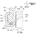
次に、ヘッダタンク5の詳細な構成を、図2~図6に基づいて説明する。なお、図2では、後述するパッキン53の図示を省略している。
図2に示すように、ヘッダタンク5は、コアプレート51と、タンク本体部52と、パッキン53(図6参照)とを有している。コアプレート51には、チューブ2およびサイドプレート6が挿入された状態で接合される。タンク本体部52は、コアプレート51と共にヘッダタンク5内の空間を構成する。パッキン53は、コアプレート51とタンク本体部52との間をシールするシール部材である。本実施形態では、コアプレート51をアルミニウム合金製とし、タンク本体部52をガラス繊維で強化されたガラス強化ポリアミド等の樹脂製としている。
そして、パッキン53がコアプレート51とタンク本体部52との間に挟まれた状態で、コアプレート51の後述するカシメ用爪部516をタンク本体部52に押し付けるように塑性変形させてタンク本体部52をコアプレート51にカシメることで固定している。本実施形態のパッキン53は、弾性変形可能なゴムにより形成されている。より具体的には、本実施形態のパッキン53は、エチレン-プロピレン-ジエンゴム(EPDM)により形成されている。
図3、図4および図5に示すように、コアプレート51は、チューブ接合面511と、パッキン53が配置されるシール面512と、チューブ接合面511とシール面512との間を接続する傾斜面513とを有している。本実施形態では、チューブ接合面511およびシール面512は、互いに平行になっている。具体的には、チューブ接合面511およびシール面512は、長手方向に対して垂直になっている。
本実施形態では、傾斜面513は、チューブ接合面511およびシール面512のそれぞれに対して傾斜している。換言すれば、傾斜面513は長手方向に対して傾斜している。具体的には、シール面512と傾斜面513との成す角、および、チューブ接合面511と傾斜面513との成す角は、それぞれ鈍角になっている。
図6に示すように、チューブ2は、長手方向の端面(チューブ端面)20を有する。傾斜面513が長手方向に対して傾斜することで、チューブ端面20とチューブ接合面511との間の長手方向の距離が、チューブ端面20とシール面512との間の長手方向の距離と異なっている。本実施形態では、チューブ接合面511とチューブ端面20との間の長手方向の距離が、シール面512とチューブ端面20との間の長手方向の距離よりも短くなっている。すなわち、シール面512は、チューブ接合面511よりも、チューブ2の長手方向の内側(コア部4に近い側)に位置している。
チューブ接合面511および傾斜面513には、チューブ2が挿入されてろう付けされるチューブ挿入穴(図示せず)が並設方向に沿って多数形成されている。チューブ2は、チューブ接合面511および傾斜面513にチューブ挿入穴を介して挿入された状態で、チューブ接合面511および傾斜面513に接合されている。チューブ2は、チューブ接合面511と、傾斜面513の少なくとも一部とに挿入されていればよい。
また、チューブ接合面511および傾斜面513には、サイドプレート6が挿入されてろう付けされるサイドプレート挿入穴(図示せず)が、チューブ接合面511および傾斜面513のそれぞれにおける並設方向の両端側に1つずつ形成されている。そして、サイドプレート6は、チューブ接合面511および傾斜面513にサイドプレート挿入穴を介して挿入された状態でチューブ接合面511および傾斜面513に接合されている。
コアプレート51は、シール面512からコア部4と反対側に向かって略直角に折り曲げられるとともに、並設方向または空気流れ方向に延びる外側壁部515を有している。
コアプレート51の傾斜面513における隣り合うチューブ2の間には、長手方向に平行な面を有するリブ518が設けられている。リブ518を有する長手方向に平行な面を、以下、平行面517という。本実施形態では、平行面517は、空気流れ方向に対して垂直になっている。また、平行面517とシール面512との成す角度が略直角になっている。また、リブ518は、ヘッダタンク5の外方に突出するように形成されている。
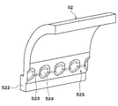
図2に示すように、タンク本体部52の空気流れ方向の長さは、チューブ2の空気流れ方向の長さよりも短くなっている。タンク本体部52におけるチューブ2と対向する部位には、タンク外方側に向けて膨らんだ膨出部521が形成されている。これにより、タンク本体部52の内面とチューブ2の外面とが接触しないように構成されている。
タンク本体部52における隣り合うチューブ2同士の間に対向する部位、すなわち膨出部521が形成されていない部位には、コアプレート51側の端部が他の部位よりも板厚が厚くなっているフランジ部522が設けられている。フランジ部522は、コアプレート51のシール面512にパッキン53を介して配置されている。
ところで、コアプレート51には、カシメ用爪部516が複数設けられている。カシメ用爪部516は、外側壁部515からタンク本体部52に向けて突出している。また、カシメ用爪部516は、コアプレート51における隣り合うチューブ2同士の間に対応する部位、すなわちタンク本体部52のフランジ部522に対応する部位に位置している。そして、図6に示すように、カシメ用爪部516をタンク本体部52のフランジ部522にカシメることで、タンク本体部52はコアプレート51に固定されている。
なお、図2および図3に示すように、チューブ2の内部には、二つの扁平面同士を接続するように形成され、チューブ2の耐圧強度を高める内柱部21が設けられている。本実施形態では、内柱部21は、チューブ2内部における空気流れ方向の中央部に位置している。この内柱部21により、チューブ2内部の流体通路が二つに仕切られている。
以上説明したように、本実施形態では、コアプレート51にチューブ接合面511とシール面512とを設けている。チューブ接合面511とチューブ端面20との間の長手方向の距離は、シール面512とチューブ端面20との間の長手方向の距離と異なる。すなわち、本実施形態では、コアプレート51において、チューブ2が挿入されるとともに接合される面(チューブ接合面511)と、パッキン53が配置される面(シール面512)とが同一平面上に位置していない。また、コアプレート51とタンク本体部52とをカシメた時には、ヘッダタンク5がコアプレート傾斜面513に当接し、保持される。これにより、チューブ2への干渉を防止することができる。
また、コアプレート51とタンク本体部52とをカシメた時にパッキン53は傾斜面513と当接するため、パッキン53の位置ズレを抑制できる。具体的には、シール面512を、傾斜面513と外側壁部515との間に形成することで、パッキン53の位置ズレをより確実に抑制できる。
また、本実施形態では、チューブ2を、チューブ接合面511および傾斜面513の両方に挿入されるとともに接合している。これにより、チューブ接合面511の幅方向の寸法が小さくなり、ヘッダタンク5の幅方向の寸法を小さくすることができる。その結果、ラジエータ1の幅方向の寸法を小さくすることが可能となる。
ところで、上記特許文献1に記載の熱交換器では、コアプレート51のチューブ接合面511上にタンク本体部52のフランジ部522が位置している。このため、ヘッダタンク5の製造工程において、タンク本体部52をコアプレート51上に配置する際に、フランジ部522がチューブ2に当接し、チューブ2が損傷するおそれがある。また、タンク本体部52とコアプレート51とをカシメる際に、タンク本体部52がタンクの内方側に向かって変形することで、チューブ2が損傷するおそれもある。
これに対し、本実施形態では、コアプレート51は、傾斜面513における隣り合うチューブ2同士の間と対応する部位に、長手方向に平行な平行面517を有するリブ518を有している。これにより、タンク本体部52をコアプレート51に組み付けた際に、タンク本体部52のフランジ部522が、コアプレート51におけるリブ518の平行面517と当接する。このため、フランジ部522がチューブ2に当接することを抑制できる。
また、本実施形態では、タンク本体部52のフランジ部522が、コアプレート51におけるリブ518の平行面517と当接した状態で、タンク本体部52とコアプレート51とがカシメることで固定される。このため、タンク本体部52とコアプレート51とをカシメた時に、タンク本体部52がタンク内方側に向かって変形することを抑制できる。
したがって、本実施形態のラジエータ1では、チューブ2が損傷することを確実に抑制することが可能となる。
また、コアプレート51の傾斜面513における隣り合うチューブ2同士の間と対応する部位に、長手方向に平行な平行面517を有するリブ518を設けることで、当該平行面517にタンク本体部52のフランジ部522が当接することになる。このため、コアプレート51にフランジ部522を配置する際、および、タンク本体部52とコアプレート51とをカシメる際に、タンク本体部52を確実に保持することが可能となる。
(第2実施形態)
次に、本開示の第2実施形態について図面に基づいて説明する。本第2実施形態は、上記第1実施形態と比較して、コアプレート51のチューブ挿入穴近傍の構成が異なる。
(第2実施形態)
次に、本開示の第2実施形態について図面に基づいて説明する。本第2実施形態は、上記第1実施形態と比較して、コアプレート51のチューブ挿入穴近傍の構成が異なる。
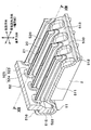
図7に示すように、コアプレート51のチューブ接合面511および傾斜面513には、チューブ2が挿入されてろう付けされるチューブ挿入穴519が並設方向に沿って多数形成されている。チューブ挿入孔519は、チューブ接合面511と、傾斜面513の少なくとも一部とに形成されていれば良く、必ずしも傾斜面513の全体に亘ってチューブ挿入孔519が形成されている必要はない。
図7および図8に示すように、チューブ挿入穴519の縁部には、長手方向の端面20(図11参照)側に向けて突出するバーリング部520が設けられている。バーリング部520は、コアプレート51におけるチューブ接合面511および傾斜面513の双方に接続されている。なお、バーリング部520は、チューブ挿入穴519の縁部にバーリング加工を施すことにより形成されている。
以下、バーリング部520のうち、チューブ接合面511に接続される、すなわちチューブ接合面511と対向する部位を、第1バーリング部(第1の部位)520aという。また、バーリング部520のうち、傾斜面513に接続される、すなわち傾斜面513と対向する部位を、第2バーリング部(第2の部位)520bという。第1バーリング部520aおよび第2バーリング部520bは、一体に形成されている。
図9に示すように、チューブ接合面511において、第1バーリング部520aのバーリング成形方向(図9中の矢印A参照)は、チューブ接合面511に対して垂直になっている。また、傾斜面513において、第2バーリング部520bのバーリング成形方向(図9中の矢印B参照)は、傾斜面513に対して鋭角になっている。このため、第2バーリング部520bにおける長手方向の長さLbは、第1バーリング部520aにおける長手方向の長さLaよりも長い。
以上説明したように、本実施形態では、チューブ挿入穴519の縁部に、長手方向の端面20に向けて突出するバーリング部520を設けている。これによれば、コアプレート51とチューブ2との接合部の強度を向上させることができるので、耐熱歪み性(熱歪みに対する耐性)を向上させることが可能となる。
ところで、図11に示すように、コアプレート51とチューブ2との接合部のうち、傾斜面513とチューブ2の幅方向(空気流れ方向)の外側端部22との接合部Cに、最も大きい熱歪みが発生する。以下、当該接合部Cを、最大熱歪み発生部Cともいう。
これに対し、本実施形態では、傾斜面513に接続されている第2バーリング部520bにおける長手方向の長さLbを、チューブ接合面511に接続されている第1バーリング部520aにおける長手方向の長さLaよりも長くしている。これによれば、最大熱歪み発生部Cに対応する第2バーリング部520bの長手方向の長さを長くしているので、最大熱歪み発生部Cの耐熱歪み性を確実に向上させることが可能となる。
(第3実施形態)
次に、本開示の第3実施形態について図面に基づいて説明する。本第3実施形態は、上記第1実施形態と比較して、コアプレート51およびタンク本体部52の構成が異なるものである。
(第3実施形態)
次に、本開示の第3実施形態について図面に基づいて説明する。本第3実施形態は、上記第1実施形態と比較して、コアプレート51およびタンク本体部52の構成が異なるものである。
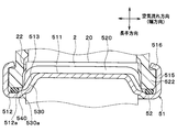
図12および図13に示すように、コアプレート51の傾斜面513における隣り合うチューブ2同士の間には、長手方向に突出するリブ530が設けられている。リブ530における幅方向(空気流れ方向)の外側端部530aは、チューブ2における幅方向の外側端部22よりも、幅方向の外側に位置している。すなわち、リブ530は、並設方向から見たときに、幅方向におけるチューブ2の外側端部22を跨ぐように設けられている。換言すると、リブ530は、チューブ2の外側端部22の幅方向の内側から外側にわたって延びるように設けられている。
図13に示すように、コアプレート51のシール面512における幅方向の内側端部512aは、チューブ2の外側端部22に対して、幅方向の外側に位置している。本実施形態では、幅方向におけるシール面512の内側端部512aは、リブ530における外側端部530aに対して、幅方向の外側に位置している。換言すれば、チューブ2の長手方向および長手方向と垂直な並設方向の双方に直交する方向を幅方向としたとき、リブ530は幅方向において外側端部530aを有し、チューブ2は幅方向において外側端部22を有する。そして、リブ530の外側端部530aは、チューブ2の外側端部22に対して、幅方向の外側に位置している。
このため、チューブ2を並設方向から見たときに、チューブ2の外側端部22、リブ530の外側端部530aおよびシール面512の内側端部512aは、幅方向の内側から外側に向かってこの順に位置している。
また、本実施形態では、リブ530の外側端部530aは、シール面512の内側端部512aよりも、長手方向の外方側(コア部4の外方側)に位置している。このため、コアプレート51において、傾斜面513とシール面512との間には、段差540が形成されている。リブ530の外側端部530aは、段差540よりも幅方向の内側に位置している。
図12および図14に示すように、タンク本体部52は、交互に配置された複数の内峰部523と複数の内谷部524とを有する波状部525を内面に有している。波状部525は、タンク本体部52の内面における幅方向に略直交する面に設けられている。
波状部525の内峰部523は、隣り合うチューブ2の間に位置している。また、複数の内峰部523のうちの一つの内峰部と、当該一つの内峰部と幅方向において対向する他の内峰部との間の距離は、チューブ2の幅方向の長さよりも短い。すなわち、内峰部523が規定するタンク本体部52の内幅はチューブ2の幅方向の長さよりも短い。タンク本体部52の内幅とは、タンク本体部52内の幅方向の長さである。
波状部525の内谷部524は、チューブ2の幅方向の外側に位置している。また、チューブ2の幅方向の外側端部22は、内谷部524の内側に収容されている。すなわち、内谷部524の内部には、チューブ2の幅方向の外側端部22が位置している。また、内谷部524の内面は、曲面状(断面円弧状)に形成されている。
以上説明したように、本実施形態では、リブ530の外側端部530aは、チューブ2の外側端部22に対して、幅方向の外側に位置している。これによれば、コアプレート51の傾斜面513とチューブ2の幅方向(空気流れ方向)の外側端部22との接合部Cの強度を向上させることができる。このため、コアプレート51とチューブ2との接合部のうち、最大熱歪み発生部Cの耐熱歪み性を確実に向上させることが可能となる。
また、本実施形態では、シール面512の内側端部512aが、リブ530の外側端部530aよりも幅方向の外側に位置している。これによれば、図15に示すように、熱歪みが発生した際に、シール面512の内側端部512aを基点として容易にコアプレート51が曲げられる。このため、熱歪みを、コアプレート51を変形させることにより吸収することが可能となる。
さらに、本実施形態では、コアプレート51における傾斜面513とシール面512との間に段差540を形成するとともに、リブ530の外側端部530aを段差540よりも幅方向の内側に位置している。これによれば、段差540によりコアプレート51に強度差がつくため、熱歪みが発生した際に、当該段差540を曲げ基点として、より積極的にコアプレート51を曲げることができる。
シール面512の内側端部512aが、リブ530の外側端部530aよりも幅方向の内側に位置すると、リブ530によりシール面512の内側端部512aの強度が向上する。このため、熱歪みが発生した際に、シール面512の内側端部512aを基点としてコアプレート51を曲げることが困難となる。
また、本実施形態では、内谷部524の内面を曲面状に形成している。このため、内谷部524に応力が集中することを抑制し、ヘッダタンク5の耐圧性を向上させることができる。そして、内谷部524をタンク本体部52の内面に設けることで、タンク本体部52の外面に、内谷部534に対応する膨出部521を設ける必要がなくなる。これにより、タンク本体部52の外面を平坦状に形成することができるので、コアプレート51のカシメ用爪部516の設計自由度を向上させることができる。
(他の実施形態)
本開示は上述の実施形態に限定されることなく、本開示の趣旨を逸脱しない範囲内で、以下のように種々変形可能である。また、上記各実施形態に開示された技術的特徴は、実施可能な範囲で適宜組み合わせてもよい。
(他の実施形態)
本開示は上述の実施形態に限定されることなく、本開示の趣旨を逸脱しない範囲内で、以下のように種々変形可能である。また、上記各実施形態に開示された技術的特徴は、実施可能な範囲で適宜組み合わせてもよい。
(1)上記実施形態では、シール面512と傾斜面513との成す角を鈍角として例について説明したが、例えば、シール面512と傾斜面513との成す角を直角としてもよい。すなわち、傾斜面513をシール面512に対して垂直としてもよい。
(2)上記実施形態では、チューブ接合面511の全面をシール面512に対して平行にした例について説明した。しかしながら、チューブ接合面511の一部、例えばヘッダタンク5の幅方向において中央となる部位をシール面512に対して平行にしてもよい。
(3)上記実施形態では、ラジエータ1に本開示の熱交換器を適用した例について説明した。しかしながら、蒸発器や冷媒放熱器(冷媒凝縮器)等の他の熱交換器においても本開示の熱交換器の適用が可能である。
(4)上記実施形態では、パッキン53を、コアプレート51およびタンク本体部52に対して別体で構成した例について説明した。しかしながら、パッキン53の構成はこれに限定されない。例えば、パッキン53を、コアプレート51およびタンク本体部52のいずれか一方に、接着剤等で接合もしくは一体成形してもよい。
(5)上記実施形態では、コアプレート51のカシメ用爪部516を折り曲げて、タンク本体部52のフランジ部522にカシメることで固定した例について説明した。しかしながら、コアプレート51のカシメによる固定構造はこれに限定されない。例えば、コアプレート51の外側壁部515の一部に形成した切れ目を空気流れ方向に塑性変形させ、タンク本体部52のフランジ部522に形成した凹凸に係合させることで、コアプレート51とタンク本体部52とをカシメることで固定してもよい。
Claims (14)
- 互いに並んで配置されるとともに、内部に流体が流通する複数のチューブ(2)と、
前記複数のチューブ(2)の長手方向の端部に位置し、前記複数のチューブ(2)が並ぶ方向に延びて前記複数のチューブ(2)に連通するヘッダタンク(5)とを備え、
前記ヘッダタンク(5)は、
前記複数のチューブ(2)が接合されるコアプレート(51)と、
前記コアプレート(51)に固定されるタンク本体部(52)とを有し、
前記タンク本体部(52)は、前記コアプレート(51)にカシメることで固定されており、
前記コアプレート(51)は、
チューブ接合面(511)と、
弾性変形可能なシール部材(53)が配置されるシール面(512)と、
前記チューブ接合面(511)と前記シール面(515)との間を接続する傾斜面(513)とを有しており、
前記傾斜面(513)が前記長手方向に対して傾斜することで、前記チューブ接合面(511)と前記複数のチューブ(2)の長手方向の端面(20)との間の前記長手方向の距離が、前記シール面(512)と前記端面(20)との間の前記長手方向の距離と異なっており、
前記複数のチューブ(2)は、前記チューブ接合面(511)と、前記傾斜面(513)の少なくとも一部とに挿入された状態で、前記チューブ接合面(511)および前記傾斜面(513)に接合されている熱交換器。 - 互いに並んで配置されるとともに、内部に流体が流通する複数のチューブ(2)と、
前記複数のチューブ(2)の長手方向の端部に位置し、前記複数のチューブ(2)が並ぶ方向に延びて前記複数のチューブ(2)に連通するヘッダタンク(5)とを備え、
前記ヘッダタンク(5)は、
前記複数のチューブ(2)が接合されるコアプレート(51)と、
前記コアプレート(51)に固定されるタンク本体部(52)と、
前記コアプレート(51)と前記タンク本体部(52)との間をシールする弾性変形可能なシール部材(53)とを有し、
前記タンク本体部(52)は、前記コアプレート(51)にカシメることで固定されており、
前記コアプレート(51)は、
チューブ接合面(511)と、
前記シール部材(53)が配置されるシール面(512)と、
前記チューブ接合面(511)と前記シール面(512)との間を接続する傾斜面(513)とを有しており、
前記傾斜面(513)が前記長手方向に対して傾斜することで、前記複数のチューブ(2)の長手方向の端面(20)と前記チューブ接合面(511)との間の距離が、前記端面(20)と前記シール面(512)との間の距離よりも短くなっており、
前記複数のチューブ(2)は、前記チューブ接合面(511)と、前記傾斜面(513)の少なくとも一部とに挿入された状態で、前記チューブ接合面(511)および前記傾斜面(513)に接合されている熱交換器。 - 前記コアプレート(51)は、前記傾斜面(513)における隣り合う前記複数のチューブ(2)同士の間と対応する部位に、リブ(518、530)を有している請求項1または2に記載の熱交換器。
- 前記傾斜面(513)は、前記シール面(512)に対して傾斜している請求項1ないし3のいずれか1つに記載の熱交換器。
- 前記チューブ接合面(511)の少なくとも一部が、前記シール面(512)に対して平行になっている請求項1ないし4のいずれか1つに記載の熱交換器。
- 前記チューブ接合面(511)と、前記傾斜面(513)の少なくとも一部とには、前記複数のチューブ(2)が挿入されるチューブ挿入穴(519)が設けられており、
前記チューブ挿入穴(519)の縁部には、前記長手方向の端面(20)に向けて突出するバーリング部(520)が設けられている請求項1ないし5のいずれか1つに記載の熱交換器。 - 前記バーリング部(520)は、前記傾斜面(513)に接続された第1の部位(520b)と、前記チューブ接合面(511)に接続された第2の部位(520a)とを備え、
前記第1の部位(520b)の前記長手方向の長さ(Lb)は、前記第2の部位(520a)の前記長手方向の長さ(La)よりも長くなっている請求項6に記載の熱交換器。 - 前記複数のチューブ(2)の長手方向および前記複数のチューブ(2)が並ぶ方向の双方に直交する方向を幅方向とした場合において、
前記リブ(530)は前記幅方向における外側端部(530a)を有し、
前記チューブ(2)は前記幅方向における外側端部(22)を有し、
前記リブ(530)の外側端部(530a)は、前記複数のチューブ(2)の外側端部(22)に対し、前記幅方向の外側に位置している請求項3に記載の熱交換器。 - 前記シール面(512)の前記幅方向の内側端部(512a)は、前記複数のチューブ(2)の前記幅方向の外側端部(22)に対し、前記幅方向の外側に位置している請求項8に記載の熱交換器。
- 前記シール面(512)の前記幅方向の内側端部(512a)は、前記リブ(530)の前記幅方向の外側端部(530a)に対し、前記幅方向の外側に位置している請求項8または9に記載の熱交換器。
- 前記コアプレート(51)は、前記傾斜面(513)と前記シール面(512)との間に段差(540)を有し、
前記リブ(530)における前記幅方向の外側端部(530a)は、前記段差(540)よりも前記幅方向の内側に位置している請求項8ないし10のいずれか1つに記載の熱交換器。 - 前記タンク本体部(52)は、交互に配置された複数の内峰部(523)と複数の内谷部(524)とを有する波状部(525)を内面に有し、
前記複数の内峰部(523)と前記複数のチューブ(2)とは交互に位置しており、
前記長手方向および前記複数のチューブ(2)が並ぶ方向の双方に直交する方向を幅方向とした場合において、前記複数の内峰部(523)のうちの一つの内峰部と、当該一つの内峰部(523)と前記幅方向において対向する他の内峰部(523)との間の距離は、前記チューブ(2)の前記幅方向の長さよりも短い請求項1ないし11のいずれか1つに記載の熱交換器。 - 前記内谷部(524)は、前記幅方向において前記複数のチューブ(2)の外側に位置しており、
前記複数のチューブ(2)の前記幅方向の外側端部(22)は、前記内谷部(524)の内側に収容されている請求項12に記載の熱交換器。 - 前記内谷部(524)の内面が曲面状である請求項12または13に記載の熱交換器。
Priority Applications (4)
| Application Number | Priority Date | Filing Date | Title |
|---|---|---|---|
| CN201480064670.8A CN105793663B (zh) | 2013-11-27 | 2014-11-19 | 热交换器 |
| US15/039,063 US10317148B2 (en) | 2013-11-27 | 2014-11-19 | Heat exchanger |
| EP14866522.7A EP3076118A4 (en) | 2013-11-27 | 2014-11-19 | Heat exchanger |
| US16/394,297 US11162743B2 (en) | 2013-11-27 | 2019-04-25 | Heat exchanger tank |
Applications Claiming Priority (4)
| Application Number | Priority Date | Filing Date | Title |
|---|---|---|---|
| JP2013-244749 | 2013-11-27 | ||
| JP2013244749 | 2013-11-27 | ||
| JP2014179461A JP6394202B2 (ja) | 2013-11-27 | 2014-09-03 | 熱交換器 |
| JP2014-179461 | 2014-09-03 |
Related Child Applications (2)
| Application Number | Title | Priority Date | Filing Date |
|---|---|---|---|
| US15/039,063 A-371-Of-International US10317148B2 (en) | 2013-11-27 | 2014-11-19 | Heat exchanger |
| US16/394,297 Continuation US11162743B2 (en) | 2013-11-27 | 2019-04-25 | Heat exchanger tank |
Publications (1)
| Publication Number | Publication Date |
|---|---|
| WO2015079653A1 true WO2015079653A1 (ja) | 2015-06-04 |
Family
ID=53198626
Family Applications (1)
| Application Number | Title | Priority Date | Filing Date |
|---|---|---|---|
| PCT/JP2014/005793 WO2015079653A1 (ja) | 2013-11-27 | 2014-11-19 | 熱交換器 |
Country Status (5)
| Country | Link |
|---|---|
| US (2) | US10317148B2 (ja) |
| EP (1) | EP3076118A4 (ja) |
| JP (1) | JP6394202B2 (ja) |
| CN (2) | CN109029053B (ja) |
| WO (1) | WO2015079653A1 (ja) |
Cited By (3)
| Publication number | Priority date | Publication date | Assignee | Title |
|---|---|---|---|---|
| DE102018220142A1 (de) * | 2018-11-23 | 2020-05-28 | Mahle International Gmbh | Sammelrohr für einen Wärmeübertrager |
| US11365937B2 (en) | 2018-11-23 | 2022-06-21 | Mahle International Gmbh | Collector tube for a heat exchanger |
| US11662160B2 (en) | 2018-11-23 | 2023-05-30 | Mahle International Gmbh | Collector tube for a heat exchanger |
Families Citing this family (10)
| Publication number | Priority date | Publication date | Assignee | Title |
|---|---|---|---|---|
| DE112016003219T5 (de) * | 2015-07-17 | 2019-05-09 | Denso Corporation | Wärmetauscher |
| WO2017026210A1 (ja) * | 2015-08-07 | 2017-02-16 | 株式会社デンソー | 熱交換器 |
| JP6547576B2 (ja) * | 2015-10-15 | 2019-07-24 | 株式会社デンソー | 熱交換器 |
| WO2017069280A1 (ja) * | 2015-10-22 | 2017-04-27 | 株式会社ティラド | 熱交換器およびその組立て方法 |
| US10823509B2 (en) * | 2016-04-20 | 2020-11-03 | Denso Corporation | Heat exchanger and manufacturing method thereof |
| JP6449811B2 (ja) * | 2016-06-09 | 2019-01-09 | カルソニックカンセイ株式会社 | 熱交換器 |
| DE102018111556A1 (de) * | 2017-06-22 | 2018-12-27 | Hanon Systems | Wärmeübertrager |
| JP6919472B2 (ja) * | 2017-09-29 | 2021-08-18 | 株式会社デンソー | 熱交換器 |
| CN108180778B (zh) * | 2017-12-28 | 2024-05-10 | 天津市华迪汽车散热器有限公司 | 一种散热器主板和水室的密封结构 |
| DE102018219171A1 (de) | 2018-06-29 | 2020-01-02 | Hanon Systems | Batteriekühler |
Citations (9)
| Publication number | Priority date | Publication date | Assignee | Title |
|---|---|---|---|---|
| JPH0346776U (ja) * | 1989-08-30 | 1991-04-30 | ||
| US5899267A (en) * | 1998-09-14 | 1999-05-04 | General Motors Corporation | Heat exchanger sealed tank and header assembly with gasket displacement prevention |
| US20050039900A1 (en) * | 2003-08-19 | 2005-02-24 | Visteon Global Technologies, Inc. | Header for heat exchanger |
| JP2006189206A (ja) * | 2005-01-06 | 2006-07-20 | Denso Corp | 熱交換器 |
| DE102006019536A1 (de) * | 2006-04-27 | 2007-10-31 | Modine Manufacturing Co., Racine | Sammelkasten für Wärmetauscher |
| JP2008528930A (ja) * | 2005-02-03 | 2008-07-31 | ベール ゲーエムベーハー ウント コー カーゲー | 熱交換器 |
| WO2008151680A1 (de) * | 2007-06-15 | 2008-12-18 | Modine Manufacturing Company | Wärmetauscher |
| WO2011061085A1 (fr) | 2009-11-19 | 2011-05-26 | Valeo Systemes Thermiques | Plaque collectrice, boite collectrice comprenant une telle plaque et echangeur de chaleur equipe d'une telle boite |
| WO2013135541A2 (de) * | 2012-03-10 | 2013-09-19 | Volkswagen Aktiengesellschaft | Wärmetauscher mit einem rohrboden sowie ein hierfür bestimmter rohrboden |
Family Cites Families (48)
| Publication number | Priority date | Publication date | Assignee | Title |
|---|---|---|---|---|
| DE2852408B2 (de) | 1978-12-04 | 1981-10-01 | Süddeutsche Kühlerfabrik Julius Fr. Behr GmbH & Co KG, 7000 Stuttgart | Klemmverbindung |
| US4881594A (en) * | 1989-03-27 | 1989-11-21 | General Motors Corporation | Header plate for pressure vessels, heat exchangers and the like |
| US4997035A (en) * | 1990-04-02 | 1991-03-05 | Blackstone Corporation | Joint crevice corrosion inhibitor |
| US4971145A (en) * | 1990-04-09 | 1990-11-20 | General Motors Corporation | Heat exchanger header |
| JPH04108186A (ja) | 1990-08-25 | 1992-04-09 | Apisu:Kk | 皮革及びその製造方法 |
| JP2514456Y2 (ja) | 1991-02-21 | 1996-10-16 | サンデン株式会社 | 熱交換器 |
| US5195579A (en) * | 1992-07-20 | 1993-03-23 | General Motors Corporation | Integral tab lock and bracket assembly for headered tube condenser |
| DE4442040A1 (de) * | 1994-11-25 | 1996-05-30 | Behr Gmbh & Co | Wärmetauscher mit einem Sammelrohr |
| JP3445905B2 (ja) * | 1995-09-30 | 2003-09-16 | ハラ クリメイト コントロール コーポレイション | 熱交換器およびそれに用いられるヘッダパイプの製造方法 |
| CN1162107A (zh) * | 1995-12-13 | 1997-10-15 | 瓦莱奥热机公司 | 用于热交换器的体积缩小的集流板 |
| FR2742532B1 (fr) * | 1995-12-13 | 1998-01-30 | Valeo Thermique Moteur Sa | Plaque collectrice d'encombrement reduit pour echangeur de chaleur |
| FR2745079B1 (fr) * | 1996-02-20 | 1998-04-10 | Valeo Thermique Moteur Sa | Echangeur de chaleur a boite a fluide brasee, en particulier pour vehicule automobile |
| JP3414171B2 (ja) * | 1996-11-29 | 2003-06-09 | 株式会社デンソー | 熱交換器 |
| US6640887B2 (en) * | 2000-12-20 | 2003-11-04 | Visteon Global Technologies, Inc. | Two piece heat exchanger manifold |
| DE10103176B4 (de) * | 2001-01-22 | 2010-06-02 | Behr Gmbh & Co. Kg | Verfahren zum Einbringen von Flachrohreinsteckschlitzen in ein Sammelrohr |
| JP3675348B2 (ja) * | 2001-03-23 | 2005-07-27 | 株式会社デンソー | 熱交換器 |
| JP2004301455A (ja) * | 2003-03-31 | 2004-10-28 | Calsonic Kansei Corp | 熱交換器用のヘッダタンク |
| CN100541108C (zh) * | 2003-08-01 | 2009-09-16 | 昭和电工株式会社 | 集管箱和具有该集管箱的热交换器 |
| WO2005066568A1 (en) * | 2003-12-19 | 2005-07-21 | Valeo, Inc. | Collar rib for heat exchanger tanks |
| JP2005308366A (ja) * | 2004-04-26 | 2005-11-04 | T Rad Co Ltd | 熱交換器 |
| JP2006162194A (ja) | 2004-12-09 | 2006-06-22 | Denso Corp | 熱交換器 |
| JP2006284107A (ja) * | 2005-04-01 | 2006-10-19 | Denso Corp | 熱交換器 |
| JP5029166B2 (ja) * | 2006-06-29 | 2012-09-19 | 株式会社デンソー | 熱交換器 |
| US7621165B2 (en) * | 2006-06-29 | 2009-11-24 | Wheeling-Corrugating Company | Crimp tool |
| DE102007028792A1 (de) * | 2006-06-29 | 2008-01-31 | Denso Corp., Kariya | Wärmeaustauscher |
| CN100498190C (zh) * | 2006-06-29 | 2009-06-10 | 株式会社电装 | 热交换器 |
| FR2904101B1 (fr) | 2006-07-21 | 2008-09-05 | Valeo Systemes Thermiques | Echangeur de chaleur a collecteur ameliore |
| KR100837814B1 (ko) * | 2006-12-22 | 2008-06-13 | 주식회사 하이닉스반도체 | 반도체 메모리 장치의 데이터 출력 회로 |
| KR20090011216A (ko) * | 2007-07-25 | 2009-02-02 | 삼성전자주식회사 | 공기 필터링 장치 및 그를 구비한 반도체 제조설비의청정시스템 |
| WO2009058395A2 (en) * | 2007-11-01 | 2009-05-07 | Modine Manufacturing Company | Heat exchanger |
| US7921558B2 (en) * | 2008-01-09 | 2011-04-12 | Delphi Technologies, Inc. | Non-cylindrical refrigerant conduit and method of making same |
| FR2927412B1 (fr) | 2008-02-13 | 2012-12-21 | Valeo Systemes Thermiques | Plaque collectrice sans gorge |
| US20090255657A1 (en) * | 2008-04-15 | 2009-10-15 | Denso Corporation | Heat exchanger and method of manufacturing the same |
| JP4600506B2 (ja) * | 2008-04-15 | 2010-12-15 | 株式会社デンソー | 熱交換器の製造方法 |
| JP2011099631A (ja) * | 2009-11-06 | 2011-05-19 | Denso Corp | 熱交換器 |
| DE102011008220A1 (de) * | 2010-01-13 | 2012-01-19 | Denso Corporation | Wärmeaustauscher |
| EP2372289B1 (en) * | 2010-03-31 | 2018-11-14 | Modine Manufacturing Company | Heat exchanger |
| US20110240276A1 (en) * | 2010-04-01 | 2011-10-06 | Delphi Technologies, Inc. | Heat exchanger having an inlet distributor and outlet collector |
| US8536834B2 (en) * | 2010-12-23 | 2013-09-17 | Thermo King Corporation | Mobile environment-controlled unit and method of operating a mobile environment-controlled unit |
| KR20120074846A (ko) * | 2010-12-28 | 2012-07-06 | 한라공조주식회사 | 인터쿨러 |
| JP5541218B2 (ja) * | 2011-04-01 | 2014-07-09 | 株式会社デンソー | 熱交換器 |
| DE102011076225A1 (de) * | 2011-05-20 | 2012-11-22 | Behr Gmbh & Co. Kg | Wärmetauscher |
| DE102012202886A1 (de) * | 2012-02-24 | 2013-08-29 | Behr Gmbh & Co. Kg | Wärmeübertrager |
| JP6337442B2 (ja) * | 2013-10-30 | 2018-06-06 | 株式会社デンソー | 熱交換器 |
| JP2015206507A (ja) * | 2014-04-18 | 2015-11-19 | 株式会社デンソー | 熱交換器 |
| JP6384344B2 (ja) * | 2015-02-05 | 2018-09-05 | 株式会社デンソー | 熱交換器 |
| DE112016003219T5 (de) * | 2015-07-17 | 2019-05-09 | Denso Corporation | Wärmetauscher |
| JP6547576B2 (ja) * | 2015-10-15 | 2019-07-24 | 株式会社デンソー | 熱交換器 |
-
2014
- 2014-09-03 JP JP2014179461A patent/JP6394202B2/ja active Active
- 2014-11-19 EP EP14866522.7A patent/EP3076118A4/en not_active Withdrawn
- 2014-11-19 CN CN201810725261.8A patent/CN109029053B/zh active Active
- 2014-11-19 CN CN201480064670.8A patent/CN105793663B/zh not_active Expired - Fee Related
- 2014-11-19 WO PCT/JP2014/005793 patent/WO2015079653A1/ja active Application Filing
- 2014-11-19 US US15/039,063 patent/US10317148B2/en active Active
-
2019
- 2019-04-25 US US16/394,297 patent/US11162743B2/en active Active
Patent Citations (9)
| Publication number | Priority date | Publication date | Assignee | Title |
|---|---|---|---|---|
| JPH0346776U (ja) * | 1989-08-30 | 1991-04-30 | ||
| US5899267A (en) * | 1998-09-14 | 1999-05-04 | General Motors Corporation | Heat exchanger sealed tank and header assembly with gasket displacement prevention |
| US20050039900A1 (en) * | 2003-08-19 | 2005-02-24 | Visteon Global Technologies, Inc. | Header for heat exchanger |
| JP2006189206A (ja) * | 2005-01-06 | 2006-07-20 | Denso Corp | 熱交換器 |
| JP2008528930A (ja) * | 2005-02-03 | 2008-07-31 | ベール ゲーエムベーハー ウント コー カーゲー | 熱交換器 |
| DE102006019536A1 (de) * | 2006-04-27 | 2007-10-31 | Modine Manufacturing Co., Racine | Sammelkasten für Wärmetauscher |
| WO2008151680A1 (de) * | 2007-06-15 | 2008-12-18 | Modine Manufacturing Company | Wärmetauscher |
| WO2011061085A1 (fr) | 2009-11-19 | 2011-05-26 | Valeo Systemes Thermiques | Plaque collectrice, boite collectrice comprenant une telle plaque et echangeur de chaleur equipe d'une telle boite |
| WO2013135541A2 (de) * | 2012-03-10 | 2013-09-19 | Volkswagen Aktiengesellschaft | Wärmetauscher mit einem rohrboden sowie ein hierfür bestimmter rohrboden |
Non-Patent Citations (1)
| Title |
|---|
| See also references of EP3076118A4 * |
Cited By (4)
| Publication number | Priority date | Publication date | Assignee | Title |
|---|---|---|---|---|
| DE102018220142A1 (de) * | 2018-11-23 | 2020-05-28 | Mahle International Gmbh | Sammelrohr für einen Wärmeübertrager |
| US11143464B2 (en) | 2018-11-23 | 2021-10-12 | Mahle International Gmbh | Collector tube for a heat exchanger |
| US11365937B2 (en) | 2018-11-23 | 2022-06-21 | Mahle International Gmbh | Collector tube for a heat exchanger |
| US11662160B2 (en) | 2018-11-23 | 2023-05-30 | Mahle International Gmbh | Collector tube for a heat exchanger |
Also Published As
| Publication number | Publication date |
|---|---|
| US11162743B2 (en) | 2021-11-02 |
| JP6394202B2 (ja) | 2018-09-26 |
| JP2015127631A (ja) | 2015-07-09 |
| US20190249936A1 (en) | 2019-08-15 |
| US10317148B2 (en) | 2019-06-11 |
| EP3076118A1 (en) | 2016-10-05 |
| CN105793663B (zh) | 2018-08-07 |
| CN109029053A (zh) | 2018-12-18 |
| EP3076118A4 (en) | 2017-08-16 |
| CN105793663A (zh) | 2016-07-20 |
| US20170038163A1 (en) | 2017-02-09 |
| CN109029053B (zh) | 2020-12-15 |
Similar Documents
| Publication | Publication Date | Title |
|---|---|---|
| WO2015079653A1 (ja) | 熱交換器 | |
| US11255609B2 (en) | Heat exchanger | |
| CN108139183B (zh) | 热交换器 | |
| WO2014061216A1 (ja) | 熱交換器 | |
| JP2006189206A (ja) | 熱交換器 | |
| JP2006189205A (ja) | 熱交換器 | |
| US20130220585A1 (en) | Tube for heat exchanger | |
| US20080245513A1 (en) | Tube for heat exchanger and method of manufacturing tube | |
| WO2017013918A1 (ja) | 熱交換器 | |
| WO2015159529A1 (ja) | 熱交換器 | |
| US20060113069A1 (en) | Heat exchanger | |
| JP2019090573A (ja) | 熱交換器およびその製造方法 | |
| JP2009216151A (ja) | シール構造およびそれを用いた熱交換器 | |
| JP2006200862A (ja) | 熱交換器用扁平チューブ | |
| JP2005127676A (ja) | 熱交換器および熱交換の製造方法 | |
| JP2020003089A (ja) | 熱交換チューブ及び熱交換器 | |
| KR100565733B1 (ko) | 열교환기와 그 제조 방법 | |
| JP6106546B2 (ja) | 熱交換装置 | |
| JP6919472B2 (ja) | 熱交換器 | |
| JP2018204919A (ja) | 熱交換チューブ及び熱交換器 | |
| JP2008267693A (ja) | 熱交換器 | |
| JP6992581B2 (ja) | 熱交換器 |
Legal Events
| Date | Code | Title | Description |
|---|---|---|---|
| 121 | Ep: the epo has been informed by wipo that ep was designated in this application |
Ref document number: 14866522 Country of ref document: EP Kind code of ref document: A1 |
|
| REEP | Request for entry into the european phase |
Ref document number: 2014866522 Country of ref document: EP |
|
| WWE | Wipo information: entry into national phase |
Ref document number: 2014866522 Country of ref document: EP |
|
| WWE | Wipo information: entry into national phase |
Ref document number: 15039063 Country of ref document: US |
|
| NENP | Non-entry into the national phase |
Ref country code: DE |