WO2015079646A1 - 転炉操業監視方法及び転炉操業方法 - Google Patents
転炉操業監視方法及び転炉操業方法 Download PDFInfo
- Publication number
- WO2015079646A1 WO2015079646A1 PCT/JP2014/005764 JP2014005764W WO2015079646A1 WO 2015079646 A1 WO2015079646 A1 WO 2015079646A1 JP 2014005764 W JP2014005764 W JP 2014005764W WO 2015079646 A1 WO2015079646 A1 WO 2015079646A1
- Authority
- WO
- WIPO (PCT)
- Prior art keywords
- converter
- frequency
- blowing
- lance
- vibration
- Prior art date
- Legal status (The legal status is an assumption and is not a legal conclusion. Google has not performed a legal analysis and makes no representation as to the accuracy of the status listed.)
- Ceased
Links
Images

Classifications
-
- C—CHEMISTRY; METALLURGY
- C21—METALLURGY OF IRON
- C21C—PROCESSING OF PIG-IRON, e.g. REFINING, MANUFACTURE OF WROUGHT-IRON OR STEEL; TREATMENT IN MOLTEN STATE OF FERROUS ALLOYS
- C21C5/00—Manufacture of carbon-steel, e.g. plain mild steel, medium carbon steel or cast steel or stainless steel
- C21C5/28—Manufacture of steel in the converter
- C21C5/42—Constructional features of converters
- C21C5/46—Details or accessories
- C21C5/4673—Measuring and sampling devices
-
- C—CHEMISTRY; METALLURGY
- C21—METALLURGY OF IRON
- C21C—PROCESSING OF PIG-IRON, e.g. REFINING, MANUFACTURE OF WROUGHT-IRON OR STEEL; TREATMENT IN MOLTEN STATE OF FERROUS ALLOYS
- C21C5/00—Manufacture of carbon-steel, e.g. plain mild steel, medium carbon steel or cast steel or stainless steel
- C21C5/28—Manufacture of steel in the converter
- C21C5/30—Regulating or controlling the blowing
- C21C5/35—Blowing from above and through the bath
-
- C—CHEMISTRY; METALLURGY
- C21—METALLURGY OF IRON
- C21C—PROCESSING OF PIG-IRON, e.g. REFINING, MANUFACTURE OF WROUGHT-IRON OR STEEL; TREATMENT IN MOLTEN STATE OF FERROUS ALLOYS
- C21C5/00—Manufacture of carbon-steel, e.g. plain mild steel, medium carbon steel or cast steel or stainless steel
- C21C5/28—Manufacture of steel in the converter
- C21C5/42—Constructional features of converters
- C21C5/46—Details or accessories
- C21C5/4606—Lances or injectors
-
- F—MECHANICAL ENGINEERING; LIGHTING; HEATING; WEAPONS; BLASTING
- F27—FURNACES; KILNS; OVENS; RETORTS
- F27D—DETAILS OR ACCESSORIES OF FURNACES, KILNS, OVENS OR RETORTS, IN SO FAR AS THEY ARE OF KINDS OCCURRING IN MORE THAN ONE KIND OF FURNACE
- F27D21/00—Arrangement of monitoring devices; Arrangement of safety devices
- F27D21/02—Observation or illuminating devices
-
- F—MECHANICAL ENGINEERING; LIGHTING; HEATING; WEAPONS; BLASTING
- F27—FURNACES; KILNS; OVENS; RETORTS
- F27D—DETAILS OR ACCESSORIES OF FURNACES, KILNS, OVENS OR RETORTS, IN SO FAR AS THEY ARE OF KINDS OCCURRING IN MORE THAN ONE KIND OF FURNACE
- F27D21/00—Arrangement of monitoring devices; Arrangement of safety devices
- F27D21/04—Arrangement of indicators or alarms
Definitions
- the present invention relates to a converter operation for producing molten steel from molten iron by spraying oxidizing gas from a top blowing lance to molten iron pig iron. More specifically, the present invention relates to a converter operation monitoring method and a converter operation method capable of reducing iron content adhering to a furnace port, a furnace wall, and the like and iron spouted out of the furnace as dust.
- the hot metal in the furnace and the molten steel produced from this hot metal are stirred from the refining gas supplied from the top blowing lance or from the bottom blowing tuyere. Fluctuation with working gas. Since the furnace port portion of the smelting reaction vessel is open, the smelting reaction vessel is not damaged by resonance with oscillation. However, as the molten iron or molten steel produced from this molten iron fluctuates, the scattering of molten iron increases, and the increase in dust generation due to the aforementioned bubble burst and the iron content near the furnace mouth and in the furnace wall. May increase adhesion and / or deposition.
- the hot metal is decarburized and changed into molten steel, but it is not only difficult to distinguish between hot metal and molten steel during decarburization but also complicated. . Therefore, in this specification, the molten iron and molten steel are collectively indicated as “molten metal”. When the distinction between hot metal and molten steel is clear, “hot metal” or “molten steel” is displayed.
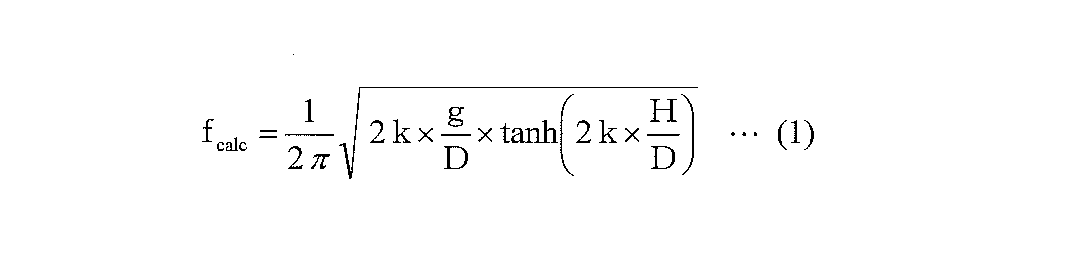
- Non-Patent Document 1 analytically obtains the natural frequency of a cylindrical container such as a converter. According to Non-Patent Document 1, the natural frequency of the cylindrical container is determined based on the inner diameter of the cylindrical container and the bath in the cylindrical container. From the depth (bath depth), it is given by the following equation (1).
- f calc is the natural frequency (Hz)
- g is the gravitational acceleration (9.8 m / s 2 )
- D is the inner diameter (m) of the cylindrical container
- H is the bath depth in the cylindrical container.
- M is a constant having a value of 1.84
- ⁇ is a circumference.
- Non-Patent Document 2 it has been measured that the frequency of the fluctuation of molten iron in a commercial scale converter is about 0.3 to 0.4 Hz. This measured value almost coincides with the natural frequency (f calc ) of the converter calculated from the equation (1).
- the bath surface can be swung due to resonance of the molten iron contained. Therefore, due to this oscillation, the decarburization and refining of hot metal in the converter may increase the origin of dust generation due to bubble burst and increase the adhesion and / or deposition of iron near the furnace wall and furnace mouth. Is extremely high.
- the present invention has been made in view of the above circumstances, and the object of the present invention is to fluctuate the molten iron when performing decarburization and refining of hot metal by blowing an oxidizing gas through an upper blowing lance. It is intended to provide a converter operation monitoring method and a converter operation method capable of suppressing the scattering of molten iron and the reduction of the iron yield caused thereby.
- the gist of the present invention for solving the above problems is as follows.
- Oxidizing gas is blown from the top blowing lance to the hot metal in the converter, or oxidizing gas or inert gas is blown from the bottom blowing tuyere into the hot metal while blowing the oxidizing gas from the top blowing lance.
- a converter operation monitoring method for monitoring vibration frequency of the converter during decarburization refining which is obtained by measuring vibration of the converter and performing frequency analysis of the measured value when decarburizing and refining.
- the oxidizing gas is blown from the top blowing lance to the hot metal in the converter, or the oxidizing gas is blown from the top blowing lance and the oxidizing gas or the inert gas is blown into the hot metal from the bottom blowing tuyere.
- the vibration of the converter is measured, and the frequency of the measured value is analyzed during decarburization and refining, and the frequency of the converter vibration is determined.
- the oxidizing gas blown from the top blowing lance so that the frequency (f obs ) at which the amplitude is maximum becomes larger than the natural frequency (f calc ) of the converter calculated by the following equation (1).
- a converter operation method that adjusts one or both of the flow rate and the lance height of the top blowing lance.
- f calc is the natural frequency (Hz)
- g is the gravitational acceleration (9.8 m / s 2 )
- D is the inner diameter (m) of the hot metal container of the converter
- H is the inside of the converter.
- k is a constant with a value of 1.84
- ⁇ is the circumference.
- the frequency of vibration caused by the fluctuation of molten iron in the converter is monitored in real time during decarburization refining, it is possible to predict whether or not the molten iron is scattered due to fluctuation of the molten iron. .
- the frequency (f obs ) having the maximum amplitude among the vibration frequencies of the converter is supplied from the top blowing lance so that the natural frequency (f calc ) of the converter becomes larger.
- the fluctuation of molten iron in the converter is suppressed and the scattering of molten iron to the outside of the furnace is reduced.
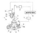
- FIG. 1 is a schematic diagram of converter equipment that can measure the vibration of a converter during decarburization and is suitable for carrying out the present invention.
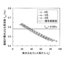
- FIG. 2 is a diagram showing the relationship between the dimensionless lance height (L / d e ) and the frequency (f obs ) having the maximum amplitude among the converter vibration frequencies.
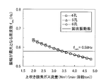
- FIG. 3 is a diagram showing the relationship between the flow rate of the top blown oxygen gas and the frequency (f obs ) at which the amplitude is maximum among the converter vibration frequencies.
- FIG. 4 is a diagram showing the relationship between the average dust generation speed and the frequency (f obs ) at which the amplitude is maximum among the converter vibration frequencies.
- the inventors of the present invention have reported that the amount of dust generated when an oxidizing gas such as oxygen gas is blown over the hot metal in the converter to decarburize and refine the hot metal, and the metal (iron skull) )
- the effect of the flow rate of the oxidizing gas from the top blowing lance and the lance height on the adhesion amount was tested and examined.
- a converter having a capacity of 5 tons capable of blowing an oxidizing gas from the top blowing lance and simultaneously blowing a stirring gas from the bottom blowing tuyeres at the bottom of the furnace is used.
- the test and examination were advanced while measuring Oxygen gas (industrial pure oxygen) was used as the oxidizing gas from the top blowing lance, and argon gas was used as the stirring gas from the bottom blowing tuyere.
- the lance height is the distance from the tip of the top blowing lance to the stationary hot metal bath surface in the converter.
- FIG. 1 is a schematic diagram of converter equipment that can be used to measure vibrations of a converter used in the above test during decarburization and is suitable for carrying out the present invention.
- reference numeral 1 is a converter facility
- 2 is a converter
- 3 is a top blowing lance
- 4 is a bottom blowing tuyere
- 5 is hot metal
- 6 is an accelerometer sensor
- 7 is an accelerometer body
- 8 is a control computer.
- the vibration measuring method of the converter 2 includes an accelerometer sensor 6 attached to the flange 12a of the trunnion shaft 12 of the converter 2, and the axial direction (horizontal direction) of the trunnion shaft 12 Two-axis acceleration in the horizontal direction orthogonal to the axial direction is measured, and measurement data from the accelerometer sensor 6 is transmitted to the accelerometer body 7.
- the accelerometer body 7 records the measurement data input from the accelerometer sensor 6 and at the same time frequency-analyzes the input measurement data using a technique such as fast Fourier transform processing, short-time Fourier transform processing, or Wigner distribution. Obtain the frequency of converter vibration.
- the frequency analysis data from the accelerometer body 7 is transmitted to the control computer 8, and the control computer 8, based on the frequency analysis data input from the accelerometer body 7, the lance height control device 9 and the oxygen gas flow rate control device. 10 is configured to transmit a control signal.
- the laval nozzle type injection nozzle installed at the top of the top blowing lance has a nozzle inclination angle of 15 ° and three types of top blowing lances with four, five and six nozzles. .
- the top blown oxygen gas flow rate (the total flow rate from each Laval nozzle, the same applies hereinafter) was made constant at 18 Nm 3 / min, and the lance height (L) was variously changed in the range of 200 to 900 mm.
- the influence of the lance height (L) on the dust concentration in exhaust gas discharged was investigated.
- FIG. 2 shows the dimensionless lance height (L / d e ) obtained by dividing the lance height (L) by the nozzle outlet diameter (d e ) shown in Table 1 to make it dimensionless, and the converter vibration frequency.
- the relationship with the frequency (f obs ) at which the amplitude becomes maximum is shown for each number of nozzles.
- the frequency (f obs ) at which the amplitude is maximum is the amplitude among the accelerations measured in the two axes of the axial direction (horizontal direction) of the trunnion shaft 12 and the horizontal direction orthogonal to the axial direction. Is the maximum frequency.
- the frequency that maximizes the amplitude in the two-axis synthesis was obtained.
- the straight line in the figure is a natural frequency of the converter which is calculated by the following equation (1) (f calc), 5 tons natural frequency of the converter 2 the scale (f calc) is a 0.58Hz there were.
- f calc is the natural frequency (Hz)
- g is the gravitational acceleration (9.8 m / s 2 )
- D is the inner diameter (m) of the hot metal container of the converter
- H is the inside of the converter.
- k is a constant with a value of 1.84
- ⁇ is the circumference.
- the inner diameter of the hot metal container of the converter is an average value of the inner diameter of each part containing the hot metal
- the bath depth is from the bottom of the converter to the stationary hot metal bath surface in the converter. Is the distance.
- the frequency (f obs ) of the converter vibration frequency that has the maximum amplitude (f obs ) increases as the dimensionless lance height (L / d e ), that is, the lance height (L) increases. It was found that it decreased.
- the dimensionless lance height (L / d e ) at which the frequency (f obs ) at which the amplitude is maximum matches the natural frequency (f calc ) of the converter differs depending on the number of nozzles, and the amplitude varies.
- the dimensionless lance height (L / d e ) at which the maximum frequency (f obs ) and the natural frequency (f calc ) coincide is the smallest in the 4-hole nozzle compared with the 4-6-hole nozzle. I understood it.
- FIG. 3 shows the relationship between the flow rate of the top blown oxygen gas and the frequency (f obs ) at which the amplitude is maximum among the converter vibration frequencies for each number of nozzles.
- the straight line in the figure is a (1) the natural frequency of the converter which is calculated by the formula (f calc), as described above, five tons natural frequency of the converter 2 the scale (f calc) is 0 .58 Hz.
- the frequency (f obs ) having the maximum amplitude among the converter vibration frequencies decreases as the flow rate of the top blown oxygen gas increases.
- the flow rate of the top blown oxygen gas at which the frequency with the maximum amplitude (f obs ) matches the natural frequency (f calc ) of the converter is not affected by the difference in the number of nozzles. No difference was observed depending on the number of nozzles.
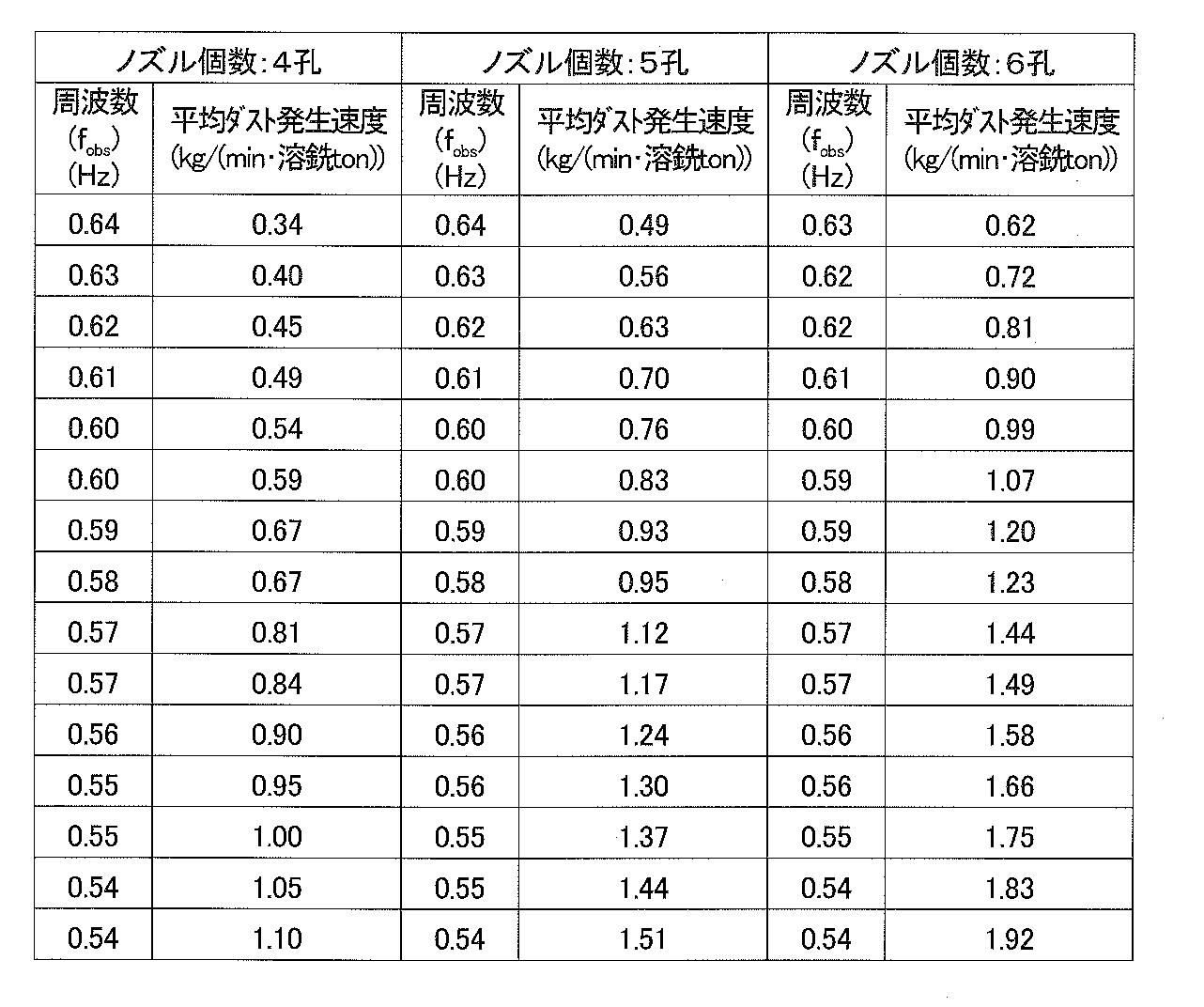
- FIG. 4 and Table 2 show the relationship between the average dust generation rate obtained from the average dust concentration in the exhaust gas and the frequency (f obs ) having the maximum amplitude among the converter vibration frequencies during decarburization refining. Is shown by the number of nozzles.
- the average dust generation rate was defined by the following equation (2).
- the average dust generation rate decreases with an increase in the frequency (f obs ) at which the amplitude is maximum among the converter vibration frequencies, but the frequency at which the amplitude is maximum (f obs ).
- the frequency (f obs ) at which the amplitude is maximum is an average dust with a natural frequency (f calc ) of 0.58 Hz as a boundary.
- the generation speed changes abruptly, and when the frequency (f obs ) at which the amplitude is maximum becomes larger than the natural frequency (f calc ), the average dust generation speed is reduced.
- a frequency (f obs ) having the maximum amplitude among the converter vibration frequencies is larger than the natural frequency (f calc ). It was found that it is important to adjust the lance height (L) and the top blowing oxygen gas flow rate.
- the present invention has been made on the basis of the above knowledge, and the converter operation monitoring method according to the present invention is such that an oxidizing gas is blown from the top blowing lance to the hot metal in the converter, or an oxidizing property is produced from the top blowing lance.
- the vibration of the converter is measured and the measured value is obtained by frequency analysis. It is essential to monitor the frequency of the converter vibration during decarburization and refining.
- frequency analysis data from the accelerometer body 7 is sequentially transmitted to the control computer 8, and the frequency (f obs ) with the maximum amplitude analyzed by the accelerometer body 7 is obtained.
- the control computer 8 send a signal for reducing the lance height (L) to the lance height controller 9?
- the oxygen gas flow rate control device 10 is configured to transmit a signal for decreasing the oxygen gas flow rate, or to transmit both.
- the oxidizing gas blown from the top blowing lance 3 is generally oxygen gas, but a mixed gas of oxygen gas and rare gas, air, oxygen-enriched air, or the like can be used.
- the oxidizing gas used in the present invention is any oxygen gas-containing gas having an oxygen concentration equal to or higher than that of air.
- an inert gas is blown from the bottom blowing tuyere 4, but an oxidizing gas may be blown from the bottom blowing tuyere.
- the oxidizing gas blown from the bottom blowing tuyere functions not only as an oxygen gas for decarburization refining but also as a stirring gas.
- the installation of the bottom blowing tuyere is not an essential condition in the present invention, and the gas blowing from the bottom blowing tuyere may not be performed.
- the inert gas is a rare gas such as argon gas or helium gas or nitrogen gas.
- the frequency of vibration due to the fluctuation of molten iron in the converter is monitored in real time during decarburization refining, the presence or absence of molten iron scattering due to the fluctuation of molten iron Can be predicted.
- the frequency (f obs ) having the maximum amplitude among the vibration frequencies of the converter is supplied from the top blowing lance so that the natural frequency (f calc ) of the converter becomes larger.
- the fluctuation of molten iron in the converter is suppressed and the scattering of molten iron to the outside of the furnace is reduced.
- Decarburization refining was performed using an upper-bottom blowing converter having a shape similar to that of the converter shown in FIG.
- the used top blowing lances are five Laval nozzle type injection nozzles of the same shape at the tip and are arranged at equal intervals on the same circumference with respect to the axis of the top blowing lance with a nozzle tilt angle of 14 °. is there.
- the throat diameter (d t ) of the injection nozzle is 73.6 mm
- the outlet diameter (d e ) of the injection nozzle is 78.0 mm.
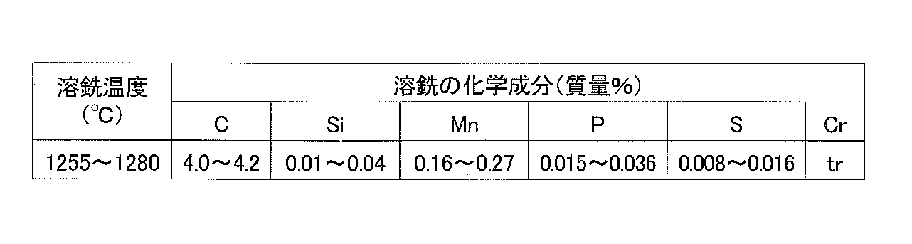
- dephosphorization was performed in advance, and hot metal having a temperature of 1255 to 1280 ° C. was charged into the top bottom blowing converter. Then, decarburization refining was started by blowing oxygen gas from the top blowing lance toward the hot metal bath surface while blowing argon gas from the bottom blowing tuyere into the hot metal as a stirring gas. The amount of iron scrap charged was adjusted so that the molten steel temperature at the end of decarburization refining was 1650 ° C. Table 3 shows the chemical components of the hot metal used.
- quick lime was added as a slagging agent from a furnace hopper (not shown), and decarburization refining was performed until the carbon concentration in the molten iron reached 0.05% by mass.
- the amount of quicklime was adjusted so that the basicity (mass% CaO / mass% SiO 2 ) of slag produced in the furnace was 2.5.
- the accelerometer sensor 6 was set on the trunnion shaft 12 of the converter, and the axial direction of the trunnion axis and the acceleration in the biaxial direction perpendicular to the axial direction were measured.
- the obtained acceleration signal was recorded by the accelerometer main body 7 and simultaneously subjected to fast Fourier transform processing.
- the frequency analysis of the converter vibration was performed in real time, and the frequency analysis data was transmitted to the control computer 8.
- the control computer operated the lance height control device 9 and the oxygen gas flow rate control device 10 as follows (example of the present invention).
- the lance The height control device was activated, and the lance height was controlled within a range that was reduced by up to 500 mm from the reference position.
- the oxygen gas flow rate control device is activated, and the frequency (f obs ) at which the amplitude is maximized is determined.
- the flow rate of the top blowing oxygen gas was decreased until it became higher than the natural frequency (f calc ).
- the natural frequency (f calc ) of the converter calculated from the equation (1) was 0.29 Hz.
- the converter equipment and the operation method are in accordance with the above-described example of the present invention, but decarburization refining was performed without operating the lance height controller and the oxygen gas flow controller (comparative example).
- the top blowing oxygen gas flow rate, the bottom blowing gas flow rate, and the dimensionless lance height (L / d e ) are set as shown in Table 4 according to the carbon concentration in the hot metal. did. That is, the top blown oxygen gas flow rate and the bottom blown gas flow rate were changed, and the dimensionless lance height (L / d e ) was changed, with the carbon concentration in the molten iron being 0.4% by mass.
- Table 5 shows the operating conditions and decarburization refining results in the present invention example and the comparative example.
- the top blowing lance height controller and the non-dimensionalized lance height are immediately activated.
- (L / d e ) was changed from 34.6 to 29.5.
- the frequency (f obs ) at which the amplitude was maximum increased to 0.32 Hz. Since the operation method is the same, the frequency (f obs ) at which the amplitude is maximum matched the natural frequency (f calc ) even in the comparative example, but in the comparative example, decarburization refining was performed without changing the operation conditions. Continued.
- the dust generation rate index in Table 5 is a relative value when the dust generation rate in the comparative example is 1.0.
Landscapes
- Engineering & Computer Science (AREA)
- Chemical & Material Sciences (AREA)
- Manufacturing & Machinery (AREA)
- Materials Engineering (AREA)
- Metallurgy (AREA)
- Organic Chemistry (AREA)
- Mechanical Engineering (AREA)
- General Engineering & Computer Science (AREA)
- Carbon Steel Or Casting Steel Manufacturing (AREA)
Abstract
Description





2 転炉
3 上吹きランス
4 底吹き羽口
5 溶銑
6 加速度計センサー
7 加速度計本体
8 制御用計算機
9 ランス高さ制御装置
10 酸素ガス流量制御装置
11 酸素ガス噴流
12 トラニオン軸
13 酸素ガス供給管
14 冷却水供給管
15 冷却水排出管
Claims (4)
- 転炉内の溶銑に上吹きランスから酸化性ガスを吹き付ける、または、上吹きランスから酸化性ガスを吹き付けるとともに底吹き羽口から酸化性ガスまたは不活性ガスを溶銑に吹き込んで溶銑の脱炭精錬を行う際に、
前記転炉の振動を測定し、該測定値を周波数解析することによって求められる、前記転炉の振動の周波数を脱炭精錬中に監視する転炉操業監視方法。 - 前記測定値を高速フーリエ変換することで、前記転炉の振動の周波数を求めることを特徴とする、請求項1に記載の転炉操業監視方法。
- 転炉内の溶銑に上吹きランスから酸化性ガスを吹き付ける、または、上吹きランスから酸化性ガスを吹き付けるとともに底吹き羽口から酸化性ガスまたは不活性ガスを溶銑に吹き込んで溶銑の脱炭精錬を行う際に、
前記転炉の振動を測定し、該測定値を周波数解析することによって前記転炉の振動の周波数を脱炭精錬中に求め、
求めた転炉振動の周波数のうちで、振幅が最大となる周波数(fobs)が、下記の(1)式で算出される転炉の固有振動数(fcalc)よりも大きくなるように、上吹きランスから吹き付ける酸化性ガスの流量、上吹きランスのランス高さのうちの何れか一方または双方を調整する転炉操業方法。

- 前記測定値を高速フーリエ変換することで、前記転炉の振動の周波数を求めることを特徴とする、請求項3に記載の転炉操業方法。
Priority Applications (5)
| Application Number | Priority Date | Filing Date | Title |
|---|---|---|---|
| KR1020167017141A KR20160091397A (ko) | 2013-11-28 | 2014-11-18 | 전로 조업 감시 방법 및 전로 조업 방법 |
| KR1020177033809A KR102157415B1 (ko) | 2013-11-28 | 2014-11-18 | 전로 조업 감시 방법 및 전로 조업 방법 |
| CN201480065046.XA CN105793444B (zh) | 2013-11-28 | 2014-11-18 | 转炉操作监视方法及转炉操作方法 |
| JP2015550553A JP6065126B2 (ja) | 2013-11-28 | 2014-11-18 | 転炉操業方法 |
| BR112016012017-5A BR112016012017B1 (pt) | 2013-11-28 | 2014-11-18 | método de operação de um conversor |
Applications Claiming Priority (2)
| Application Number | Priority Date | Filing Date | Title |
|---|---|---|---|
| JP2013-246076 | 2013-11-28 | ||
| JP2013246076 | 2013-11-28 |
Publications (1)
| Publication Number | Publication Date |
|---|---|
| WO2015079646A1 true WO2015079646A1 (ja) | 2015-06-04 |
Family
ID=53198621
Family Applications (1)
| Application Number | Title | Priority Date | Filing Date |
|---|---|---|---|
| PCT/JP2014/005764 Ceased WO2015079646A1 (ja) | 2013-11-28 | 2014-11-18 | 転炉操業監視方法及び転炉操業方法 |
Country Status (6)
| Country | Link |
|---|---|
| JP (1) | JP6065126B2 (ja) |
| KR (2) | KR20160091397A (ja) |
| CN (1) | CN105793444B (ja) |
| BR (1) | BR112016012017B1 (ja) |
| TW (1) | TWI572719B (ja) |
| WO (1) | WO2015079646A1 (ja) |
Cited By (2)
| Publication number | Priority date | Publication date | Assignee | Title |
|---|---|---|---|---|
| JP2022519386A (ja) * | 2018-10-23 | 2022-03-23 | ナカノ,ジンイチロウ | 炉ランスの位置を制御する方法 |
| JP2022059579A (ja) * | 2020-10-01 | 2022-04-13 | Jfeスチール株式会社 | 耐火物残存状況推定方法、耐火物残存状況推定装置および金属精錬炉 |
Families Citing this family (2)
| Publication number | Priority date | Publication date | Assignee | Title |
|---|---|---|---|---|
| CN110612356B (zh) * | 2017-05-08 | 2021-06-29 | 杰富意钢铁株式会社 | 转炉的操作方法 |
| CN111893237B (zh) * | 2020-07-08 | 2021-11-09 | 北京科技大学 | 一种转炉炼钢的熔池碳含量及温度全程实时预测方法 |
Citations (4)
| Publication number | Priority date | Publication date | Assignee | Title |
|---|---|---|---|---|
| JPS5377816A (en) * | 1976-12-22 | 1978-07-10 | Nippon Steel Corp | Discriminating and controlling method for converter conditions in blowing |
| JPH01195232A (ja) * | 1988-01-29 | 1989-08-07 | Nippon Steel Corp | 含鉄冷材の溶解完了時期検知方法 |
| JPH08269525A (ja) * | 1995-03-31 | 1996-10-15 | Sumitomo Metal Ind Ltd | 転炉のランス高さ制御方法 |
| JPH11199916A (ja) * | 1998-01-19 | 1999-07-27 | Kawasaki Steel Corp | スラグレベル検知機能付き転炉、転炉精錬時のスラグレベル検知方法および金属鉱石の溶融還元方法 |
Family Cites Families (6)
| Publication number | Priority date | Publication date | Assignee | Title |
|---|---|---|---|---|
| JPS54114414A (en) * | 1978-02-28 | 1979-09-06 | Kawasaki Steel Co | Controlling of scum formation of converter |
| JPS58213815A (ja) * | 1982-06-03 | 1983-12-12 | Kawasaki Steel Corp | 溶鋼の精錬過程管理方法 |
| JPH09176719A (ja) * | 1995-12-26 | 1997-07-08 | Sumitomo Metal Ind Ltd | 転炉および吹錬操業方法 |
| DE10253535A1 (de) * | 2002-11-16 | 2004-05-27 | Sms Demag Ag | Gaszuleitungssystem für einen metallurgischen Ofen sowie Betriebsverfahren hierzu |
| CN101016576B (zh) * | 2007-02-26 | 2010-10-13 | 河北钢铁股份有限公司 | 氧气顶吹转炉基于氧枪振动的炉渣状态检测方法及装置 |
| US8808421B2 (en) * | 2010-02-26 | 2014-08-19 | Tenova Goodfellow Inc. | System for furnace slopping prediction and lance optimization |
-
2014
- 2014-11-18 BR BR112016012017-5A patent/BR112016012017B1/pt not_active IP Right Cessation
- 2014-11-18 JP JP2015550553A patent/JP6065126B2/ja active Active
- 2014-11-18 KR KR1020167017141A patent/KR20160091397A/ko not_active Ceased
- 2014-11-18 CN CN201480065046.XA patent/CN105793444B/zh not_active Expired - Fee Related
- 2014-11-18 KR KR1020177033809A patent/KR102157415B1/ko not_active Expired - Fee Related
- 2014-11-18 WO PCT/JP2014/005764 patent/WO2015079646A1/ja not_active Ceased
- 2014-11-27 TW TW103141108A patent/TWI572719B/zh not_active IP Right Cessation
Patent Citations (4)
| Publication number | Priority date | Publication date | Assignee | Title |
|---|---|---|---|---|
| JPS5377816A (en) * | 1976-12-22 | 1978-07-10 | Nippon Steel Corp | Discriminating and controlling method for converter conditions in blowing |
| JPH01195232A (ja) * | 1988-01-29 | 1989-08-07 | Nippon Steel Corp | 含鉄冷材の溶解完了時期検知方法 |
| JPH08269525A (ja) * | 1995-03-31 | 1996-10-15 | Sumitomo Metal Ind Ltd | 転炉のランス高さ制御方法 |
| JPH11199916A (ja) * | 1998-01-19 | 1999-07-27 | Kawasaki Steel Corp | スラグレベル検知機能付き転炉、転炉精錬時のスラグレベル検知方法および金属鉱石の溶融還元方法 |
Non-Patent Citations (1)
| Title |
|---|
| CHRISTIAN WUPPERMANN ET AL.: "Physical and Mathematical Modeling of the Vessel Oscillation inthe AOD Process", ISIJ INTERNATIONAL, vol. 53, no. 3, 15 March 2013 (2013-03-15), pages 441 - 449 * |
Cited By (3)
| Publication number | Priority date | Publication date | Assignee | Title |
|---|---|---|---|---|
| JP2022519386A (ja) * | 2018-10-23 | 2022-03-23 | ナカノ,ジンイチロウ | 炉ランスの位置を制御する方法 |
| JP2022059579A (ja) * | 2020-10-01 | 2022-04-13 | Jfeスチール株式会社 | 耐火物残存状況推定方法、耐火物残存状況推定装置および金属精錬炉 |
| JP7400786B2 (ja) | 2020-10-01 | 2023-12-19 | Jfeスチール株式会社 | 耐火物残存状況推定方法、耐火物残存状況推定装置および金属精錬炉 |
Also Published As
| Publication number | Publication date |
|---|---|
| JPWO2015079646A1 (ja) | 2017-03-16 |
| CN105793444B (zh) | 2018-06-26 |
| KR102157415B1 (ko) | 2020-09-17 |
| TW201525146A (zh) | 2015-07-01 |
| KR20160091397A (ko) | 2016-08-02 |
| BR112016012017B1 (pt) | 2021-03-02 |
| KR20170132347A (ko) | 2017-12-01 |
| JP6065126B2 (ja) | 2017-01-25 |
| TWI572719B (zh) | 2017-03-01 |
| CN105793444A (zh) | 2016-07-20 |
Similar Documents
| Publication | Publication Date | Title |
|---|---|---|
| JP6065126B2 (ja) | 転炉操業方法 | |
| EP3620542B1 (en) | Converter operation monitoring method and converter operation method | |
| CN102791399B (zh) | 转炉喷溅预测和吹氧管优化系统 | |
| US11293069B2 (en) | Method for oxygen-blowing refining of molten iron and top-blowing lance | |
| JP6954262B2 (ja) | 転炉の操業方法 | |
| US6432163B1 (en) | Metal refining method using differing refining oxygen sequence | |
| JP2014037599A (ja) | 溶銑の精錬方法 | |
| JP5915568B2 (ja) | 転炉型精錬炉における溶銑の精錬方法 | |
| CN110612356B (zh) | 转炉的操作方法 | |
| EP3752650B1 (en) | Method for refining molten metal using a converter | |
| JP6421731B2 (ja) | 転炉の操業方法 | |
| JP2014521837A (ja) | 液体高炉銑などの液体溶銑を脱リンする方法および装置 | |
| JPH11199916A (ja) | スラグレベル検知機能付き転炉、転炉精錬時のスラグレベル検知方法および金属鉱石の溶融還元方法 | |
| JP2011084789A (ja) | 転炉吹錬方法 | |
| JPS62202013A (ja) | 転炉操業方法 | |
| JPS62196314A (ja) | 転炉操業方法 | |
| JP2025095607A (ja) | 精錬方法および転炉 | |
| WO2022195951A1 (ja) | 転炉の操業方法および溶鋼の製造方法 | |
| JP2022059473A (ja) | 冷鉄源溶解状況推定方法、冷鉄源溶解状況推定装置、金属精錬炉および溶鉄の製造方法 | |
| JPH05287346A (ja) | 炭材添加によるスラグフォーミング抑制方法 | |
| JP2000336418A (ja) | 転炉吹錬方法 | |
| JP2001011529A (ja) | 溶銑の予備処理方法 |
Legal Events
| Date | Code | Title | Description |
|---|---|---|---|
| 121 | Ep: the epo has been informed by wipo that ep was designated in this application |
Ref document number: 14866351 Country of ref document: EP Kind code of ref document: A1 |
|
| ENP | Entry into the national phase |
Ref document number: 2015550553 Country of ref document: JP Kind code of ref document: A |
|
| WWE | Wipo information: entry into national phase |
Ref document number: 2016/07115 Country of ref document: TR |
|
| NENP | Non-entry into the national phase |
Ref country code: DE |
|
| REG | Reference to national code |
Ref country code: BR Ref legal event code: B01A Ref document number: 112016012017 Country of ref document: BR |
|
| ENP | Entry into the national phase |
Ref document number: 20167017141 Country of ref document: KR Kind code of ref document: A |
|
| 122 | Ep: pct application non-entry in european phase |
Ref document number: 14866351 Country of ref document: EP Kind code of ref document: A1 |
|
| ENP | Entry into the national phase |
Ref document number: 112016012017 Country of ref document: BR Kind code of ref document: A2 Effective date: 20160525 |