WO2015079501A1 - レベリングバルブ - Google Patents
レベリングバルブ Download PDFInfo
- Publication number
- WO2015079501A1 WO2015079501A1 PCT/JP2013/081804 JP2013081804W WO2015079501A1 WO 2015079501 A1 WO2015079501 A1 WO 2015079501A1 JP 2013081804 W JP2013081804 W JP 2013081804W WO 2015079501 A1 WO2015079501 A1 WO 2015079501A1
- Authority
- WO
- WIPO (PCT)
- Prior art keywords
- valve
- valve body
- air
- operating arm
- leveling
- Prior art date
- Legal status (The legal status is an assumption and is not a legal conclusion. Google has not performed a legal analysis and makes no representation as to the accuracy of the status listed.)
- Ceased
Links
Images




Classifications
-
- B—PERFORMING OPERATIONS; TRANSPORTING
- B61—RAILWAYS
- B61F—RAIL VEHICLE SUSPENSIONS, e.g. UNDERFRAMES, BOGIES OR ARRANGEMENTS OF WHEEL AXLES; RAIL VEHICLES FOR USE ON TRACKS OF DIFFERENT WIDTH; PREVENTING DERAILING OF RAIL VEHICLES; WHEEL GUARDS, OBSTRUCTION REMOVERS OR THE LIKE FOR RAIL VEHICLES
- B61F5/00—Constructional details of bogies; Connections between bogies and vehicle underframes; Arrangements or devices for adjusting or allowing self-adjustment of wheel axles or bogies when rounding curves
- B61F5/02—Arrangements permitting limited transverse relative movements between vehicle underframe or bolster and bogie; Connections between underframes and bogies
- B61F5/22—Guiding of the vehicle underframes with respect to the bogies
-
- B—PERFORMING OPERATIONS; TRANSPORTING
- B61—RAILWAYS
- B61F—RAIL VEHICLE SUSPENSIONS, e.g. UNDERFRAMES, BOGIES OR ARRANGEMENTS OF WHEEL AXLES; RAIL VEHICLES FOR USE ON TRACKS OF DIFFERENT WIDTH; PREVENTING DERAILING OF RAIL VEHICLES; WHEEL GUARDS, OBSTRUCTION REMOVERS OR THE LIKE FOR RAIL VEHICLES
- B61F5/00—Constructional details of bogies; Connections between bogies and vehicle underframes; Arrangements or devices for adjusting or allowing self-adjustment of wheel axles or bogies when rounding curves
- B61F5/02—Arrangements permitting limited transverse relative movements between vehicle underframe or bolster and bogie; Connections between underframes and bogies
- B61F5/04—Bolster supports or mountings
- B61F5/10—Bolster supports or mountings incorporating fluid springs
Definitions
- the present invention relates to a leveling valve.
- JP2013-173438A discloses a leveling valve that adjusts the height of an air spring used in a railway vehicle.
- the leveling valve selectively connects the air spring to the compressor or the exhaust passage according to the turning direction of the lever that rotates according to the relative displacement of the vehicle body with respect to the carriage to maintain the vehicle body at a constant height.
- the leveling valve includes an air supply valve that switches communication between the air spring and the compressor, an exhaust valve that switches communication between the air spring and the exhaust passage, and an operating arm that transmits the rotation of the lever via the buffer spring. Prepare.
- Each of the air supply valve and the exhaust valve has a cylindrical sleeve and a valve body slidably disposed in the sleeve.
- the valve body of the air supply valve is biased in the valve closing direction by the air pressure of the compressor, and the valve body of the exhaust valve is biased in the valve closing direction by the air pressure of the air spring.
- the operating arm is rotated by the restoring force of the buffer spring that is deformed with the rotation of the lever, and the supply valve or the exhaust valve is opened by pressing the valve body of the supply valve or the exhaust valve.
- the pressure receiving area of the valve element increases, so the valve element is attached in the valve opening direction against the air pressure. It is also necessary to increase the pressing force of the working arm. Since the operating arm is rotated by the restoring force of the buffer spring that is deformed as the lever rotates, the buffer spring needs to be enlarged. Therefore, the valve case for accommodating the buffer spring is increased in size and the dimension of the leveling valve is increased.
- An object of the present invention is to provide a leveling valve capable of expanding a flow path area without increasing the size of a buffer spring.
- a leveling valve that adjusts the height of an air spring provided between a vehicle body and a carriage of a railway vehicle, the lever rotating according to the relative displacement of the vehicle body with respect to the carriage, An operating arm that is rotated by the restoring force of the buffer spring that is deformed as the lever is rotated, and a compressed air source that is opened against the air pressure by the rotation of the operating arm and is connected to the air spring passage that communicates with the air spring.
- connection valve that connects the exhaust passage, and the connection valve is pressed by the operating arm as the operating arm rotates, and moves in the valve opening direction, and the first valve body is seated and detached
- a second valve body having a first valve seat, and a sleeve having an annular second valve seat in which the first valve body and the second valve body are slidably disposed, and the second valve body is seated on and off.
- An engagement portion that engages with one valve body and moves the second valve body together with the first valve body in a valve opening direction, and the pressure receiving area of the second valve body is larger than the pressure receiving area of the first valve body .
- FIG. 1 is a mounting diagram of a leveling valve according to an embodiment of the present invention.
- FIG. 2 is a cross-sectional view of a leveling valve according to an embodiment of the present invention.
- FIG. 3 is an enlarged view of the exhaust valve.
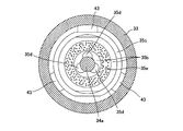
- 4A is a cross-sectional view showing a cross section 4A-4A in FIG. 4B is a cross-sectional view showing a 4B-4B cross section of FIG.
- FIG. 5 is a cross-sectional view showing a state where the first valve body of the exhaust valve is opened.
- FIG. 6 is a cross-sectional view showing a state where the second valve body of the exhaust valve is opened.
- FIG. 7 is a cross-sectional view showing a modification of the second valve body.
- FIG. 1 is an attachment diagram of the leveling valve 100 in the present embodiment.
- the leveling valve 100 has a function of adjusting the height of the air spring 3 provided between the vehicle body 1 and the carriage 2 of the railway vehicle to maintain the vehicle body 1 at a constant height.
- the leveling valve 100 is mounted between the vehicle body 1 and the carriage 2. Specifically, the leveling valve 100 is attached to the vehicle body 1 and connected to the carriage 2 via the lever 4 and the connecting rod 5. When the air spring 3 expands and contracts due to a load change of the vehicle body 1 and the height of the vehicle body 1 changes, this change is transmitted to the leveling valve 100 via the connecting rod 5 and the lever 4.
- the lever 4 When the vehicle body load increases and the air spring 3 bends, the lever 4 is pushed upward from the neutral position (rotation in the direction of arrow A in FIG. 1), and accordingly, the air supply valve of the leveling valve 100 31 (see FIG. 2) is opened, and an air spring passage 6 communicating with the air spring 3 and a compressor 7 serving as a compressed air source communicate with each other. Thereby, the compressed air from the compressor 7 is supplied to the air spring 3.
- the lever 4 returns to the neutral position, the air supply valve 31 of the leveling valve 100 is closed, and the supply of compressed air is shut off.
- the leveling valve 100 selectively communicates the air spring 3 with the compressor 7 or the exhaust passage 8 according to the turning direction of the lever 4 that rotates according to the relative displacement of the vehicle body 1 with respect to the carriage 2.
- the relative displacement generated between the vehicle body 1 and the carriage 2 is automatically adjusted to maintain the vehicle body 1 at a constant height.
- FIG. 2 is a sectional view of the leveling valve 100 in the present embodiment.
- FIG. 3 is an enlarged view of the exhaust valve 32.
- 4A is a cross-sectional view showing a cross section 4A-4A in FIG. 4B is a cross-sectional view showing a 4B-4B cross section of FIG.
- the leveling valve 100 includes a buffer spring portion 20 disposed in the center, an air supply valve 31 and an exhaust valve 32 as connection valves disposed in the upper portion, and an oil damper 25 disposed in the lower portion.
- the buffer spring portion 20 is provided with a swing arm (not shown) fixed to the shaft 21 to which the lever 4 is connected, an operating arm 22 that is rotatable with respect to the shaft 21, and an initial load concentrically applied to the shaft 21. And a shock absorbing spring 23 which is incorporated in a state where the swing arm is mounted and is in contact with the swing arm and the operating arm 22 at the same time.
- the rotation of the lever 4 is transmitted to the operating arm 22 via the swing arm and the buffer spring 23. That is, the operating arm 22 is rotated by the restoring force of the buffer spring 23 that is deformed as the lever 4 is rotated.
- the oil damper 25 includes a piston (not shown) that is connected to the proximal end side of the operating arm 22 and moves as the operating arm 22 rotates.
- the piston is disposed so as to be immersed in an oil chamber 12 formed in the valve case 11, and when the operating arm 22 rotates from the neutral position, it provides resistance to the rotating operation of the operating arm 22 while operating. When the arm 22 returns to the neutral position, little resistance is applied to the operating arm 22.
- the supply valve 31 and the exhaust valve 32 are arranged symmetrically around the distal end side of the operating arm 22 and are housed in the valve case 11.
- the valve case 11 is formed with a pair of valve housing holes 11 a having one end opened to the outer surface of the valve case 11 and the other end opened to the oil chamber 12.
- Each of the supply valve 31 and the exhaust valve 32 is stored in the valve storage hole 11a.
- the exhaust valve 32 includes a substantially cylindrical sleeve 33 that is fastened in the valve housing hole 11a, a first valve body 34 that is slidably disposed in the sleeve 33 and moves as the operating arm 22 rotates, And a second valve body 35 having a first valve seat 35a that is slidably disposed in the sleeve 33 and is annularly provided on the outer periphery of the first valve body 34, and the first valve body 34 is seated on and off.
- a male threaded portion 33a is formed on a part of the outer peripheral surface of the sleeve 33, and the sleeve 33 is engaged with the female threaded portion 11b formed on the inner periphery of the valve accommodating hole 11a, whereby the sleeve 33 is fitted into the valve accommodating hole 11a. Fastened inside. Further, a radially extending flange portion 33b is formed on the outer periphery of the sleeve 33. The flange portion 33b contacts the outer peripheral surface of the valve case 11 via the washer 13, so that the sleeve 33 is placed in the valve housing hole 11a. Is positioned.
- 33e and a fourth hole 33f having a diameter larger than that of the third hole 33e are formed in series.
- a second valve seat 33g on which the second valve body 35 is seated or separated is formed at the boundary step between the second hole 33d and the third hole 33e.
- the second valve seat 33g is formed so as to protrude from the sleeve 33 in the valve opening direction (right direction in FIG. 3), and there is a gap between the portion other than the second valve seat 33g of the sleeve 33 and the second valve body 35. It is formed.
- the first valve body 34 includes a sliding portion 34a that slides along the first hole 33c of the sleeve 33, and a valve body portion that is formed in a larger diameter than the sliding portion 34a and opens and closes the first valve seat 35a. 34b.
- the boundary step between the sliding portion 34a and the valve body portion 34b is seated on the first valve seat 35a to block the flow of compressed air, while being separated from the first valve seat 35a to allow the flow of compressed air.
- the seat portion 34 c to be formed is formed flat in the radial direction of the first valve body 34.
- the valve body portion 34b includes a first reduced diameter portion 34d having an outer diameter smaller than that of the valve body portion 34b on the side opposite to the sliding portion 34a, and a second reduced diameter portion 34e having an outer diameter smaller than that of the first reduced diameter portion 34d. Are formed in this order.
- the second valve element 35 is connected to the valve element part 35b and the valve element part 35b in an annular shape on the outer periphery of the sliding part 34a of the first valve element 34, and is extended in the valve opening direction. 34, and an annular extending portion 35c provided on the outer periphery of the valve body portion 35b.
- the inner periphery of the valve body portion 35b is in sliding contact with the outer periphery of the sliding portion 34a of the first valve body 34, and the outer periphery is screwed into the inner periphery of the extending portion 35c (FIG. 3).
- a notch-shaped connection passage 35d is formed along the sliding portion 34a of the first valve body 34 on the inner periphery of the valve body portion 35b.
- the connection passages 35d are provided at three locations in the circumferential direction of the valve body 35b, and are formed from the valve opening direction end of the valve body 35b to the valve closing direction end (FIG. 3).
- a first valve seat 35a to which the valve body portion 34b of the first valve body 34 is attached and detached is formed at the valve opening direction end of the valve body portion 35b.
- the valve body 35b is seated on the end of the valve closing direction on a second valve seat 33g formed so as to protrude from the sleeve 33 to block the flow of compressed air, while being compressed away from the second valve seat 33g.
- a seat portion 35e that allows the flow of air is formed flat in the radial direction of the second valve body 35.
- the extending portion 35c is formed such that the inner periphery has a predetermined gap with the valve body portion 34b of the first valve body 34, and the outer periphery has a predetermined gap with the third hole 33e.
- An engaging portion 35f having a reduced inner diameter is provided at the tip of the extending portion 35c.
- the extending portion 35c and the engaging portion 35f constitute a part of the second valve body.
- the engaging portion 35f has an inner diameter smaller than the outer diameter of the valve body portion 34b of the first valve body 34 and larger than the outer diameter of the first reduced diameter portion 34d. Further, the engagement portion 35f and the valve body portion 34b of the first valve body 34 are a predetermined distance in the axial direction (left-right direction in FIG. 3) when the first valve body 34 is seated on the first valve seat 35a. Only separated. As a result, when the first valve element 34 opens and moves in the valve opening direction by a predetermined distance, the first valve element 34 and the second valve element 35 engage and move integrally in the valve opening direction. .
- the extended portion 35c is further formed with a through hole 35g that penetrates the extended portion 35c in the radial direction.
- the through-hole 35g as a connection passage defines a passage through which air flows by connecting the inner peripheral side and the outer peripheral side of the extending portion 35c after the first valve element 34 is opened.
- a closing member 41 having a through-passage (not shown) in the axial center is press-fitted in the axial center.
- the closing member 41 closes the air chamber in the sleeve 33 in close contact with the boundary step between the third hole 33e and the fourth hole 33f.
- a communication passage 9 communicating with the compressor 7 is connected to the passage of the closing member 41 of the air supply valve 31, and an air spring passage 6 is connected to the passage of the closing member 41 of the exhaust valve 32.
- the communication passage 9 connected to the compressor 7 is connected to the high pressure port 47 of the air supply valve 31, and the air spring passage 6 is connected to the high pressure port 47 of the exhaust valve 32. It may be connected.
- a coil spring 42 that biases the first valve body 34 in the valve closing direction is provided in a compressed state.
- the coil spring 42 biases the first valve body 34 via a spring receiving member 43 that is fitted and fixed to the outer periphery of a second reduced diameter portion 34e formed in the valve body portion 34b of the first valve body 34.
- the spring receiving member 43 is in close contact with the second reduced diameter portion 34e of the first valve body 34, and the outer periphery is in sliding contact with the inner wall of the third hole 33e at three locations in the circumferential direction.
- a portion of the outer periphery of the spring receiving member 43 other than the sliding contact portion with the third hole 33e has a gap with the inner wall of the third hole 33e, and the air according to the sliding of the first valve body 34. Pass through.
- the spring receiving member 43 is press-fitted and fixed to the first valve body 34 and is slidably contacted with the inner wall of the third hole 33e, and the second valve body 35 is slid on the outer periphery of the sliding portion 34a of the first valve body 34. Since it contacts, the 1st valve body 34 and the 2nd valve body 35 are slidable to an axial direction, and the movement to radial direction is controlled.
- the sliding portion 34a of the first valve body 34 partially protrudes into the oil chamber 12, and in the state where the seat portion 34c is seated on the first valve seat 35a, the tip portion has a predetermined gap with the operating arm 22. To confront. When the operating arm 22 rotates more than a predetermined angle from the neutral position, the operating arm 22 comes into contact with the tip of the sliding portion 34a. The first valve body 34 moves against the urging force of the coil spring 42 as the operating arm 22 rotates, and opens when the seat portion 34c is separated from the first valve seat 35a. The second valve body 35 is engaged with the first valve body 34 via the engaging portion 35f by moving a predetermined distance in the valve opening direction after the first valve body 34 is opened, and thus the first valve body 34 is engaged. When the seat part 35e moves together with it and separates from the second valve seat 33g, the valve is opened.
- the leveling valve 100 provides a dead zone in which the supply and discharge of compressed air to and from the air spring 3 is prohibited, so that the air supply valve 31 and the exhaust valve 32 immediately after the operating arm 22 rotates from the neutral position. Has a predetermined gap between the operating arm 22 and the air supply valve 31 and the exhaust valve 32 so as not to be opened. Thereby, since supply / exhaust of the compressed air with respect to the air spring 3 can be prohibited with respect to the rotation of the operating arm 22 less than a predetermined angle, hunting of the air supply valve 31 and the exhaust valve 32 can be prevented. . Dead zones of the supply valve 31 and the exhaust valve 32 are set by adjusting the thickness or the number of washers 13.
- the sleeve 33 is partitioned from the first air chamber 44 by a first air chamber 44 that is always in communication with the exhaust passage 8, a first valve body 34, and a second valve body 35. 2 and a second air chamber 45 that is always in communication with the air conditioner 3. Note that the second air chamber 45 of the air supply valve 31 is always in communication with the compressor 7 through the communication passage 9.
- the second valve body 35 is provided on the outer periphery of the sliding portion 34 a of the first valve body 34, the pressure receiving area of the second valve body 35 is larger than the pressure receiving area of the first valve body 34. Therefore, when both the first valve body 34 and the second valve body 35 are closed, the second valve body 35 is moved in the valve closing direction by the differential pressure between the first air chamber 44 and the second air chamber 45. The force received is greater than the force that the first valve body 34 receives in the valve closing direction due to the differential pressure between the first air chamber 44 and the second air chamber 45.
- the sleeve 33 is formed with a low pressure port 46 communicating with the first air chamber 44 and a high pressure port 47 communicating with the second air chamber 45 through the inner and outer peripheral surfaces of the sleeve 33.
- the low pressure port 46 is always in communication with a first annular passage 48 formed in the valve case 11.
- the high pressure port 47 is always in communication with a second annular passage 49 formed in the valve case 11.
- the first annular passage 48 of the air supply valve 31 and the second annular passage 49 of the exhaust valve 32 communicate with each other through a communication passage 10 formed in the valve case 11. That is, the low pressure port 46 of the air supply valve 31 and the high pressure port 47 of the exhaust valve 32 communicate with each other through the communication passage 10.
- a check valve (not shown) that allows only the flow of compressed air from the low pressure port 46 of the air supply valve 31 to the high pressure port 47 of the exhaust valve 32 is provided in the communication passage 10.
- the low pressure port 46 of the exhaust valve 32 communicates with the exhaust passage 8 through the first annular passage 48.
- the operating arm 22 rotates more than a predetermined angle, the operating arm 22 presses the first valve body 34 of the exhaust valve 32. At this time, the first valve body 34 resists the force calculated by multiplying the differential pressure between the first air chamber 44 and the second air chamber 45 by the pressure receiving area that receives this differential pressure and the biasing force of the coil spring 42. Then move and open the valve. In this case, since only the first valve body 34 opens, the pressure receiving area is the pressure receiving area of only the first valve body 34 and does not include the pressure receiving area of the second valve body 35.
- the first air chamber 44 and the second air chamber 45 of the exhaust valve 32 pass through the connection passage 35d and the extending portion 35c of the second valve body 35. It communicates through the hole 35g. Further, when the first valve body 34 moves in the valve opening direction by a predetermined distance after the valve opening, the engaging portion 35 f is engaged with the first valve body 34.
- the differential pressure between the first air chamber 44 and the second air chamber 45 decreases. Further, since a gap is formed between the second valve body 35 and the end of the valve closing direction between the sleeve 33 and the second valve body 35, the first air chamber 44 and the second air chamber 45 are formed in the second valve body 35. Almost no force due to differential pressure.
- the first valve body 34 moves the second valve body 35 via the engaging portion 35f.
- the second valve body 35 includes the first air chamber 44 and the second air chamber 45. Since almost no force due to the differential pressure is applied, the pressing force required for the operating arm 22 to open the second valve body 35 hardly increases. That is, when both the first valve body 34 and the second valve body 35 are closed, the second valve body 35 receives in the valve closing direction due to the differential pressure between the first air chamber 44 and the second air chamber 45. The applied force is canceled as the first valve body 34 is opened.
- the compressed air of the air spring 3 is discharged to the atmosphere through the second air chamber 45, the first air chamber 44, the low pressure port 46 and the exhaust passage 8 of the exhaust valve 32.
- the high pressure port 47 of the exhaust valve 32 communicates with the low pressure port 46 of the air supply valve 31 through the communication passage 10, but the check air provided in the communication passage 10 causes the compressed air of the air spring 3 to be supplied to the air supply valve. It does not flow into the 31 side.
- the operating arm 22 rotates more than a predetermined angle, the operating arm 22 presses the first valve body 34 of the air supply valve 31. At this time, the first valve body 34 resists the force calculated by multiplying the differential pressure between the first air chamber 44 and the second air chamber 45 by the pressure receiving area that receives this differential pressure and the biasing force of the coil spring 42. Then move and open the valve. In this case, since only the first valve body 34 opens, the pressure receiving area is the pressure receiving area of only the first valve body 34 and does not include the pressure receiving area of the second valve body 35.
- the first air chamber 44 and the second air chamber 45 of the air supply valve 31 communicate with each other via the connection passage 35d of the second valve body 35 and the through hole 35g of the extending portion 35c. To do. Further, when the first valve body 34 moves in the valve opening direction by a predetermined distance after the valve opening, the engaging portion 35 f is engaged with the first valve body 34.
- the differential pressure between the first air chamber 44 and the second air chamber 45 decreases. Further, since a gap is formed between the second valve body 35 and the end of the valve closing direction between the sleeve 33 and the second valve body 35, the first air chamber 44 and the second air chamber 45 are formed in the second valve body 35. Almost no force due to differential pressure.
- the second valve body 35 moves in the valve opening direction together with the first valve body 34.
- the first air chamber 44 and the second air chamber 45 communicate with each other via the second valve body 35 and the sleeve 33.
- the first valve body 34 moves the second valve body 35 via the engaging portion 35f.
- the second valve body 35 includes the first air chamber 44 and the second air chamber 45. Since almost no force due to the differential pressure is applied, the pressing force required for the operating arm 22 to open the second valve body 35 hardly increases. That is, when both the first valve body 34 and the second valve body 35 are closed, the second valve body 35 receives in the valve closing direction due to the differential pressure between the first air chamber 44 and the second air chamber 45. The applied force is canceled as the first valve body 34 is opened.
- the compressed air of the air spring 3 pushes the check valve of the communication passage 10 from the second air chamber 45, the first air chamber 44, and the low pressure port 46 of the air supply valve 31 and opens the high pressure port of the exhaust valve 32. 47, supplied to the air spring 3 through the second air chamber 45.
- the operating arm 22 can open the second valve body 35 having a larger pressure receiving area than the first valve body 34 only by applying a force that presses the first valve body 34 in the valve opening direction. Therefore, a large flow path area can be ensured without increasing the size of the buffer spring 23 that applies the rotational force to the operating arm 22.
- the second valve seat 33g is formed to protrude from the sleeve 33 in the valve opening direction, and has a flow path between the inner periphery of the sleeve and the outer periphery of the second valve body 35.
- the air pressure can be guided to the gap between the valve closing direction end of the second valve body 35 and the second valve seat 33g formed on the sleeve 33 by the flow path. Since the second valve body 35 is always urged in the valve opening direction by this air pressure, the first valve body 34 is engaged after the first valve body 34 is opened as the operating arm 22 rotates. When moving in the valve opening direction together with the second valve body 35 via the portion 35f, an increase in the pressing force required for the operating arm 22 can be suppressed. Therefore, since the second valve body 35 can be opened more reliably, a large flow passage area can be secured without increasing the size of the buffer spring 23.
- the through hole 35g is formed in the extended portion 35c, the flow passage area of the passage that communicates the first air chamber 44 and the second air chamber 45 when the first valve body 34 is opened is increased.
- the differential pressure between the first air chamber 44 and the second air chamber 45 can be quickly reduced.
- the first valve body 34 is moved a predetermined distance after the valve is opened and engaged with the engaging portion 35f, the communication state between the first air chamber 44 and the second air chamber 45 can be maintained.
- the second valve body 35 can be opened more reliably.
- connection passage 35d is formed in a semicircular shape as shown in FIG. 4A, but the connection passage 55d may be formed in an elliptical shape as shown in FIG.
Landscapes
- Engineering & Computer Science (AREA)
- Mechanical Engineering (AREA)
- General Engineering & Computer Science (AREA)
- Vehicle Body Suspensions (AREA)
- Fluid-Damping Devices (AREA)
- Check Valves (AREA)
- Multiple-Way Valves (AREA)
Abstract
Description
Claims (4)
- 鉄道車両の車体と台車との間に設けられる空気ばねの高さを調整するレベリングバルブであって、
前記台車に対する前記車体の相対変位に応じて回動するレバーと、
前記レバーの回動に伴って変形する緩衝ばねの復元力によって回動する作動アームと、
前記作動アームの回動によってエア圧に抗して開弁し、前記空気ばねに連通する空気ばね通路に圧縮空気源又は排気通路を接続する接続弁と、
を備え、
前記接続弁は、
前記作動アームの回動に伴って前記作動アームに押圧されて開弁方向に移動する第1弁体と、
前記第1弁体が離着座する第1弁座を有する第2弁体と、
前記第1弁体及び前記第2弁体が内部に摺動自在に配置され、前記第2弁体が離着座する環状の第2弁座を有するスリーブと、
前記第2弁体に設けられ、前記第1弁体が開弁してから所定距離移動すると前記第1弁体に係合して前記第2弁体を前記第1弁体とともに開弁方向に移動させる係合部と、
を有し、
前記第2弁体の受圧面積は前記第1弁体の受圧面積より大きい、
レベリングバルブ。 - 請求項1に記載のレベリングバルブであって、
前記第2弁座は、開弁方向に前記スリーブから隆起して形成され、前記スリーブの内周と前記第2弁体の外周に流路を有する、
レベリングバルブ。 - 請求項1に記載のレベリングバルブであって、
前記第2弁体は、前記第1弁座と前記係合部との間に形成され前記第2弁体を径方向に貫通する貫通孔をさらに有する、
レベリングバルブ。 - 請求項1に記載のレベリングバルブであって、
前記接続弁は、前記作動アームが中立位置から一方向へ所定角度以上回動することによって開弁して前記空気ばね通路に前記圧縮空気源を接続する給気弁と、前記作動アームが中立位置から他方向へ所定角度以上回動することによって開弁して前記空気ばね通路に前記排気通路を接続する排気弁と、から構成される、
レベリングバルブ。
Priority Applications (6)
| Application Number | Priority Date | Filing Date | Title |
|---|---|---|---|
| CA2918866A CA2918866C (en) | 2013-11-26 | 2013-11-26 | Leveling valve |
| PCT/JP2013/081804 WO2015079501A1 (ja) | 2013-11-26 | 2013-11-26 | レベリングバルブ |
| CN201380078428.1A CN105408184B (zh) | 2013-11-26 | 2013-11-26 | 调平阀 |
| KR1020167002057A KR101847308B1 (ko) | 2013-11-26 | 2013-11-26 | 레벨링 밸브 |
| US15/027,437 US10035523B2 (en) | 2013-11-26 | 2013-11-26 | Leveling valve |
| JP2015550239A JP6353853B2 (ja) | 2013-11-26 | 2013-11-26 | レベリングバルブ |
Applications Claiming Priority (1)
| Application Number | Priority Date | Filing Date | Title |
|---|---|---|---|
| PCT/JP2013/081804 WO2015079501A1 (ja) | 2013-11-26 | 2013-11-26 | レベリングバルブ |
Publications (1)
| Publication Number | Publication Date |
|---|---|
| WO2015079501A1 true WO2015079501A1 (ja) | 2015-06-04 |
Family
ID=53198492
Family Applications (1)
| Application Number | Title | Priority Date | Filing Date |
|---|---|---|---|
| PCT/JP2013/081804 Ceased WO2015079501A1 (ja) | 2013-11-26 | 2013-11-26 | レベリングバルブ |
Country Status (6)
| Country | Link |
|---|---|
| US (1) | US10035523B2 (ja) |
| JP (1) | JP6353853B2 (ja) |
| KR (1) | KR101847308B1 (ja) |
| CN (1) | CN105408184B (ja) |
| CA (1) | CA2918866C (ja) |
| WO (1) | WO2015079501A1 (ja) |
Cited By (2)
| Publication number | Priority date | Publication date | Assignee | Title |
|---|---|---|---|---|
| CN107696820A (zh) * | 2017-08-22 | 2018-02-16 | 山东交通学院 | 针对复杂路况下的运输车辆瞬时高度控制装置 |
| WO2023176142A1 (ja) * | 2022-03-17 | 2023-09-21 | 日立Astemo株式会社 | バルブ装置 |
Families Citing this family (4)
| Publication number | Priority date | Publication date | Assignee | Title |
|---|---|---|---|---|
| US10035523B2 (en) * | 2013-11-26 | 2018-07-31 | Kyb Corporation | Leveling valve |
| JP6709101B2 (ja) * | 2016-04-13 | 2020-06-10 | Kyb株式会社 | レベリングバルブ |
| DE102016120639A1 (de) * | 2016-10-28 | 2018-05-03 | Voith Patent Gmbh | Vorrichtung zur horizontalen mittenrückstellung eines kupplungsschafts |
| KR20230061980A (ko) | 2021-10-29 | 2023-05-09 | 현대로템 주식회사 | 철도차량용 레벨링 밸브 |
Citations (8)
| Publication number | Priority date | Publication date | Assignee | Title |
|---|---|---|---|---|
| JPS4835964B1 (ja) * | 1969-06-27 | 1973-10-31 | ||
| JPS4962866A (ja) * | 1972-10-16 | 1974-06-18 | ||
| JPS4962865A (ja) * | 1972-10-14 | 1974-06-18 | ||
| JPS61105374A (ja) * | 1984-10-29 | 1986-05-23 | Nippon Fuirukon Kk | 濾過機用自動切替弁 |
| JPH07139643A (ja) * | 1993-06-16 | 1995-05-30 | Sagem Allumage Sa | 電動ゲートバルブおよびこれを備えたガソリン蒸気循環回路 |
| JPH11159632A (ja) * | 1997-11-26 | 1999-06-15 | Taisei Kinzoku Kogyosho:Kk | 開閉弁 |
| US20100213397A1 (en) * | 2009-02-24 | 2010-08-26 | Hadley Products | Height control valve for vehicle leveling system |
| JP2013173439A (ja) * | 2012-02-24 | 2013-09-05 | Kyb Co Ltd | レベリングバルブ |
Family Cites Families (13)
| Publication number | Priority date | Publication date | Assignee | Title |
|---|---|---|---|---|
| GB1264560A (ja) * | 1968-06-07 | 1972-02-23 | ||
| DE2218089C3 (de) * | 1972-04-14 | 1982-01-14 | Wegmann & Co, 3500 Kassel | Schienenfahrzeug, insbesondere Reisezugwagen mit Drehgestellen |
| US3970009A (en) * | 1973-09-24 | 1976-07-20 | Houdaille Industries, Inc. | Fluid railroad passenger car suspension |
| JPH08118938A (ja) * | 1994-10-21 | 1996-05-14 | Jidosha Kiki Co Ltd | 車高調整装置用の残圧バルブ |
| KR0138404B1 (ko) * | 1995-07-31 | 1998-06-01 | 전성원 | 캡 에어 서스팬션용 레벨링 밸브 |
| JP4972366B2 (ja) * | 2006-09-04 | 2012-07-11 | カヤバ工業株式会社 | 車体姿勢制御装置 |
| CN201494274U (zh) * | 2009-09-16 | 2010-06-02 | 浙江科力汽车配件有限公司 | 一种汽车高度阀 |
| US8079310B2 (en) * | 2009-11-25 | 2011-12-20 | LTK Consulting Services, Inc. | Vertical position compensating device for a vehicle |
| JP5601161B2 (ja) * | 2010-11-11 | 2014-10-08 | アイシン精機株式会社 | 車両のサスペンション制御装置 |
| JP5831830B2 (ja) * | 2011-08-11 | 2015-12-09 | Kyb株式会社 | 鉄道車両用制振装置 |
| JP5783932B2 (ja) * | 2012-02-24 | 2015-09-24 | カヤバ工業株式会社 | レベリングバルブ |
| JP5986941B2 (ja) * | 2013-02-28 | 2016-09-06 | Kyb株式会社 | レベリングバルブ |
| US10035523B2 (en) * | 2013-11-26 | 2018-07-31 | Kyb Corporation | Leveling valve |
-
2013
- 2013-11-26 US US15/027,437 patent/US10035523B2/en not_active Expired - Fee Related
- 2013-11-26 CN CN201380078428.1A patent/CN105408184B/zh not_active Expired - Fee Related
- 2013-11-26 WO PCT/JP2013/081804 patent/WO2015079501A1/ja not_active Ceased
- 2013-11-26 JP JP2015550239A patent/JP6353853B2/ja not_active Expired - Fee Related
- 2013-11-26 KR KR1020167002057A patent/KR101847308B1/ko not_active Expired - Fee Related
- 2013-11-26 CA CA2918866A patent/CA2918866C/en not_active Expired - Fee Related
Patent Citations (8)
| Publication number | Priority date | Publication date | Assignee | Title |
|---|---|---|---|---|
| JPS4835964B1 (ja) * | 1969-06-27 | 1973-10-31 | ||
| JPS4962865A (ja) * | 1972-10-14 | 1974-06-18 | ||
| JPS4962866A (ja) * | 1972-10-16 | 1974-06-18 | ||
| JPS61105374A (ja) * | 1984-10-29 | 1986-05-23 | Nippon Fuirukon Kk | 濾過機用自動切替弁 |
| JPH07139643A (ja) * | 1993-06-16 | 1995-05-30 | Sagem Allumage Sa | 電動ゲートバルブおよびこれを備えたガソリン蒸気循環回路 |
| JPH11159632A (ja) * | 1997-11-26 | 1999-06-15 | Taisei Kinzoku Kogyosho:Kk | 開閉弁 |
| US20100213397A1 (en) * | 2009-02-24 | 2010-08-26 | Hadley Products | Height control valve for vehicle leveling system |
| JP2013173439A (ja) * | 2012-02-24 | 2013-09-05 | Kyb Co Ltd | レベリングバルブ |
Cited By (4)
| Publication number | Priority date | Publication date | Assignee | Title |
|---|---|---|---|---|
| CN107696820A (zh) * | 2017-08-22 | 2018-02-16 | 山东交通学院 | 针对复杂路况下的运输车辆瞬时高度控制装置 |
| WO2023176142A1 (ja) * | 2022-03-17 | 2023-09-21 | 日立Astemo株式会社 | バルブ装置 |
| JPWO2023176142A1 (ja) * | 2022-03-17 | 2023-09-21 | ||
| JP7738163B2 (ja) | 2022-03-17 | 2025-09-11 | Astemo株式会社 | バルブ装置 |
Also Published As
| Publication number | Publication date |
|---|---|
| US20160251022A1 (en) | 2016-09-01 |
| CA2918866C (en) | 2017-01-03 |
| CA2918866A1 (en) | 2015-06-04 |
| CN105408184A (zh) | 2016-03-16 |
| JP6353853B2 (ja) | 2018-07-04 |
| KR101847308B1 (ko) | 2018-04-09 |
| KR20160024971A (ko) | 2016-03-07 |
| US10035523B2 (en) | 2018-07-31 |
| CN105408184B (zh) | 2017-10-03 |
| JPWO2015079501A1 (ja) | 2017-03-16 |
Similar Documents
| Publication | Publication Date | Title |
|---|---|---|
| JP6353853B2 (ja) | レベリングバルブ | |
| US20140360177A1 (en) | Variable pedal feeling adjustment device | |
| JP2008065820A (ja) | 切換レバー | |
| EP3093521B1 (en) | Vibration damping device for vehicle body | |
| TWI521156B (zh) | Gas spring | |
| US10060542B2 (en) | Leveling valve | |
| JP2006510845A (ja) | 温度制御されたピストン冷却用オイルスプレーノズル | |
| US9777792B2 (en) | Variable damping system using a piezoelectric device | |
| US20160098045A1 (en) | Aircraft hydraulic valve | |
| JP2019196779A5 (ja) | ||
| CN107949739B (zh) | 电磁阀 | |
| JP5783932B2 (ja) | レベリングバルブ | |
| JP5937466B2 (ja) | リリーフ弁装置 | |
| US20090293226A1 (en) | Spring hook wear bushing and linkage assembly including the spring hook wear bushing | |
| JP5869366B2 (ja) | レベリングバルブ | |
| TWI526350B (zh) | Horizontal valve | |
| KR102167502B1 (ko) | 스로틀 기능을 구비한 체크밸브 | |
| JP6709101B2 (ja) | レベリングバルブ | |
| US10233795B2 (en) | Bypass valve for pressure oscillation control | |
| JP5944872B2 (ja) | パイロットバルブ装置 | |
| JP2009024818A (ja) | ショックアブソーバー | |
| JP2008082462A (ja) | ロータリーダンパ | |
| US20200026312A1 (en) | Temperature sensor for coolant control valve | |
| WO2017208208A1 (en) | Valve for use with a pneumatic clutch actuation system | |
| JP2016203821A (ja) | 車両用液圧マスタシリンダ |
Legal Events
| Date | Code | Title | Description |
|---|---|---|---|
| WWE | Wipo information: entry into national phase |
Ref document number: 201380078428.1 Country of ref document: CN |
|
| 121 | Ep: the epo has been informed by wipo that ep was designated in this application |
Ref document number: 13898252 Country of ref document: EP Kind code of ref document: A1 |
|
| ENP | Entry into the national phase |
Ref document number: 2015550239 Country of ref document: JP Kind code of ref document: A |
|
| ENP | Entry into the national phase |
Ref document number: 2918866 Country of ref document: CA |
|
| ENP | Entry into the national phase |
Ref document number: 20167002057 Country of ref document: KR Kind code of ref document: A |
|
| WWE | Wipo information: entry into national phase |
Ref document number: 15027437 Country of ref document: US |
|
| NENP | Non-entry into the national phase |
Ref country code: DE |
|
| 122 | Ep: pct application non-entry in european phase |
Ref document number: 13898252 Country of ref document: EP Kind code of ref document: A1 |