WO2015075968A1 - 冷却装置、及びこれを備えた走行台車、車両 - Google Patents
冷却装置、及びこれを備えた走行台車、車両 Download PDFInfo
- Publication number
- WO2015075968A1 WO2015075968A1 PCT/JP2014/069439 JP2014069439W WO2015075968A1 WO 2015075968 A1 WO2015075968 A1 WO 2015075968A1 JP 2014069439 W JP2014069439 W JP 2014069439W WO 2015075968 A1 WO2015075968 A1 WO 2015075968A1
- Authority
- WO
- WIPO (PCT)
- Prior art keywords
- wheel
- axle
- cooling
- traveling
- rotation axis
- Prior art date
- Legal status (The legal status is an assumption and is not a legal conclusion. Google has not performed a legal analysis and makes no representation as to the accuracy of the status listed.)
- Ceased
Links
Images







Classifications
-
- B—PERFORMING OPERATIONS; TRANSPORTING
- B60—VEHICLES IN GENERAL
- B60T—VEHICLE BRAKE CONTROL SYSTEMS OR PARTS THEREOF; BRAKE CONTROL SYSTEMS OR PARTS THEREOF, IN GENERAL; ARRANGEMENT OF BRAKING ELEMENTS ON VEHICLES IN GENERAL; PORTABLE DEVICES FOR PREVENTING UNWANTED MOVEMENT OF VEHICLES; VEHICLE MODIFICATIONS TO FACILITATE COOLING OF BRAKES
- B60T5/00—Vehicle modifications to facilitate cooling of brakes
-
- B—PERFORMING OPERATIONS; TRANSPORTING
- B61—RAILWAYS
- B61B—RAILWAY SYSTEMS; EQUIPMENT THEREFOR NOT OTHERWISE PROVIDED FOR
- B61B13/00—Other railway systems
-
- B—PERFORMING OPERATIONS; TRANSPORTING
- B61—RAILWAYS
- B61B—RAILWAY SYSTEMS; EQUIPMENT THEREFOR NOT OTHERWISE PROVIDED FOR
- B61B13/00—Other railway systems
- B61B13/04—Monorail systems
-
- B—PERFORMING OPERATIONS; TRANSPORTING
- B61—RAILWAYS
- B61D—BODY DETAILS OR KINDS OF RAILWAY VEHICLES
- B61D1/00—Carriages for ordinary railway passenger traffic
-
- B—PERFORMING OPERATIONS; TRANSPORTING
- B61—RAILWAYS
- B61F—RAIL VEHICLE SUSPENSIONS, e.g. UNDERFRAMES, BOGIES OR ARRANGEMENTS OF WHEEL AXLES; RAIL VEHICLES FOR USE ON TRACKS OF DIFFERENT WIDTH; PREVENTING DERAILING OF RAIL VEHICLES; WHEEL GUARDS, OBSTRUCTION REMOVERS OR THE LIKE FOR RAIL VEHICLES
- B61F5/00—Constructional details of bogies; Connections between bogies and vehicle underframes; Arrangements or devices for adjusting or allowing self-adjustment of wheel axles or bogies when rounding curves
- B61F5/26—Mounting or securing axle-boxes in vehicle or bogie underframes
- B61F5/30—Axle-boxes mounted for movement under spring control in vehicle or bogie underframes
- B61F5/307—Axle-boxes mounted for movement under spring control in vehicle or bogie underframes incorporating fluid springs
-
- B—PERFORMING OPERATIONS; TRANSPORTING
- B61—RAILWAYS
- B61F—RAIL VEHICLE SUSPENSIONS, e.g. UNDERFRAMES, BOGIES OR ARRANGEMENTS OF WHEEL AXLES; RAIL VEHICLES FOR USE ON TRACKS OF DIFFERENT WIDTH; PREVENTING DERAILING OF RAIL VEHICLES; WHEEL GUARDS, OBSTRUCTION REMOVERS OR THE LIKE FOR RAIL VEHICLES
- B61F5/00—Constructional details of bogies; Connections between bogies and vehicle underframes; Arrangements or devices for adjusting or allowing self-adjustment of wheel axles or bogies when rounding curves
- B61F5/38—Arrangements or devices for adjusting or allowing self- adjustment of wheel axles or bogies when rounding curves, e.g. sliding axles, swinging axles
-
- B—PERFORMING OPERATIONS; TRANSPORTING
- B61—RAILWAYS
- B61F—RAIL VEHICLE SUSPENSIONS, e.g. UNDERFRAMES, BOGIES OR ARRANGEMENTS OF WHEEL AXLES; RAIL VEHICLES FOR USE ON TRACKS OF DIFFERENT WIDTH; PREVENTING DERAILING OF RAIL VEHICLES; WHEEL GUARDS, OBSTRUCTION REMOVERS OR THE LIKE FOR RAIL VEHICLES
- B61F5/00—Constructional details of bogies; Connections between bogies and vehicle underframes; Arrangements or devices for adjusting or allowing self-adjustment of wheel axles or bogies when rounding curves
- B61F5/50—Other details
- B61F5/52—Bogie frames
-
- B—PERFORMING OPERATIONS; TRANSPORTING
- B61—RAILWAYS
- B61H—BRAKES OR OTHER RETARDING DEVICES SPECIALLY ADAPTED FOR RAIL VEHICLES; ARRANGEMENT OR DISPOSITION THEREOF IN RAIL VEHICLES
- B61H1/00—Applications or arrangements of brakes with a braking member or members co-operating with the periphery of the wheel rim, a drum or the like
-
- F—MECHANICAL ENGINEERING; LIGHTING; HEATING; WEAPONS; BLASTING
- F16—ENGINEERING ELEMENTS AND UNITS; GENERAL MEASURES FOR PRODUCING AND MAINTAINING EFFECTIVE FUNCTIONING OF MACHINES OR INSTALLATIONS; THERMAL INSULATION IN GENERAL
- F16D—COUPLINGS FOR TRANSMITTING ROTATION; CLUTCHES; BRAKES
- F16D65/00—Parts or details
- F16D65/78—Features relating to cooling
- F16D65/84—Features relating to cooling for disc brakes
- F16D65/847—Features relating to cooling for disc brakes with open cooling system, e.g. cooled by air
Definitions
- the present invention relates to a cooling device that cools a brake device provided in a vehicle, and a traveling carriage and vehicle including the same.
- This application claims priority based on Japanese Patent Application No. 2013-240385 for which it applied on November 20, 2013, and uses the content here.
- an orbital transportation system that travels on a track by a traveling carriage provided with traveling wheels of rubber tires is known.
- Such an orbital transportation system is generally called a new transportation system or an APM (Automated People Mover).
- the vehicle traveling carriage in the track system is provided with a brake device such as a disc brake or a drum brake.
- the brake device is accommodated inside the rim
- Patent Document 1 a fan that rotates with the rotation of the wheel is provided inside the rim of the wheel provided in a bus, a truck, or the like, and air is forcibly sent into the rim to provide a brake device.
- a heat dissipation structure for cooling is described.
- the driving direction is basically one direction, but the vehicles of the new transportation system are operated with the driving direction being changed back and forth. Since the heat dissipation structure described in Patent Document 1 is provided on a bus or truck, air is sent to the inside of the rim by the rotation of the wheel when traveling in the forward direction, and traveling backwards The structure is not assumed. For this reason, even if this structure is simply applied to a vehicle of a track type traffic system, it is not possible to sufficiently cool the brake device provided inside the rim of the wheel.
- An object of the present invention is to provide a cooling device that can maintain a braking performance by cooling a brake device housed in a wheel regardless of the traveling direction, and a traveling carriage and a vehicle including the same.
- the brake device is disposed on the inner side and provided on the wheel of the traveling wheel that rotates integrally with the axle, and the wheel is moved in both forward and reverse directions by rotation in the forward and reverse directions.
- a plurality of the cooling fins in the first aspect are formed on the wheel as the ventilation hole on a circumference around the axis of rotation of the axle.
- the air flow may be generated through a decorative hole.
- Air can be generated by cooling fins through decorative holes formed for the purpose of weight reduction and ventilation inside and outside the wheel. Therefore, it is not necessary to newly form a ventilation hole that communicates between the inside and outside of the wheel in order to generate an air flow toward the inside and outside of the wheel, and the cost for newly forming the ventilation hole can be suppressed.
- the cooling fin in the first or second aspect may generate an airflow in a direction along the rotation axis of the axle.
- the airflow can be directly applied to the brake device, and the cooling effect of the brake device can be improved.
- the airflow after recovering the heat generated from the brake device by such an airflow is quickly circulated in a direction away from the wheel, so that efficient exhaust heat can be achieved.
- the cooling device at the end of the wheel hub that fixes the axle and the wheel in any one of the first to third aspects on the side away from the axle.
- a plate-like member that is provided and rotates with the axle may be provided, and the cooling fin may be formed on the plate-like member.
- a plurality of the cooling fins in the fourth aspect are formed on the plate-like member on a circumference centering on the axis of rotation of the axle.
- the cooling fin extends from the plate-like member in the direction of the rotation axis in an inclined manner toward one side in the circumferential direction of the rotation axis as it goes away from the axle.
- a through-hole penetrating the plate member may be formed in a region on the plate member corresponding to the region where the cooling fin is provided on the inclined side.
- the rotation direction of the wheel coincides with one side in the circumferential direction, that is, the direction in which the cooling fin extends.
- the wheel rotates airflow from the outside to the inside of the wheel is generated.
- the rotation direction of the wheel coincides with the other side in the circumferential direction that is, when the wheel rotates in the direction opposite to the direction in which the cooling fins extend, an air flow from the inside to the outside of the wheel is generated. Therefore, it is possible to generate an airflow passing through the brake device regardless of whether the rotation direction of the wheel is normal or reverse.
- a cooling device is provided in the wheel according to any one of the first to fifth aspects, and rotates integrally with the wheel, and the air flow from the cooling fin is transmitted to the ventilation air.
- An air guide member that leads to the hole may be further provided.
- the air guide member in the sixth aspect is a cylindrical shape centering on the rotational axis that covers the ventilation hole from the radially outer side of the rotational axis of the axle. You may have done.
- the air guide member in the seventh aspect includes a main body having a cylindrical shape centering on a rotation axis of the axle, and an outer peripheral surface of the main body.
- a through-hole penetrating the main body may be formed in a region on the outer peripheral surface of the main body corresponding to the region where the air guide member fin is provided.
- the rotation direction of the wheel coincides with one side in the circumferential direction, that is, the wind guide member fin.
- the wheel rotates in the direction in which the wheel extends, an air flow is generated from the outside of the wheel to the inside in the radial direction of the rotation axis.
- the rotation direction of the wheel coincides with the other side of the circumferential direction, that is, when the wheel rotates in the direction opposite to the direction in which the cooling fins extend, from the inside of the wheel to the outside, in the radial direction of the rotation axis A heading airflow is generated.
- the air guide member in the sixth aspect may have a tubular shape surrounding the opening of the ventilation hole from the outer peripheral side.
- the cross-sectional area of the airflow flowing through the air guide member can be reduced. Therefore, the flow velocity of the airflow flowing through the air guide member is increased, and the heat dissipation effect by the airflow passing through the brake device can be improved.
- the air guide member in any one of the sixth to ninth aspects is provided with a rubber member between the wheel serving as an end in the rotational axis direction. May be provided.
- the air guide member when the air guide member is provided separately from the wheel, the adhesion between the wheel and the air guide member can be improved, and dropping of the air guide member from the wheel can be restricted. Moreover, the clearance gap between a wind guide member and a wheel is filled, the leakage of the airflow between a wind guide member and a wheel can be suppressed, and more airflows can be sent to a brake device.
- a traveling vehicle includes an axle that rotates about a rotation axis, a pair of left and right traveling wheels that have a wheel and rotate integrally with the axle, and the pair of traveling wheels.
- a cooling device according to any one of the first to tenth aspects provided on the wheel, the guide device being guided by a guide rail extending along a track.
- the cooling fin can generate an airflow that passes through the brake device inside the wheel. Become. Therefore, the brake device can be cooled even when the traveling direction of the traveling carriage is changed back and forth.
- both of the cooling devices may be provided so as to generate an air flow toward the axle or to generate an air flow from the axle toward the wheel.
- the airflow generated by the cooling fins by the pair of left and right wheels of the traveling wheels flows so as to be close to each other or away from each other.
- the forces of the airflow generated in the pair of left and right cancel each other, and the influence of the airflow on the traveling of the traveling carriage can be reduced.
- both of the cooling devices rotate the axle.
- the cooling fins that generate an air flow toward one side in the direction of the axis may be provided.
- the airflow generated by the cooling fins at the pair of left and right traveling wheels is circulated in the same direction. Therefore, it can suppress that the airflow produced in the left-right pair mutually interferes, and can produce the flow of the airflow which passes smoothly through a brake device.
- a vehicle according to a fourteenth aspect of the present invention includes a vehicle body having a space formed therein, and a traveling carriage according to any one of the eleventh to thirteenth aspects provided at a lower portion of the vehicle body, Is provided.
- the traveling carriage including the cooling device since the traveling carriage including the cooling device is provided, the airflow that passes through the brake device inside the wheel by the cooling fin is generated regardless of which direction the wheel of the traveling wheel rotates. Can be generated. Therefore, the brake device can be cooled even when the traveling direction of the vehicle is changed back and forth.
- the cooling performance of the brake device accommodated in the wheel can be maintained by the cooling fins of the cooling device regardless of the traveling direction, and the braking performance can be maintained.
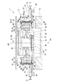
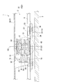
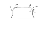
- FIG. 2 is a cross-sectional view showing the traveling carriage of the vehicle according to the first embodiment of the present invention, and is a cross-sectional view taken along the line BB of FIG. It is a figure which shows the wheel in the vehicle which concerns on 1st embodiment of this invention, Comprising: It is the figure seen from the width direction outer side of the rotating shaft direction.
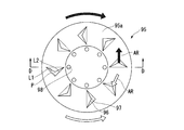
- FIG. 4B is a diagram showing a wheel in the vehicle according to the first embodiment of the present invention, and is a diagram showing a CC cross section of FIG. 4A. It is a figure which shows the cooling device in the vehicle which concerns on 1st embodiment of this invention, Comprising: It is the figure seen from the width direction outer side of the rotating shaft direction. It is a figure which shows the cooling device in the vehicle which concerns on 1st embodiment of this invention, Comprising: It is a figure which shows the DD cross section of FIG. 5A. It is a front view which shows the traveling trolley
- FIG. 8 is a view showing a wind guide member in a vehicle according to a second embodiment of the present invention, and showing a cross section taken along line EE of FIG. 7A. It is a figure which shows the air guide member in the vehicle which concerns on 2nd embodiment of this invention, Comprising: It is a figure which shows FF cross section. It is a figure which shows the air guide member in the vehicle which concerns on 2nd embodiment of this invention, Comprising: It is a figure which shows FF cross section.
- the vehicle 1 which concerns on 1st embodiment of this invention is demonstrated in detail with reference to drawings.
- the vehicle 1 is a vehicle of a track-type traffic system that travels on the track 5 while being guided by guide rails 6 provided on the track 5.
- the vehicle 1 is a vehicle of a side guide rail type (side guide type) transportation system in which guide rails 6 extending along the extending direction of the track 5 are provided on both sides in the width direction of the track 5. is there.
- the vehicle 1 includes a traveling carriage 2 that travels on a track 5 and a vehicle body 3 (see FIG. 1) supported by the traveling carriage 2.
- the directions such as front, rear, up, down, left and right are the same as the directions of the vehicle 1 unless otherwise specified.
- the arrow DI direction along the front-rear direction of the vehicle 1 is the front, and the direction opposite to the arrow DI direction is the rear.
- a direction toward a later-described subframe 11 disposed in the center of the traveling carriage 2 is referred to as a width direction inner side
- a direction away from the subframe 11 is referred to as a width direction outer side.
- the vehicle body 3 has a rectangular parallelepiped shape that is long in the front-rear direction, and a space capable of accommodating passengers is formed therein.
- a pair of traveling carriages 2 described above are provided before and after the lower portion of the vehicle body 3 (not shown). Since the front traveling carriage 2 and the rear traveling carriage 2 have the same configuration except that the front and rear directions are opposite, one (front) traveling carriage 2 will be described below as a representative.
- the traveling carriage 2 includes a subframe 11 disposed in the center in the width direction, and a pair of left and right axles 12 rotatably supported by the subframe 11 (see FIG. 2). And traveling wheels 13 connected to the respective axles 12.
- the traveling carriage 2 includes a guide device 14 guided by the guide rail 6, a steering mechanism 15 (see FIG. 1) that steers the traveling wheels 13 according to the displacement of the guide device 14, and the frame 3 a of the vehicle body 3.
- a suspension device 16 disposed between the wheel 13 and the wheel 13 is provided.
- the traveling carriage 2 includes a brake device 17 provided on the traveling wheel 13 and a cooling device 18 that cools the brake device 17.
- a speed reduction mechanism such as a differential gear for transmitting rotational power from a drive source such as a motor (not shown) to the axle 12 is accommodated.
- each axle 12 extends in the width direction, and an end on the inner side in the width direction is connected to a speed reduction mechanism in the subframe 11 via a joint 23 that can swing. ing. That is, the rotational power transmitted from the drive source via the speed reduction mechanism is distributed to the axles 12 so that each axle 12 rotates about the rotational axis O.
- each axle 12 on the outer side in the width direction is connected to a traveling wheel mounting shaft 27 to which the traveling wheel 13 is attached via a joint 24 that can swing.
- the traveling wheel mounting shaft 27 rotates with the axle 12 around the rotation axis O.
- Each traveling wheel mounting shaft 27 can swing around a king pin 26 (see FIG. 1) extending in the vertical direction. That is, the king pin 26 has a function as a steering shaft of the traveling wheel 13.
- the suspension device 16 includes a first suspension mechanism 51 that supports the above-described traveling wheels 13 so as to be displaceable in the vertical direction independently of the subframe 11 and a subframe 3a.
- a second suspension mechanism 52 (see FIG. 3) that supports the frame 11 so as to be displaceable in the vertical direction, and a pair of left and right air springs 53 disposed between the above-described frame 3a and the first suspension mechanism 51 are provided. ing.
- the first suspension mechanism 51 is a so-called double wishbone independent suspension mechanism.
- the first suspension mechanism 51 includes a pair of left and right upper arms 61 and a lower arm 62 that extend along the width direction.
- the upper arm 61 has an H shape in a plan view as viewed from above, and both end portions in the width direction are bifurcated with respect to the central portion.
- the inner end in the width direction is pin-coupled to the subframe 11, and the outer end is pin-coupled to the king pin 26 described above.
- the lower arm 62 has an H shape in a plan view as viewed from above, and both end portions in the width direction are bifurcated with respect to the central portion.
- the inner end in the width direction is pin-coupled below the upper arm 61 in the subframe 11
- the outer end is pin-coupled below the upper arm 61 in the king pin 26 described above.
- the first suspension mechanism 51 can swing in the vertical direction with respect to the traveling wheel 13 and the subframe 11 when the traveling wheel 13 is displaced in the vertical direction due to the unevenness of the track 5.
- the second suspension mechanism 52 is a so-called parallel link mechanism, and includes a pair of left and right upper links 71 and lower links 72 that extend in parallel to each other.
- Each of the upper link 71 and the lower link 72 is inclined and extends upward as it goes rearward, and its rear end is pin-coupled to a suspension frame 73 that extends downward from the frame 3a. Yes.
- the front end portions of the upper link 71 and the lower link 72 are pin-coupled to the rear end portion of the subframe 11.
- the second suspension mechanism 52 can swing in the vertical direction with respect to the suspension frame 73 and the subframe 11 in accordance with the relative movement of the suspension frame 73 and the subframe 11 in the vertical direction.
- the second suspension mechanism 52 also has a function as a traction rod for transmitting the driving force and braking force of the traveling wheel 13 to the vehicle body 3.
- the upper end of the air spring 53 is attached to the frame 3a, and the lower end thereof is attached to the upper surface of each upper arm 61 separately.
- the air spring 53 reduces the vertical vibration of the traveling wheel 13 relative to the vehicle body 3.
- the guide device 14 includes a guide frame 31, a guide frame support mechanism 32 for connecting the guide frame 31 to the subframe 11, and guide wheels 33 that are rotatably supported by the guide frame 31.
- the guide frame 31 is incorporated in a cross-beam shape when viewed from above and below, and is disposed below the subframe 11. Specifically, the guide frame 31 is connected to a pair of left and right vertical beams 34 extending in the front-rear direction, and a pair of horizontal beams 35 connected to both ends of the vertical beams 34 along the front-rear direction and extending in the width direction. And.
- Both ends of the longitudinal beam 34 in the front-rear direction are positioned on the outer side in the width direction than the traveling wheel 13, and the lateral beam 35 is connected to the outer side in the width direction with respect to the traveling wheel 13.
- Each lateral beam 35 has both ends in the width direction positioned on the outer side in the width direction with respect to each traveling wheel 13 and is disposed so as to sandwich the traveling wheel 13 from both sides in the front-rear direction.
- One guide wheel 33 is attached to each end of each transverse beam 35 in the width direction.
- the guide wheel 33 is supported so as to be rotatable around a rotation axis O ⁇ b> 1 extending along the vertical direction, and rolls by contacting the guide rail 6.
- a branch guide wheel 36 is provided below the guide wheel 33 in the guide frame 31, and rolls in contact with a branch guide rail (not shown) provided on the track 5 at a branch portion on the track 5. Guide to the branch direction.
- the guide frame support mechanism 32 is disposed below the subframe 11.
- the end portion on the outer side in the width direction of the guide frame support mechanism 32 is located on the inner side in the width direction with respect to the end portion on the outer side in the width direction of the first suspension mechanism 51 (the arms 61 and 62).
- the guide frame support mechanism 32 has a swivel bearing 43. By this slewing bearing 43, the guide frame 31 is supported with respect to the subframe 11 so as to be pivotable about a pivot axis O2 extending in the vertical direction.
- the slewing bearing 43 includes an outer ring and an inner ring, and either the outer ring or the inner ring is fixed to the guide frame support mechanism 32 and the other is fixed to the guide frame 31.
- the turning axis O2 is located at the front and rear and the left and right central portions of the guide frame 31.
- the steering mechanism 15 changes the steering angle of the traveling wheels 13 in conjunction with the turning of the guide frame 31 around the turning axis O2.
- the steering mechanism 15 includes a steering arm 41 that swings integrally with the traveling wheel 13 (the traveling wheel mounting shaft 27) with respect to each king pin 26, and a steering that connects the steering arm 41 and the guide frame 31 separately. Rod 42.
- the steering rod 42 extends along the width direction. An end portion on the outer side in the width direction of the steering rod 42 is pin-coupled to a front end portion of the steering arm 41, and an end portion on the inner side in the width direction is pin-coupled to the guide frame 31.
- the traveling wheels 13 are single tires attached to the axles 12 one by one via the traveling wheel mounting shafts 27.
- the traveling wheel 13 includes a bottomed cylindrical wheel 29 attached to a traveling wheel mounting shaft 27 and a rubber tire 30 that covers the wheel 29.
- the rubber tire 30 may be, for example, a core type in which a core is housed, or may be a type without a core used for a general truck or bus.
- the wheel 29 is formed so as to extend inward in the width direction from a disk-shaped center disk 80 positioned on the outermost side in the width direction and a radially outer edge of this end face. And a hub 28 for fixing the axle 12 and the wheel 29 via the traveling wheel mounting shaft 27.
- the center portion of the center disk 80 coincides with the rotation axis O, and an insertion hole 82 around the rotation axis O is formed at this center portion. Further, the center disk 80 is formed with a plurality of bolt mounting holes 84 on a circumference centering on the rotation axis O at a position radially outward from the insertion hole 82.
- the center disk 80 has a plurality of decorative holes 83 on the circumference centering on the rotational axis O as vent holes communicating with the inside and outside of the wheel 29 at positions radially outside the rotational axis O with respect to the bolt mounting holes 84. Is formed.
- the decorative hole 83 is provided for the purpose of reducing the weight of the wheel 29 and improving the air permeability between the inside and the outside of the wheel 29 in the width direction.
- the decoration hole 83 is formed at the end position on the radially outer side of the rotation axis O.
- Each decoration hole 83 is formed so as to be inclined from the outer side in the radial direction of the rotation axis O toward the inner side as it goes from the outer side in the width direction toward the inner side.
- the center disk 80 has a shape that is chamfered at the outer edge portion in the radial direction. Thereby, the opening part on the outer side in the width direction of the decoration hole 83 is inclined with respect to the rotation axis O and opens toward the outer side in the radial direction.
- the hub 28 is attached to the outer end in the width direction of the traveling wheel attachment shaft 27 and is inserted into the insertion hole 82 of the center disk 80, and a bolt 85 (see FIG. 2) is inserted into the bolt attachment hole 84 of the center disk 80.
- the center disk 80 is fixed by being inserted.
- the tip of the hub 28 protrudes outward in the width direction from the center disk 80.
- the brake device 17 is disposed on the inner side of the rim 81 in the wheel 29, that is, on the inner side in the width direction than the center disk 80.
- the brake device 17 includes a brake disc 90 fixed to the hub 28 of the wheel 29 and a brake caliper 91 including a brake pad (not shown) that can clamp the brake disc 90 from both sides of the rotation axis O.
- the brake device 17 of this embodiment is a disc brake.
- the brake pads in the brake caliper 91 can apply a braking force to the traveling wheels 13 by holding the brake disc 90 by hydraulic pressure or pneumatic pressure.
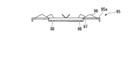
- the cooling device 18 is formed on a plate-like member 95 provided at the outer end of the hub 28 that protrudes outward in the width direction from the center disk 80 of the wheel 29, and is formed on the plate-like member 95. And a cooling fin 96 that generates an air flow AR passing through the.
- the plate-like member 95 is formed in a disc shape, and is fixed to the hub 28 with the center coinciding with the rotation axis O. That is, the plate-like member 95 is formed with a bolt mounting hole 98 on the circumference around the rotation axis O. The plate member 95 is fixed to the hub 28 by inserting a bolt 99 (see FIG. 2) through the bolt mounting hole 98.
- the region outside the rotational axis O in the radial direction from the position where the bolt mounting hole 98 is formed is the center disk 80 of the wheel 29 and the hub 28 when the plate-like member 95 is attached to the hub 28.
- an annular projecting portion 95a projecting annularly outward is formed.
- a plurality of cooling fins 96 are formed on the annular protrusion 95a of the plate-like member 95 on the circumference around the rotation axis O so as to be spaced apart from each other at equal intervals in the circumferential direction.
- Each cooling fin 96 is formed from the annular protrusion 95a toward the outside in the width direction. More specifically, one side in the circumferential direction of the rotation axis O toward the side away from the axle 12 in the direction of the rotation axis O (counterclockwise direction side toward the plane of FIG. 5A, direction of the white arrow) ) Inclining toward.
- a through hole 97 that penetrates the annular protrusion 95a in the direction of the rotation axis O is formed in a region on the annular protrusion 95a corresponding to the region where the cooling fin 96 is provided on the inclined side of the cooling fin 96. Yes.
- the cooling fins 96 and the through holes 97 are formed at positions corresponding to the radial positions where the decorative holes 83 are formed in the center disk 80 of the wheel 29.
- the cooling fins 96 and the through holes 97 corresponding to the cooling fins 96 are integrally formed. That is, in the annular protrusion 95a, cuts of two sides L1 and L2 sandwiching the apex P among the triangles having the apex P located on one side in the circumferential direction of the rotation axis O when viewed from the direction of the rotation axis O are formed. To do. Thereafter, the through hole 97 and the triangular cooling fin 96 are formed by lifting the apex P and the two sides L1 and L2 from the surface of the annular protrusion 95a.
- the cooling fins 96 and the through holes 97 may be formed separately, and their shapes are not limited to the case of this embodiment.
- the braking device inside the rim 81 of the wheel 29 is provided by the cooling fin 96 of the cooling device 18. It is possible to generate an airflow AR that passes through 17.
- the cooling fin 96 extends on the plate member 95 in an inclined manner toward one side in the circumferential direction of the rotation axis O. Therefore, when the rotation direction of the wheel 29 coincides with one side of the circumferential direction, that is, when the direction of the white arrow in FIG. 5A is the rotation direction, the direction of the white arrow toward the through hole 97 is set. Airflow AR is generated. As a result, an airflow AR is generated in the wheel 29 from the outside to the inside of the wheel 29.
- the brake device 17 can be cooled even when traveling with the traveling direction changed.
- the amount of heat transferred from the brake device 17 to the rubber tire 30 through the wheel 29 can be reduced, and the life of the rubber tire 30 can be prevented from being shortened.
- the cooling of the brake disc 90 can suppress the occurrence of cracks in the brake disc 90 due to the generation of thermal stress, the durability of the brake device 17 can be improved.
- the hydraulic brake it is possible to suppress overheating of the brake oil, and thus it is possible to suppress the occurrence of vapor lock.
- the cooling of the brake caliper 91 can extend the life of the brake pad provided on the brake caliper 91.
- the amount of heat transferred from the brake device 17 to the hub 28 can be reduced, seizure of a bearing or the like (not shown) that supports the traveling wheel 13 can be suppressed, and the rotational performance of the traveling wheel 13 is maintained. be able to.
- the vehicle 1 is provided with a regenerative brake as a device for applying a braking force to the traveling wheels 13, but the vehicle 1 can travel without impairing the brake performance by using the brake device 17 even after the regeneration is invalidated. Therefore, it is possible to continue high speed driving. Therefore, there is no hindrance to steady operation, leading to improved reliability.
- the cooling fins 96 are provided so as to generate an airflow AR in a direction along the rotation axis O of the axle 12. For this reason, the airflow AR can be directly applied to the brake device 17, and the cooling effect of the brake device 17 can be improved. Moreover, the airflow AR after recovering the heat generated from the brake device 17 is circulated in the direction away from the wheel 29 quickly by such an airflow AR, thereby enabling efficient exhaust heat.
- the cooling fin 96 can be easily provided on the wheel 29 by attaching the plate-like member 95 formed with the cooling fin 96 to the hub 28.
- the air flow AR can be generated by the cooling fins 96 through the decorative holes 83 formed in advance for the purpose of reducing the weight of the wheel 29 and the ventilation inside and outside the wheel 29. Therefore, it is not necessary to newly form a ventilation hole communicating between the inside and outside of the wheel 29 in order to generate the air flow AR toward the inside and outside of the wheel 29, and it is possible to suppress the cost for newly forming the ventilation hole.
- the brake fins 96 of the cooling device 18 can maintain the brake performance by cooling the brake device 17 accommodated in the wheel 29 regardless of the traveling direction of the vehicle 1.
- the plate-like member 95 does not have to be disc-shaped. Further, the annular protrusion 95 a in the plate-like member 95 may not necessarily be formed depending on the positional relationship with the bolt 85.
- the traveling carriage 2 ⁇ / b> A includes traveling wheels 13 ⁇ / b> A that are connected to the end portions of the axles 12 via traveling wheel mounting shafts 27. That is, in the present embodiment, it is a double tire traveling carriage 2A.
- the traveling wheel 13A located on the inner side in the width direction is referred to as an inner wheel 13Aa
- the traveling wheel located on the outer side in the width direction is referred to as an outer wheel 13Ab.
- the inner ring 13Aa has the same configuration as the traveling wheel 13 of the first embodiment.
- the outer ring 13Ab is the same as the inner ring 13Aa, but the inner ring 13Aa is disposed so as to be reversed in the width direction so that the center disk 80 of the outer ring 13Ab is fixed to the inner ring 13Aa in a state in which the center disk 80 abuts the center disk 80 of the inner ring 13Aa.
- the decoration hole 83 in the inner ring 13Aa and the decoration hole 83 in the outer ring 13Ab are arranged to face the direction of the rotation axis O, that is, the width direction.
- the traveling carriage 2 ⁇ / b> A includes an air guide member 100 that is disposed between the cooling fin 96 and the decoration hole 83 and guides the air flow AR from the cooling fin 96 to the decoration hole 83.
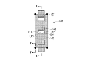
- the air guide member 100 includes a main body portion 105 that has a cylindrical shape centering on the rotation axis O, and an air guide member fin 106 formed on the outer peripheral surface of the main body portion 105. Have.
- the main body portion 105 is a radially chamfered portion of the center disk 80 of the inner ring 13Aa and the center disk 80 of the outer ring 13Ab, and a rotation axis provided on the wheel 29 so as to be sandwiched between the center disks 80.
- the main body portion 105 has an inner diameter such that the inner peripheral surface is located on the radially outer side than the radial position where the decorative hole 83 is formed, and the decorative hole 83 is formed from the radially outer side of the rotation axis O. Covering.
- the main body portion 105 is provided with rubber members 107 at positions corresponding to both end portions in the rotation axis O direction.
- the rubber member 107 prevents the main body portion 105 from dropping from the wheel 29.
- the rubber member 107 fills the gap between the wheel 29 and the main body 105 and suppresses the leakage of the airflow AR, thereby achieving an efficient flow.
- the rubber member 107 can be selected from various shapes corresponding to the difference in the shape of the wheel 29 (the shape varies depending on the manufacturer).
- the cross-sectional shape shown in FIG. 7C is a circular shape
- the cross-sectional shape shown in FIG. 7D is a one-side lip shape
- the cross-sectional shape shown in FIG. 7C is a circular shape
- the cross-sectional shape shown in FIG. 7D is a one-side lip shape
- a plurality of wind guide member fins 106 are formed on the outer peripheral surface of the main body portion 105 so as to be spaced apart from each other at equal intervals in the circumferential direction of the rotation axis O. More specifically, the air guide member fin 106 is directed toward one side in the circumferential direction of the rotation axis O (counterclockwise toward the plane of FIG. 7B, a white arrow) toward the outer side in the radial direction of the rotation axis O. It is inclined and extends.
- a through hole 108 penetrating the main body portion 105 is formed in a region on the outer peripheral surface of the main body portion 105 corresponding to a region where the wind guide member fins are provided on the inclined side of the wind guide member fin 106.
- the air guide member fins 106 and the through holes 108 corresponding to the air guide member fins 106 are integrally formed. That is, two sides L11 and L12 extending in the circumferential direction out of a quadrangle extending on one side in the circumferential direction of the rotation axis O when viewed from the outside in the radial direction of the rotation axis O, and the two sides L11 and L12. Is formed on one side L13 in the circumferential direction. Thereafter, by lifting these three sides radially outward, the through-hole 108 and the square air guide member fin 106 are formed.
- the air guide member fins 106 and the through holes 108 may be formed separately, and their shapes are not limited to the case of this embodiment.
- the air guide member 100 can guide the air flow AR so that the air does not flow toward the outside of the wheel 29.
- the air guide member 100 guides the airflow AR passing through the brake device 17, thereby While the brake device 17 is cooled by the AR, the air flow AR can be passed from the wheel 29 of the inner ring 13Aa to the wheel 29 of the outer ring 13Ab. Therefore, the entire traveling wheel 13A can be cooled, and the brake device 17 and the traveling wheel 13A can be efficiently cooled by the airflow AR generated by the cooling fins 96.
- Airflow AR can be generated.
- the air guide member fins 106 are inclined and extend toward the one side in the circumferential direction of the rotation axis O on the main body portion 105. Therefore, when the rotation direction of the wheel 29 coincides with one side of the circumferential direction, that is, when the direction of the white arrow in FIG. 7B is the rotation direction, the direction of the white arrow toward the through hole 108 Airflow AR occurs in As a result, an airflow AR is generated in the wheel 29 from the outside of the wheel 29 toward the inside.
- the air guide member 100 is not necessarily provided with the air guide member fins 106 and the through holes 108.
- a vehicle 1B according to a third embodiment of the present invention will be described.
- the same components as those in the first embodiment and the second embodiment are denoted by the same reference numerals, and detailed description thereof is omitted.
- the vehicle 1B of this embodiment is based on the second embodiment, and the air guide member 110 of the traveling carriage 2B is different from that of the second embodiment.
- the air guide member 110 has a tubular shape that surrounds the opening of each decoration hole 83 from the outer peripheral side.
- the air guide member 110 is provided so as to be sandwiched between a decoration hole 83 in the inner ring 13Aa and a decoration hole 83 in the outer ring 13Ab facing each other in the direction of the rotation axis O.
- the air guide member 110 is provided with members (not shown) similar to the rubber member 107 at positions corresponding to both ends of the rotation axis O, and when the air guide member 110 is sandwiched between the inner ring 13Aa and the outer ring 13Ab, The rubber member regulates the drop off from the wheel 29.
- the air guide member 110 is a tubular member that surrounds the opening of each decoration hole 83 from the outer peripheral side, so that the air flow AR generated by the cooling fins 96 is the air guide member 110.
- the cross-sectional area of the flow path of the airflow AR can be reduced. Therefore, the flow velocity of the airflow AR flowing through the air guide member 110 is increased, and the heat dissipation effect from the brake device 17 by the airflow AR passing through the brake device 17 can be improved.
- the direction in which the cooling fins 96 of the cooling device 18 extend may be formed so as to be the same in the circumferential direction between the left and right traveling wheels 13 across the subframe 11. That is, for example, the cooling fins 96 in all the traveling wheels 13 (13A) are placed in the rolling direction of the traveling wheels 13 (13A) when the vehicle 1 (1A, 1B) is traveling, or in the direction opposite to the rolling direction. It is formed to extend.
- the cooling device 18 on the pair of left and right wheels 29 in this way, the airflow AR generated by the cooling fins 96 on the wheels 29 of the pair of left and right traveling wheels 13 (13A) is close to each other. Or it distribute
- the direction in which the cooling fins 96 of the cooling device 18 extend may be formed to be different in the circumferential direction between the left and right traveling wheels 13 with the subframe 11 interposed therebetween. That is, for example, the cooling fin 96 extends in the rolling direction of the traveling wheel 13 (13A) when the vehicle 1 (1A, 1B) travels on the left traveling wheel 13 (13A), and the vehicle on the right traveling wheel 13 (13A). The cooling fin 96 extends in a direction opposite to the rolling direction of the traveling wheel 13 (13A) during traveling of 1 (1A, 1B).
- the air flow AR directed to one side (for example, from the left side to the right side) of the rotation axis O of the axle 12 is generated by the cooling fins 96 provided on each of the wheels 29 in the pair of left and right traveling wheels 13 (13A). become. Therefore, the air flow AR circulates in the same direction along the rotation axis O in all the wheels 29.
- the airflow AR generated on the pair of left and right traveling wheels 13 (13A) can be prevented from interfering with each other, and the flow of the airflow AR smoothly passing through the brake device 17 can be generated.
- the direction in which the cooling fins 96 of the cooling device 18 extend is not limited to the case described above, and can be selected as appropriate for each traveling wheel 13 (13A).
- the cooling device 18 is formed separately from the wheel 29, but may be formed integrally with the wheel 29.
- the cooling fin 96 generates an airflow AR in the direction along the rotational axis O of the axle 12, at least the airflow AR passing through the brake device 17 through the decoration hole 83 may be generated.
- the airflow AR does not have to be generated in the direction along the line.
- the airflow AR generated by the cooling fin 96 is passed through the inside and outside of the wheel 29 using the decoration hole 83.
- a ventilation hole that communicates the inside and outside of the wheel 29 may be separately formed in the wheel 29. .
- the air guide member 100 (110) in these embodiments is applicable even if a single tire or the like, and the tire quantity is It is not limited.
- the air flow AR from the cooling fin 96 can be guided to the brake disc 90 by providing the air guide member 100 (110) between the cooling fin 96 and the decoration hole 83.
- the brake device 17 is not limited to a disc brake.
- the cooling device 18 can be applied to cool the brake.
- the material of the plate-like member 95, the cooling fin 96, the air guide member 100 (110), and the air guide member fin 106 may be a metal material such as a steel material or an aluminum material, or a resin or hard rubber such as a fiber reinforced plastic.
- Non-metallic materials such as In the case where a metal material is used for the plate-like member 95, the cooling fin 96, the air guide member 100 (110), and the air guide member fin 106, a rubber member is used as a cushioning material in a portion in contact with the wheel 29 or the hub 28. Good.
- the vehicle 1 (1A, 1B) may be a vehicle of a central guide rail type (center guide type) transportation system in which a guide rail along the extending direction of the track 5 is provided at the center of the track 5 in the width direction. Good.
- the traveling carriage 2 (2A, 2B) has been described as a steering carriage.
- the traveling carriage 2 (2A, 2B) may be a normal bogie that is not steered, and is not limited to the above-described embodiment.
- the cooling performance of the brake device accommodated in the wheel can be maintained by the cooling fins of the cooling device regardless of the traveling direction, and the braking performance can be maintained.
Landscapes
- Engineering & Computer Science (AREA)
- Mechanical Engineering (AREA)
- Transportation (AREA)
- General Engineering & Computer Science (AREA)
- Braking Arrangements (AREA)
- Platform Screen Doors And Railroad Systems (AREA)
Abstract
内側にブレーキ装置(17)が配されて車軸(12)と一体に回転する走行輪(13)のホイール(29)に設けられ、ホイール(29)の正逆両方向への回転によってホイール(29)の内外を連通する通風孔を通じてブレーキ装置(17)を通過する気流(AR)を生じさせる冷却フィン(96)を備え、冷却フィン(96)は、上記通風孔として、ホイール(29)に車軸(12)の回転軸線(O)を中心とした円周上に複数形成された飾り孔(83)を通じて気流(AR)を生じさせる。
Description
本発明は車両に設けられるブレーキ装置を冷却する冷却装置、及びこれを備えた走行台車、車両に関する。
本願は、2013年11月20日に出願された特願2013-240385号に基づき優先権を主張し、その内容をここに援用する。
本願は、2013年11月20日に出願された特願2013-240385号に基づき優先権を主張し、その内容をここに援用する。
バスや鉄道以外の新たな交通手段として、ゴムタイヤの走行輪が設けられた走行台車によって軌道上を走行する軌道系交通システムが知られている。このような軌道系交通システムは、一般に新交通システムやAPM(Automated People Mover)と呼ばれている。
ここで、軌道系交通システムにおける車両の走行台車には、ディスクブレーキやドラムブレーキ等のブレーキ装置が設けられている。そして、ブレーキ装置は、走行輪におけるホイールのリムの内側に収容されている。このため、ブレーキ装置を使用した際の発熱を外部へ放熱することが難しく、ブレーキ性能が低下してしまうという問題がある。
ここで、特許文献1には、バスやトラック等に設けられたホイールのリムの内側にホイールの回転にともなって回転するファンを設け、リムの内側に強制的に空気を送り込んで、ブレーキ装置を冷却する放熱構造が記載されている。
しかしながら、バスやトラックでは、走行方向は基本的に一方向であるが、新交通システムの車両は、走行方向が前後に転換されて運行される。特許文献1に記載の放熱構造はバスやトラックに設けられるものであるため、前方向へ走行する際のホイールの回転によってリムの内側へ空気を送るようになっており、後方へ走行することは想定された構造となっていない。このため、単純にこの構造を軌道系交通システムの車両に適用したとしても、ホイールのリムの内側に設けられたブレーキ装置の冷却を十分に行うことができない。
本発明は、走行方向に関わらずホイールに収容されたブレーキ装置の冷却を行って、ブレーキ性能を維持できる冷却装置、及びこれを備えた走行台車、車両を提供することを目的とする。
本発明の第一の態様の冷却装置によれば、内側にブレーキ装置が配されて車軸と一体に回転する走行輪のホイールに設けられ、該ホイールの正逆両方向への回転によって前記ホイールの内外を連通する通風孔を通じて前記ブレーキ装置を通過する気流を生じさせる冷却フィンを備える。
このような冷却装置では、走行輪のホイールがいずれの方向へ回転したとしても、冷却フィンによってホイールの内側のブレーキ装置を通過する気流を生じさせることが可能となる。従って、このような走行輪が設けられて走行する車両では、走行方向が前後に転換されて走行する場合であってもブレーキ装置の冷却を行うことができる。
また、本発明の第二の態様に係る冷却装置では、第一の態様における前記冷却フィンは、前記通風孔として、前記ホイールに前記車軸の回転軸線を中心とした円周上に複数形成された飾り孔を通じて前記気流を生じさせてもよい。
ホイールに軽量化やホイール内外の通風を目的として形成された飾り孔を通じて、冷却フィンによる気流を生じさせることができる。よって、ホイール内外へ向かう気流を生じさせるために、ホイール内外を連通する通風孔を新たに形成する必要がなくなり、通風孔を新たに形成するためのコストを抑えることができる。
さらに、本発明の第三の態様に係る冷却装置では、第一又は二の態様における前記冷却フィンは、前記車軸の回転軸線に沿う方向への気流を生じさせてもよい。
このように回転軸線に沿う方向への気流を生じさせることで、気流をブレーキ装置へ直射することができ、ブレーキ装置の冷却効果を向上することができる。また、このような気流によってブレーキ装置からの発熱を回収した後の気流を、速やかにホイールから離間する方向に流通させて、効率的な排熱が可能となる。
また、本発明の第四の態様に係る冷却装置では、第一から第三のいずれかの態様における前記車軸と前記ホイールとを固定する該ホイールのハブにおける前記車軸と離間する側の端部に設けられて前記車軸とともに回転する板状部材を備え、前記冷却フィンは、前記板状部材に形成されていてもよい。
このような板状部材をホイールに設けられたハブに取り付けることで、ブレーキ装置を通過する気流を生じさせる冷却フィンを容易に設置することができる。
さらに、本発明の第五の態様に係る冷却装置では、第四の態様における前記冷却フィンは、前記板状部材上で前記車軸の回転軸線を中心とした円周上に複数形成され、各々の前記冷却フィンは、前記板状部材上から前記回転軸線の方向に、前記車軸から離間する側に向かうに従って該回転軸線の周方向の一方側に向かって傾斜して延び、かつ、前記冷却フィンの傾斜する側で該冷却フィンが設けられた領域に対応する前記板状部材上の領域には、該板状部材を貫通する貫通孔が形成されていてもよい。
このように、冷却フィンが回転軸線の周方向の一方側に向かって傾斜して延びていることで、ホイールの回転方向が周方向の一方側に一致している場合、即ち冷却フィンが延びる方向にホイールが回転する場合には、ホイールの外側から内側へ向かう気流が生じる。
一方で、ホイールの回転方向が周方向の他方側に一致している場合、即ち冷却フィンが延びる方向とは逆方向にホイールが回転する場合にはホイールの内側から外側へ向かう気流が生じる。従って、ホイールの回転方向が正逆いずれの場合であっても、ブレーキ装置を通過する気流を生じさせることが可能となる。
一方で、ホイールの回転方向が周方向の他方側に一致している場合、即ち冷却フィンが延びる方向とは逆方向にホイールが回転する場合にはホイールの内側から外側へ向かう気流が生じる。従って、ホイールの回転方向が正逆いずれの場合であっても、ブレーキ装置を通過する気流を生じさせることが可能となる。
また、本発明の第六の態様に係る冷却装置は、第一から第五のいずれかの態様における前記ホイールに設けられて該ホイールと一体に回転し、前記冷却フィンからの前記気流を前記通風孔に導く導風部材をさらに備えていてもよい。
このような導風部材によって、ホイールの外側から内側へ向かう気流が冷却フィンによって生じさせられた際には、ホイールの気流がブレーキ装置へ導かれる前にホイールの外部へ向かう流れとならないように気流を案内することができる。また、ホイールの内側から外側へ向かう気流が冷却フィンによって生じさせられた際には、気流によってブレーキ装置の冷却を行うとともに気流をホイールの内側から外側へと、ホイールを通過させることができるため、走行輪全体の冷却が可能となる。従って、冷却フィンによる気流によってブレーキ装置、及び走行輪の効率的な冷却が可能となる。
さらに、本発明の第七の態様に係る冷却装置では、第六の態様における前記導風部材は、前記通風孔を前記車軸の回転軸線の径方向外側から覆う該回転軸線を中心とした筒状をなしていてもよい。
このような筒状をなす導風部材によって、ホイールに導風部材を容易に設置して気流を通風口に案内することができ、冷却フィンによって生じた気流によって効率的にブレーキ装置の冷却が可能となる。
また、本発明の第八の態様に係る冷却装置では、第七の態様における前記導風部材は、前記車軸の回転軸線を中心とした筒状をなす本体部と、前記本体部の外周面上から前記車軸の回転軸線の径方向外側に向かうに従って該回転軸線の周方向の一方側に向かって傾斜して延びる導風部材フィンと、を有し、前記導風部材フィンの傾斜する側で該導風部材フィンが設けられた領域に対応する前記本体部の外周面上の領域には、該本体部を貫通する貫通孔が形成されていてもよい。
このように導風部材フィンが回転軸線の周方向の一方側に向かって傾斜して延びていることで、ホイールの回転方向が周方向の一方側に一致している場合、即ち導風部材フィンが延びる方向にホイールが回転する場合には、ホイールの外側から内側へ回転軸線の径方向へ向かう気流が生じる。一方で、ホイールの回転方向が周方向の他方側に一致している場合、即ち冷却フィンが延びる方向とは逆方向にホイールが回転する場合にはホイールの内側から外側へ回転軸線の径方向へ向かう気流が生じる。従って、ホイールの回転方向が正逆いずれの場合であっても、単に冷却フィンによる気流を本体部によって案内するだけでなく導風部材フィンによって径方向に沿う気流を生じさせ、より多くの気流をブレーキ装置に通過させることができる。よって、さらに効率的なブレーキ装置の冷却が可能となる。
さらに、本発明の第九の態様に係る冷却装置では、第六の態様における前記導風部材は、前記通風孔の開口部を外周側から囲む管状をなしていてもよい。
このように導風部材を通風孔の開口部を外周側から囲む管状の部材とすることで、導風部材を流通する気流の流路断面積を小さくすることができる。従って、導風部材を流通する気流の流速が大きくなり、ブレーキ装置を通過する気流による放熱効果を向上することができる。
また、本発明の第十の態様に係る冷却装置では、第六から第九のいずれかの態様における前記導風部材には、前記回転軸線方向の端部となる前記ホイールとの間にゴム部材が設けられていてもよい。
このようなゴム部材によって、ホイールとは別体で導風部材を設けた場合に、ホイールと導風部材との密着性を高め、ホイールからの導風部材の脱落を規制することができる。
また、導風部材とホイールとの間の隙間を埋め、導風部材とホイールとの間の気流の漏れを抑制することができ、より多くの気流を、ブレーキ装置へ送ることができる。
また、導風部材とホイールとの間の隙間を埋め、導風部材とホイールとの間の気流の漏れを抑制することができ、より多くの気流を、ブレーキ装置へ送ることができる。
また、本発明の第十一の態様に係る走行台車は、回転軸線を中心として回転する車軸と、ホイールを有して前記車軸と一体に回転する左右一対の走行輪と、前記一対の走行輪を支持するとともに軌道に沿って延在する案内レールに案内される案内装置と、前記ホイールに設けられた第一から第十のいずれかの態様における冷却装置と、を備える。
このような走行台車によれば、冷却装置を備えることで、走行輪のホイールがいずれの方向へ回転したとしても、冷却フィンによってホイールの内側のブレーキ装置を通過する気流を生じさせることが可能となる。従って、走行台車の走行方向が前後に転換されて走行する場合であってもブレーキ装置の冷却が可能となる。
さらに、本発明の第十二の態様に係る走行台車では、第十一の態様に係る前記一対の走行輪における前記ホイール各々に設けられた前記冷却装置では、これら冷却装置で共に前記ホイールから前記車軸に向かう気流を生じさせるか、又は、共に前記車軸から前記ホイールに向かう気流を生じさせるように前記冷却フィンが設けられていてもよい。
このように、左右一対の走行輪のホイールで冷却フィンによって生じさせられた気流は、互いに近接するように、又は、互いに離間するように流通することになる。この結果、左右一対に生じた気流の力は互いに打消し合い、走行台車の走行への気流の影響を低減することができる。
また、本発明の第十三の態様に係る走行台車では、第十一の態様に係る前記一対の走行輪における前記ホイール各々に設けられた前記冷却装置では、これら冷却装置で共に前記車軸の回転軸線の方向の一方側に向かう気流を生じさせるような前記冷却フィンが設けられていてもよい。
このように、左右一対の走行輪のホイールで冷却フィンによって生じさせられた気流は、同じ方向に向かって流通することになる。従って、左右一対に生じた気流が互いに干渉し合うことを抑制でき、ブレーキ装置をスムーズに通過する気流の流れを生じさせることができる。
さらに、本発明の第十四の態様に係る車両は、内部に空間が形成された車体と、前記車体の下部に設けられた第十一から第十三のいずれかの態様の走行台車と、を備える。
このような車両によれば、冷却装置を備える走行台車が設けられていることで、走行輪のホイールがいずれの方向へ回転したとしても、冷却フィンによってホイールの内側のブレーキ装置を通過する気流を生じさせることが可能となる。従って、車両の走行方向が前後に転換されて走行する場合であってもブレーキ装置の冷却が可能となる。
上記の冷却装置、走行台車、および車両によると、冷却装置の冷却フィンによって、走行方向に関わらずホイールに収容されたブレーキ装置の冷却を行って、ブレーキ性能を維持可能となる。
〔第一実施形態〕
以下、本発明の第一実施形態に係る車両1について、図面を参照して詳細に説明する。
図1~図3に示すように、車両1は、軌道5に設けられた案内レール6によって案内されながら軌道5上を走行する軌道系交通システムの車両である。本実施形態において、車両1は、軌道5の幅方向両側に、軌道5の延在方向に沿って延びる案内レール6が設けられた側方案内軌条式(サイドガイド方式)の交通システムの車両である。
以下、本発明の第一実施形態に係る車両1について、図面を参照して詳細に説明する。
図1~図3に示すように、車両1は、軌道5に設けられた案内レール6によって案内されながら軌道5上を走行する軌道系交通システムの車両である。本実施形態において、車両1は、軌道5の幅方向両側に、軌道5の延在方向に沿って延びる案内レール6が設けられた側方案内軌条式(サイドガイド方式)の交通システムの車両である。
<車両>
車両1は、軌道5上を走行する走行台車2と、走行台車2に支持された車体3(図1参照)とを備えている。
以下の説明における前後上下左右等の向きは、特に記載が無ければ車両1の向きと同一とする。また、以下では、車両1の前後方向に沿う矢印DI方向を前方、矢印DI方向と逆方向を後方とする。さらに、左右方向となる幅方向のうち、走行台車2の中央部に配置された後述するサブフレーム11に向かう方向を幅方向内側といい、サブフレーム11から離間する方向を幅方向外側という。
車両1は、軌道5上を走行する走行台車2と、走行台車2に支持された車体3(図1参照)とを備えている。
以下の説明における前後上下左右等の向きは、特に記載が無ければ車両1の向きと同一とする。また、以下では、車両1の前後方向に沿う矢印DI方向を前方、矢印DI方向と逆方向を後方とする。さらに、左右方向となる幅方向のうち、走行台車2の中央部に配置された後述するサブフレーム11に向かう方向を幅方向内側といい、サブフレーム11から離間する方向を幅方向外側という。
図1に示すように、車体3は、前後方向に長い直方体形状を呈し、その内部に乗客を収容可能な空間が形成されている。車体3の下部の前後に、上述した走行台車2が一対で設けられている(不図示)。前側の走行台車2と後側の走行台車2とは、前後の向きが逆であること以外は同一構成であるため、以下では代表して一方(前側)の走行台車2について説明する。
<走行台車>
図1から図5Bに示すように、走行台車2は、幅方向の中央部に配設されたサブフレーム11と、サブフレーム11に回転可能に支持された左右一対の車軸12(図2参照)と、各車軸12に連結された走行輪13とを備えている。
この走行台車2は、案内レール6に案内される案内装置14と、案内装置14の変位に応じて走行輪13を操舵する操舵機構15(図1参照)と、車体3の台枠3aと走行輪13との間に配置された懸架装置16とを備えている。
走行台車2は、走行輪13に設けられたブレーキ装置17と、ブレーキ装置17を冷却する冷却装置18とを備えている。
図1から図5Bに示すように、走行台車2は、幅方向の中央部に配設されたサブフレーム11と、サブフレーム11に回転可能に支持された左右一対の車軸12(図2参照)と、各車軸12に連結された走行輪13とを備えている。
この走行台車2は、案内レール6に案内される案内装置14と、案内装置14の変位に応じて走行輪13を操舵する操舵機構15(図1参照)と、車体3の台枠3aと走行輪13との間に配置された懸架装置16とを備えている。
走行台車2は、走行輪13に設けられたブレーキ装置17と、ブレーキ装置17を冷却する冷却装置18とを備えている。
サブフレーム11の内部には、図示しないモータ等の駆動源からの回転動力を車軸12に伝達するための、ディファレンシャルギヤ等の図示しない減速機構が収容されている。
図2に示すように、各車軸12は、幅方向に沿って延在しており、その幅方向内側の端部が首振り可能なジョイント23を介してサブフレーム11内の減速機構に連結されている。即ち、減速機構を介して駆動源から伝達された回転動力が、車軸12に分配されて各車軸12が回転軸線Oを中心として回転する。
各車軸12における幅方向外側の端部は、首振り可能なジョイント24を介して走行輪13を取り付ける走行輪取付軸27に連結されている。走行輪取付軸27は回転軸線Oを中心として車軸12とともに回転する。各走行輪取付軸27は、上下方向に沿って延在するキングピン26(図1参照)回りに揺動可能となっている。
即ち、キングピン26は、走行輪13の操舵軸としての機能を有している。
即ち、キングピン26は、走行輪13の操舵軸としての機能を有している。
(懸架装置)
図2に示すように、懸架装置16は、上述した各走行輪13をサブフレーム11に対して独立して上下方向に変位可能に支持する第一懸架機構51と、台枠3aに対してサブフレーム11を上下方向に変位可能に支持する第二懸架機構52(図3参照)と、上述した台枠3aと第一懸架機構51との間に配置された左右一対の空気ばね53とを備えている。
図2に示すように、懸架装置16は、上述した各走行輪13をサブフレーム11に対して独立して上下方向に変位可能に支持する第一懸架機構51と、台枠3aに対してサブフレーム11を上下方向に変位可能に支持する第二懸架機構52(図3参照)と、上述した台枠3aと第一懸架機構51との間に配置された左右一対の空気ばね53とを備えている。
第一懸架機構51は、いわゆるダブルウィッシュボーン方式の独立懸架機構である。この第一懸架機構51は、幅方向に沿って延びるアッパアーム61及びロアアーム62を左右一対で備えている。
アッパアーム61は、上方から見た平面視でH字状とされ、幅方向の両端部が中央部に対してそれぞれ二股に分岐している。アッパアーム61のうち、幅方向内側の端部はサブフレーム11にピン結合され、外側の端部は上述したキングピン26にピン結合されている。
アッパアーム61は、上方から見た平面視でH字状とされ、幅方向の両端部が中央部に対してそれぞれ二股に分岐している。アッパアーム61のうち、幅方向内側の端部はサブフレーム11にピン結合され、外側の端部は上述したキングピン26にピン結合されている。
ロアアーム62は、上方から見た平面視でH字状とされ、幅方向の両端部が中央部に対してそれぞれ二股に分岐している。ロアアーム62のうち、幅方向内側の端部はサブフレーム11においてアッパアーム61よりも下方でピン結合され、外側端部は上述したキングピン26においてアッパアーム61よりも下方でピン結合されている。
第一懸架機構51は、軌道5の凹凸によって走行輪13が上下方向に変位した際、走行輪13及びサブフレーム11に対して上下方向に揺動可能とされている。
第一懸架機構51は、軌道5の凹凸によって走行輪13が上下方向に変位した際、走行輪13及びサブフレーム11に対して上下方向に揺動可能とされている。
図3に示すように、第二懸架機構52は、いわゆる平行リンク機構であって、互いに平行に延びる上リンク71及び下リンク72を左右一対で備えている。
各上リンク71及び下リンク72は、後方に向かうに従い上方に向けて傾斜して延在しており、その後端部が台枠3aから下方に延設された懸架枠73にそれぞれピン結合されている。一方、上リンク71及び下リンク72の前端部は、サブフレーム11の後端部にピン結合されている。
各上リンク71及び下リンク72は、後方に向かうに従い上方に向けて傾斜して延在しており、その後端部が台枠3aから下方に延設された懸架枠73にそれぞれピン結合されている。一方、上リンク71及び下リンク72の前端部は、サブフレーム11の後端部にピン結合されている。
第二懸架機構52は、懸架枠73とサブフレーム11との上下方向に沿う相対移動に応じて、懸架枠73及びサブフレーム11に対して上下方向に揺動可能とされている。第二懸架機構52は、走行輪13の駆動力や制動力を車体3に伝えるための牽引ロッドとしての機能も有している。
空気ばね53は、その上端部が台枠3aに取り付けられ、その下端部が各アッパアーム61の上面に各別に取り付けられている。空気ばね53は、車体3に対する走行輪13の相対的な上下振動を緩和する。
(案内装置)
案内装置14は、案内枠31と、案内枠31をサブフレーム11に連結するための案内枠支持機構32と、案内枠31に回転可能に支持された案内輪33と、を備えている。
案内装置14は、案内枠31と、案内枠31をサブフレーム11に連結するための案内枠支持機構32と、案内枠31に回転可能に支持された案内輪33と、を備えている。
案内枠31は、上下方向から見た平面視で井桁状に組み込まれたものであって、サブフレーム11の下方に配置されている。具体的に、案内枠31は、前後方向に沿って延びる左右一対の縦梁34と、これら縦梁34の前後方向に沿う両端部に連結されるとともに、幅方向に沿って延びる一対の横梁35とを備えている。
縦梁34は、前後方向の両端部が走行輪13よりも幅方向外側に位置しており、走行輪13よりも幅方向外側に横梁35がそれぞれ連結されている。
各横梁35は、幅方向の両端部が各走行輪13よりも幅方向外側に位置しており、走行輪13を前後方向の両側から挟むように配置されている。各横梁35の幅方向の両端部には、案内輪33が一つずつ取り付けられている。
各横梁35は、幅方向の両端部が各走行輪13よりも幅方向外側に位置しており、走行輪13を前後方向の両側から挟むように配置されている。各横梁35の幅方向の両端部には、案内輪33が一つずつ取り付けられている。
案内輪33は、上下方向に沿って延びる回転軸O1回りに回転可能に支持されており、案内レール6に接することで転動する。
案内枠31には案内輪33の下方で分岐案内輪36が設けられており、軌道5における分岐部で、軌道5に設けられた不図示の分岐案内レールに接して転動し、車両1を分岐方向へと案内する。
案内枠31には案内輪33の下方で分岐案内輪36が設けられており、軌道5における分岐部で、軌道5に設けられた不図示の分岐案内レールに接して転動し、車両1を分岐方向へと案内する。
図2及び図3に示すように、案内枠支持機構32はサブフレーム11の下方に配置されている。案内枠支持機構32の幅方向外側の端部が第一懸架機構51(各アーム61、62)の幅方向外側の端部よりも幅方向内側に位置している。案内枠支持機構32は旋回軸受43を有している。この旋回軸受43によって、サブフレーム11に対して案内枠31を上下方向に沿って延びる旋回軸O2周りに旋回可能に支持している。
具体的には、旋回軸受43は、外側輪及び内側輪から構成され、外側輪及び内側輪のいずれか一方が案内枠支持機構32に固定され、他方が案内枠31に固定されている。図示の例では、旋回軸O2は、案内枠31の前後及び左右の中央部に位置している。
具体的には、旋回軸受43は、外側輪及び内側輪から構成され、外側輪及び内側輪のいずれか一方が案内枠支持機構32に固定され、他方が案内枠31に固定されている。図示の例では、旋回軸O2は、案内枠31の前後及び左右の中央部に位置している。
(操舵機構)
図1に示すように、操舵機構15は、旋回軸O2周りの案内枠31の旋回に連動して、走行輪13の操舵角を変えるものである。この操舵機構15は、各キングピン26を基準にして走行輪13(走行輪取付軸27)と一体的に揺動するステアリングアーム41と、各ステアリングアーム41と案内枠31とを各別に連結するステアリングロッド42と、を有している。
図1に示すように、操舵機構15は、旋回軸O2周りの案内枠31の旋回に連動して、走行輪13の操舵角を変えるものである。この操舵機構15は、各キングピン26を基準にして走行輪13(走行輪取付軸27)と一体的に揺動するステアリングアーム41と、各ステアリングアーム41と案内枠31とを各別に連結するステアリングロッド42と、を有している。
ステアリングロッド42は、幅方向に沿って延在する。ステアリングロッド42の幅方向外側の端部はステアリングアーム41の前端部にピン結合され、幅方向内側の端部は案内枠31にピン結合されている。
(走行輪)
走行輪13は、各走行輪取付軸27を介して車軸12に一つずつ取り付けられたシングルタイヤである。この走行輪13は、走行輪取付軸27に取り付けられた有底筒状をなすホイール29と、ホイール29を覆うゴムタイヤ30とを有している。
走行輪13は、各走行輪取付軸27を介して車軸12に一つずつ取り付けられたシングルタイヤである。この走行輪13は、走行輪取付軸27に取り付けられた有底筒状をなすホイール29と、ホイール29を覆うゴムタイヤ30とを有している。
ゴムタイヤ30は、例えば内部に中子が収納された中子式のもの用いてもよく、一般のトラックやバス等に用いられる中子なしのものを用いても構わない。
図4A及び図4Bに示すように、ホイール29は、最も幅方向外側に位置する円板状をなすセンターディスク80と、この端面の径方向外側の端縁から幅方向内側に延びるように形成された筒状をなすリム81と、走行輪取付軸27を介して車軸12とホイール29とを固定するハブ28とを有している。
センターディスク80の中心部は回転軸線Oに一致しており、この中心部には回転軸線Oを中心とした挿入孔82が形成されている。さらに、このセンターディスク80には、挿入孔82よりも径方向外側の位置に、回転軸線Oを中心とした円周上にボルト取付孔84が複数形成されている。
センターディスク80には、ボルト取付孔84よりも回転軸線Oの径方向外側の位置に、ホイール29の内外を連通する通風孔として、回転軸線Oを中心とした円周上に飾り孔83が複数形成されている。
飾り孔83は、ホイール29の軽量化やホイール29における幅方向内外の間の通風性を向上させる目的で設けられている。本実施形態では、この飾り孔83は回転軸線Oの径方向外側の端部位置に形成されている。また各々の飾り孔83は、幅方向外側から内側に向かうに従って、回転軸線Oの径方向外側から内側に向かって傾斜して形成されている。
本実施形態では、センターディスク80は、径方向外側の端縁部分で面取りがされたような形状となっている。これにより、飾り孔83の幅方向外側の開口部は回転軸線Oに対して傾斜して、径方向外側に向いて開口している。
本実施形態では、センターディスク80は、径方向外側の端縁部分で面取りがされたような形状となっている。これにより、飾り孔83の幅方向外側の開口部は回転軸線Oに対して傾斜して、径方向外側に向いて開口している。
ハブ28は走行輪取付軸27の幅方向外側の端部に取り付けられており、かつセンターディスク80の挿入孔82に挿入され、センターディスク80のボルト取付孔84にボルト85(図2参照)が挿通されることでセンターディスク80に固定される。
ここで、挿入孔82にハブ28が挿入された状態では、ハブ28の先端がセンターディスク80から幅方向外側に突出した状態となる。
ここで、挿入孔82にハブ28が挿入された状態では、ハブ28の先端がセンターディスク80から幅方向外側に突出した状態となる。
(ブレーキ装置)
図1及び図2に示すように、ブレーキ装置17は、ホイール29におけるリム81の内側、即ちセンターディスク80よりも幅方向内側に配されている。ブレーキ装置17は、ホイール29のハブ28に固定されたブレーキディスク90と、ブレーキディスク90を回転軸線Oの両側から挟持可能なブレーキパッド(不図示)を備えるブレーキキャリパ91とを有している。
図1及び図2に示すように、ブレーキ装置17は、ホイール29におけるリム81の内側、即ちセンターディスク80よりも幅方向内側に配されている。ブレーキ装置17は、ホイール29のハブ28に固定されたブレーキディスク90と、ブレーキディスク90を回転軸線Oの両側から挟持可能なブレーキパッド(不図示)を備えるブレーキキャリパ91とを有している。
即ち、本実施形態のブレーキ装置17はディスクブレーキである。ブレーキキャリパ91における上記ブレーキパッドが、ブレーキディスク90を油圧や空圧によって挟持することで走行輪13に制動力を付与可能である。
(冷却装置)
冷却装置18は、ホイール29のセンターディスク80から幅方向外側に突出したハブ28の外側端部に設けられた板状部材95と、板状部材95に形成されて、飾り孔83を通じてブレーキ装置17を通過する気流ARを生じさせる冷却フィン96とを備えている。
冷却装置18は、ホイール29のセンターディスク80から幅方向外側に突出したハブ28の外側端部に設けられた板状部材95と、板状部材95に形成されて、飾り孔83を通じてブレーキ装置17を通過する気流ARを生じさせる冷却フィン96とを備えている。
図1、図2、図5A、及び図5Bに示すように、板状部材95は円板状に形成されており、中心が回転軸線Oに一致した状態でハブ28に固定されている。即ち、この板状部材95には回転軸線Oを中心とした円周上にボルト取付孔98が形成されている。このボルト取付孔98にボルト99(図2参照)が挿通されることで、板状部材95がハブ28に固定されている。
本実施形態では、ボルト取付孔98が形成された位置よりも回転軸線Oの径方向外側の領域は、板状部材95がハブ28に取り付けられた際に、ホイール29のセンターディスク80とハブ28とを固定した際のボルト85のボルト頭に板状部材95が干渉しないように、環状に外側に突出した環状突出部95aが形成されている。
冷却フィン96は、板状部材95の環状突出部95a上で、回転軸線Oを中心とした円周上に互いに周方向に等間隔で離間して複数形成されている。
各々の冷却フィン96は、環状突出部95a上から幅方向外側に向かって形成されている。より具体的には、回転軸線Oの方向に車軸12から離間する側に向かうに従って回転軸線Oの周方向の一方側(図5Aの紙面に向かって反時計回りの方向側、白抜き矢印の方向)に向かって傾斜して延びている。
この冷却フィン96の傾斜する側で冷却フィン96が設けられた領域に対応する環状突出部95a上の領域には、環状突出部95aを回転軸線Oの方向に貫通する貫通孔97が形成されている。
冷却フィン96及び貫通孔97は、ホイール29のセンターディスク80に飾り孔83が形成された径方向の位置に対応する位置に形成されている。これによって、ホイール29とともに板状部材95が正逆両方向へ回転した際には、飾り孔83を通じて外気を吸い込むか、又は吐き出すかのいずれかによって、回転軸線Oに沿う方向への気流ARを生じさせる。
ここで、本実施形態では、これら冷却フィン96、及び、各冷却フィン96に対応する貫通孔97は一体で形成されている。即ち、環状突出部95aに、回転軸線O方向から見て回転軸線Oの周方向の一方側に頂点Pが位置する三角形のうちの、頂点Pを挟む二つの辺L1、L2分の切り込みを形成する。その後、頂点P及び二つの辺L1、L2を環状突出部95aの表面から持ち上げることで、貫通孔97と三角形状をなす冷却フィン96とが形成されている。
冷却フィン96と貫通孔97は別々に形成してもよいし、これらの形状も本実施形態の場合に限定されない。
このような車両1によると、車両1の走行にともなって走行輪13のホイール29がいずれの方向へ回転したとしても、冷却装置18の冷却フィン96によって、ホイール29のリム81の内側のブレーキ装置17を通過する気流ARを生じさせることが可能となる。
より具体的には、冷却フィン96は板状部材95上で回転軸線Oの周方向の一方側に向かって傾斜して延びている。このため、ホイール29の回転方向が周方向の一方側に一致している場合、即ち図5Aの白抜き矢印の方向が回転方向である場合には、貫通孔97に向かう白抜き矢印の方向に気流ARが生じる。これによって、ホイール29には、ホイール29の外側から内側へ向かう気流ARが生じる。
一方で、ホイール29の回転方向が周方向の他方側に一致している場合、即ち図5Aの太矢印の方向が回転方向である場合には、貫通孔97から板状部材95の外部へ向かう太矢印の方向に気流ARが生じる。これによって、ホイール29には、ホイール29の内側から外側へ向かう気流ARが生じる。
従って、ホイール29の回転方向が正逆いずれの場合であっても、ブレーキ装置17を通過する気流ARを生じさせることが可能となる。よって、このようなホイール29を有する走行輪13が設けられて走行する本実施形態の車両1では、走行方向が転換されて走行する場合であってもブレーキ装置17の冷却が可能となる。
このようにブレーキ装置17の冷却を行うことでブレーキ装置17からの熱がホイール29を通じてゴムタイヤ30へ伝達される伝熱量を低減でき、ゴムタイヤ30の寿命を縮めてしまうことを抑制できる。
ブレーキディスク90の冷却によって、熱応力発生によるブレーキディスク90での亀裂発生を抑制できるため、ブレーキ装置17の耐久性向上が可能となる。油圧ブレーキを用いた場合にはブレーキオイルの過熱を抑制することができるため、ベーパーロックの発生を抑えることが可能となる。
ブレーキキャリパ91の冷却によって、ブレーキキャリパ91に設けられたブレーキパッドの寿命を延すことができる。
また、ブレーキ装置17の熱がハブ28に伝達される伝熱量を低減することができ、走行輪13を支持するベアリング等(不図示)の焼き付きを抑制でき、走行輪13の回転性能を維持することができる。
また、車両1には走行輪13へ制動力を付与する装置として回生ブレーキが設けられているが、回生失効が生じた後でもブレーキ装置17を用いることでブレーキ性能を損なうことなく走行可能であるため、引き続き高速走行が可能となる。よって定常運行に支障を来すことがなく、信頼性向上につながる。
冷却フィン96は、車軸12の回転軸線Oに沿う方向への気流ARを生じさせるように設けられている。このため、気流ARをブレーキ装置17へ直射することができ、ブレーキ装置17の冷却効果を向上することができる。また、このような気流ARによって、ブレーキ装置17からの発熱を回収した後の気流ARを速やかにホイール29から離間する方向に流通させ、効率的な排熱が可能となる。
冷却フィン96が形成された板状部材95をハブ28に取り付けることで、冷却フィン96をホイール29に容易に設けることができる。
ホイール29に軽量化やホイール29内外の通風を目的として予め形成された飾り孔83を通じて冷却フィン96によって気流ARを生じさせることができる。よって、ホイール29の内外へ向かう気流ARを生じさせるためにホイール29内外を連通する通風孔を新たに形成する必要がなくなり、通風孔を新たに形成するためのコストを抑えることができる。
本実施形態の車両1によると、冷却装置18の冷却フィン96によって、車両1の走行方向に関わらず、ホイール29に収容されたブレーキ装置17の冷却を行ってブレーキ性能を維持可能となる。
板状部材95は、円板状でなくともよい。また、板状部材95における環状突出部95aはボルト85との位置関係によっては、必ずしも形成されていなくともよい。
〔第二実施形態〕
次に、本発明の第二実施形態に係る車両1Aについて説明する。
第一実施形態と同様の構成要素には同一の符号を付して詳細説明を省略する。
本実施形態の車両では、走行台車2Aが第一実施形態とは異なっている。
次に、本発明の第二実施形態に係る車両1Aについて説明する。
第一実施形態と同様の構成要素には同一の符号を付して詳細説明を省略する。
本実施形態の車両では、走行台車2Aが第一実施形態とは異なっている。
図6に示すように、走行台車2Aは、各々の車軸12の端部に二つずつ、走行輪取付軸27を介して連結された走行輪13Aを備えている。即ち、本実施形態ではダブルタイヤの走行台車2Aである。
各々の車軸12に連結された走行輪13Aのうち、幅方向内側に位置する走行輪13Aを内輪13Aaとし、幅方向外側に位置する走行輪を外輪13Abとする。
内輪13Aaは、第一実施形態の走行輪13と同様の構成である。
外輪13Abは、内輪13Aaと同じものであるが、13Aa内輪を幅方向内外を逆転して配置することで、外輪13Abのセンターディスク80を内輪13Aaのセンターディスク80に突き合わせた状態で内輪13Aaに固定されている。これにより、内輪13Aaにおける飾り孔83と外輪13Abにおける飾り孔83とが、回転軸線Oの方向、即ち幅方向に対向して配置されている。
さらに、走行台車2Aは、冷却フィン96と飾り孔83との間に配置されて、冷却フィン96からの気流ARを飾り孔83に導く導風部材100を備えている。
図7A、図7Bに示すように、導風部材100は、回転軸線Oを中心とした筒状をなす本体部105と、本体部105の外周面上に形成された導風部材フィン106とを有している。
本体部105は、内輪13Aaのセンターディスク80と外輪13Abのセンターディスク80とにおける径方向外側の面取りがされた部分で、センターディスク80同士の間に挟み込まれるようにホイール29に設けられた回転軸線Oを中心とした筒状をなす部材である。
この本体部105は、内周面が飾り孔83が形成された径方向の位置よりも径方向外側に位置するような内径寸法となっており、飾り孔83を回転軸線Oの径方向外側から覆っている。
本体部105には、回転軸線O方向の両端部となる位置でゴム部材107が設けられている。内輪13Aaと外輪13Abとの間に本体部105を挟み込んだ際に、このゴム部材107によって、本体部105のホイール29からの脱落が規制される。
このゴム部材107により、ホイール29と本体部105の合せ部の隙間を埋め、気流ARの漏れを抑制し、効率的な流れとしている。
このゴム部材107により、ホイール29と本体部105の合せ部の隙間を埋め、気流ARの漏れを抑制し、効率的な流れとしている。
ゴム部材107は、ホイール29の形状の違い(メーカーにより形状は違ってくる)に対応して様々な形状のものを選択可能である。例えば、図7Cに示す断面形状が円形状のもの、図7Dに示す断面形状が片側リップ形状のもの、また、図7Eに示す断面形状が両側リップ形状のもの等が挙げられる。
導風部材フィン106は、本体部105の外周面上に、互いに回転軸線Oの周方向に等間隔で離間して複数形成されている。より具体的には、導風部材フィン106は、回転軸線Oの径方向外側に向かうに従って回転軸線Oの周方向の一方側(図7Bの紙面に向かって反時計回り、白抜き矢印)に向かって傾斜して延びている。
導風部材フィン106の傾斜する側で導風部材フィンが設けられた領域に対応する本体部105の外周面上の領域には、本体部105を貫通する貫通孔108が形成されている。
本実施形態では、これら導風部材フィン106、及び、各導風部材フィン106に対応する貫通孔108は一体で形成されている。即ち、本体部105に回転軸線Oの径方向外側から見て回転軸線Oの周方向の一方側に延びる四角形のうちの周方向に延びる二つの辺L11、L12と、これら二つの辺L11、L12を周方向一方側で接続する一つの辺L13の切り込みを形成する。その後、これら三つの辺を径方向外側に持ち上げることで、貫通孔108と四角形状をなす導風部材フィン106とが形成されている。
導風部材フィン106と貫通孔108は別々に形成してもよいし、これらの形状も本実施形態の場合に限定されない。
本実施形態の車両1Aによると、外輪13Abの幅方向外側から内輪13Aaの幅方向内側へ向かう気流ARが冷却フィン96によって生じさせられた際には、この気流ARがブレーキ装置17へ導かれる前にホイール29の外部へ向かう流れとならないように、導風部材100が気流ARを案内することができる。
内輪13Aaの幅方向内側から外輪13Abの幅方向外側へ向かう気流ARが冷却フィン96によって生じさせられた際には、ブレーキ装置17を通過する気流ARを導風部材100が案内することで、気流ARによってブレーキ装置17の冷却を行うとともに、気流ARを内輪13Aaのホイール29から外輪13Abのホイール29へと通過させることができる。このため、走行輪13A全体の冷却が可能となり、冷却フィン96による気流ARによってブレーキ装置17、及び走行輪13Aの効率的な冷却が可能となる。
筒状をなす導風部材100によって、ホイール29へ導風部材100を容易に設置することができる。
導風部材フィン106によって、ホイール29とともに導風部材100が正逆両方向へ回転した際には、貫通孔108から外気を吸い込むか、又は吐き出すかのいずれかによって、回転軸線Oの径方向に沿う気流ARを生じさせることができる。
より具体的には、導風部材フィン106が本体部105上で、回転軸線Oの周方向の一方側に向かって傾斜して延びている。このため、ホイール29の回転方向が周方向の一方側に一致している場合、即ち、図7Bの白抜き矢印の方向が回転方向である場合には、貫通孔108に向かう白抜き矢印の方向に気流ARが生じる。これによって、ホイール29には、ホイール29の外側から内部側へ向かう気流ARが生じる。
一方で、ホイール29の回転方向が周方向の他方側に一致している場合、即ち、図7Bの太矢印の方向が回転方向である場合には、貫通孔108から本体部105の外部へ向かう太矢印の方向に気流ARが生じる。これによって、ホイール29には、ホイール29の内側から外側へ向かう気流ARが生じる。
従って、ホイール29の回転方向が正逆いずれの場合であっても、単に冷却フィン96による気流ARを本体部105によって案内するだけでなく、導風部材フィン106によって径方向に沿う気流ARを生じさせることで、より多くの気流ARをブレーキ装置17に通過させることができる。よって、さらに効率的なブレーキ装置17の冷却が可能となる。
導風部材100には、必ずしも導風部材フィン106及び貫通孔108を設けなくともよい。
〔第三実施形態〕
次に、本発明の第三実施形態に係る車両1Bについて説明する。
第一実施形態及び第二実施形態と同様の構成要素には同一の符号を付して詳細説明を省略する。
本実施形態の車両1Bは、第二実施形態を基本構成として、走行台車2Bの導風部材110が第二実施形態とは異なっている。
次に、本発明の第三実施形態に係る車両1Bについて説明する。
第一実施形態及び第二実施形態と同様の構成要素には同一の符号を付して詳細説明を省略する。
本実施形態の車両1Bは、第二実施形態を基本構成として、走行台車2Bの導風部材110が第二実施形態とは異なっている。
図8に示すように、導風部材110は、各々の飾り孔83の開口部を外周側から囲む管状をなしている。この導風部材110は回転軸線Oの方向に対向する内輪13Aaにおける飾り孔83と外輪13Abにおける飾り孔83との間に挟まれるようにして設けられている。
導風部材110には、回転軸線Oの両端部となる位置でゴム部材107同様の部材(不図示)が設けられ、内輪13Aaと外輪13Abとの間に導風部材110を挟み込んだ際に、このゴム部材によってホイール29からの脱落が規制される。
本実施形態の車両1Bによると、導風部材110を各々の飾り孔83の開口部を外周側から囲む管状の部材とすることで、冷却フィン96によって生じさせられた気流ARが導風部材110を流通する際、気流ARの流路の断面積を小さくすることができる。従って、導風部材110を流通する気流ARの流速が大きくなり、ブレーキ装置17を通過する気流ARによるブレーキ装置17からの放熱効果を向上することができる。
以上、本発明の実施形態について詳細を説明したが、本発明の技術的思想を逸脱しない範囲内において、多少の設計変更も可能である。
例えば、冷却装置18の冷却フィン96が延びる方向は、サブフレーム11を挟んで左右の走行輪13で周方向に同じ方向となるように形成してもよい。即ち、例えば全ての走行輪13(13A)における冷却フィン96を、車両1(1A、1B)の走行時の走行輪13(13A)の転動方向、又は、転動方向とは逆の方向に延びるように形成する。
例えば、冷却装置18の冷却フィン96が延びる方向は、サブフレーム11を挟んで左右の走行輪13で周方向に同じ方向となるように形成してもよい。即ち、例えば全ての走行輪13(13A)における冷却フィン96を、車両1(1A、1B)の走行時の走行輪13(13A)の転動方向、又は、転動方向とは逆の方向に延びるように形成する。
この場合、左右一対の走行輪13(13A)におけるホイール29各々に設けられた冷却フィン96からは、ホイール29から車軸12へ向かう方向となる幅方向内側へ向かう気流ARを生じさせるか、又は、車軸12からホイール29に向かう方向となる幅方向外側に向かう気流ARを生じさせることになる。
従って、このように冷却装置18を左右一対のホイール29に設けることで、左右一対の走行輪13(13A)のホイール29で冷却フィン96によって生じさせられた気流ARは、互いに近接するように、又は、互いに離間するように流通することになる。この結果、左右一対に生じた気流ARの力は互いに打消し合い、走行台車2(2A、2B)の走行への気流ARの影響を低減することができる。
冷却装置18の冷却フィン96が延びる方向が、サブフレーム11を挟んで左右の走行輪13で周方向に異なる方向となるように形成してもよい。即ち、例えば左側の走行輪13(13A)では車両1(1A、1B)の走行時の走行輪13(13A)の転動方向に冷却フィン96が延び、右側の走行輪13(13A)では車両1(1A、1B)の走行時の走行輪13(13A)の転動方向とは逆の方向に冷却フィン96が延びている。
この場合、左右一対の走行輪13(13A)におけるホイール29各々に設けられた冷却フィン96によっては、車軸12の回転軸線Oの一方側(例えば、左側から右側)に向かう気流ARを生じさせることになる。よって、気流ARは、全てのホイール29で回転軸線Oに沿って同じ方向に向かって流通することになる。
従って、左右一対の走行輪13(13A)に生じた気流ARが互いに干渉し合うことを抑制でき、ブレーキ装置17をスムーズに通過する気流ARの流れを生じさせることができる。
上述した場合に限らず、冷却装置18の冷却フィン96が延びる方向は各々の走行輪13(13A)で、適宜選択可能である。
上述の実施形態では、冷却装置18はホイール29と別体で形成したが、ホイール29と一体で形成してもよい。
冷却フィン96によって車軸12の回転軸線Oに沿う方向への気流ARを生じさせているが、少なくとも、飾り孔83を通じてブレーキ装置17を通過する気流ARを生じさせればよく、必ずしも回転軸線Oに沿う方向に気流ARを生じさせなくともよい。
冷却フィン96による気流ARを飾り孔83を用いてホイール29の内外を通過させていたが、飾り孔83に代えて、ホイール29の内外を連通する通風孔をホイール29に別途形成してもよい。
第二実施形態、及び、第三実施形態では、ダブルタイヤの例について説明したが、これらの実施形態における導風部材100(110)は、シングルタイヤ等であっても適用可能でありタイヤ数量は限定されない。シングルタイヤの場合、導風部材100(110)を冷却フィン96と飾り孔83との間に設けることで、冷却フィン96からの気流ARをブレーキディスク90に導くことが可能である。
ブレーキ装置17はディスクブレーキである場合に限定されず、例えばドラムブレーキが設けられている場合にも、冷却装置18を適用し、ブレーキ冷却が可能である。
板状部材95、冷却フィン96、導風部材100(110)、導風部材フィン106の材料は、鋼材やアルミ材等の金属材料であってもよいし、繊維強化プラスチック等の樹脂や硬質ゴム等の非金属材料であってもよい。板状部材95、冷却フィン96、導風部材100(110)、導風部材フィン106に金属材料が用いられる場合には、ホイール29やハブ28と接触する部分にゴム部材を緩衝材として用いるとよい。
板状部材95、冷却フィン96、導風部材100(110)、導風部材フィン106の材料は、鋼材やアルミ材等の金属材料であってもよいし、繊維強化プラスチック等の樹脂や硬質ゴム等の非金属材料であってもよい。板状部材95、冷却フィン96、導風部材100(110)、導風部材フィン106に金属材料が用いられる場合には、ホイール29やハブ28と接触する部分にゴム部材を緩衝材として用いるとよい。
車両1(1A、1B)は、軌道5の幅方向中央の位置に軌道5の延在方向に沿う案内レールが設けられた中央案内軌条式(センターガイド方式)の交通システムの車両であってもよい。
また、上述した実施形態では、走行台車2(2A、2B)は操舵台車であるとして説明したが、操舵されない通常のボギー台車であってもよく、上述の実施形態の場合に限定されない。
上記の冷却装置、走行台車、および車両によると、冷却装置の冷却フィンによって、走行方向に関わらずホイールに収容されたブレーキ装置の冷却を行って、ブレーキ性能を維持可能となる。
1 車両
2 走行台車
3 車体
3a 台枠
5 軌道
6 案内レール
11 サブフレーム
12 車軸
13 走行輪
14 案内装置
15 操舵機構
16 懸架装置
17 ブレーキ装置
18 冷却装置
23 ジョイント
24 ジョイント
26 キングピン
27 走行輪取付軸
28 ハブ
29 ホイール
30 ゴムタイヤ
31 案内枠
32 案内枠支持機構
33 案内輪
34 縦梁
35 横梁
41 ステアリングアーム
42 ステアリングロッド
43 旋回軸受
51 第一懸架機構
52 第二懸架機構
53 空気ばね
61 アッパアーム
62 ロアアーム
71 上リンク
72 下リンク
73 懸架枠
80 センターディスク
81 リム
82 挿入孔
83 飾り孔
84 ボルト取付孔
85 ボルト
90 ブレーキディスク
91 ブレーキキャリパ
95 板状部材
95a 環状突出部
96 冷却フィン
97 貫通孔
98 ボルト取付孔
99 ボルト
AR 気流
L1、L2 辺
O1 回転軸
O2 旋回軸
O 回転軸線
P 頂点
1A 車両
2A 走行台車
13A 走行輪
13Aa 内輪
13Ab 外輪
100 導風部材
105 本体部
106 導風部材フィン
107 ゴム部材
108 貫通孔
L11、L12、L13 辺
1B 車両
2B 走行台車
110 導風部材
2 走行台車
3 車体
3a 台枠
5 軌道
6 案内レール
11 サブフレーム
12 車軸
13 走行輪
14 案内装置
15 操舵機構
16 懸架装置
17 ブレーキ装置
18 冷却装置
23 ジョイント
24 ジョイント
26 キングピン
27 走行輪取付軸
28 ハブ
29 ホイール
30 ゴムタイヤ
31 案内枠
32 案内枠支持機構
33 案内輪
34 縦梁
35 横梁
41 ステアリングアーム
42 ステアリングロッド
43 旋回軸受
51 第一懸架機構
52 第二懸架機構
53 空気ばね
61 アッパアーム
62 ロアアーム
71 上リンク
72 下リンク
73 懸架枠
80 センターディスク
81 リム
82 挿入孔
83 飾り孔
84 ボルト取付孔
85 ボルト
90 ブレーキディスク
91 ブレーキキャリパ
95 板状部材
95a 環状突出部
96 冷却フィン
97 貫通孔
98 ボルト取付孔
99 ボルト
AR 気流
L1、L2 辺
O1 回転軸
O2 旋回軸
O 回転軸線
P 頂点
1A 車両
2A 走行台車
13A 走行輪
13Aa 内輪
13Ab 外輪
100 導風部材
105 本体部
106 導風部材フィン
107 ゴム部材
108 貫通孔
L11、L12、L13 辺
1B 車両
2B 走行台車
110 導風部材
Claims (14)
- 内側にブレーキ装置が配されて車軸と一体に回転する走行輪のホイールに設けられ、該ホイールの正逆両方向への回転によって前記ホイールの内外を連通する通風孔を通じて前記ブレーキ装置を通過する気流を生じさせる冷却フィンを備える冷却装置。
- 前記冷却フィンは、前記通風孔として、前記ホイールに前記車軸の回転軸線を中心とした円周上に複数形成された飾り孔を通じて前記気流を生じさせる請求項1に記載の冷却装置。
- 前記冷却フィンは、前記車軸の回転軸線に沿う方向への気流を生じさせる請求項1又は2に記載の冷却装置。
- 前記車軸と前記ホイールとを固定する該ホイールのハブにおける前記車軸と離間する側の端部に設けられて前記車軸とともに回転する板状部材を備え、
前記冷却フィンは、前記板状部材に形成されている請求項1から3のいずれか一項に記載の冷却装置。 - 前記冷却フィンは、前記板状部材上で前記車軸の回転軸線を中心とした円周上に複数形成され、
各々の前記冷却フィンは、前記板状部材上から前記回転軸線の方向に、前記車軸から離間する側に向かうに従って該回転軸線の周方向の一方側に向かって傾斜して延び、かつ、前記冷却フィンの傾斜する側で該冷却フィンが設けられた領域に対応する前記板状部材上の領域には、該板状部材を貫通する貫通孔が形成されている請求項4に記載の冷却装置。 - 前記ホイールに設けられて該ホイールと一体に回転し、前記冷却フィンからの前記気流を前記通風孔に導く導風部材をさらに備える請求項1から5のいずれか一項に記載の冷却装置。
- 前記導風部材は、前記通風孔を前記車軸の回転軸線の径方向外側から覆う該回転軸線を中心とした筒状をなしている請求項6に記載の冷却装置。
- 前記導風部材は、前記車軸の回転軸線を中心とした筒状をなす本体部と、
前記本体部の外周面上から前記車軸の回転軸線の径方向外側に向かうに従って該回転軸線の周方向の一方側に向かって傾斜して延びる導風部材フィンと、
を有し、
前記導風部材フィンの傾斜する側で該導風部材フィンが設けられた領域に対応する前記本体部の外周面上の領域には、該本体部を貫通する貫通孔が形成されている請求項7に記載の冷却装置。 - 前記導風部材は、前記通風孔の開口部を外周側から囲む管状をなしている請求項6に記載の冷却装置。
- 前記導風部材には、前記回転軸線方向の端部となる前記ホイールとの間にゴム部材が設けられている請求項6から9のいずれか一項に記載の冷却装置。
- 回転軸線を中心として回転する車軸と、
ホイールを有して前記車軸と一体に回転する左右一対の走行輪と、
前記一対の走行輪を支持するとともに軌道に沿って延在する案内レールに案内される案内装置と、
前記ホイールに設けられた請求項1から10のいずれか一項に記載の冷却装置と、
を備える走行台車。 - 前記一対の走行輪における前記ホイール各々に設けられた前記冷却装置では、これら冷却装置で共に前記ホイールから前記車軸に向かう気流を生じさせるか、又は、共に前記車軸から前記ホイールに向かう気流を生じさせるように、前記冷却フィンが設けられている請求項11に記載の走行台車。
- 前記一対の走行輪における前記ホイール各々に設けられた前記冷却装置では、これら冷却装置で共に前記車軸の回転軸線の方向の一方側に向かう気流を生じさせるような前記冷却フィンが設けられている請求項11に記載の走行台車。
- 内部に空間が形成された車体と、
前記車体の下部に設けられた請求項11から13のいずれか一項に記載の走行台車と、
を備える車両。
Priority Applications (1)
| Application Number | Priority Date | Filing Date | Title |
|---|---|---|---|
| US15/030,528 US10000190B2 (en) | 2013-11-20 | 2014-07-23 | Cooling device, and steering bogie and vehicle provided with same |
Applications Claiming Priority (2)
| Application Number | Priority Date | Filing Date | Title |
|---|---|---|---|
| JP2013-240385 | 2013-11-20 | ||
| JP2013240385A JP5863754B2 (ja) | 2013-11-20 | 2013-11-20 | 冷却装置、及びこれを備えた走行台車、車両 |
Publications (1)
| Publication Number | Publication Date |
|---|---|
| WO2015075968A1 true WO2015075968A1 (ja) | 2015-05-28 |
Family
ID=53179247
Family Applications (1)
| Application Number | Title | Priority Date | Filing Date |
|---|---|---|---|
| PCT/JP2014/069439 Ceased WO2015075968A1 (ja) | 2013-11-20 | 2014-07-23 | 冷却装置、及びこれを備えた走行台車、車両 |
Country Status (3)
| Country | Link |
|---|---|
| US (1) | US10000190B2 (ja) |
| JP (1) | JP5863754B2 (ja) |
| WO (1) | WO2015075968A1 (ja) |
Cited By (1)
| Publication number | Priority date | Publication date | Assignee | Title |
|---|---|---|---|---|
| CN110901665A (zh) * | 2019-12-11 | 2020-03-24 | 杨秋国 | 一种交通运输系统中的短轨控温持续转换跨座式轨道 |
Families Citing this family (10)
| Publication number | Priority date | Publication date | Assignee | Title |
|---|---|---|---|---|
| JP5669914B1 (ja) * | 2013-10-18 | 2015-02-18 | 三菱重工業株式会社 | 走行台車、及び軌道系交通システムの車両 |
| US10065663B2 (en) * | 2013-11-22 | 2018-09-04 | Mitsubishi Heavy Industries Engineering, Ltd. | Steering bogie and vehicle |
| JP5868930B2 (ja) * | 2013-11-28 | 2016-02-24 | 三菱重工業株式会社 | 車両用サスペンション装置、走行台車、及び車両 |
| JP6213825B2 (ja) * | 2013-11-28 | 2017-10-18 | 三菱重工業株式会社 | 走行台車及び軌道式車両 |
| JP5730381B1 (ja) * | 2013-12-12 | 2015-06-10 | 三菱重工業株式会社 | 案内輪、走行台車、及び車両 |
| JP6635433B2 (ja) * | 2016-02-29 | 2020-01-22 | 三菱重工業株式会社 | 案内装置を有する軌条式車両 |
| CN105936282A (zh) * | 2016-06-13 | 2016-09-14 | 时空通道交通科技(常熟)有限公司 | 车辆变轨装置 |
| CN112013054A (zh) * | 2020-09-28 | 2020-12-01 | 昆山唐泽新能源科技有限公司 | 一种随动闸组件和乘骑车 |
| CN112478018B (zh) * | 2020-11-10 | 2022-08-23 | 中车长江运输设备集团有限公司 | 一种板式转向架构架以及板式转向架 |
| CN116811517A (zh) * | 2023-04-11 | 2023-09-29 | 东风汽车集团股份有限公司 | 一种冷凝器导风结构及车辆 |
Citations (5)
| Publication number | Priority date | Publication date | Assignee | Title |
|---|---|---|---|---|
| US3168348A (en) * | 1962-10-30 | 1965-02-02 | Matlock & Cope Truck Body Mfg | Wheel cooling means |
| JPS5853251Y2 (ja) * | 1978-11-09 | 1983-12-03 | 日産デイ−ゼル工業株式会社 | ロ−ドホイ−ルにおける放熱構造 |
| JPH0159702U (ja) * | 1987-10-12 | 1989-04-14 | ||
| JP2006306116A (ja) * | 2005-04-26 | 2006-11-09 | Tcm Corp | 産業用車両 |
| JP2010188971A (ja) * | 2009-02-20 | 2010-09-02 | Mitsubishi Heavy Ind Ltd | ガイドレール式車両用台車 |
Family Cites Families (7)
| Publication number | Priority date | Publication date | Assignee | Title |
|---|---|---|---|---|
| US3314509A (en) * | 1965-04-16 | 1967-04-18 | Buffalo Brake Beam Co | Railway brake discs |
| US3472345A (en) * | 1968-10-09 | 1969-10-14 | Budd Co | Vaned disk element and means to prevent air flow therethrough |
| JPS585602Y2 (ja) | 1978-12-04 | 1983-01-31 | 日産デイ−ゼル工業株式会社 | ロ−ドホイ−ルにおける放熱構造 |
| JPS5858241B2 (ja) | 1979-03-28 | 1983-12-24 | 株式会社日立製作所 | 複輪タイヤの冷却装置 |
| JPH04103401A (ja) | 1990-08-24 | 1992-04-06 | Toyota Autom Loom Works Ltd | 車両の複列式ホイール取付装置 |
| JPH0516603A (ja) | 1991-07-17 | 1993-01-26 | Toyota Autom Loom Works Ltd | 車両のダブルタイヤ冷却装置 |
| JP5158209B2 (ja) * | 2008-12-19 | 2013-03-06 | 新日鐵住金株式会社 | 鉄道車両用ブレーキディスク |
-
2013
- 2013-11-20 JP JP2013240385A patent/JP5863754B2/ja not_active Expired - Fee Related
-
2014
- 2014-07-23 US US15/030,528 patent/US10000190B2/en active Active
- 2014-07-23 WO PCT/JP2014/069439 patent/WO2015075968A1/ja not_active Ceased
Patent Citations (5)
| Publication number | Priority date | Publication date | Assignee | Title |
|---|---|---|---|---|
| US3168348A (en) * | 1962-10-30 | 1965-02-02 | Matlock & Cope Truck Body Mfg | Wheel cooling means |
| JPS5853251Y2 (ja) * | 1978-11-09 | 1983-12-03 | 日産デイ−ゼル工業株式会社 | ロ−ドホイ−ルにおける放熱構造 |
| JPH0159702U (ja) * | 1987-10-12 | 1989-04-14 | ||
| JP2006306116A (ja) * | 2005-04-26 | 2006-11-09 | Tcm Corp | 産業用車両 |
| JP2010188971A (ja) * | 2009-02-20 | 2010-09-02 | Mitsubishi Heavy Ind Ltd | ガイドレール式車両用台車 |
Cited By (2)
| Publication number | Priority date | Publication date | Assignee | Title |
|---|---|---|---|---|
| CN110901665A (zh) * | 2019-12-11 | 2020-03-24 | 杨秋国 | 一种交通运输系统中的短轨控温持续转换跨座式轨道 |
| CN110901665B (zh) * | 2019-12-11 | 2020-12-08 | 嘉兴麦云信息科技有限公司 | 一种交通运输系统中的短轨控温持续转换跨座式轨道 |
Also Published As
| Publication number | Publication date |
|---|---|
| JP5863754B2 (ja) | 2016-02-17 |
| US10000190B2 (en) | 2018-06-19 |
| US20160251002A1 (en) | 2016-09-01 |
| JP2015098313A (ja) | 2015-05-28 |
Similar Documents
| Publication | Publication Date | Title |
|---|---|---|
| JP5863754B2 (ja) | 冷却装置、及びこれを備えた走行台車、車両 | |
| CN102317134B (zh) | 导轨式车辆用转向架 | |
| JP5669914B1 (ja) | 走行台車、及び軌道系交通システムの車両 | |
| JP5828235B2 (ja) | 鉄道車両用操舵台車 | |
| JP2010221949A (ja) | 軌道系車両用台車 | |
| JP5868930B2 (ja) | 車両用サスペンション装置、走行台車、及び車両 | |
| US7703779B2 (en) | Spindle cooling device | |
| JP3448445B2 (ja) | 鉄道車両用台車の操舵装置 | |
| JP2019059303A (ja) | 跨座型モノレール用台車 | |
| JP6392591B2 (ja) | アルミ製ステアリングナックル | |
| JPH0648299A (ja) | 貨車を支持するための台車 | |
| JP2012116328A (ja) | 鉄道車両の台車 | |
| KR20190079735A (ko) | 고속화차용 스윙모션형 용접대차 | |
| KR101288526B1 (ko) | 철도차량용 윤축 조향장치 | |
| KR20160077245A (ko) | 철도차량용 공간절약형 대차 | |
| JP5512108B2 (ja) | 鉄道車両用操舵台車及び鉄道車両、連接車両 | |
| JP3181896B2 (ja) | 案内軌道式車両用台車及びそれに用いる案内車輪の配置設定方法 | |
| CN112298248B (zh) | 用于轨道车辆的转向架、轨道车辆和轨道交通系统 | |
| JP5267857B2 (ja) | 鉄道車両用3軸操舵台車及び鉄道車両 | |
| CN204915812U (zh) | 具备独立转向和轮边驱动的汽车单轮装置 | |
| US10780874B2 (en) | Suspension assembly with disc brake actuator protection | |
| CN210760785U (zh) | 轨道车及其导向装置、轨道交通系统 | |
| EP3885230B1 (en) | Bogie and rail vehicle | |
| JP2005096628A (ja) | 被牽引式鉄道施設車両 | |
| KR20170000558A (ko) | 차량용 리어 서스펜션의 허브베어링 조립체 |
Legal Events
| Date | Code | Title | Description |
|---|---|---|---|
| 121 | Ep: the epo has been informed by wipo that ep was designated in this application |
Ref document number: 14864558 Country of ref document: EP Kind code of ref document: A1 |
|
| WWE | Wipo information: entry into national phase |
Ref document number: 15030528 Country of ref document: US |
|
| NENP | Non-entry into the national phase |
Ref country code: DE |
|
| 122 | Ep: pct application non-entry in european phase |
Ref document number: 14864558 Country of ref document: EP Kind code of ref document: A1 |