WO2015075887A1 - 燃料噴射制御装置および燃料噴射システム - Google Patents
燃料噴射制御装置および燃料噴射システム Download PDFInfo
- Publication number
- WO2015075887A1 WO2015075887A1 PCT/JP2014/005621 JP2014005621W WO2015075887A1 WO 2015075887 A1 WO2015075887 A1 WO 2015075887A1 JP 2014005621 W JP2014005621 W JP 2014005621W WO 2015075887 A1 WO2015075887 A1 WO 2015075887A1
- Authority
- WO
- WIPO (PCT)
- Prior art keywords
- coil
- injection amount
- time
- fuel injection
- energization time
- Prior art date
Links
Images


Classifications
-
- F—MECHANICAL ENGINEERING; LIGHTING; HEATING; WEAPONS; BLASTING
- F02—COMBUSTION ENGINES; HOT-GAS OR COMBUSTION-PRODUCT ENGINE PLANTS
- F02D—CONTROLLING COMBUSTION ENGINES
- F02D41/00—Electrical control of supply of combustible mixture or its constituents
- F02D41/24—Electrical control of supply of combustible mixture or its constituents characterised by the use of digital means
- F02D41/2406—Electrical control of supply of combustible mixture or its constituents characterised by the use of digital means using essentially read only memories
- F02D41/2425—Particular ways of programming the data
- F02D41/2429—Methods of calibrating or learning
- F02D41/2451—Methods of calibrating or learning characterised by what is learned or calibrated
- F02D41/2464—Characteristics of actuators
- F02D41/2467—Characteristics of actuators for injectors
-
- F—MECHANICAL ENGINEERING; LIGHTING; HEATING; WEAPONS; BLASTING
- F02—COMBUSTION ENGINES; HOT-GAS OR COMBUSTION-PRODUCT ENGINE PLANTS
- F02D—CONTROLLING COMBUSTION ENGINES
- F02D41/00—Electrical control of supply of combustible mixture or its constituents
- F02D41/20—Output circuits, e.g. for controlling currents in command coils
-
- F—MECHANICAL ENGINEERING; LIGHTING; HEATING; WEAPONS; BLASTING
- F02—COMBUSTION ENGINES; HOT-GAS OR COMBUSTION-PRODUCT ENGINE PLANTS
- F02D—CONTROLLING COMBUSTION ENGINES
- F02D41/00—Electrical control of supply of combustible mixture or its constituents
- F02D41/30—Controlling fuel injection
- F02D41/38—Controlling fuel injection of the high pressure type
- F02D41/40—Controlling fuel injection of the high pressure type with means for controlling injection timing or duration
-
- F—MECHANICAL ENGINEERING; LIGHTING; HEATING; WEAPONS; BLASTING
- F02—COMBUSTION ENGINES; HOT-GAS OR COMBUSTION-PRODUCT ENGINE PLANTS
- F02M—SUPPLYING COMBUSTION ENGINES IN GENERAL WITH COMBUSTIBLE MIXTURES OR CONSTITUENTS THEREOF
- F02M51/00—Fuel-injection apparatus characterised by being operated electrically
- F02M51/06—Injectors peculiar thereto with means directly operating the valve needle
- F02M51/061—Injectors peculiar thereto with means directly operating the valve needle using electromagnetic operating means
-
- F—MECHANICAL ENGINEERING; LIGHTING; HEATING; WEAPONS; BLASTING
- F02—COMBUSTION ENGINES; HOT-GAS OR COMBUSTION-PRODUCT ENGINE PLANTS
- F02D—CONTROLLING COMBUSTION ENGINES
- F02D41/00—Electrical control of supply of combustible mixture or its constituents
- F02D41/20—Output circuits, e.g. for controlling currents in command coils
- F02D2041/2003—Output circuits, e.g. for controlling currents in command coils using means for creating a boost voltage, i.e. generation or use of a voltage higher than the battery voltage, e.g. to speed up injector opening
- F02D2041/2006—Output circuits, e.g. for controlling currents in command coils using means for creating a boost voltage, i.e. generation or use of a voltage higher than the battery voltage, e.g. to speed up injector opening by using a boost capacitor
-
- F—MECHANICAL ENGINEERING; LIGHTING; HEATING; WEAPONS; BLASTING
- F02—COMBUSTION ENGINES; HOT-GAS OR COMBUSTION-PRODUCT ENGINE PLANTS
- F02D—CONTROLLING COMBUSTION ENGINES
- F02D41/00—Electrical control of supply of combustible mixture or its constituents
- F02D41/20—Output circuits, e.g. for controlling currents in command coils
- F02D2041/202—Output circuits, e.g. for controlling currents in command coils characterised by the control of the circuit
- F02D2041/2058—Output circuits, e.g. for controlling currents in command coils characterised by the control of the circuit using information of the actual current value
-
- F—MECHANICAL ENGINEERING; LIGHTING; HEATING; WEAPONS; BLASTING
- F02—COMBUSTION ENGINES; HOT-GAS OR COMBUSTION-PRODUCT ENGINE PLANTS
- F02D—CONTROLLING COMBUSTION ENGINES
- F02D41/00—Electrical control of supply of combustible mixture or its constituents
- F02D41/20—Output circuits, e.g. for controlling currents in command coils
- F02D2041/202—Output circuits, e.g. for controlling currents in command coils characterised by the control of the circuit
- F02D2041/2065—Output circuits, e.g. for controlling currents in command coils characterised by the control of the circuit the control being related to the coil temperature
-
- F—MECHANICAL ENGINEERING; LIGHTING; HEATING; WEAPONS; BLASTING
- F02—COMBUSTION ENGINES; HOT-GAS OR COMBUSTION-PRODUCT ENGINE PLANTS
- F02M—SUPPLYING COMBUSTION ENGINES IN GENERAL WITH COMBUSTIBLE MIXTURES OR CONSTITUENTS THEREOF
- F02M51/00—Fuel-injection apparatus characterised by being operated electrically
- F02M51/06—Injectors peculiar thereto with means directly operating the valve needle
- F02M51/061—Injectors peculiar thereto with means directly operating the valve needle using electromagnetic operating means
- F02M51/0625—Injectors peculiar thereto with means directly operating the valve needle using electromagnetic operating means characterised by arrangement of mobile armatures
- F02M51/0664—Injectors peculiar thereto with means directly operating the valve needle using electromagnetic operating means characterised by arrangement of mobile armatures having a cylindrically or partly cylindrically shaped armature, e.g. entering the winding; having a plate-shaped or undulated armature entering the winding
- F02M51/0671—Injectors peculiar thereto with means directly operating the valve needle using electromagnetic operating means characterised by arrangement of mobile armatures having a cylindrically or partly cylindrically shaped armature, e.g. entering the winding; having a plate-shaped or undulated armature entering the winding the armature having an elongated valve body attached thereto
-
- F—MECHANICAL ENGINEERING; LIGHTING; HEATING; WEAPONS; BLASTING
- F02—COMBUSTION ENGINES; HOT-GAS OR COMBUSTION-PRODUCT ENGINE PLANTS
- F02M—SUPPLYING COMBUSTION ENGINES IN GENERAL WITH COMBUSTIBLE MIXTURES OR CONSTITUENTS THEREOF
- F02M51/00—Fuel-injection apparatus characterised by being operated electrically
- F02M51/06—Injectors peculiar thereto with means directly operating the valve needle
- F02M51/061—Injectors peculiar thereto with means directly operating the valve needle using electromagnetic operating means
- F02M51/0625—Injectors peculiar thereto with means directly operating the valve needle using electromagnetic operating means characterised by arrangement of mobile armatures
- F02M51/0664—Injectors peculiar thereto with means directly operating the valve needle using electromagnetic operating means characterised by arrangement of mobile armatures having a cylindrically or partly cylindrically shaped armature, e.g. entering the winding; having a plate-shaped or undulated armature entering the winding
- F02M51/0685—Injectors peculiar thereto with means directly operating the valve needle using electromagnetic operating means characterised by arrangement of mobile armatures having a cylindrically or partly cylindrically shaped armature, e.g. entering the winding; having a plate-shaped or undulated armature entering the winding the armature and the valve being allowed to move relatively to each other or not being attached to each other
-
- Y—GENERAL TAGGING OF NEW TECHNOLOGICAL DEVELOPMENTS; GENERAL TAGGING OF CROSS-SECTIONAL TECHNOLOGIES SPANNING OVER SEVERAL SECTIONS OF THE IPC; TECHNICAL SUBJECTS COVERED BY FORMER USPC CROSS-REFERENCE ART COLLECTIONS [XRACs] AND DIGESTS
- Y02—TECHNOLOGIES OR APPLICATIONS FOR MITIGATION OR ADAPTATION AGAINST CLIMATE CHANGE
- Y02T—CLIMATE CHANGE MITIGATION TECHNOLOGIES RELATED TO TRANSPORTATION
- Y02T10/00—Road transport of goods or passengers
- Y02T10/10—Internal combustion engine [ICE] based vehicles
- Y02T10/40—Engine management systems
Definitions
- the present disclosure relates to a fuel injection control device and a fuel injection system that control a fuel injection amount by controlling a current-carrying time to a coil of a fuel injection valve.
- a general fuel injection valve has a structure in which a valve element is opened by electromagnetic attraction generated by energizing a coil. And the conventional fuel-injection control apparatus controls the valve opening time of a valve body by controlling the energization time to a coil, and also controls the quantity injected by one valve opening. Specifically, first, the boost voltage boosted by the booster circuit is applied to the coil, and the electromagnetic attractive force is immediately increased. Thereafter, the application of the boost voltage is stopped when the current flowing through the coil (coil current) rises to a predetermined threshold, and then the battery voltage is applied to the coil when the energization time corresponding to the target injection amount is reached. Stop.
- the electrical resistance increases as the coil temperature increases. Therefore, the shape of the characteristic line representing the relationship between the energization time and the injection amount varies depending on the coil temperature. Therefore, the present inventors have considered correcting the energization time corresponding to the target injection amount according to the coil temperature (temperature correction).
- the characteristic line includes both the following decrease region and increase region.
- the injection amount with respect to the energization time decreases as the coil temperature increases.
- the increase region the injection amount increases as the coil temperature increases. Therefore, it is necessary to determine whether the energization time corresponding to the target injection amount is in the decrease region or the increase region, and to reverse increase / decrease in temperature correction according to the determination result.
- the determination result of the decrease area and the increase area differs. If the determination is made incorrectly, the temperature correction is increased or decreased in reverse, and there is a concern that the actual injection amount is corrected to the side deviating from the target injection amount.
- the present disclosure is to provide a fuel injection control device and a fuel injection system capable of controlling an injection amount with high accuracy.
- a fuel injection control device is applied to a fuel injection valve that injects fuel used for combustion of an internal combustion engine by opening a valve body by electromagnetic attraction generated by energizing a coil. Is done.
- a target injection amount setting unit that sets a target injection amount of fuel injected by one opening of the fuel injection valve; an energization time calculating unit that calculates an energization time to the coil according to the target injection amount;
- a booster circuit that boosts the battery voltage, and a boost control unit that applies a boost voltage boosted by the booster circuit to the coil as the energization time starts, and raises the current flowing through the coil to a predetermined threshold;
- the target injection amount setting unit sets the target injection amount.
- the characteristic line representing the relationship between the energization time and the injection amount includes an increasing region where the injection amount increases as the temperature increases, and a decreasing region where the injection amount decreases as the temperature increases.
- the present inventors have obtained the knowledge that “the boundary between the increase region and the decrease region exists in the peak appearance range”.
- the end time of the energization time is set to a time outside the peak appearance range. Therefore, when the energization time corresponding to the target injection amount is corrected according to the temperature, it is specified whether the correction should be increased or decreased as the temperature is higher. Therefore, it is not necessary to switch between the case of increasing correction and the case of decreasing correction as the temperature is higher for the same target injection amount. Therefore, when correcting the energization time according to the coil temperature, the concern of reversing the increase / decrease in correction can be solved. Therefore, the fuel injection amount can be controlled with high accuracy based on the characteristic line considering the coil temperature.
- the fuel injection control device includes a target injection amount setting unit that sets a target injection amount of fuel that is injected by one opening of the fuel injection valve, and a target injection amount.
- An energization time calculation unit that calculates the energization time to the corresponding coil, a booster circuit that boosts the battery voltage, and a boost voltage boosted by the booster circuit with the start of the energization time is applied to the coil to flow through the coil
- a rise control unit that raises the current to a predetermined threshold value.
- the target injection amount setting unit sets the target injection amount so that the end time of the energization time falls outside the cross point appearance range.
- the boundary between the increasing region and the decreasing region of the characteristic line described above corresponds to a cross point where characteristic lines that differ for each operating temperature of the coil intersect each other.
- the end time of the energization time is set to a time out of the cross point appearance range. Therefore, when the energization time corresponding to the target injection amount is corrected according to the temperature, it is specified whether the correction should be increased or decreased as the temperature is higher. Therefore, it is not necessary to switch between the case of increasing correction and the case of decreasing correction as the temperature is higher for the same target injection amount. Therefore, in correcting the energization time according to the coil temperature, it is possible to eliminate the concern of reversing the correction amount. Therefore, the fuel injection amount can be controlled with high accuracy according to the characteristic line considering the coil temperature.
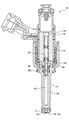
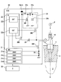
- FIG. 1 is a schematic diagram illustrating a fuel injection control device according to a first embodiment of the present disclosure and a fuel injection system including the device.
- Sectional drawing which shows the whole structure of a fuel injection valve in 1st Embodiment.
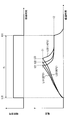
- the injection control is performed in the first embodiment, the change in the applied voltage to the coil, the coil current, the electromagnetic attractive force, and the lift amount with the passage of time is shown, and the relationship between the energization time and the injection amount is shown.
- Figure. The figure which shows that the characteristic line showing the relationship between electricity supply time and injection quantity becomes a different shape according to coil temperature.
- the change in voltage applied to the coil, coil current, electromagnetic attraction force and lift amount with time is shown, and the relationship between energization time and injection amount is shown.
- FIG. The figure which shows the peak appearance range in 5th Embodiment of this indication.
- a fuel injection valve 10 shown in FIG. 1 is mounted on an internal combustion engine (gasoline engine) and directly injects fuel into the combustion chamber 2 of the internal combustion engine. Specifically, a mounting hole 4 for inserting the fuel injection valve 10 is formed in the cylinder head 3 forming the combustion chamber 2. The fuel supplied to the fuel injection valve 10 is pumped by the fuel pump P, and the fuel pump P is driven by the rotational driving force of the internal combustion engine.
- the fuel injection valve 10 includes a body 11, a valve body 12, a coil 13, a fixed core 14, a movable core 15, an injection hole body 17, and the like.
- the body 11 is made of a metallic magnetic material so that the fuel passage 11a is formed inside.
- the body 11 houses the valve body 12, the fixed core 14, and the movable core 15, and holds the injection hole body 17.
- the injection hole body 17 is formed with a seating surface 17b on which the valve body 12 is seated and seated, and an injection hole 17a for injecting fuel.
- the valve body 12 is closed so that the seat surface 12a formed on the valve body 12 is seated on the seating surface 17b, the fuel injection from the injection hole 17a is stopped.
- the valve element 12 is opened (lifted up) so as to separate the seat surface 12a from the seating surface 17b, fuel is injected from the injection hole 17a.
- the fixed core 14 is formed in a cylindrical shape with a metal magnetic material, and forms a fuel passage 14a inside the cylinder.
- the movable core 15 is formed in a disk shape from a metal magnetic material, and is disposed opposite the fixed core 14 so as to have a predetermined gap with the fixed core 14 when the coil 13 is not energized.
- the fixed core 14 and the movable core 15 form a magnetic circuit serving as a path for magnetic flux generated by energization of the coil 13.
- a through-hole 15a is formed in the movable core 15, and the valve body 12 is slidably attached to the movable core 15 by being inserted and disposed in the through-hole 15a. ing.
- a locking portion 12 d is formed at the end of the valve body 12 on the side opposite to the injection hole.
- the main spring SP1 is disposed on the side opposite to the injection hole of the valve body 12, and the sub spring SP2 is disposed on the injection hole side of the movable core 15. These springs SP1 and SP2 are coiled and elastically deformed in the direction of the central axis C.
- the elastic force (main elastic force Fs1) of the main spring SP1 is applied to the valve body 12 on the valve closing side.
- the elastic force (sub elastic force Fs2) of the sub spring SP2 is applied to the movable core 15 on the valve opening side.
- the valve body 12 is sandwiched between the main spring SP1 and the seating surface 17b, and the movable core 15 is sandwiched between the sub spring SP2 and the locking portion 12d. Then, the elastic force Fs2 of the subspring SP2 is transmitted to the locking portion 12d via the movable core 15, and is given to the valve body 12 in the valve opening direction. Therefore, it can be said that the elastic force Fs obtained by subtracting the sub elastic force Fs2 from the main elastic force Fs1 is applied to the valve body 12 in the valve closing direction.
- the electronic control unit (ECU) 20 includes a microcomputer 21, an integrated IC 22, a booster circuit 23, switching elements SW2, SW3, SW4, and the like.
- the ECU 20 provides a fuel injection control device that controls the fuel injection amount by controlling the operation of the fuel injection valve 10.
- the ECU 20 and the fuel injection valve 10 provide a fuel injection system that injects an optimal amount of fuel.
- the microcomputer 21 includes a central processing unit, a nonvolatile memory, a volatile memory, and the like, and calculates a target fuel injection amount and a target injection start timing based on the load and engine speed of the internal combustion engine.
- the injection characteristic (Ti-q characteristic line) indicating the relationship between the energization time Ti and the injection amount q is obtained by testing in advance, and the energization time Ti to the coil 13 is controlled according to the injection characteristic.
- the injection amount q is controlled.
- Reference numeral t10 in FIG. 3A to be described later indicates the start time of the energization time
- reference numeral t60 indicates the end time of the energization time.
- the integrated IC 22 includes an injection drive circuit 22a that controls the operation of the switching elements SW2, SW3, and SW4, and a charging circuit 22b that controls the operation of the booster circuit 23. These circuits 22 a and 22 b operate based on the injection command signal output from the microcomputer 21.
- the injection command signal is a signal for instructing the energization state of the coil 13 of the fuel injection valve 10, and is executed by the microcomputer 21 based on the target injection amount and target injection start timing described above and the coil current detection value I described later. Is set.
- the injection command signal includes an injection signal, a boost signal, and a battery signal, which will be described later.
- the booster circuit 23 includes a coil 23a, a capacitor 23b, a diode 23c, and a switching element SW1.
- the charging circuit 22b controls the switching element SW1 so that the switching element SW1 is repeatedly turned on and off, the battery voltage applied from the battery terminal Batt is boosted (boosted) by the coil 23a and stored in the capacitor 23b. .
- the voltage of the electric power boosted and stored in this way corresponds to the “boost voltage”.
- the injection drive circuit 22a turns on both the switching elements SW2 and SW4, a boost voltage is applied to the coil 13 of the fuel injection valve 10.
- the switching element SW2 is turned off and the switching element SW3 is turned on, the battery voltage is applied to the coil 13 of the fuel injection valve 10.
- the switching elements SW2, SW3, SW4 are turned off.
- the diode 24 is for preventing the boost voltage from being applied to the switching element SW3 when the switching element SW2 is turned on.
- the shunt resistor 25 is for detecting a current flowing through the switching element SW4, that is, a current flowing through the coil 13 (coil current).
- the microcomputer 21 is based on the voltage drop amount generated in the shunt resistor 25 as described above.
- the coil current detection value I is detected.
- the electromagnetic attractive force when saturated and reaches the maximum value is referred to as a static attractive force Fb.
- the electromagnetic attraction force necessary for the valve body 12 to start the valve opening operation is referred to as a necessary valve opening force Fa.
- the higher the pressure of the fuel supplied to the fuel injection valve 10 the greater the electromagnetic attraction force (required valve opening force) required for the valve body 12 to start the valve opening operation.
- the required valve opening force increases according to various situations such as when the viscosity of the fuel is high. Therefore, the maximum value of the required valve opening force when the situation where the required valve opening force is maximized is defined as the required valve opening force Fa.
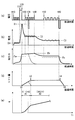
- FIG. 3 (a) shows a voltage waveform applied to the coil 13 when the valve element 12 is opened once and fuel injection is performed.
- the solid line shows the waveform when the coil 13 is at room temperature
- the dotted line in the figure shows the waveform when the coil 13 is at high temperature.
- the boost voltage is applied to start energization at the voltage application start time (see t10) commanded by the injection command signal. Then, the coil current increases with the start of energization (see FIG. 3B). The energization is turned off when the coil current detection value I reaches the first target value I1 (see t20). In short, control is performed so that the coil current is increased to the first target value I1 by applying the boost voltage by the first energization.
- the microcomputer 21 during such control corresponds to the “rise controller 21a”. Further, the first target value I1 corresponds to a “predetermined threshold value”.
- energization by the battery voltage is controlled so that the coil current is maintained at the second target value I2 set to a value lower than the first target value I1.
- the average value of the fluctuating coil current is changed to the second target value I2 by repeatedly turning on and off the battery voltage so that the deviation between the coil current detection value I and the second target value I2 is within a predetermined range.
- the duty is controlled so that The microcomputer 21 during such control corresponds to the “constant current control unit 21b”.
- the second target value I2 is set to a value such that the static suction force Fb is equal to or greater than the required valve opening force Fa.
- the energization by the battery voltage is controlled so that the coil current is maintained at the third target value I3 set to a value lower than the second target value I2.
- the average value of the fluctuating coil current is changed to the third target value I3 by repeatedly turning on and off the battery voltage so that the deviation between the coil current detection value I and the third target value I3 is within a predetermined range.
- the duty is controlled so that The microcomputer 21 during such control corresponds to the “hold control unit 21c”.
- the electromagnetic attractive force continues to increase during a period from the start of energization, that is, the increase control start time (t10) to the constant current control end time (t40). Note that the rate of increase of the electromagnetic attractive force is slower in the constant current control period than in the increase control period.
- the suction force is held at a predetermined value.
- the third target value I3 is set so that the predetermined value is higher than the valve opening holding force Fc required to hold the valve open state.
- the valve opening holding force Fc is smaller than the required valve opening force Fa.
- the injection signal included in the injection command signal is a pulse signal for instructing the energization time Ti, and the pulse-on time is set at a time (t10) earlier than the target injection start time by a predetermined injection delay time.
- the pulse-off timing is set at the energization end timing (t60) when the energization time Ti has elapsed since the pulse was turned on.
- the switching element SW4 operates according to this injection signal.
- the boost signal included in the injection command signal is a pulse signal that commands on / off of energization by the boost voltage, and turns on at the same time as the pulse of the injection signal is turned on. Thereafter, the boost signal is turned on until the coil current detection value I reaches the first target value I1. Thereby, the boost voltage is applied to the coil 13 in the increase control period.
- the battery signal included in the injection command signal is turned on at the constant current control start time t30. Thereafter, the battery signal is repeatedly turned on and off so as to perform feedback control so that the coil current detection value I is held at the second target value I2 until the elapsed time from the start of energization reaches a predetermined time. Thereafter, the battery signal is repeatedly turned on and off so as to perform feedback control so that the coil current detection value I is held at the third target value I3 during the period until the pulse of the injection signal is turned off.
- the switching element SW3 operates according to this battery signal.
- the valve body 12 starts the valve opening operation when the injection delay time has elapsed from the start of energization (t10), that is, at the time t1 when the suction force reaches the required valve opening force Fa. .
- the symbol t3 in the figure indicates the timing at which the valve body 12 reaches the maximum valve opening position (full lift position), and the symbol t4 in the figure indicates the timing at which the valve body 12 starts to close.
- the valve body 12 starts the valve closing operation at the time when the delay time has elapsed from the energization end timing (t60), that is, at the time t4 when the suction force is reduced to the valve opening holding force Fc.
- a voltage obtained by reversing positive and negative is applied to the coil 13 simultaneously with the injection end command timing.
- the coil current flows in the direction opposite to the coil current during the energization time Ti (t10 to t60), and the valve closing speed of the valve body 12 is increased. That is, the valve closing delay time from the energization end timing t60 to the time t5 when the valve body 12 is seated and closes can be shortened.
- Such reverse voltage application after the energization end timing t60 is not included in the energization time Ti calculated by the energization time calculation unit S40 described later, and is not included in the energization time Ti of the Ti-q characteristic line.
- FIG. 3 (e) represents a characteristic line representing the relationship between the energization time Ti and the injection amount q, and the elapsed time (a) to (d) and the energization time Ti are shown together.
- the time point t31 (see FIG. 3A) during which the coil current is being held at the second target value I2 is set as the end time of the energization time to turn off the pulse of the injection signal.
- the suction force starts decreasing and the valve body 12 starts the valve closing operation.
- the injection amount in this case is the injection amount q31 corresponding to t31 in the characteristic line shown in FIG.
- the pressure (fuel pressure Pc) of the fuel supplied to the fuel injection valve 10 is detected by the fuel pressure sensor 30 shown in FIG.
- the ECU 20 determines whether or not to perform the above-described constant current control according to the fuel pressure Pc detected by the fuel pressure sensor 30. For example, when the fuel pressure Pc is equal to or greater than a predetermined threshold value Pth, constant current control is permitted. On the other hand, when the fuel pressure Pc is less than the predetermined threshold value Pth, the electromagnetic attractive force required to start the valve opening operation is small, so the constant current control is not performed and the hold control is performed after the ascent control. To do.
- the slope of the Ti-q characteristic line becomes small.
- the region in the period t1 to t3 is called “partial region A1”, and the region after t3 is called “full lift region A2”. That is, in the partial region A1, the valve body 12 starts the valve closing operation before reaching the maximum valve opening position, and a small amount of fuel (see symbol q31) is injected.
- FIG. 4 is a test result showing the shape of the Ti-q characteristic line that varies with temperature.
- the characteristic line L1 in the figure shows the result of testing at room temperature.
- the characteristic line L2 shows the result of testing by passing a current through the coil 13 through a resistance corresponding to 80 ° C.
- a characteristic line L3 shows a test result when a current is passed through the coil 13 through a resistance corresponding to 140 ° C.
- the inventors obtained the following knowledge. That is, in the partial region A1, in the energization time region (decrease region) shorter than the peak appearance range W1 described later, the injection amount with respect to the energization time decreases as the coil temperature increases. On the other hand, in the partial region A1, in the energization time region (increase region) longer than the peak appearance range W1, the injection amount with respect to the energization time increases as the coil temperature increases.
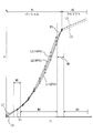
- FIG. 5 shows the results of testing and measuring the coil current change (current waveform) caused by the control of the ascent control unit 21a and the constant current control unit 21b.
- the energization is terminated at time t31 when the coil current is held at the second target value I2 by the constant current control unit 21b, and the energization time Ti corresponding to the injection amount in the partial area A1 is set. .
- the current waveform L10 in the figure shows the result of testing at room temperature.
- a current waveform L20 shows a test result when a current is passed through the coil 13 through a resistor corresponding to 80 ° C.
- a current waveform L30 shows a test result when a current is passed through the coil 13 through a resistance corresponding to 140 ° C.
- Symbols t21, t22, and t23 in the figure indicate times when the current reaches a peak value when the increase control unit 21a is terminated and the application of the boost voltage is stopped.
- the higher the coil temperature the longer the time until the current reaches the first target value I1, and the peak value appears later. This is because the higher the coil temperature, the higher the resistance of the coil 13. Therefore, if energization is terminated before the appearance times t21, t22, and t23 of peak values, the injection amount for the energization time Ti decreases as the coil temperature increases. That is, in the energization time Ti on the side shorter than the peak appearance range W1 in FIG. 4, the low-temperature characteristic line L1 is positioned above the high-temperature characteristic line L3 among the three characteristic lines L1, L2, and L3. .
- the characteristic line L3 at high temperature of the three characteristic lines L1, L2, and L3 is higher than the characteristic line L1 at low temperature in the energization time Ti longer than the peak appearance range W1 in FIG. Is also located on the upper side. That is, when the energization time Ti is set shorter than the peak appearance range W1, the injection amount with respect to the energization time decreases as the coil temperature increases. On the other hand, when the energization time Ti is set longer than the peak appearance range W1, the injection amount with respect to the energization time increases as the coil temperature increases. That is, the increase and decrease depending on the temperature of the injection amount with respect to the energization time Ti are switched at the peak appearance range W1.
- the energization time Ti is set in the region indicated by reference numeral B1 in FIG. 4 so that the end times t31 and t60 of the energization time Ti are later than the peak appearance range W1.
- the procedure for calculating the energization time Ti will be described with reference to FIG.
- FIG. 6 is a flowchart showing a procedure of processing that the microcomputer 21 repeatedly executes at predetermined time intervals in accordance with a program.
- step S10 the rotational speed NE and load per unit time of the internal combustion engine at the present time are acquired.
- the load include a depression amount of an accelerator pedal operated by a driver, an intake air flow rate or an intake negative pressure.
- a target value (total target injection amount) of the total amount of fuel injected into one cylinder during one combustion cycle is calculated based on the acquired rotational speed NE and load.
- the calculated total number of injections in one combustion cycle, the number of divisions of the total target injection amount, and the target injection amount of fuel injected by one opening of the fuel injection valve 10 are calculated. Set based on the target injection amount. The sum of the target injection amounts relating to the respective injections divided in one combustion cycle matches the total target injection amount.
- step S40 energization time Ti is calculated for each set target injection amount. Specifically, first, in step S41, a base value of the energization time Ti corresponding to the target injection amount is set. Specifically, in the case where the operating temperature range is from ⁇ 30 ° C. to 200 ° C., a map related to the Ti-q characteristic line at the center temperature is stored in the microcomputer 21 in advance. And based on the said map, the value of the electricity supply time Ti with respect to the injection quantity is set as a base value.
- the temperature of the coil 13 is estimated.
- the time required for the coil current to increase to the first target value I1 by the increase controller 21a has a high correlation with the coil temperature. Therefore, the above time is detected, and the coil temperature is estimated based on the time.
- a correction value for the base value of the energization time Ti is calculated based on the estimated coil temperature.
- the injection amount increases as the temperature rises as shown in FIG. 4. Therefore, the correction value is a value in which the base value is corrected to be shorter as the temperature is higher. Is set.
- a value obtained by adding the correction value calculated in step S43 to the base value of the energization time Ti set in step S41 is calculated as the energization time Ti.
- the correction value is calculated to correct the energization time Ti.
- the change in the injection amount that occurs according to the temperature is extremely small. Therefore, when the base value is the full lift region A2, the correction value is not calculated and corrected.
- step S30 the target injection amount and the number of divisions are set so that the end time t31 of the energization time Ti set in step S40 is later than the peak appearance range W1. That is, by adjusting the number of divisions, the target injection amount is set so that the end timing t31 is later than the peak appearance range W1.
- the resistance value, boost voltage, and first target value I1 of the coil 13 are set so that the minute injection amount in the partial region A1 can be included in the target injection amount setting range. That is, as the resistance value of the coil 13 is larger, the boost voltage is smaller, or the first target value I1 is smaller, the peak appearance range W1 is positioned on the longer energization time Ti side. Then, there is a case where the partial area A1 does not exist on the side later than the peak appearance range W1. The resistance value of the coil 13, the boost voltage, and the first target value I1 are set so as not to fall into such a situation.
- the microcomputer 21 executing the process of step S40 corresponds to the “energization time calculating unit”, and the microcomputer 21 executing the process of step S30 is the “target injection amount setting unit”. Equivalent to.
- the target injection amount is set in step S30 of FIG. 6 so that the end time t31 of the energization time Ti falls outside the peak appearance range W1. For this reason, when the temperature of the base value of the energization time Ti corresponding to the target injection amount is temperature-corrected, it is uniquely specified whether the correction should be increased or decreased as the temperature increases. Therefore, it is not necessary to switch between the case of increasing correction and the case of decreasing correction as the temperature is higher for the same target injection amount. Therefore, since the concern of reversing the increase / decrease in the correction can be solved, the fuel injection amount can be controlled with high accuracy.
- the target injection amount is set so that the end time t31 of the energization time Ti is a time later than the peak appearance range W1.
- the peak appearance range W1 needs to be set sufficiently late. Then, it is necessary to increase the resistance value of the coil 13, lower the boost voltage, and lower the first target value I1. Then, the valve opening response delay time from when the energization is started until the valve body 12 starts the valve opening operation becomes long, and the response of the operation of the fuel injection valve 10 is deteriorated.
- the end time t31 of the energization time Ti is set to a time later than the peak appearance range W1, and thus the above-described problem of deterioration in responsiveness can be avoided.
- the following conditions are satisfied so that the minute injection amount in the partial region A1 can be included in the target injection amount setting range while satisfying the condition that the end timing t31 deviates from the peak appearance range W1.
- a value is set. That is, the resistance value of the coil 13 is set sufficiently small, the boost voltage is set sufficiently high, and the first target value I1 (that is, the current peak value) is set sufficiently high. According to this, in the partial area A1, the amount of variation due to the temperature of the characteristic lines L1, L2, and L3 can be reduced. Therefore, the accuracy of temperature correction in the partial area A1 can be improved.
- the peak appearance range W1 can also be said to be a change point appearance range that is a range in which the change point Pf of the electromagnetic attractive force can appear in the operating temperature range. Therefore, setting the target injection amount so that the end time t31 of the energization time Ti is outside the peak appearance range W1 means that the target injection is such that the end time t31 is outside the change point appearance range. In other words, the amount can be set.
- the target injection amount is set in step S30 of FIG. 6 so that the end time t31 of the energization time Ti is outside the peak appearance range.
- the target injection amount is set so that the end time t31 of the energization time Ti falls outside the cross point appearance ranges W2 and W3 described below.
- cross points P1 and P2 points where characteristic lines L1, L2, and L3 intersect with each other are referred to as cross points P1 and P2.
- the cross point between the characteristic line L1 and the characteristic line L2, the cross point between the characteristic line L1 and the characteristic line L3, and the cross point between the characteristic line L2 and the characteristic line L3 are the same positions (positions P1 and P2). Is shown in FIG. However, strictly speaking, these cross points appear at different positions.
- the ranges where the cross points P1, P2 can appear according to the operating temperature range of the coil 13 are the cross point appearance ranges W2, W3.
- a specific example of the use temperature range of the coil 13 is a use range of ⁇ 30 ° C. to 200 ° C.
- the range from which the end time t31 is removed is one place of the peak appearance range W1
- the cross point appearance ranges W2 and W3 exist at two places, and the end time There are two ranges for removing t31.
- the energization time Ti is set in the areas indicated by reference numerals B2 and B3 in FIG.
- One cross point appearance range W2 partially overlaps with the peak appearance range W1.
- One cross point appearance range W3 includes a boundary between the partial area A1 and the full lift area A2.
- the target injection amount is set so that the end time t31 of the energization time Ti is a time deviating from the cross point appearance ranges W2 and W3. For this reason, when the temperature of the base value of the energization time Ti corresponding to the target injection amount is temperature-corrected, it is uniquely specified whether the correction should be increased or decreased as the temperature increases. Therefore, it is not necessary to switch between the case of increasing correction and the case of decreasing correction as the temperature is higher for the same target injection amount. Therefore, since the concern of reversing the increase / decrease in the correction can be solved, the fuel injection amount can be controlled with high accuracy.
- the minute injection amount in the partial region A1 can be included in the target injection amount setting range while satisfying the condition that the end timing t31 is out of the cross point appearance ranges W2 and W3.
- the following values are set. That is, the resistance value of the coil 13 is set sufficiently small, the boost voltage is set sufficiently high, and the first target value I1 (that is, the current peak value) is set sufficiently high. According to this, in the partial area A1, the amount of variation due to the temperature of the characteristic lines L1, L2, and L3 can be reduced. Therefore, the accuracy of temperature correction in the partial area A1 can be improved.
- the microcomputer 21 provides a precharge control unit 21d described below. That is, the microcomputer 21 controls the integrated IC 22 so as to perform a precharge in which the battery voltage is applied to the coil 13 prior to the application of the boost voltage by the increase control unit 21a. The microcomputer 21 under such control corresponds to the “precharge control unit 21d”.
- the integrated IC 22 controlled by the microcomputer 21 to perform the precharge turns on the switching element SW4 and turns on and off the switching element SW4 so that the coil current is maintained at the fourth target value I4 (FIG. 9).
- the fourth target value I4 is set to a value smaller than the third target value I3 (see FIG. 9B).
- the precharge control for applying the battery voltage to the coil 13 is started at the time t0 set a predetermined time before the time t10 when the rising control starts. Thereby, prior to the start of the raising control, the suction force starts to rise (see FIG. 9C).
- the boost voltage application period required to increase the coil current to the first target value I1 in the increase control can be shortened. Therefore, the amount of heat generated by the booster circuit 23 can be reduced, and the risk of thermal damage to the ECU 20 can be reduced.
- the target injection amount is set so that the end time t31 of the energization time Ti falls outside the peak appearance range W1 as in the first embodiment.
- the precharge control is performed, the time required to increase the coil current to the first target value I1 by the increase control is shortened. Therefore, the appearance time of the peak value of the coil current is advanced, and the peak appearance range W1 is shifted to the early side. Therefore, the setting area B1 shown in FIG. 4 can be expanded early, and the minimum value of the energization time Ti that can be set can be reduced.
- the fear of reversing the increase / decrease in the correction is solved, the fuel injection amount can be controlled with high accuracy, and the minimum target injection amount that can be set is reduced. become able to.
- the target injection amount is set so that the end time t31 of the energization time Ti is out of the peak appearance range W1 after the precharge control unit 21d is provided.
- the precharge control unit 21d is provided in the same manner as in the third embodiment, and the end timing t31 of the energization time Ti is set to the cross point appearance range W2 in the same manner as in the second embodiment.
- the target injection amount is set so as to be out of W3.
- the present embodiment can provide the same effects as those of the third embodiment. That is, it is possible to control the fuel injection amount with high accuracy by eliminating the concern that the increase / decrease in the correction is reversed, and to reduce the minimum target injection amount that can be set.
- the setting of the resistance value of the coil 13, the boost voltage, and the first target value I1 is the same. Therefore, the characteristic lines L1, L2, and L3 shown in FIG. 4 are the same as the characteristic lines L1, L2, and L3 shown in FIG.
- the setting of the resistance value of the coil 13, the boost voltage, and the first target value I1 is changed.
- the energization time Ti is set in the region indicated by reference sign B1 in FIG. 4 so that the end time t31 of the energization time Ti is a time later than the peak appearance range W1. .
- the energization time Ti is set in both the region earlier than the peak appearance range W4 (see symbol B4) and the later region (see symbol B5).
- the slower area B5 is set so as not to include the partial area A1. Therefore, in the partial area A1, the end time t31 is set in the area B4, and in the full lift area A2, the end time t60 is set in the area B5.
- the resistance value, boost voltage, and first target value I1 of the coil 13 are set so that the peak appearance ranges W1 and W4 are located in the partial region A1.
- the resistance value, the boost voltage, and the first target value I1 of the coil 13 may be set so that the peak appearance ranges W1 and W4 are located in the full lift region A2.
- a feedback control unit that includes an injection amount estimation unit that estimates the amount of actual injection, and that learns the deviation between the estimated actual injection amount and the target injection amount and feeds back to the next energization time Ti setting May be provided.
- the target injection amount is set such that the end times t31 and t60 of the energization time Ti deviate from the peak appearance ranges W1 and W4 or the cross point appearance ranges W2 and W3. May be set.
- the injection amount estimation unit the actual injection amount is detected based on the detection result and the fuel pressure Pc detected by the fuel pressure sensor 30 when the valve body 12 is actually opened and closed. Is estimated.
- the time point (t20) when the coil current reaches the first target value I1 is the peak appearance time.
- switching from the boost voltage to the battery voltage may be continued, and the increased coil current may be held for the predetermined time with the first target value I1. In this case, the time when the boost voltage is switched to the battery voltage corresponds to the peak appearance time.
- the fuel injection valve 10 is attached to the cylinder head 3 as shown in FIG. 1, but the fuel injection valve attached to the cylinder block may be applied.
- the fuel injection valve 10 mounted on the ignition type internal combustion engine gasoline engine
- the fuel injection valve mounted on the compression ignition type internal combustion engine diesel engine
- the fuel injection valve which injects a fuel directly to the combustion chamber 2 is made into control object, it is good also considering the fuel injection valve which injects fuel into an intake pipe as control object.
Priority Applications (3)
| Application Number | Priority Date | Filing Date | Title |
|---|---|---|---|
| CN201480063608.7A CN105765202B (zh) | 2013-11-21 | 2014-11-10 | 燃料喷射控制装置以及燃料喷射系统 |
| US15/037,447 US9970376B2 (en) | 2013-11-21 | 2014-11-10 | Fuel injection controller and fuel injection system |
| DE112014005317.1T DE112014005317B4 (de) | 2013-11-21 | 2014-11-10 | Kraftstoffeinspritzsteuerungsvorrichtung und Kraftstoffeinspritzsystem |
Applications Claiming Priority (2)
| Application Number | Priority Date | Filing Date | Title |
|---|---|---|---|
| JP2013241238A JP6318575B2 (ja) | 2013-11-21 | 2013-11-21 | 燃料噴射制御装置および燃料噴射システム |
| JP2013-241238 | 2013-11-21 |
Publications (1)
| Publication Number | Publication Date |
|---|---|
| WO2015075887A1 true WO2015075887A1 (ja) | 2015-05-28 |
Family
ID=53179180
Family Applications (1)
| Application Number | Title | Priority Date | Filing Date |
|---|---|---|---|
| PCT/JP2014/005621 WO2015075887A1 (ja) | 2013-11-21 | 2014-11-10 | 燃料噴射制御装置および燃料噴射システム |
Country Status (5)
| Country | Link |
|---|---|
| US (1) | US9970376B2 (de) |
| JP (1) | JP6318575B2 (de) |
| CN (1) | CN105765202B (de) |
| DE (1) | DE112014005317B4 (de) |
| WO (1) | WO2015075887A1 (de) |
Cited By (2)
| Publication number | Priority date | Publication date | Assignee | Title |
|---|---|---|---|---|
| CN109328264A (zh) * | 2016-05-06 | 2019-02-12 | 丰田自动车株式会社 | 燃料喷射控制装置 |
| CN109328262A (zh) * | 2016-05-06 | 2019-02-12 | 丰田自动车株式会社 | 燃料喷射控制装置 |
Families Citing this family (17)
| Publication number | Priority date | Publication date | Assignee | Title |
|---|---|---|---|---|
| JP6318575B2 (ja) | 2013-11-21 | 2018-05-09 | 株式会社デンソー | 燃料噴射制御装置および燃料噴射システム |
| JP6233080B2 (ja) * | 2014-02-10 | 2017-11-22 | 株式会社デンソー | 燃料噴射制御装置 |
| JP6414022B2 (ja) * | 2015-11-05 | 2018-10-31 | 株式会社デンソー | 燃料噴射制御装置と燃料噴射システム |
| DE102016219881B3 (de) | 2016-10-12 | 2017-11-23 | Continental Automotive Gmbh | Betreiben eines Kraftstoffinjektors mit hydraulischem Anschlag |
| DE102016219888B3 (de) | 2016-10-12 | 2017-11-23 | Continental Automotive Gmbh | Betreiben eines Kraftstoffinjektors mit hydraulischem Anschlag |
| JP6610571B2 (ja) * | 2017-01-20 | 2019-11-27 | トヨタ自動車株式会社 | 内燃機関の燃料噴射制御装置 |
| DE102017205884A1 (de) * | 2017-04-06 | 2018-10-11 | Continental Automotive Gmbh | Verfahren zum Schalten eines Stromes in einem Elektromagneten eines schaltbaren Magnet-Ventils sowie elektronische Schaltung, Magnet-Ventil, Pumpe und Kraftfahrzeug |
| JP6720935B2 (ja) * | 2017-07-28 | 2020-07-08 | 株式会社Soken | 燃料噴射制御装置及び燃料噴射制御方法 |
| JP7068021B2 (ja) * | 2018-04-27 | 2022-05-16 | トヨタ自動車株式会社 | 内燃機関の制御装置 |
| US10900391B2 (en) * | 2018-06-13 | 2021-01-26 | Vitesco Technologies USA, LLC. | Engine control system and method for controlling activation of solenoid valves |
| US20200025122A1 (en) * | 2018-07-17 | 2020-01-23 | Continental Automotive Systems, Inc. | Engine control system and method for controlling activation of solenoid valves |
| FR3087493B1 (fr) * | 2018-10-22 | 2022-01-21 | Continental Automotive France | Procede de controle d'un convertisseur de tension continu-continu pour le pilotage d'un injecteur de carburant |
| BR102018077407A2 (pt) * | 2018-12-28 | 2020-07-07 | Robert Bosch Limitada | método para injeção otimizada de combustível em sistemas de bombas de combustível diesel |
| GB2590969A (en) * | 2020-01-10 | 2021-07-14 | Ford Global Tech Llc | Method and apparatus for fuel injection control |
| JP7361644B2 (ja) * | 2020-03-24 | 2023-10-16 | 日立Astemo株式会社 | 電磁弁駆動装置 |
| KR102514687B1 (ko) * | 2021-05-11 | 2023-03-27 | 주식회사 현대케피코 | 지디아이 엔진 인젝터의 부스트 전압 제어 장치 및 방법 |
| EP4098859A1 (de) * | 2021-05-31 | 2022-12-07 | Marelli Europe S.p.A. | Verfahren zur schätzung der temperatur eines elektromagnetischen aktuators |
Citations (4)
| Publication number | Priority date | Publication date | Assignee | Title |
|---|---|---|---|---|
| JP2009074373A (ja) * | 2007-09-19 | 2009-04-09 | Hitachi Ltd | 内燃機関の燃料噴射制御装置 |
| JP2011052631A (ja) * | 2009-09-03 | 2011-03-17 | Denso Corp | 燃料噴射制御装置 |
| JP2013124584A (ja) * | 2011-12-14 | 2013-06-24 | Toyota Motor Corp | 内燃機関の制御装置 |
| JP2013137028A (ja) * | 2013-03-01 | 2013-07-11 | Hitachi Automotive Systems Ltd | 内燃機関の燃料噴射制御装置及び方法 |
Family Cites Families (21)
| Publication number | Priority date | Publication date | Assignee | Title |
|---|---|---|---|---|
| JP2963407B2 (ja) * | 1997-02-14 | 1999-10-18 | 本田技研工業株式会社 | 燃料噴射弁制御装置 |
| US6148800A (en) | 1999-04-01 | 2000-11-21 | Daimlerchrysler Corporation | Injection temperature fuel feedback |
| JP2002021679A (ja) | 2000-06-30 | 2002-01-23 | Hitachi Ltd | 燃料噴射装置及び内燃機関 |
| DE10148346A1 (de) | 2000-10-18 | 2002-05-02 | Bosch Gmbh Robert | Verfahren, Vorrichtung und Computerprogramm zum Betreiben einer Brennkraftmaschine, sowie Brennkraftmaschine |
| JP2004511715A (ja) * | 2000-10-18 | 2004-04-15 | ロベルト・ボッシュ・ゲゼルシャフト・ミト・ベシュレンクテル・ハフツング | 内燃機関の運転方法および装置 |
| JP4158501B2 (ja) * | 2002-03-06 | 2008-10-01 | 株式会社デンソー | 蓄圧式燃料噴射装置 |
| JP2007285139A (ja) * | 2006-04-13 | 2007-11-01 | Denso Corp | ディーゼル機関の制御装置 |
| JP2010255444A (ja) * | 2009-04-21 | 2010-11-11 | Hitachi Automotive Systems Ltd | 内燃機関の燃料噴射制御装置及び方法 |
| JP4859951B2 (ja) * | 2009-05-14 | 2012-01-25 | 三菱電機株式会社 | 車載エンジン制御装置 |
| JP5058239B2 (ja) | 2009-10-30 | 2012-10-24 | 日立オートモティブシステムズ株式会社 | 内燃機関の燃料噴射制御装置 |
| JP2012102658A (ja) * | 2010-11-09 | 2012-05-31 | Honda Motor Co Ltd | 内燃機関の燃料噴射制御装置 |
| JP5492806B2 (ja) * | 2011-02-25 | 2014-05-14 | 日立オートモティブシステムズ株式会社 | 電磁式燃料噴射弁の駆動装置 |
| JP5358621B2 (ja) * | 2011-06-20 | 2013-12-04 | 日立オートモティブシステムズ株式会社 | 燃料噴射装置 |
| JP5754357B2 (ja) * | 2011-11-18 | 2015-07-29 | 株式会社デンソー | 内燃機関の燃料噴射制御装置 |
| US8730723B2 (en) * | 2012-03-12 | 2014-05-20 | Flashsilicon Incorporation | Structures and methods of high efficient bit conversion for multi-level cell non-volatile memories |
| JP2013241238A (ja) | 2012-05-18 | 2013-12-05 | Mitsubishi Electric Corp | マンコンベアの監視装置、及びそのマンコンベアの監視装置を備えたマンコンベア |
| JP5982484B2 (ja) * | 2012-06-21 | 2016-08-31 | 日立オートモティブシステムズ株式会社 | 内燃機関の制御装置 |
| JP5874607B2 (ja) * | 2012-11-05 | 2016-03-02 | 株式会社デンソー | 燃料噴射制御装置および燃料噴射システム |
| JP5875559B2 (ja) * | 2013-08-30 | 2016-03-02 | 日立オートモティブシステムズ株式会社 | 燃料噴射装置の駆動回路 |
| JP6318575B2 (ja) | 2013-11-21 | 2018-05-09 | 株式会社デンソー | 燃料噴射制御装置および燃料噴射システム |
| JP6233080B2 (ja) * | 2014-02-10 | 2017-11-22 | 株式会社デンソー | 燃料噴射制御装置 |
-
2013
- 2013-11-21 JP JP2013241238A patent/JP6318575B2/ja active Active
-
2014
- 2014-11-10 WO PCT/JP2014/005621 patent/WO2015075887A1/ja active Application Filing
- 2014-11-10 CN CN201480063608.7A patent/CN105765202B/zh active Active
- 2014-11-10 DE DE112014005317.1T patent/DE112014005317B4/de active Active
- 2014-11-10 US US15/037,447 patent/US9970376B2/en active Active
Patent Citations (4)
| Publication number | Priority date | Publication date | Assignee | Title |
|---|---|---|---|---|
| JP2009074373A (ja) * | 2007-09-19 | 2009-04-09 | Hitachi Ltd | 内燃機関の燃料噴射制御装置 |
| JP2011052631A (ja) * | 2009-09-03 | 2011-03-17 | Denso Corp | 燃料噴射制御装置 |
| JP2013124584A (ja) * | 2011-12-14 | 2013-06-24 | Toyota Motor Corp | 内燃機関の制御装置 |
| JP2013137028A (ja) * | 2013-03-01 | 2013-07-11 | Hitachi Automotive Systems Ltd | 内燃機関の燃料噴射制御装置及び方法 |
Cited By (4)
| Publication number | Priority date | Publication date | Assignee | Title |
|---|---|---|---|---|
| CN109328264A (zh) * | 2016-05-06 | 2019-02-12 | 丰田自动车株式会社 | 燃料喷射控制装置 |
| CN109328262A (zh) * | 2016-05-06 | 2019-02-12 | 丰田自动车株式会社 | 燃料喷射控制装置 |
| EP3453862A4 (de) * | 2016-05-06 | 2019-06-05 | Denso Corporation | Kraftstoffeinspritzungsteuerungsvorrichtung |
| CN109328262B (zh) * | 2016-05-06 | 2021-08-06 | 丰田自动车株式会社 | 燃料喷射控制装置 |
Also Published As
| Publication number | Publication date |
|---|---|
| DE112014005317T5 (de) | 2016-08-04 |
| CN105765202B (zh) | 2018-10-26 |
| JP6318575B2 (ja) | 2018-05-09 |
| CN105765202A (zh) | 2016-07-13 |
| US9970376B2 (en) | 2018-05-15 |
| DE112014005317B4 (de) | 2023-07-13 |
| JP2015101977A (ja) | 2015-06-04 |
| US20160298565A1 (en) | 2016-10-13 |
Similar Documents
| Publication | Publication Date | Title |
|---|---|---|
| JP6318575B2 (ja) | 燃料噴射制御装置および燃料噴射システム | |
| JP6233080B2 (ja) | 燃料噴射制御装置 | |
| US10598114B2 (en) | Fuel injection controller and fuel injection system | |
| JP6520814B2 (ja) | 燃料噴射制御装置 | |
| JP6520815B2 (ja) | 燃料噴射制御装置 | |
| US9228521B2 (en) | Fuel injection controller and fuel-injection-control system | |
| US10634084B2 (en) | Fuel injection controller and fuel injection system | |
| CN109328262B (zh) | 燃料喷射控制装置 | |
| JP6520816B2 (ja) | 燃料噴射制御装置 | |
| KR20150119872A (ko) | 자기 인젝터의 분사 과정을 제어하기 위한 방법 | |
| CN109072808B (zh) | 燃料喷射控制装置 | |
| WO2019225076A1 (ja) | 燃料噴射制御装置 | |
| JP2017089437A (ja) | 燃料噴射制御装置と燃料噴射システム | |
| US9194345B2 (en) | Fuel injection device | |
| US9249766B2 (en) | Fuel injector and fuel injection device using the same | |
| JP2008175119A (ja) | インジェクタ制御装置 |
Legal Events
| Date | Code | Title | Description |
|---|---|---|---|
| 121 | Ep: the epo has been informed by wipo that ep was designated in this application |
Ref document number: 14863928 Country of ref document: EP Kind code of ref document: A1 |
|
| WWE | Wipo information: entry into national phase |
Ref document number: 15037447 Country of ref document: US |
|
| WWE | Wipo information: entry into national phase |
Ref document number: 112014005317 Country of ref document: DE |
|
| 122 | Ep: pct application non-entry in european phase |
Ref document number: 14863928 Country of ref document: EP Kind code of ref document: A1 |