WO2015075887A1 - Fuel injection control device and fuel injection system - Google Patents
Fuel injection control device and fuel injection system Download PDFInfo
- Publication number
- WO2015075887A1 WO2015075887A1 PCT/JP2014/005621 JP2014005621W WO2015075887A1 WO 2015075887 A1 WO2015075887 A1 WO 2015075887A1 JP 2014005621 W JP2014005621 W JP 2014005621W WO 2015075887 A1 WO2015075887 A1 WO 2015075887A1
- Authority
- WO
- WIPO (PCT)
- Prior art keywords
- coil
- injection amount
- time
- fuel injection
- energization time
- Prior art date
Links
Images


Classifications
-
- F—MECHANICAL ENGINEERING; LIGHTING; HEATING; WEAPONS; BLASTING
- F02—COMBUSTION ENGINES; HOT-GAS OR COMBUSTION-PRODUCT ENGINE PLANTS
- F02D—CONTROLLING COMBUSTION ENGINES
- F02D41/00—Electrical control of supply of combustible mixture or its constituents
- F02D41/24—Electrical control of supply of combustible mixture or its constituents characterised by the use of digital means
- F02D41/2406—Electrical control of supply of combustible mixture or its constituents characterised by the use of digital means using essentially read only memories
- F02D41/2425—Particular ways of programming the data
- F02D41/2429—Methods of calibrating or learning
- F02D41/2451—Methods of calibrating or learning characterised by what is learned or calibrated
- F02D41/2464—Characteristics of actuators
- F02D41/2467—Characteristics of actuators for injectors
-
- F—MECHANICAL ENGINEERING; LIGHTING; HEATING; WEAPONS; BLASTING
- F02—COMBUSTION ENGINES; HOT-GAS OR COMBUSTION-PRODUCT ENGINE PLANTS
- F02D—CONTROLLING COMBUSTION ENGINES
- F02D41/00—Electrical control of supply of combustible mixture or its constituents
- F02D41/20—Output circuits, e.g. for controlling currents in command coils
-
- F—MECHANICAL ENGINEERING; LIGHTING; HEATING; WEAPONS; BLASTING
- F02—COMBUSTION ENGINES; HOT-GAS OR COMBUSTION-PRODUCT ENGINE PLANTS
- F02D—CONTROLLING COMBUSTION ENGINES
- F02D41/00—Electrical control of supply of combustible mixture or its constituents
- F02D41/30—Controlling fuel injection
- F02D41/38—Controlling fuel injection of the high pressure type
- F02D41/40—Controlling fuel injection of the high pressure type with means for controlling injection timing or duration
-
- F—MECHANICAL ENGINEERING; LIGHTING; HEATING; WEAPONS; BLASTING
- F02—COMBUSTION ENGINES; HOT-GAS OR COMBUSTION-PRODUCT ENGINE PLANTS
- F02M—SUPPLYING COMBUSTION ENGINES IN GENERAL WITH COMBUSTIBLE MIXTURES OR CONSTITUENTS THEREOF
- F02M51/00—Fuel-injection apparatus characterised by being operated electrically
- F02M51/06—Injectors peculiar thereto with means directly operating the valve needle
- F02M51/061—Injectors peculiar thereto with means directly operating the valve needle using electromagnetic operating means
-
- F—MECHANICAL ENGINEERING; LIGHTING; HEATING; WEAPONS; BLASTING
- F02—COMBUSTION ENGINES; HOT-GAS OR COMBUSTION-PRODUCT ENGINE PLANTS
- F02D—CONTROLLING COMBUSTION ENGINES
- F02D41/00—Electrical control of supply of combustible mixture or its constituents
- F02D41/20—Output circuits, e.g. for controlling currents in command coils
- F02D2041/2003—Output circuits, e.g. for controlling currents in command coils using means for creating a boost voltage, i.e. generation or use of a voltage higher than the battery voltage, e.g. to speed up injector opening
- F02D2041/2006—Output circuits, e.g. for controlling currents in command coils using means for creating a boost voltage, i.e. generation or use of a voltage higher than the battery voltage, e.g. to speed up injector opening by using a boost capacitor
-
- F—MECHANICAL ENGINEERING; LIGHTING; HEATING; WEAPONS; BLASTING
- F02—COMBUSTION ENGINES; HOT-GAS OR COMBUSTION-PRODUCT ENGINE PLANTS
- F02D—CONTROLLING COMBUSTION ENGINES
- F02D41/00—Electrical control of supply of combustible mixture or its constituents
- F02D41/20—Output circuits, e.g. for controlling currents in command coils
- F02D2041/202—Output circuits, e.g. for controlling currents in command coils characterised by the control of the circuit
- F02D2041/2058—Output circuits, e.g. for controlling currents in command coils characterised by the control of the circuit using information of the actual current value
-
- F—MECHANICAL ENGINEERING; LIGHTING; HEATING; WEAPONS; BLASTING
- F02—COMBUSTION ENGINES; HOT-GAS OR COMBUSTION-PRODUCT ENGINE PLANTS
- F02D—CONTROLLING COMBUSTION ENGINES
- F02D41/00—Electrical control of supply of combustible mixture or its constituents
- F02D41/20—Output circuits, e.g. for controlling currents in command coils
- F02D2041/202—Output circuits, e.g. for controlling currents in command coils characterised by the control of the circuit
- F02D2041/2065—Output circuits, e.g. for controlling currents in command coils characterised by the control of the circuit the control being related to the coil temperature
-
- F—MECHANICAL ENGINEERING; LIGHTING; HEATING; WEAPONS; BLASTING
- F02—COMBUSTION ENGINES; HOT-GAS OR COMBUSTION-PRODUCT ENGINE PLANTS
- F02M—SUPPLYING COMBUSTION ENGINES IN GENERAL WITH COMBUSTIBLE MIXTURES OR CONSTITUENTS THEREOF
- F02M51/00—Fuel-injection apparatus characterised by being operated electrically
- F02M51/06—Injectors peculiar thereto with means directly operating the valve needle
- F02M51/061—Injectors peculiar thereto with means directly operating the valve needle using electromagnetic operating means
- F02M51/0625—Injectors peculiar thereto with means directly operating the valve needle using electromagnetic operating means characterised by arrangement of mobile armatures
- F02M51/0664—Injectors peculiar thereto with means directly operating the valve needle using electromagnetic operating means characterised by arrangement of mobile armatures having a cylindrically or partly cylindrically shaped armature, e.g. entering the winding; having a plate-shaped or undulated armature entering the winding
- F02M51/0671—Injectors peculiar thereto with means directly operating the valve needle using electromagnetic operating means characterised by arrangement of mobile armatures having a cylindrically or partly cylindrically shaped armature, e.g. entering the winding; having a plate-shaped or undulated armature entering the winding the armature having an elongated valve body attached thereto
-
- F—MECHANICAL ENGINEERING; LIGHTING; HEATING; WEAPONS; BLASTING
- F02—COMBUSTION ENGINES; HOT-GAS OR COMBUSTION-PRODUCT ENGINE PLANTS
- F02M—SUPPLYING COMBUSTION ENGINES IN GENERAL WITH COMBUSTIBLE MIXTURES OR CONSTITUENTS THEREOF
- F02M51/00—Fuel-injection apparatus characterised by being operated electrically
- F02M51/06—Injectors peculiar thereto with means directly operating the valve needle
- F02M51/061—Injectors peculiar thereto with means directly operating the valve needle using electromagnetic operating means
- F02M51/0625—Injectors peculiar thereto with means directly operating the valve needle using electromagnetic operating means characterised by arrangement of mobile armatures
- F02M51/0664—Injectors peculiar thereto with means directly operating the valve needle using electromagnetic operating means characterised by arrangement of mobile armatures having a cylindrically or partly cylindrically shaped armature, e.g. entering the winding; having a plate-shaped or undulated armature entering the winding
- F02M51/0685—Injectors peculiar thereto with means directly operating the valve needle using electromagnetic operating means characterised by arrangement of mobile armatures having a cylindrically or partly cylindrically shaped armature, e.g. entering the winding; having a plate-shaped or undulated armature entering the winding the armature and the valve being allowed to move relatively to each other or not being attached to each other
-
- Y—GENERAL TAGGING OF NEW TECHNOLOGICAL DEVELOPMENTS; GENERAL TAGGING OF CROSS-SECTIONAL TECHNOLOGIES SPANNING OVER SEVERAL SECTIONS OF THE IPC; TECHNICAL SUBJECTS COVERED BY FORMER USPC CROSS-REFERENCE ART COLLECTIONS [XRACs] AND DIGESTS
- Y02—TECHNOLOGIES OR APPLICATIONS FOR MITIGATION OR ADAPTATION AGAINST CLIMATE CHANGE
- Y02T—CLIMATE CHANGE MITIGATION TECHNOLOGIES RELATED TO TRANSPORTATION
- Y02T10/00—Road transport of goods or passengers
- Y02T10/10—Internal combustion engine [ICE] based vehicles
- Y02T10/40—Engine management systems
Definitions
- the present disclosure relates to a fuel injection control device and a fuel injection system that control a fuel injection amount by controlling a current-carrying time to a coil of a fuel injection valve.
- a general fuel injection valve has a structure in which a valve element is opened by electromagnetic attraction generated by energizing a coil. And the conventional fuel-injection control apparatus controls the valve opening time of a valve body by controlling the energization time to a coil, and also controls the quantity injected by one valve opening. Specifically, first, the boost voltage boosted by the booster circuit is applied to the coil, and the electromagnetic attractive force is immediately increased. Thereafter, the application of the boost voltage is stopped when the current flowing through the coil (coil current) rises to a predetermined threshold, and then the battery voltage is applied to the coil when the energization time corresponding to the target injection amount is reached. Stop.
- the electrical resistance increases as the coil temperature increases. Therefore, the shape of the characteristic line representing the relationship between the energization time and the injection amount varies depending on the coil temperature. Therefore, the present inventors have considered correcting the energization time corresponding to the target injection amount according to the coil temperature (temperature correction).
- the characteristic line includes both the following decrease region and increase region.
- the injection amount with respect to the energization time decreases as the coil temperature increases.
- the increase region the injection amount increases as the coil temperature increases. Therefore, it is necessary to determine whether the energization time corresponding to the target injection amount is in the decrease region or the increase region, and to reverse increase / decrease in temperature correction according to the determination result.
- the determination result of the decrease area and the increase area differs. If the determination is made incorrectly, the temperature correction is increased or decreased in reverse, and there is a concern that the actual injection amount is corrected to the side deviating from the target injection amount.
- the present disclosure is to provide a fuel injection control device and a fuel injection system capable of controlling an injection amount with high accuracy.
- a fuel injection control device is applied to a fuel injection valve that injects fuel used for combustion of an internal combustion engine by opening a valve body by electromagnetic attraction generated by energizing a coil. Is done.
- a target injection amount setting unit that sets a target injection amount of fuel injected by one opening of the fuel injection valve; an energization time calculating unit that calculates an energization time to the coil according to the target injection amount;
- a booster circuit that boosts the battery voltage, and a boost control unit that applies a boost voltage boosted by the booster circuit to the coil as the energization time starts, and raises the current flowing through the coil to a predetermined threshold;
- the target injection amount setting unit sets the target injection amount.
- the characteristic line representing the relationship between the energization time and the injection amount includes an increasing region where the injection amount increases as the temperature increases, and a decreasing region where the injection amount decreases as the temperature increases.
- the present inventors have obtained the knowledge that “the boundary between the increase region and the decrease region exists in the peak appearance range”.
- the end time of the energization time is set to a time outside the peak appearance range. Therefore, when the energization time corresponding to the target injection amount is corrected according to the temperature, it is specified whether the correction should be increased or decreased as the temperature is higher. Therefore, it is not necessary to switch between the case of increasing correction and the case of decreasing correction as the temperature is higher for the same target injection amount. Therefore, when correcting the energization time according to the coil temperature, the concern of reversing the increase / decrease in correction can be solved. Therefore, the fuel injection amount can be controlled with high accuracy based on the characteristic line considering the coil temperature.
- the fuel injection control device includes a target injection amount setting unit that sets a target injection amount of fuel that is injected by one opening of the fuel injection valve, and a target injection amount.
- An energization time calculation unit that calculates the energization time to the corresponding coil, a booster circuit that boosts the battery voltage, and a boost voltage boosted by the booster circuit with the start of the energization time is applied to the coil to flow through the coil
- a rise control unit that raises the current to a predetermined threshold value.
- the target injection amount setting unit sets the target injection amount so that the end time of the energization time falls outside the cross point appearance range.
- the boundary between the increasing region and the decreasing region of the characteristic line described above corresponds to a cross point where characteristic lines that differ for each operating temperature of the coil intersect each other.
- the end time of the energization time is set to a time out of the cross point appearance range. Therefore, when the energization time corresponding to the target injection amount is corrected according to the temperature, it is specified whether the correction should be increased or decreased as the temperature is higher. Therefore, it is not necessary to switch between the case of increasing correction and the case of decreasing correction as the temperature is higher for the same target injection amount. Therefore, in correcting the energization time according to the coil temperature, it is possible to eliminate the concern of reversing the correction amount. Therefore, the fuel injection amount can be controlled with high accuracy according to the characteristic line considering the coil temperature.
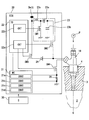
- FIG. 1 is a schematic diagram illustrating a fuel injection control device according to a first embodiment of the present disclosure and a fuel injection system including the device.
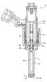
- Sectional drawing which shows the whole structure of a fuel injection valve in 1st Embodiment.
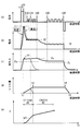
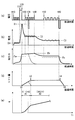
- the injection control is performed in the first embodiment, the change in the applied voltage to the coil, the coil current, the electromagnetic attractive force, and the lift amount with the passage of time is shown, and the relationship between the energization time and the injection amount is shown.
- Figure. The figure which shows that the characteristic line showing the relationship between electricity supply time and injection quantity becomes a different shape according to coil temperature.
- the change in voltage applied to the coil, coil current, electromagnetic attraction force and lift amount with time is shown, and the relationship between energization time and injection amount is shown.
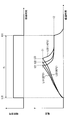
- FIG. The figure which shows the peak appearance range in 5th Embodiment of this indication.
- a fuel injection valve 10 shown in FIG. 1 is mounted on an internal combustion engine (gasoline engine) and directly injects fuel into the combustion chamber 2 of the internal combustion engine. Specifically, a mounting hole 4 for inserting the fuel injection valve 10 is formed in the cylinder head 3 forming the combustion chamber 2. The fuel supplied to the fuel injection valve 10 is pumped by the fuel pump P, and the fuel pump P is driven by the rotational driving force of the internal combustion engine.
- the fuel injection valve 10 includes a body 11, a valve body 12, a coil 13, a fixed core 14, a movable core 15, an injection hole body 17, and the like.
- the body 11 is made of a metallic magnetic material so that the fuel passage 11a is formed inside.
- the body 11 houses the valve body 12, the fixed core 14, and the movable core 15, and holds the injection hole body 17.
- the injection hole body 17 is formed with a seating surface 17b on which the valve body 12 is seated and seated, and an injection hole 17a for injecting fuel.
- the valve body 12 is closed so that the seat surface 12a formed on the valve body 12 is seated on the seating surface 17b, the fuel injection from the injection hole 17a is stopped.
- the valve element 12 is opened (lifted up) so as to separate the seat surface 12a from the seating surface 17b, fuel is injected from the injection hole 17a.
- the fixed core 14 is formed in a cylindrical shape with a metal magnetic material, and forms a fuel passage 14a inside the cylinder.
- the movable core 15 is formed in a disk shape from a metal magnetic material, and is disposed opposite the fixed core 14 so as to have a predetermined gap with the fixed core 14 when the coil 13 is not energized.
- the fixed core 14 and the movable core 15 form a magnetic circuit serving as a path for magnetic flux generated by energization of the coil 13.
- a through-hole 15a is formed in the movable core 15, and the valve body 12 is slidably attached to the movable core 15 by being inserted and disposed in the through-hole 15a. ing.
- a locking portion 12 d is formed at the end of the valve body 12 on the side opposite to the injection hole.
- the main spring SP1 is disposed on the side opposite to the injection hole of the valve body 12, and the sub spring SP2 is disposed on the injection hole side of the movable core 15. These springs SP1 and SP2 are coiled and elastically deformed in the direction of the central axis C.
- the elastic force (main elastic force Fs1) of the main spring SP1 is applied to the valve body 12 on the valve closing side.
- the elastic force (sub elastic force Fs2) of the sub spring SP2 is applied to the movable core 15 on the valve opening side.
- the valve body 12 is sandwiched between the main spring SP1 and the seating surface 17b, and the movable core 15 is sandwiched between the sub spring SP2 and the locking portion 12d. Then, the elastic force Fs2 of the subspring SP2 is transmitted to the locking portion 12d via the movable core 15, and is given to the valve body 12 in the valve opening direction. Therefore, it can be said that the elastic force Fs obtained by subtracting the sub elastic force Fs2 from the main elastic force Fs1 is applied to the valve body 12 in the valve closing direction.
- the electronic control unit (ECU) 20 includes a microcomputer 21, an integrated IC 22, a booster circuit 23, switching elements SW2, SW3, SW4, and the like.
- the ECU 20 provides a fuel injection control device that controls the fuel injection amount by controlling the operation of the fuel injection valve 10.
- the ECU 20 and the fuel injection valve 10 provide a fuel injection system that injects an optimal amount of fuel.
- the microcomputer 21 includes a central processing unit, a nonvolatile memory, a volatile memory, and the like, and calculates a target fuel injection amount and a target injection start timing based on the load and engine speed of the internal combustion engine.
- the injection characteristic (Ti-q characteristic line) indicating the relationship between the energization time Ti and the injection amount q is obtained by testing in advance, and the energization time Ti to the coil 13 is controlled according to the injection characteristic.
- the injection amount q is controlled.
- Reference numeral t10 in FIG. 3A to be described later indicates the start time of the energization time
- reference numeral t60 indicates the end time of the energization time.
- the integrated IC 22 includes an injection drive circuit 22a that controls the operation of the switching elements SW2, SW3, and SW4, and a charging circuit 22b that controls the operation of the booster circuit 23. These circuits 22 a and 22 b operate based on the injection command signal output from the microcomputer 21.
- the injection command signal is a signal for instructing the energization state of the coil 13 of the fuel injection valve 10, and is executed by the microcomputer 21 based on the target injection amount and target injection start timing described above and the coil current detection value I described later. Is set.
- the injection command signal includes an injection signal, a boost signal, and a battery signal, which will be described later.
- the booster circuit 23 includes a coil 23a, a capacitor 23b, a diode 23c, and a switching element SW1.
- the charging circuit 22b controls the switching element SW1 so that the switching element SW1 is repeatedly turned on and off, the battery voltage applied from the battery terminal Batt is boosted (boosted) by the coil 23a and stored in the capacitor 23b. .
- the voltage of the electric power boosted and stored in this way corresponds to the “boost voltage”.
- the injection drive circuit 22a turns on both the switching elements SW2 and SW4, a boost voltage is applied to the coil 13 of the fuel injection valve 10.
- the switching element SW2 is turned off and the switching element SW3 is turned on, the battery voltage is applied to the coil 13 of the fuel injection valve 10.
- the switching elements SW2, SW3, SW4 are turned off.
- the diode 24 is for preventing the boost voltage from being applied to the switching element SW3 when the switching element SW2 is turned on.
- the shunt resistor 25 is for detecting a current flowing through the switching element SW4, that is, a current flowing through the coil 13 (coil current).
- the microcomputer 21 is based on the voltage drop amount generated in the shunt resistor 25 as described above.
- the coil current detection value I is detected.
- the electromagnetic attractive force when saturated and reaches the maximum value is referred to as a static attractive force Fb.
- the electromagnetic attraction force necessary for the valve body 12 to start the valve opening operation is referred to as a necessary valve opening force Fa.
- the higher the pressure of the fuel supplied to the fuel injection valve 10 the greater the electromagnetic attraction force (required valve opening force) required for the valve body 12 to start the valve opening operation.
- the required valve opening force increases according to various situations such as when the viscosity of the fuel is high. Therefore, the maximum value of the required valve opening force when the situation where the required valve opening force is maximized is defined as the required valve opening force Fa.
- FIG. 3 (a) shows a voltage waveform applied to the coil 13 when the valve element 12 is opened once and fuel injection is performed.
- the solid line shows the waveform when the coil 13 is at room temperature
- the dotted line in the figure shows the waveform when the coil 13 is at high temperature.
- the boost voltage is applied to start energization at the voltage application start time (see t10) commanded by the injection command signal. Then, the coil current increases with the start of energization (see FIG. 3B). The energization is turned off when the coil current detection value I reaches the first target value I1 (see t20). In short, control is performed so that the coil current is increased to the first target value I1 by applying the boost voltage by the first energization.
- the microcomputer 21 during such control corresponds to the “rise controller 21a”. Further, the first target value I1 corresponds to a “predetermined threshold value”.
- energization by the battery voltage is controlled so that the coil current is maintained at the second target value I2 set to a value lower than the first target value I1.
- the average value of the fluctuating coil current is changed to the second target value I2 by repeatedly turning on and off the battery voltage so that the deviation between the coil current detection value I and the second target value I2 is within a predetermined range.
- the duty is controlled so that The microcomputer 21 during such control corresponds to the “constant current control unit 21b”.
- the second target value I2 is set to a value such that the static suction force Fb is equal to or greater than the required valve opening force Fa.
- the energization by the battery voltage is controlled so that the coil current is maintained at the third target value I3 set to a value lower than the second target value I2.
- the average value of the fluctuating coil current is changed to the third target value I3 by repeatedly turning on and off the battery voltage so that the deviation between the coil current detection value I and the third target value I3 is within a predetermined range.
- the duty is controlled so that The microcomputer 21 during such control corresponds to the “hold control unit 21c”.
- the electromagnetic attractive force continues to increase during a period from the start of energization, that is, the increase control start time (t10) to the constant current control end time (t40). Note that the rate of increase of the electromagnetic attractive force is slower in the constant current control period than in the increase control period.
- the suction force is held at a predetermined value.
- the third target value I3 is set so that the predetermined value is higher than the valve opening holding force Fc required to hold the valve open state.
- the valve opening holding force Fc is smaller than the required valve opening force Fa.
- the injection signal included in the injection command signal is a pulse signal for instructing the energization time Ti, and the pulse-on time is set at a time (t10) earlier than the target injection start time by a predetermined injection delay time.
- the pulse-off timing is set at the energization end timing (t60) when the energization time Ti has elapsed since the pulse was turned on.
- the switching element SW4 operates according to this injection signal.
- the boost signal included in the injection command signal is a pulse signal that commands on / off of energization by the boost voltage, and turns on at the same time as the pulse of the injection signal is turned on. Thereafter, the boost signal is turned on until the coil current detection value I reaches the first target value I1. Thereby, the boost voltage is applied to the coil 13 in the increase control period.
- the battery signal included in the injection command signal is turned on at the constant current control start time t30. Thereafter, the battery signal is repeatedly turned on and off so as to perform feedback control so that the coil current detection value I is held at the second target value I2 until the elapsed time from the start of energization reaches a predetermined time. Thereafter, the battery signal is repeatedly turned on and off so as to perform feedback control so that the coil current detection value I is held at the third target value I3 during the period until the pulse of the injection signal is turned off.
- the switching element SW3 operates according to this battery signal.
- the valve body 12 starts the valve opening operation when the injection delay time has elapsed from the start of energization (t10), that is, at the time t1 when the suction force reaches the required valve opening force Fa. .
- the symbol t3 in the figure indicates the timing at which the valve body 12 reaches the maximum valve opening position (full lift position), and the symbol t4 in the figure indicates the timing at which the valve body 12 starts to close.
- the valve body 12 starts the valve closing operation at the time when the delay time has elapsed from the energization end timing (t60), that is, at the time t4 when the suction force is reduced to the valve opening holding force Fc.
- a voltage obtained by reversing positive and negative is applied to the coil 13 simultaneously with the injection end command timing.
- the coil current flows in the direction opposite to the coil current during the energization time Ti (t10 to t60), and the valve closing speed of the valve body 12 is increased. That is, the valve closing delay time from the energization end timing t60 to the time t5 when the valve body 12 is seated and closes can be shortened.
- Such reverse voltage application after the energization end timing t60 is not included in the energization time Ti calculated by the energization time calculation unit S40 described later, and is not included in the energization time Ti of the Ti-q characteristic line.
- FIG. 3 (e) represents a characteristic line representing the relationship between the energization time Ti and the injection amount q, and the elapsed time (a) to (d) and the energization time Ti are shown together.
- the time point t31 (see FIG. 3A) during which the coil current is being held at the second target value I2 is set as the end time of the energization time to turn off the pulse of the injection signal.
- the suction force starts decreasing and the valve body 12 starts the valve closing operation.
- the injection amount in this case is the injection amount q31 corresponding to t31 in the characteristic line shown in FIG.
- the pressure (fuel pressure Pc) of the fuel supplied to the fuel injection valve 10 is detected by the fuel pressure sensor 30 shown in FIG.
- the ECU 20 determines whether or not to perform the above-described constant current control according to the fuel pressure Pc detected by the fuel pressure sensor 30. For example, when the fuel pressure Pc is equal to or greater than a predetermined threshold value Pth, constant current control is permitted. On the other hand, when the fuel pressure Pc is less than the predetermined threshold value Pth, the electromagnetic attractive force required to start the valve opening operation is small, so the constant current control is not performed and the hold control is performed after the ascent control. To do.
- the slope of the Ti-q characteristic line becomes small.
- the region in the period t1 to t3 is called “partial region A1”, and the region after t3 is called “full lift region A2”. That is, in the partial region A1, the valve body 12 starts the valve closing operation before reaching the maximum valve opening position, and a small amount of fuel (see symbol q31) is injected.
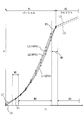
- FIG. 4 is a test result showing the shape of the Ti-q characteristic line that varies with temperature.
- the characteristic line L1 in the figure shows the result of testing at room temperature.
- the characteristic line L2 shows the result of testing by passing a current through the coil 13 through a resistance corresponding to 80 ° C.
- a characteristic line L3 shows a test result when a current is passed through the coil 13 through a resistance corresponding to 140 ° C.
- the inventors obtained the following knowledge. That is, in the partial region A1, in the energization time region (decrease region) shorter than the peak appearance range W1 described later, the injection amount with respect to the energization time decreases as the coil temperature increases. On the other hand, in the partial region A1, in the energization time region (increase region) longer than the peak appearance range W1, the injection amount with respect to the energization time increases as the coil temperature increases.
- FIG. 5 shows the results of testing and measuring the coil current change (current waveform) caused by the control of the ascent control unit 21a and the constant current control unit 21b.
- the energization is terminated at time t31 when the coil current is held at the second target value I2 by the constant current control unit 21b, and the energization time Ti corresponding to the injection amount in the partial area A1 is set. .
- the current waveform L10 in the figure shows the result of testing at room temperature.
- a current waveform L20 shows a test result when a current is passed through the coil 13 through a resistor corresponding to 80 ° C.
- a current waveform L30 shows a test result when a current is passed through the coil 13 through a resistance corresponding to 140 ° C.
- Symbols t21, t22, and t23 in the figure indicate times when the current reaches a peak value when the increase control unit 21a is terminated and the application of the boost voltage is stopped.
- the higher the coil temperature the longer the time until the current reaches the first target value I1, and the peak value appears later. This is because the higher the coil temperature, the higher the resistance of the coil 13. Therefore, if energization is terminated before the appearance times t21, t22, and t23 of peak values, the injection amount for the energization time Ti decreases as the coil temperature increases. That is, in the energization time Ti on the side shorter than the peak appearance range W1 in FIG. 4, the low-temperature characteristic line L1 is positioned above the high-temperature characteristic line L3 among the three characteristic lines L1, L2, and L3. .
- the characteristic line L3 at high temperature of the three characteristic lines L1, L2, and L3 is higher than the characteristic line L1 at low temperature in the energization time Ti longer than the peak appearance range W1 in FIG. Is also located on the upper side. That is, when the energization time Ti is set shorter than the peak appearance range W1, the injection amount with respect to the energization time decreases as the coil temperature increases. On the other hand, when the energization time Ti is set longer than the peak appearance range W1, the injection amount with respect to the energization time increases as the coil temperature increases. That is, the increase and decrease depending on the temperature of the injection amount with respect to the energization time Ti are switched at the peak appearance range W1.
- the energization time Ti is set in the region indicated by reference numeral B1 in FIG. 4 so that the end times t31 and t60 of the energization time Ti are later than the peak appearance range W1.
- the procedure for calculating the energization time Ti will be described with reference to FIG.
- FIG. 6 is a flowchart showing a procedure of processing that the microcomputer 21 repeatedly executes at predetermined time intervals in accordance with a program.
- step S10 the rotational speed NE and load per unit time of the internal combustion engine at the present time are acquired.
- the load include a depression amount of an accelerator pedal operated by a driver, an intake air flow rate or an intake negative pressure.
- a target value (total target injection amount) of the total amount of fuel injected into one cylinder during one combustion cycle is calculated based on the acquired rotational speed NE and load.
- the calculated total number of injections in one combustion cycle, the number of divisions of the total target injection amount, and the target injection amount of fuel injected by one opening of the fuel injection valve 10 are calculated. Set based on the target injection amount. The sum of the target injection amounts relating to the respective injections divided in one combustion cycle matches the total target injection amount.
- step S40 energization time Ti is calculated for each set target injection amount. Specifically, first, in step S41, a base value of the energization time Ti corresponding to the target injection amount is set. Specifically, in the case where the operating temperature range is from ⁇ 30 ° C. to 200 ° C., a map related to the Ti-q characteristic line at the center temperature is stored in the microcomputer 21 in advance. And based on the said map, the value of the electricity supply time Ti with respect to the injection quantity is set as a base value.
- the temperature of the coil 13 is estimated.
- the time required for the coil current to increase to the first target value I1 by the increase controller 21a has a high correlation with the coil temperature. Therefore, the above time is detected, and the coil temperature is estimated based on the time.
- a correction value for the base value of the energization time Ti is calculated based on the estimated coil temperature.
- the injection amount increases as the temperature rises as shown in FIG. 4. Therefore, the correction value is a value in which the base value is corrected to be shorter as the temperature is higher. Is set.
- a value obtained by adding the correction value calculated in step S43 to the base value of the energization time Ti set in step S41 is calculated as the energization time Ti.
- the correction value is calculated to correct the energization time Ti.
- the change in the injection amount that occurs according to the temperature is extremely small. Therefore, when the base value is the full lift region A2, the correction value is not calculated and corrected.
- step S30 the target injection amount and the number of divisions are set so that the end time t31 of the energization time Ti set in step S40 is later than the peak appearance range W1. That is, by adjusting the number of divisions, the target injection amount is set so that the end timing t31 is later than the peak appearance range W1.
- the resistance value, boost voltage, and first target value I1 of the coil 13 are set so that the minute injection amount in the partial region A1 can be included in the target injection amount setting range. That is, as the resistance value of the coil 13 is larger, the boost voltage is smaller, or the first target value I1 is smaller, the peak appearance range W1 is positioned on the longer energization time Ti side. Then, there is a case where the partial area A1 does not exist on the side later than the peak appearance range W1. The resistance value of the coil 13, the boost voltage, and the first target value I1 are set so as not to fall into such a situation.
- the microcomputer 21 executing the process of step S40 corresponds to the “energization time calculating unit”, and the microcomputer 21 executing the process of step S30 is the “target injection amount setting unit”. Equivalent to.
- the target injection amount is set in step S30 of FIG. 6 so that the end time t31 of the energization time Ti falls outside the peak appearance range W1. For this reason, when the temperature of the base value of the energization time Ti corresponding to the target injection amount is temperature-corrected, it is uniquely specified whether the correction should be increased or decreased as the temperature increases. Therefore, it is not necessary to switch between the case of increasing correction and the case of decreasing correction as the temperature is higher for the same target injection amount. Therefore, since the concern of reversing the increase / decrease in the correction can be solved, the fuel injection amount can be controlled with high accuracy.
- the target injection amount is set so that the end time t31 of the energization time Ti is a time later than the peak appearance range W1.
- the peak appearance range W1 needs to be set sufficiently late. Then, it is necessary to increase the resistance value of the coil 13, lower the boost voltage, and lower the first target value I1. Then, the valve opening response delay time from when the energization is started until the valve body 12 starts the valve opening operation becomes long, and the response of the operation of the fuel injection valve 10 is deteriorated.
- the end time t31 of the energization time Ti is set to a time later than the peak appearance range W1, and thus the above-described problem of deterioration in responsiveness can be avoided.
- the following conditions are satisfied so that the minute injection amount in the partial region A1 can be included in the target injection amount setting range while satisfying the condition that the end timing t31 deviates from the peak appearance range W1.
- a value is set. That is, the resistance value of the coil 13 is set sufficiently small, the boost voltage is set sufficiently high, and the first target value I1 (that is, the current peak value) is set sufficiently high. According to this, in the partial area A1, the amount of variation due to the temperature of the characteristic lines L1, L2, and L3 can be reduced. Therefore, the accuracy of temperature correction in the partial area A1 can be improved.
- the peak appearance range W1 can also be said to be a change point appearance range that is a range in which the change point Pf of the electromagnetic attractive force can appear in the operating temperature range. Therefore, setting the target injection amount so that the end time t31 of the energization time Ti is outside the peak appearance range W1 means that the target injection is such that the end time t31 is outside the change point appearance range. In other words, the amount can be set.
- the target injection amount is set in step S30 of FIG. 6 so that the end time t31 of the energization time Ti is outside the peak appearance range.
- the target injection amount is set so that the end time t31 of the energization time Ti falls outside the cross point appearance ranges W2 and W3 described below.
- cross points P1 and P2 points where characteristic lines L1, L2, and L3 intersect with each other are referred to as cross points P1 and P2.
- the cross point between the characteristic line L1 and the characteristic line L2, the cross point between the characteristic line L1 and the characteristic line L3, and the cross point between the characteristic line L2 and the characteristic line L3 are the same positions (positions P1 and P2). Is shown in FIG. However, strictly speaking, these cross points appear at different positions.
- the ranges where the cross points P1, P2 can appear according to the operating temperature range of the coil 13 are the cross point appearance ranges W2, W3.
- a specific example of the use temperature range of the coil 13 is a use range of ⁇ 30 ° C. to 200 ° C.
- the range from which the end time t31 is removed is one place of the peak appearance range W1
- the cross point appearance ranges W2 and W3 exist at two places, and the end time There are two ranges for removing t31.
- the energization time Ti is set in the areas indicated by reference numerals B2 and B3 in FIG.
- One cross point appearance range W2 partially overlaps with the peak appearance range W1.
- One cross point appearance range W3 includes a boundary between the partial area A1 and the full lift area A2.
- the target injection amount is set so that the end time t31 of the energization time Ti is a time deviating from the cross point appearance ranges W2 and W3. For this reason, when the temperature of the base value of the energization time Ti corresponding to the target injection amount is temperature-corrected, it is uniquely specified whether the correction should be increased or decreased as the temperature increases. Therefore, it is not necessary to switch between the case of increasing correction and the case of decreasing correction as the temperature is higher for the same target injection amount. Therefore, since the concern of reversing the increase / decrease in the correction can be solved, the fuel injection amount can be controlled with high accuracy.
- the minute injection amount in the partial region A1 can be included in the target injection amount setting range while satisfying the condition that the end timing t31 is out of the cross point appearance ranges W2 and W3.
- the following values are set. That is, the resistance value of the coil 13 is set sufficiently small, the boost voltage is set sufficiently high, and the first target value I1 (that is, the current peak value) is set sufficiently high. According to this, in the partial area A1, the amount of variation due to the temperature of the characteristic lines L1, L2, and L3 can be reduced. Therefore, the accuracy of temperature correction in the partial area A1 can be improved.
- the microcomputer 21 provides a precharge control unit 21d described below. That is, the microcomputer 21 controls the integrated IC 22 so as to perform a precharge in which the battery voltage is applied to the coil 13 prior to the application of the boost voltage by the increase control unit 21a. The microcomputer 21 under such control corresponds to the “precharge control unit 21d”.
- the integrated IC 22 controlled by the microcomputer 21 to perform the precharge turns on the switching element SW4 and turns on and off the switching element SW4 so that the coil current is maintained at the fourth target value I4 (FIG. 9).
- the fourth target value I4 is set to a value smaller than the third target value I3 (see FIG. 9B).
- the precharge control for applying the battery voltage to the coil 13 is started at the time t0 set a predetermined time before the time t10 when the rising control starts. Thereby, prior to the start of the raising control, the suction force starts to rise (see FIG. 9C).
- the boost voltage application period required to increase the coil current to the first target value I1 in the increase control can be shortened. Therefore, the amount of heat generated by the booster circuit 23 can be reduced, and the risk of thermal damage to the ECU 20 can be reduced.
- the target injection amount is set so that the end time t31 of the energization time Ti falls outside the peak appearance range W1 as in the first embodiment.
- the precharge control is performed, the time required to increase the coil current to the first target value I1 by the increase control is shortened. Therefore, the appearance time of the peak value of the coil current is advanced, and the peak appearance range W1 is shifted to the early side. Therefore, the setting area B1 shown in FIG. 4 can be expanded early, and the minimum value of the energization time Ti that can be set can be reduced.
- the fear of reversing the increase / decrease in the correction is solved, the fuel injection amount can be controlled with high accuracy, and the minimum target injection amount that can be set is reduced. become able to.
- the target injection amount is set so that the end time t31 of the energization time Ti is out of the peak appearance range W1 after the precharge control unit 21d is provided.
- the precharge control unit 21d is provided in the same manner as in the third embodiment, and the end timing t31 of the energization time Ti is set to the cross point appearance range W2 in the same manner as in the second embodiment.
- the target injection amount is set so as to be out of W3.
- the present embodiment can provide the same effects as those of the third embodiment. That is, it is possible to control the fuel injection amount with high accuracy by eliminating the concern that the increase / decrease in the correction is reversed, and to reduce the minimum target injection amount that can be set.
- the setting of the resistance value of the coil 13, the boost voltage, and the first target value I1 is the same. Therefore, the characteristic lines L1, L2, and L3 shown in FIG. 4 are the same as the characteristic lines L1, L2, and L3 shown in FIG.
- the setting of the resistance value of the coil 13, the boost voltage, and the first target value I1 is changed.
- the energization time Ti is set in the region indicated by reference sign B1 in FIG. 4 so that the end time t31 of the energization time Ti is a time later than the peak appearance range W1. .
- the energization time Ti is set in both the region earlier than the peak appearance range W4 (see symbol B4) and the later region (see symbol B5).
- the slower area B5 is set so as not to include the partial area A1. Therefore, in the partial area A1, the end time t31 is set in the area B4, and in the full lift area A2, the end time t60 is set in the area B5.
- the resistance value, boost voltage, and first target value I1 of the coil 13 are set so that the peak appearance ranges W1 and W4 are located in the partial region A1.
- the resistance value, the boost voltage, and the first target value I1 of the coil 13 may be set so that the peak appearance ranges W1 and W4 are located in the full lift region A2.
- a feedback control unit that includes an injection amount estimation unit that estimates the amount of actual injection, and that learns the deviation between the estimated actual injection amount and the target injection amount and feeds back to the next energization time Ti setting May be provided.
- the target injection amount is set such that the end times t31 and t60 of the energization time Ti deviate from the peak appearance ranges W1 and W4 or the cross point appearance ranges W2 and W3. May be set.
- the injection amount estimation unit the actual injection amount is detected based on the detection result and the fuel pressure Pc detected by the fuel pressure sensor 30 when the valve body 12 is actually opened and closed. Is estimated.
- the time point (t20) when the coil current reaches the first target value I1 is the peak appearance time.
- switching from the boost voltage to the battery voltage may be continued, and the increased coil current may be held for the predetermined time with the first target value I1. In this case, the time when the boost voltage is switched to the battery voltage corresponds to the peak appearance time.
- the fuel injection valve 10 is attached to the cylinder head 3 as shown in FIG. 1, but the fuel injection valve attached to the cylinder block may be applied.
- the fuel injection valve 10 mounted on the ignition type internal combustion engine gasoline engine
- the fuel injection valve mounted on the compression ignition type internal combustion engine diesel engine
- the fuel injection valve which injects a fuel directly to the combustion chamber 2 is made into control object, it is good also considering the fuel injection valve which injects fuel into an intake pipe as control object.
Landscapes
- Engineering & Computer Science (AREA)
- Chemical & Material Sciences (AREA)
- Combustion & Propulsion (AREA)
- Mechanical Engineering (AREA)
- General Engineering & Computer Science (AREA)
- Physics & Mathematics (AREA)
- Electromagnetism (AREA)
- Fuel-Injection Apparatus (AREA)
- Electrical Control Of Air Or Fuel Supplied To Internal-Combustion Engine (AREA)
Abstract
A fuel injection control device equipped with: an energization time calculation unit that calculates a coil energization time in accordance with a target injection amount; and an increase control unit that applies a boost voltage to the coil in conjunction with the start of energization, thereby increasing the current flowing in the coil to a prescribed threshold value. When the peak appearance range (W1) is defined as the range during which the moment (that is, the moment when the current increases to the threshold value and thereby reaches the peak value) can appear in accordance with the usage temperature of the coil, the target injection amount is set such that the energization time (Ti) ends outside of the peak appearance range (W1).
Description
本出願は、2013年11月21日に出願された日本出願番号2013-241238号に基づくもので、ここにその記載内容を援用する。
This application is based on Japanese Patent Application No. 2013-241238 filed on November 21, 2013, the contents of which are incorporated herein by reference.
本開示は、燃料噴射弁のコイルへの通電時間を制御することで燃料の噴射量を制御する、燃料噴射制御装置および燃料噴射システムに関する。
The present disclosure relates to a fuel injection control device and a fuel injection system that control a fuel injection amount by controlling a current-carrying time to a coil of a fuel injection valve.
一般的な燃料噴射弁は、コイルへ通電して生じた電磁吸引力により弁体を開弁作動させる構造である。そして、従来の燃料噴射制御装置は、コイルへの通電時間を制御することで弁体の開弁時間を制御し、ひいては1回の開弁で噴射される量を制御する。詳細には、先ず、昇圧回路により昇圧されたブースト電圧をコイルに印加して、電磁吸引力を即座に上昇させる。その後、コイルを流れる電流(コイル電流)が所定の閾値にまで上昇した時点でブースト電圧の印加を停止させ、その後、目標噴射量に対応する通電時間に達した時点でコイルへのバッテリ電圧の印加を停止させる。
A general fuel injection valve has a structure in which a valve element is opened by electromagnetic attraction generated by energizing a coil. And the conventional fuel-injection control apparatus controls the valve opening time of a valve body by controlling the energization time to a coil, and also controls the quantity injected by one valve opening. Specifically, first, the boost voltage boosted by the booster circuit is applied to the coil, and the electromagnetic attractive force is immediately increased. Thereafter, the application of the boost voltage is stopped when the current flowing through the coil (coil current) rises to a predetermined threshold, and then the battery voltage is applied to the coil when the energization time corresponding to the target injection amount is reached. Stop.
コイル温度が高くなると電気抵抗が大きくなる。そのため、通電時間と噴射量との関係を表す特性線の形状はコイル温度に応じて異なってくる。そこで本発明者らは、目標噴射量に対応する通電時間を、コイル温度に応じて補正(温度補正)することを検討した。
The electrical resistance increases as the coil temperature increases. Therefore, the shape of the characteristic line representing the relationship between the energization time and the injection amount varies depending on the coil temperature. Therefore, the present inventors have considered correcting the energization time corresponding to the target injection amount according to the coil temperature (temperature correction).
ここで、本発明者らが実施した試験により、特性線には以下の減少領域および増加領域の両方が含まれていることが明らかになった。減少領域では、コイル温度が高いほど通電時間に対する噴射量が減少する。増加領域では、コイル温度が高いほど噴射量が増加する。そのため、目標噴射量に対応する通電時間が、減少領域および増加領域のいずれであるかを判別し、その判別結果に応じて温度補正の増減を逆にすることを要する。
Here, a test conducted by the present inventors revealed that the characteristic line includes both the following decrease region and increase region. In the decrease region, the injection amount with respect to the energization time decreases as the coil temperature increases. In the increase region, the injection amount increases as the coil temperature increases. Therefore, it is necessary to determine whether the energization time corresponding to the target injection amount is in the decrease region or the increase region, and to reverse increase / decrease in temperature correction according to the determination result.
しかしながら、例えば、想定していた特性線が実際の特性線に対して僅かにずれているだけで、減少領域と増加領域の判別結果が異なってくる。そして、上記判別を誤ると、温度補正の増減が逆に為されてしまうので、実際の噴射量が目標噴射量から乖離する側に補正される懸念が生じる。
However, for example, even if the assumed characteristic line is slightly shifted from the actual characteristic line, the determination result of the decrease area and the increase area differs. If the determination is made incorrectly, the temperature correction is increased or decreased in reverse, and there is a concern that the actual injection amount is corrected to the side deviating from the target injection amount.
本開示は、噴射量を高精度で制御できるようにした燃料噴射制御装置および燃料噴射システムを提供することにある。
The present disclosure is to provide a fuel injection control device and a fuel injection system capable of controlling an injection amount with high accuracy.
本開示の一態様によれば、燃料噴射制御装置は、コイルへ通電して生じた電磁吸引力により弁体を開弁作動させて、内燃機関の燃焼に用いる燃料を噴射する燃料噴射弁に適用される。
According to one aspect of the present disclosure, a fuel injection control device is applied to a fuel injection valve that injects fuel used for combustion of an internal combustion engine by opening a valve body by electromagnetic attraction generated by energizing a coil. Is done.
そして、燃料噴射弁の1回の開弁で噴射される燃料の目標噴射量を設定する目標噴射量設定部と、目標噴射量に応じたコイルへの通電時間を算出する通電時間算出部と、バッテリ電圧を昇圧する昇圧回路と、通電時間の開始に伴い、昇圧回路により昇圧されたブースト電圧をコイルへ印加して、コイルを流れる電流を所定の閾値まで上昇させる上昇制御部と、を備え、閾値まで上昇して電流がピーク値になる時期が、コイルの使用温度範囲に応じて出現し得る範囲をピーク出現範囲と呼ぶ場合に、通電時間の終了時期がピーク出現範囲から外れた時期になるように、目標噴射量設定部は目標噴射量を設定することを特徴とする。
A target injection amount setting unit that sets a target injection amount of fuel injected by one opening of the fuel injection valve; an energization time calculating unit that calculates an energization time to the coil according to the target injection amount; A booster circuit that boosts the battery voltage, and a boost control unit that applies a boost voltage boosted by the booster circuit to the coil as the energization time starts, and raises the current flowing through the coil to a predetermined threshold; When the current rises to the threshold and the current reaches its peak value, when the range that can appear according to the operating temperature range of the coil is called the peak appearance range, the end time of the energization time is out of the peak appearance range. As described above, the target injection amount setting unit sets the target injection amount.
通電時間と噴射量との関係を表す特性線には、高温であるほど噴射量が増加する増加領域と、高温であるほど噴射量が減少する減少領域とが含まれている。そして本発明者らは、「増加領域と減少領域との境界がピーク出現範囲に存在する」との知見を得た。
The characteristic line representing the relationship between the energization time and the injection amount includes an increasing region where the injection amount increases as the temperature increases, and a decreasing region where the injection amount decreases as the temperature increases. The present inventors have obtained the knowledge that “the boundary between the increase region and the decrease region exists in the peak appearance range”.
上記開示では、通電時間の終了時期をピーク出現範囲から外れた時期にしている。そのため、目標噴射量に対応する通電時間を温度に応じて補正するにあたり、高温であるほど増加補正するべきか減少補正するべきかが特定されるようになる。よって、同一の目標噴射量に対して、高温であるほど増加補正する場合と減少補正する場合とに切り替えることを不要にできる。したがって、コイル温度に応じて通電時間を補正するにあたり、補正の増減を逆にしてしまう懸念を解消できる。そのため、コイル温度を考慮した特性線に基づいて燃料の噴射量を高精度で制御できるようになる。
In the above disclosure, the end time of the energization time is set to a time outside the peak appearance range. Therefore, when the energization time corresponding to the target injection amount is corrected according to the temperature, it is specified whether the correction should be increased or decreased as the temperature is higher. Therefore, it is not necessary to switch between the case of increasing correction and the case of decreasing correction as the temperature is higher for the same target injection amount. Therefore, when correcting the energization time according to the coil temperature, the concern of reversing the increase / decrease in correction can be solved. Therefore, the fuel injection amount can be controlled with high accuracy based on the characteristic line considering the coil temperature.
また、本開示の他の態様によれば、燃料噴射制御装置は、燃料噴射弁の1回の開弁で噴射される燃料の目標噴射量を設定する目標噴射量設定部と、目標噴射量に応じたコイルへの通電時間を算出する通電時間算出部と、バッテリ電圧を昇圧する昇圧回路と、通電時間の開始に伴い、昇圧回路により昇圧されたブースト電圧をコイルへ印加して、コイルを流れる電流を所定の閾値まで上昇させる上昇制御部と、を備える。 通電時間と噴射量との関係を表す特性線であってコイルの使用温度毎に異なる特性線が互いに交差する点をクロス点と呼び、クロス点がコイルの使用温度範囲に応じて出現し得る範囲をクロス点出現範囲と呼ぶ場合に、通電時間の終了時期がクロス点出現範囲から外れた時期になるように、目標噴射量設定部は目標噴射量を設定する。
According to another aspect of the present disclosure, the fuel injection control device includes a target injection amount setting unit that sets a target injection amount of fuel that is injected by one opening of the fuel injection valve, and a target injection amount. An energization time calculation unit that calculates the energization time to the corresponding coil, a booster circuit that boosts the battery voltage, and a boost voltage boosted by the booster circuit with the start of the energization time is applied to the coil to flow through the coil A rise control unit that raises the current to a predetermined threshold value. A characteristic line representing the relationship between the energization time and the injection amount, and a point where different characteristic lines intersect at each coil operating temperature is called a cross point, and the range where the cross point can appear according to the coil operating temperature range Is called the cross point appearance range, the target injection amount setting unit sets the target injection amount so that the end time of the energization time falls outside the cross point appearance range.
上述した特性線の増加領域と減少領域との境界は、コイルの使用温度毎に異なる特性線が互いに交差するクロス点に相当する。そして上記開示では、通電時間の終了時期をクロス点出現範囲から外れた時期にしている。そのため、目標噴射量に対応する通電時間を温度に応じて補正するにあたり、高温であるほど増加補正するべきか減少補正するべきかが特定されるようになる。よって、同一の目標噴射量に対して、高温であるほど増加補正する場合と減少補正する場合とに切り替えることを不要にできる。したがって、コイル温度に応じて通電時間を補正するにあたり、補正量の増減を逆にしてしまう懸念を解消できる。そのため、コイル温度を考慮した特性線にしたがって、燃料の噴射量を高精度で制御できるようになる。
The boundary between the increasing region and the decreasing region of the characteristic line described above corresponds to a cross point where characteristic lines that differ for each operating temperature of the coil intersect each other. In the above disclosure, the end time of the energization time is set to a time out of the cross point appearance range. Therefore, when the energization time corresponding to the target injection amount is corrected according to the temperature, it is specified whether the correction should be increased or decreased as the temperature is higher. Therefore, it is not necessary to switch between the case of increasing correction and the case of decreasing correction as the temperature is higher for the same target injection amount. Therefore, in correcting the energization time according to the coil temperature, it is possible to eliminate the concern of reversing the correction amount. Therefore, the fuel injection amount can be controlled with high accuracy according to the characteristic line considering the coil temperature.
本開示についての上記目的およびその他の目的、特徴や利点は、添付の図面を参照しながら下記の詳細な記述により、より明確になる。
本開示の第1実施形態に係る燃料噴射制御装置、およびその装置を備えた燃料噴射システムを示す概要図。
第1実施形態において、燃料噴射弁の全体構造を示す断面図。
第1実施形態にて噴射制御を実施した場合における、コイルへの印加電圧、コイル電流、電磁吸引力およびリフト量の時間経過に伴い生じる変化を示すとともに、通電時間と噴射量との関係を示す図。
通電時間と噴射量との関係を表す特性線が、コイル温度に応じて異なる形状になることを示す図。
時間経過に伴い生じるコイル電流の変化を表す電流波形が、コイル温度に応じて異なる形状になることを示す図。
第1実施形態において、通電時間を算出する手順を示すフローチャート。
本開示の第2実施形態において、クロス点出現範囲を示す図。
本開示の第3実施形態に係る燃料噴射システムを示す概要図。
第3実施形態にて、噴射制御を実施した場合における、コイルへの印加電圧、コイル電流、電磁吸引力およびリフト量の時間経過に伴い生じる変化を示すとともに、通電時間と噴射量との関係を示す図。
本開示の第5実施形態において、ピーク出現範囲を示す図。
The above and other objects, features and advantages of the present disclosure will become more apparent from the following detailed description with reference to the accompanying drawings.
1 is a schematic diagram illustrating a fuel injection control device according to a first embodiment of the present disclosure and a fuel injection system including the device. Sectional drawing which shows the whole structure of a fuel injection valve in 1st Embodiment. In the case where the injection control is performed in the first embodiment, the change in the applied voltage to the coil, the coil current, the electromagnetic attractive force, and the lift amount with the passage of time is shown, and the relationship between the energization time and the injection amount is shown. Figure. The figure which shows that the characteristic line showing the relationship between electricity supply time and injection quantity becomes a different shape according to coil temperature. The figure which shows that the electric current waveform showing the change of the coil electric current which arises with progress of time becomes a different shape according to coil temperature. The flowchart which shows the procedure which calculates energization time in 1st Embodiment. The figure which shows the cross point appearance range in 2nd Embodiment of this indication. The schematic diagram showing the fuel injection system concerning a 3rd embodiment of this indication. In the third embodiment, when injection control is performed, the change in voltage applied to the coil, coil current, electromagnetic attraction force and lift amount with time is shown, and the relationship between energization time and injection amount is shown. FIG. The figure which shows the peak appearance range in 5th Embodiment of this indication.
以下、図面を参照しながら複数の形態を説明する。各形態において、先行する形態で説明した事項に対応する部分には同一の参照符号を付して重複する説明を省略する場合がある。各形態において、構成の一部のみを説明している場合は、構成の他の部分については先行して説明した他の形態を参照し適用することができる。
Hereinafter, a plurality of embodiments will be described with reference to the drawings. In each embodiment, portions corresponding to the matters described in the preceding embodiment may be denoted by the same reference numerals and redundant description may be omitted. In each embodiment, when only a part of the configuration is described, the other configurations described above can be applied to other portions of the configuration.
(第1実施形態)
図1に示す燃料噴射弁10は、内燃機関(ガソリンエンジン)に搭載されており、内燃機関の燃焼室2へ直接燃料を噴射するものである。具体的には、燃焼室2を形成するシリンダヘッド3に、燃料噴射弁10を挿入する取付穴4が形成されている。燃料噴射弁10へ供給される燃料は燃料ポンプPにより圧送され、燃料ポンプPは内燃機関の回転駆動力により駆動する。 (First embodiment)
Afuel injection valve 10 shown in FIG. 1 is mounted on an internal combustion engine (gasoline engine) and directly injects fuel into the combustion chamber 2 of the internal combustion engine. Specifically, a mounting hole 4 for inserting the fuel injection valve 10 is formed in the cylinder head 3 forming the combustion chamber 2. The fuel supplied to the fuel injection valve 10 is pumped by the fuel pump P, and the fuel pump P is driven by the rotational driving force of the internal combustion engine.
図1に示す燃料噴射弁10は、内燃機関(ガソリンエンジン)に搭載されており、内燃機関の燃焼室2へ直接燃料を噴射するものである。具体的には、燃焼室2を形成するシリンダヘッド3に、燃料噴射弁10を挿入する取付穴4が形成されている。燃料噴射弁10へ供給される燃料は燃料ポンプPにより圧送され、燃料ポンプPは内燃機関の回転駆動力により駆動する。 (First embodiment)
A
図2に示すように、燃料噴射弁10は、ボデー11、弁体12、コイル13、固定コア14、可動コア15、噴孔ボデー17等を備えて構成されている。ボデー11は、内部に燃料通路11aが形成されるよう、金属製の磁性材料にて形成されている。ボデー11は、弁体12、固定コア14および可動コア15を内部に収容するとともに、噴孔ボデー17を保持する。
As shown in FIG. 2, the fuel injection valve 10 includes a body 11, a valve body 12, a coil 13, a fixed core 14, a movable core 15, an injection hole body 17, and the like. The body 11 is made of a metallic magnetic material so that the fuel passage 11a is formed inside. The body 11 houses the valve body 12, the fixed core 14, and the movable core 15, and holds the injection hole body 17.
噴孔ボデー17には、弁体12が離着座する着座面17b、および燃料を噴射する噴孔17aが形成されている。弁体12に形成されたシート面12aを着座面17bに着座させるよう弁体12を閉弁作動させると、噴孔17aからの燃料噴射が停止される。シート面12aを着座面17bから離座させるよう弁体12を開弁作動(リフトアップ)させると、噴孔17aから燃料が噴射される。
The injection hole body 17 is formed with a seating surface 17b on which the valve body 12 is seated and seated, and an injection hole 17a for injecting fuel. When the valve body 12 is closed so that the seat surface 12a formed on the valve body 12 is seated on the seating surface 17b, the fuel injection from the injection hole 17a is stopped. When the valve element 12 is opened (lifted up) so as to separate the seat surface 12a from the seating surface 17b, fuel is injected from the injection hole 17a.
固定コア14は、金属製の磁性材料にて円筒形状に形成され、円筒内部に燃料通路14aを形成する。可動コア15は、金属製の磁性材料にて円盤形状に形成されており、コイル13への非通電時には固定コア14と所定のギャップを有するよう、固定コア14に対向配置されている。固定コア14および可動コア15は、コイル13への通電により生じた磁束の通路となる磁気回路を形成する。
The fixed core 14 is formed in a cylindrical shape with a metal magnetic material, and forms a fuel passage 14a inside the cylinder. The movable core 15 is formed in a disk shape from a metal magnetic material, and is disposed opposite the fixed core 14 so as to have a predetermined gap with the fixed core 14 when the coil 13 is not energized. The fixed core 14 and the movable core 15 form a magnetic circuit serving as a path for magnetic flux generated by energization of the coil 13.
コイル13へ通電して固定コア14に電磁吸引力を生じさせると、この電磁吸引力により可動コア15が固定コア14に引き寄せられる。その結果、可動コア15に連結されている弁体12は、後述するメインスプリングSP1の弾性力および燃圧閉弁力に抗してリフトアップ(開弁作動)する。一方、コイル13への通電を停止させると、メインスプリングSP1の弾性力により、弁体12は可動コア15とともに閉弁作動する。
When the coil 13 is energized to generate an electromagnetic attractive force in the fixed core 14, the movable core 15 is attracted to the fixed core 14 by this electromagnetic attractive force. As a result, the valve body 12 connected to the movable core 15 is lifted up (opening operation) against the elastic force and fuel pressure closing force of the main spring SP1 described later. On the other hand, when energization of the coil 13 is stopped, the valve body 12 is closed together with the movable core 15 by the elastic force of the main spring SP1.
可動コア15には貫通孔15aが形成されており、この貫通孔15aに弁体12が挿入配置されることで、弁体12は可動コア15に対して摺動して相対移動可能に組み付けられている。弁体12の反噴孔側端部には係止部12dが形成されている。可動コア15が固定コア14に吸引されて移動する際には、係止部12dが可動コア15に係止された状態で移動するので、可動コア15の移動に伴い弁体12も移動(開弁作動)する。但し可動コア15が固定コア14に接触した状態であっても、弁体12は可動コア15に対して相対移動してリフトアップすることが可能である。
A through-hole 15a is formed in the movable core 15, and the valve body 12 is slidably attached to the movable core 15 by being inserted and disposed in the through-hole 15a. ing. A locking portion 12 d is formed at the end of the valve body 12 on the side opposite to the injection hole. When the movable core 15 moves while being attracted by the fixed core 14, the locking portion 12 d moves while being locked to the movable core 15, so that the valve body 12 also moves (opens) as the movable core 15 moves. Valve operation). However, even when the movable core 15 is in contact with the fixed core 14, the valve element 12 can move relative to the movable core 15 and lift up.
弁体12の反噴孔側にはメインスプリングSP1が配置され、可動コア15の噴孔側にはサブスプリングSP2が配置されている。これらのスプリングSP1、SP2はコイル状であり、中心軸線C方向に弾性変形する。メインスプリングSP1の弾性力(メイン弾性力Fs1)は、弁体12へ閉弁側に付与される。サブスプリングSP2の弾性力(サブ弾性力Fs2)は、可動コア15へ開弁側に付与される。
The main spring SP1 is disposed on the side opposite to the injection hole of the valve body 12, and the sub spring SP2 is disposed on the injection hole side of the movable core 15. These springs SP1 and SP2 are coiled and elastically deformed in the direction of the central axis C. The elastic force (main elastic force Fs1) of the main spring SP1 is applied to the valve body 12 on the valve closing side. The elastic force (sub elastic force Fs2) of the sub spring SP2 is applied to the movable core 15 on the valve opening side.
要するに、弁体12は、メインスプリングSP1と着座面17bとの間に挟まれており、可動コア15は、サブスプリングSP2と係止部12dとの間に挟まれている。そして、サブスプリングSP2の弾性力Fs2は、可動コア15を介して係止部12dに伝達され、弁体12へ開弁方向に付与されることとなる。したがって、メイン弾性力Fs1からサブ弾性力Fs2を差し引いた弾性力Fsが、弁体12へ閉弁方向に付与されているとも言える。
In short, the valve body 12 is sandwiched between the main spring SP1 and the seating surface 17b, and the movable core 15 is sandwiched between the sub spring SP2 and the locking portion 12d. Then, the elastic force Fs2 of the subspring SP2 is transmitted to the locking portion 12d via the movable core 15, and is given to the valve body 12 in the valve opening direction. Therefore, it can be said that the elastic force Fs obtained by subtracting the sub elastic force Fs2 from the main elastic force Fs1 is applied to the valve body 12 in the valve closing direction.
電子制御装置(ECU)20は、マイクロコンピュータ21、集積IC22、昇圧回路23、スイッチング素子SW2、SW3、SW4等を備える。ECU20は、燃料噴射弁10の作動を制御して燃料噴射量を制御する燃料噴射制御装置を提供する。また、ECU20および燃料噴射弁10は、最適量の燃料を噴射する燃料噴射システムを提供する。
The electronic control unit (ECU) 20 includes a microcomputer 21, an integrated IC 22, a booster circuit 23, switching elements SW2, SW3, SW4, and the like. The ECU 20 provides a fuel injection control device that controls the fuel injection amount by controlling the operation of the fuel injection valve 10. The ECU 20 and the fuel injection valve 10 provide a fuel injection system that injects an optimal amount of fuel.
マイクロコンピュータ21は、中央演算装置、不揮発性メモリおよび揮発性メモリ等を有して構成され、内燃機関の負荷および機関回転速度に基づき、燃料の目標噴射量および目標噴射開始時期を算出する。なお、通電時間Tiと噴射量qとの関係を示す噴射特性(Ti-q特性線)を予め試験して取得しておき、その噴射特性にしたがってコイル13への通電時間Tiを制御することで、噴射量qを制御する。後述する図3(a)中の符号t10は通電時間の開始時期、符号t60は通電時間の終了時期を示す。
The microcomputer 21 includes a central processing unit, a nonvolatile memory, a volatile memory, and the like, and calculates a target fuel injection amount and a target injection start timing based on the load and engine speed of the internal combustion engine. The injection characteristic (Ti-q characteristic line) indicating the relationship between the energization time Ti and the injection amount q is obtained by testing in advance, and the energization time Ti to the coil 13 is controlled according to the injection characteristic. The injection amount q is controlled. Reference numeral t10 in FIG. 3A to be described later indicates the start time of the energization time, and reference numeral t60 indicates the end time of the energization time.
集積IC22は、スイッチング素子SW2、SW3、SW4の作動を制御する噴射駆動回路22a、および昇圧回路23の作動を制御する充電回路22bを有する。これらの回路22a、22bは、マイクロコンピュータ21から出力された噴射指令信号に基づき作動する。噴射指令信号は、燃料噴射弁10のコイル13への通電状態を指令する信号であり、先述した目標噴射量および目標噴射開始時期と、後述するコイル電流検出値Iとに基づき、マイクロコンピュータ21により設定される。噴射指令信号には、後述する噴射信号、ブースト信号およびバッテリ信号が含まれている。
The integrated IC 22 includes an injection drive circuit 22a that controls the operation of the switching elements SW2, SW3, and SW4, and a charging circuit 22b that controls the operation of the booster circuit 23. These circuits 22 a and 22 b operate based on the injection command signal output from the microcomputer 21. The injection command signal is a signal for instructing the energization state of the coil 13 of the fuel injection valve 10, and is executed by the microcomputer 21 based on the target injection amount and target injection start timing described above and the coil current detection value I described later. Is set. The injection command signal includes an injection signal, a boost signal, and a battery signal, which will be described later.
昇圧回路23は、コイル23a、コンデンサ23b、ダイオード23cおよびスイッチング素子SW1を有する。スイッチング素子SW1がオン作動とオフ作動を繰り返すように充電回路22bがスイッチング素子SW1を制御すると、バッテリ端子Battから印加されるバッテリ電圧がコイル23aにより昇圧(ブースト)されて、コンデンサ23bに蓄電される。このように昇圧されて蓄電された電力の電圧が「ブースト電圧」に相当する。
The booster circuit 23 includes a coil 23a, a capacitor 23b, a diode 23c, and a switching element SW1. When the charging circuit 22b controls the switching element SW1 so that the switching element SW1 is repeatedly turned on and off, the battery voltage applied from the battery terminal Batt is boosted (boosted) by the coil 23a and stored in the capacitor 23b. . The voltage of the electric power boosted and stored in this way corresponds to the “boost voltage”.
そして、噴射駆動回路22aがスイッチング素子SW2、SW4をともにオン作動させると、燃料噴射弁10のコイル13へブースト電圧が印加される。一方、スイッチング素子SW2をオフ作動させてスイッチング素子SW3をオン作動させるように切り替えると、燃料噴射弁10のコイル13へバッテリ電圧が印加される。コイル13への電圧印加を停止させる場合には、スイッチング素子SW2、SW3、SW4をオフ作動させる。ダイオード24は、スイッチング素子SW2のオン作動時に、ブースト電圧がスイッチング素子SW3に印加されることを防止するためのものである。
When the injection drive circuit 22a turns on both the switching elements SW2 and SW4, a boost voltage is applied to the coil 13 of the fuel injection valve 10. On the other hand, when the switching element SW2 is turned off and the switching element SW3 is turned on, the battery voltage is applied to the coil 13 of the fuel injection valve 10. When stopping the voltage application to the coil 13, the switching elements SW2, SW3, SW4 are turned off. The diode 24 is for preventing the boost voltage from being applied to the switching element SW3 when the switching element SW2 is turned on.
シャント抵抗25は、スイッチング素子SW4を流れる電流、つまりコイル13を流れる電流(コイル電流)を検出するためのものであり、マイクロコンピュータ21は、シャント抵抗25で生じた電圧降下量に基づき、先述したコイル電流検出値Iを検出する。
The shunt resistor 25 is for detecting a current flowing through the switching element SW4, that is, a current flowing through the coil 13 (coil current). The microcomputer 21 is based on the voltage drop amount generated in the shunt resistor 25 as described above. The coil current detection value I is detected.
次に、コイル電流を流すことにより生じる電磁吸引力(開弁力)について、詳細に説明する。
Next, the electromagnetic attractive force (valve opening force) generated by flowing the coil current will be described in detail.
固定コア14で生じさせる起磁力(アンペアターン)が大きいほど、電磁吸引力は大きくなる。つまり、コイル13の巻き数が同じであれば、コイル電流を多くしてアンペアターンを大きくするほど電磁吸引力は大きくなる。但し、通電を開始してから吸引力が飽和して最大値になるまでには時間がかかる。本実施形態では、このように飽和して最大値になった時の電磁吸引力を、静的吸引力Fbと呼ぶ。
The greater the magnetomotive force (ampere turn) generated by the fixed core 14, the greater the electromagnetic attractive force. That is, if the number of turns of the coil 13 is the same, the electromagnetic attraction force increases as the coil current is increased and the ampere turn is increased. However, it takes time for the suction force to reach a maximum value after energization is started. In the present embodiment, the electromagnetic attractive force when saturated and reaches the maximum value is referred to as a static attractive force Fb.
また、弁体12が開弁作動を開始するのに必要な電磁吸引力を、必要開弁力Faと呼ぶ。なお、燃料噴射弁10に供給される燃料の圧力が高いほど、弁体12が開弁作動を開始するのに必要な電磁吸引力(必要開弁力)は大きくなる。また、燃料の粘性が大きい場合等、各種状況に応じて必要開弁力は大きくなる。そこで、必要開弁力が最も大きくなる状況を想定した場合の必要開弁力の最大値を、必要開弁力Faと定義する。
Further, the electromagnetic attraction force necessary for the valve body 12 to start the valve opening operation is referred to as a necessary valve opening force Fa. Note that the higher the pressure of the fuel supplied to the fuel injection valve 10, the greater the electromagnetic attraction force (required valve opening force) required for the valve body 12 to start the valve opening operation. Further, the required valve opening force increases according to various situations such as when the viscosity of the fuel is high. Therefore, the maximum value of the required valve opening force when the situation where the required valve opening force is maximized is defined as the required valve opening force Fa.
図3(a)は、弁体12を1回開弁させて燃料噴射を実施した場合における、コイル13への印加電圧波形を示す。なお、図3(a)(b)中の実線はコイル13が常温である場合の波形、図中の点線はコイル13が高温である場合の波形を示す。
FIG. 3 (a) shows a voltage waveform applied to the coil 13 when the valve element 12 is opened once and fuel injection is performed. 3A and 3B, the solid line shows the waveform when the coil 13 is at room temperature, and the dotted line in the figure shows the waveform when the coil 13 is at high temperature.
図示されるように、噴射指令信号により指令される電圧印加開始時期(t10参照)に、ブースト電圧を印加して通電を開始させている。すると、通電開始に伴いコイル電流が上昇する(図3(b)参照)。そして、コイル電流検出値Iが第1目標値I1に達した時点(t20参照)で通電をオフさせている。要するに、初回の通電によるブースト電圧印加により、第1目標値I1までコイル電流を上昇させるように制御する。このように制御している時のマイクロコンピュータ21は「上昇制御部21a」に相当する。また、第1目標値I1が「所定の閾値」に相当する。
As shown in the drawing, the boost voltage is applied to start energization at the voltage application start time (see t10) commanded by the injection command signal. Then, the coil current increases with the start of energization (see FIG. 3B). The energization is turned off when the coil current detection value I reaches the first target value I1 (see t20). In short, control is performed so that the coil current is increased to the first target value I1 by applying the boost voltage by the first energization. The microcomputer 21 during such control corresponds to the “rise controller 21a”. Further, the first target value I1 corresponds to a “predetermined threshold value”.
その後、第1目標値I1よりも低い値に設定された第2目標値I2にコイル電流が維持されるように、バッテリ電圧による通電を制御する。具体的には、コイル電流検出値Iと第2目標値I2との乖離が所定幅以内となるよう、バッテリ電圧による通電オンオフを繰り返すことで、変動するコイル電流の平均値が第2目標値I2に保持されるようにデューティ制御する。このように制御している時のマイクロコンピュータ21は「定電流制御部21b」に相当する。第2目標値I2は、静的吸引力Fbが必要開弁力Fa以上となるような値に設定されている。
Thereafter, energization by the battery voltage is controlled so that the coil current is maintained at the second target value I2 set to a value lower than the first target value I1. Specifically, the average value of the fluctuating coil current is changed to the second target value I2 by repeatedly turning on and off the battery voltage so that the deviation between the coil current detection value I and the second target value I2 is within a predetermined range. The duty is controlled so that The microcomputer 21 during such control corresponds to the “constant current control unit 21b”. The second target value I2 is set to a value such that the static suction force Fb is equal to or greater than the required valve opening force Fa.
その後、第2目標値I2よりも低い値に設定された第3目標値I3にコイル電流が維持されるように、バッテリ電圧による通電を制御する。具体的には、コイル電流検出値Iと第3目標値I3との乖離が所定幅以内となるよう、バッテリ電圧による通電オンオフを繰り返すことで、変動するコイル電流の平均値が第3目標値I3に保持されるようにデューティ制御する。このように制御している時のマイクロコンピュータ21は「ホールド制御部21c」に相当する。
Thereafter, the energization by the battery voltage is controlled so that the coil current is maintained at the third target value I3 set to a value lower than the second target value I2. Specifically, the average value of the fluctuating coil current is changed to the third target value I3 by repeatedly turning on and off the battery voltage so that the deviation between the coil current detection value I and the third target value I3 is within a predetermined range. The duty is controlled so that The microcomputer 21 during such control corresponds to the “hold control unit 21c”.
図3(c)に示すように、電磁吸引力は、通電開始時点、つまり上昇制御開始時点(t10)から、定電流制御終了時点(t40)までの期間に上昇し続ける。なお、電磁吸引力の上昇速度は、上昇制御期間よりも定電流制御期間の方が遅い。ホールド制御期間(t50~t60)では吸引力が所定値に保持される。開弁状態を保持するのに必要な開弁保持力Fcよりも上記所定値が高くなるよう、第3目標値I3は設定されている。なお、開弁保持力Fcは必要開弁力Faよりも小さい。
As shown in FIG. 3 (c), the electromagnetic attractive force continues to increase during a period from the start of energization, that is, the increase control start time (t10) to the constant current control end time (t40). Note that the rate of increase of the electromagnetic attractive force is slower in the constant current control period than in the increase control period. In the hold control period (t50 to t60), the suction force is held at a predetermined value. The third target value I3 is set so that the predetermined value is higher than the valve opening holding force Fc required to hold the valve open state. The valve opening holding force Fc is smaller than the required valve opening force Fa.
噴射指令信号に含まれる噴射信号は、通電時間Tiを指令するパルス信号であり、目標噴射開始時期よりも所定の噴射遅れ時間だけ早い時期(t10)にパルスオン時期が設定されている。そして、パルスオンしてから通電時間Tiが経過した通電終了時期(t60)にパルスオフ時期が設定されている。この噴射信号にしたがってスイッチング素子SW4は作動する。
The injection signal included in the injection command signal is a pulse signal for instructing the energization time Ti, and the pulse-on time is set at a time (t10) earlier than the target injection start time by a predetermined injection delay time. The pulse-off timing is set at the energization end timing (t60) when the energization time Ti has elapsed since the pulse was turned on. The switching element SW4 operates according to this injection signal.
噴射指令信号に含まれるブースト信号は、ブースト電圧による通電オンオフを指令するパルス信号であり、噴射信号のパルスオンと同時にパルスオンする。その後、コイル電流検出値Iが第1目標値I1に達するまでの期間、ブースト信号はオンとなる。これにより、上昇制御期間においてブースト電圧がコイル13に印加される。
The boost signal included in the injection command signal is a pulse signal that commands on / off of energization by the boost voltage, and turns on at the same time as the pulse of the injection signal is turned on. Thereafter, the boost signal is turned on until the coil current detection value I reaches the first target value I1. Thereby, the boost voltage is applied to the coil 13 in the increase control period.
噴射指令信号に含まれるバッテリ信号は、定電流制御の開始時点t30でパルスオンする。その後、通電開始からの経過時間が所定時間に達するまでの期間、コイル電流検出値Iが第2目標値I2に保持されるようにフィードバック制御するよう、バッテリ信号はオンオフを繰り返す。さらにその後、噴射信号のパルスオフまでの期間、コイル電流検出値Iが第3目標値I3に保持されるようにフィードバック制御するよう、バッテリ信号はオンオフを繰り返す。このバッテリ信号にしたがってスイッチング素子SW3は作動する。
The battery signal included in the injection command signal is turned on at the constant current control start time t30. Thereafter, the battery signal is repeatedly turned on and off so as to perform feedback control so that the coil current detection value I is held at the second target value I2 until the elapsed time from the start of energization reaches a predetermined time. Thereafter, the battery signal is repeatedly turned on and off so as to perform feedback control so that the coil current detection value I is held at the third target value I3 during the period until the pulse of the injection signal is turned off. The switching element SW3 operates according to this battery signal.
図3(d)に示すように、通電開始時点(t10)から噴射遅れ時間が経過した時点、つまり吸引力が必要開弁力Faに達したt1時点で弁体12は開弁作動を開始する。図中の符号t3は、弁体12が最大開弁位置(フルリフト位置)に達したタイミングを示し、図中の符号t4は、弁体12が閉弁を開始するタイミングを示す。また、通電終了時期(t60)から遅れ時間が経過した時点、つまり吸引力が開弁保持力Fcにまで低下したt4時点で弁体12は閉弁作動を開始する。
As shown in FIG. 3 (d), the valve body 12 starts the valve opening operation when the injection delay time has elapsed from the start of energization (t10), that is, at the time t1 when the suction force reaches the required valve opening force Fa. . The symbol t3 in the figure indicates the timing at which the valve body 12 reaches the maximum valve opening position (full lift position), and the symbol t4 in the figure indicates the timing at which the valve body 12 starts to close. Further, the valve body 12 starts the valve closing operation at the time when the delay time has elapsed from the energization end timing (t60), that is, at the time t4 when the suction force is reduced to the valve opening holding force Fc.
なお、図3(a)の例では、噴射終了指令時期と同時に、正負を逆転させた電圧をコイル13に印加している。これにより、通電時間Ti(t10~t60)におけるコイル電流とは逆向きにコイル電流が流れ、弁体12の閉弁速度増大が図られる。つまり、通電終了時期t60から、弁体12が着座して閉弁するt5時点までの閉弁遅れ時間を短くできる。このような通電終了時期t60以降の逆電圧印加は、後述する通電時間算出部S40により算出される通電時間Tiには含まれず、Ti-q特性線の通電時間Tiにも含まれない。
In the example shown in FIG. 3A, a voltage obtained by reversing positive and negative is applied to the coil 13 simultaneously with the injection end command timing. Thereby, the coil current flows in the direction opposite to the coil current during the energization time Ti (t10 to t60), and the valve closing speed of the valve body 12 is increased. That is, the valve closing delay time from the energization end timing t60 to the time t5 when the valve body 12 is seated and closes can be shortened. Such reverse voltage application after the energization end timing t60 is not included in the energization time Ti calculated by the energization time calculation unit S40 described later, and is not included in the energization time Ti of the Ti-q characteristic line.
図3(e)は、通電時間Tiと噴射量qとの関係を表す特性線を表しており、(a)~(d)の経過時間と通電時間Tiとを合わせて記載している。例えば、コイル電流を第2目標値I2に保持している最中であるt31時点(図3(a)参照)を、通電時間の終了時期に設定して噴射信号のパルスをオフさせる。すると、図3(c)(d)中の点線に示すように、t31時点で、吸引力が低下を開始するとともに弁体12が閉弁作動を開始する。この場合の噴射量は、図3(d)に示す特性線のうちt31に対応する噴射量q31である。
FIG. 3 (e) represents a characteristic line representing the relationship between the energization time Ti and the injection amount q, and the elapsed time (a) to (d) and the energization time Ti are shown together. For example, the time point t31 (see FIG. 3A) during which the coil current is being held at the second target value I2 is set as the end time of the energization time to turn off the pulse of the injection signal. Then, as shown by the dotted lines in FIGS. 3C and 3D, at time t31, the suction force starts decreasing and the valve body 12 starts the valve closing operation. The injection amount in this case is the injection amount q31 corresponding to t31 in the characteristic line shown in FIG.
なお、燃料噴射弁10へ供給される燃料の圧力(燃圧Pc)は、図1に示す燃圧センサ30により検出されている。ECU20は、燃圧センサ30により検出された燃圧Pcに応じて、上述した定電流制御を実施するか否かを判定する。例えば、燃圧Pcが所定の閾値Pth以上である場合には、定電流制御を許可する。一方、燃圧Pcが所定の閾値Pth未満である場合には、開弁作動を開始するのに必要な電磁吸引力は小さくなるため、定電流制御を実施せず、上昇制御の後にホールド制御を実施する。
Note that the pressure (fuel pressure Pc) of the fuel supplied to the fuel injection valve 10 is detected by the fuel pressure sensor 30 shown in FIG. The ECU 20 determines whether or not to perform the above-described constant current control according to the fuel pressure Pc detected by the fuel pressure sensor 30. For example, when the fuel pressure Pc is equal to or greater than a predetermined threshold value Pth, constant current control is permitted. On the other hand, when the fuel pressure Pc is less than the predetermined threshold value Pth, the electromagnetic attractive force required to start the valve opening operation is small, so the constant current control is not performed and the hold control is performed after the ascent control. To do.
なお、図3(d)(e)に示すように、弁体12が最大開弁位置に達したt3時点以降は、Ti-q特性線の傾きが小さくなる。Ti-q特性線のうちt1~t3期間における領域を「パーシャル領域A1」と呼び、t3以降の領域を「フルリフト領域A2」と呼ぶ。つまり、パーシャル領域A1では、最大開弁位置に達する前に弁体12が閉弁作動を開始して、微少量(符号q31参照)の燃料が噴射される。
As shown in FIGS. 3D and 3E, after the time point t3 when the valve body 12 reaches the maximum valve opening position, the slope of the Ti-q characteristic line becomes small. Of the Ti-q characteristic line, the region in the period t1 to t3 is called “partial region A1”, and the region after t3 is called “full lift region A2”. That is, in the partial region A1, the valve body 12 starts the valve closing operation before reaching the maximum valve opening position, and a small amount of fuel (see symbol q31) is injected.
さて、コイル13の温度が変わると、コイル13の抵抗値が変わるため、Ti-q特性線の形状も変わる。図4は、温度に応じて変化するTi-q特性線の形状を示す試験結果である。図中の特性線L1は常温で試験した結果を示す。特性線L2は80℃相当の抵抗を介してコイル13に電流を流して試験した結果を示す。特性線L3は140℃相当の抵抗を介してコイル13に電流を流した場合の試験結果を示す。
Now, when the temperature of the coil 13 changes, the resistance value of the coil 13 changes, so the shape of the Ti-q characteristic line also changes. FIG. 4 is a test result showing the shape of the Ti-q characteristic line that varies with temperature. The characteristic line L1 in the figure shows the result of testing at room temperature. The characteristic line L2 shows the result of testing by passing a current through the coil 13 through a resistance corresponding to 80 ° C. A characteristic line L3 shows a test result when a current is passed through the coil 13 through a resistance corresponding to 140 ° C.
この試験結果から、本発明者らは次の知見を得た。すなわち、パーシャル領域A1において、後述するピーク出現範囲W1よりも短い通電時間の領域(減少領域)では、コイル温度が高いほど通電時間に対する噴射量が減少する。その一方で、パーシャル領域A1において、ピーク出現範囲W1よりも長い通電時間の領域(増加領域)では、コイル温度が高いほど通電時間に対する噴射量が増加する。
From the test results, the inventors obtained the following knowledge. That is, in the partial region A1, in the energization time region (decrease region) shorter than the peak appearance range W1 described later, the injection amount with respect to the energization time decreases as the coil temperature increases. On the other hand, in the partial region A1, in the energization time region (increase region) longer than the peak appearance range W1, the injection amount with respect to the energization time increases as the coil temperature increases.
次に、ピーク出現範囲W1について説明する。図5は、上昇制御部21aおよび定電流制御部21bの制御により生じたコイル電流の変化(電流波形)を試験して計測した結果を示す。この試験では、定電流制御部21bによりコイル電流が第2目標値I2に保持されているt31時点で通電を終了させており、パーシャル領域A1の噴射量に対応した通電時間Tiに設定されている。
Next, the peak appearance range W1 will be described. FIG. 5 shows the results of testing and measuring the coil current change (current waveform) caused by the control of the ascent control unit 21a and the constant current control unit 21b. In this test, the energization is terminated at time t31 when the coil current is held at the second target value I2 by the constant current control unit 21b, and the energization time Ti corresponding to the injection amount in the partial area A1 is set. .
図中の電流波形L10は常温で試験した結果を示す。電流波形L20は80℃相当の抵抗を介してコイル13に電流を流して試験した結果を示す。電流波形L30は140℃相当の抵抗を介してコイル13に電流を流した場合の試験結果を示す。図中の符号t21、t22、t23は、上昇制御部21aを終了してブースト電圧の印加を停止したことに伴い、電流がピーク値になる時期を示す。
The current waveform L10 in the figure shows the result of testing at room temperature. A current waveform L20 shows a test result when a current is passed through the coil 13 through a resistor corresponding to 80 ° C. A current waveform L30 shows a test result when a current is passed through the coil 13 through a resistance corresponding to 140 ° C. Symbols t21, t22, and t23 in the figure indicate times when the current reaches a peak value when the increase control unit 21a is terminated and the application of the boost voltage is stopped.
図5に示されるように、コイル温度が高いほど電流が第1目標値I1に達するまでの時間が長くなり、ピーク値の出現時期が遅くなっている。これは、コイル温度が高いほどコイル13の抵抗が高くなることに起因する。したがって、ピーク値の出現時期t21、t22、t23より前に通電を終了させると、コイル温度が高いほどその通電時間Tiに対する噴射量が減少する。つまり、図4のピーク出現範囲W1よりも短い側の通電時間Tiでは、3本の特性線L1、L2、L3のうち低温時の特性線L1が高温時の特性線L3よりも上側に位置する。
As shown in FIG. 5, the higher the coil temperature, the longer the time until the current reaches the first target value I1, and the peak value appears later. This is because the higher the coil temperature, the higher the resistance of the coil 13. Therefore, if energization is terminated before the appearance times t21, t22, and t23 of peak values, the injection amount for the energization time Ti decreases as the coil temperature increases. That is, in the energization time Ti on the side shorter than the peak appearance range W1 in FIG. 4, the low-temperature characteristic line L1 is positioned above the high-temperature characteristic line L3 among the three characteristic lines L1, L2, and L3. .
しかしながら、パーシャル領域A1において、ピーク値の出現時期t21、t22、t23より後に通電を終了させると、高温時の電流波形L30の場合には、ピーク値の出現時期t23の直後に通電終了する。そのため、通電終了時に残存する磁束が多いので、弁体12の閉弁速度が遅い。よって、実際の開弁時間が長くなり、噴射量が多くなる。これに対し、低温時の電流波形L10の場合には、ピーク値の出現時期t21から通電終了までの時間が高温時に比べて長い。そのため、通電終了時に残存する磁束が少ないので、弁体12の閉弁速度が高温時に比べて速い。よって、実際の開弁時間が高温時に比べて短くなり、噴射量が少なくなる。
However, in the partial area A1, when energization is terminated after the peak value appearance times t21, t22, t23, in the case of the current waveform L30 at high temperature, the energization is terminated immediately after the peak value appearance time t23. Therefore, since there is much magnetic flux remaining at the end of energization, the valve closing speed of the valve body 12 is slow. Therefore, the actual valve opening time becomes longer and the injection amount increases. In contrast, in the case of the current waveform L10 at the low temperature, the time from the appearance time t21 of the peak value to the end of energization is longer than that at the high temperature. Therefore, since the magnetic flux remaining at the end of energization is small, the valve closing speed of the valve body 12 is faster than that at high temperature. Therefore, the actual valve opening time is shorter than when the temperature is high, and the injection amount is reduced.
つまり、パーシャル領域A1において、図4のピーク出現範囲W1よりも長い側の通電時間Tiでは、3本の特性線L1、L2、L3のうち高温時の特性線L3が低温時の特性線L1よりも上側に位置する。すなわち、通電時間Tiをピーク出現範囲W1より短く設定した場合には、コイル温度が高いほど通電時間に対する噴射量が減少する。一方、通電時間Tiをピーク出現範囲W1より長く設定した場合には、コイル温度が高いほど通電時間に対する噴射量が増加する。つまり、ピーク出現範囲W1を境に、通電時間Tiに対する噴射量の温度に依存した増減が入れ替わる。
That is, in the partial region A1, the characteristic line L3 at high temperature of the three characteristic lines L1, L2, and L3 is higher than the characteristic line L1 at low temperature in the energization time Ti longer than the peak appearance range W1 in FIG. Is also located on the upper side. That is, when the energization time Ti is set shorter than the peak appearance range W1, the injection amount with respect to the energization time decreases as the coil temperature increases. On the other hand, when the energization time Ti is set longer than the peak appearance range W1, the injection amount with respect to the energization time increases as the coil temperature increases. That is, the increase and decrease depending on the temperature of the injection amount with respect to the energization time Ti are switched at the peak appearance range W1.
本実施形態では、通電時間Tiの終了時期t31、t60がピーク出現範囲W1よりも遅い側の時期になるように、図4中の符号B1に示す領域で通電時間Tiを設定している。以下、図6を用いて通電時間Tiの算出の手順について説明する。
In the present embodiment, the energization time Ti is set in the region indicated by reference numeral B1 in FIG. 4 so that the end times t31 and t60 of the energization time Ti are later than the peak appearance range W1. Hereinafter, the procedure for calculating the energization time Ti will be described with reference to FIG.
図6は、マイクロコンピュータ21がプログラムにしたがって所定時間周期で繰り返し実行する処理の手順を示すフローチャートである。先ず、ステップS10において、現時点における内燃機関の単位時間当りの回転数NEおよび負荷を取得する。上記負荷の具体例としては、運転者により操作されるアクセルペダルの踏込量、吸気流量または吸気負圧等が挙げられる。
FIG. 6 is a flowchart showing a procedure of processing that the microcomputer 21 repeatedly executes at predetermined time intervals in accordance with a program. First, in step S10, the rotational speed NE and load per unit time of the internal combustion engine at the present time are acquired. Specific examples of the load include a depression amount of an accelerator pedal operated by a driver, an intake air flow rate or an intake negative pressure.
次のステップS20では、1つの気筒に対して1燃焼サイクル中に噴射する燃料の総量の目標値(総目標噴射量)を、取得した回転数NEおよび負荷に基づき算出する。次のステップS30では、1燃焼サイクル中に噴射する回数であって総目標噴射量の分割数、および燃料噴射弁10の1回の開弁で噴射される燃料の目標噴射量を、算出した総目標噴射量に基づき設定する。1燃焼サイクルにて分割された各々の噴射に係る目標噴射量の合計が、総目標噴射量に一致する。
In the next step S20, a target value (total target injection amount) of the total amount of fuel injected into one cylinder during one combustion cycle is calculated based on the acquired rotational speed NE and load. In the next step S30, the calculated total number of injections in one combustion cycle, the number of divisions of the total target injection amount, and the target injection amount of fuel injected by one opening of the fuel injection valve 10 are calculated. Set based on the target injection amount. The sum of the target injection amounts relating to the respective injections divided in one combustion cycle matches the total target injection amount.
次のステップS40では、設定された各々の目標噴射量に対して通電時間Tiを算出する。詳細には、先ずステップS41において、目標噴射量に応じた通電時間Tiのベース値を設定する。具体的には、-30℃から200℃までが想定される使用温度範囲である場合において、その中央温度におけるTi-q特性線に係るマップをマイクロコンピュータ21に予め記憶させておく。そして、上記マップに基づき、噴射量に対する通電時間Tiの値をベース値として設定する。
In the next step S40, energization time Ti is calculated for each set target injection amount. Specifically, first, in step S41, a base value of the energization time Ti corresponding to the target injection amount is set. Specifically, in the case where the operating temperature range is from −30 ° C. to 200 ° C., a map related to the Ti-q characteristic line at the center temperature is stored in the microcomputer 21 in advance. And based on the said map, the value of the electricity supply time Ti with respect to the injection quantity is set as a base value.
続くステップS42では、コイル13の温度を推定する。例えば、上昇制御部21aによりコイル電流が第1目標値I1まで上昇するのに要する時間は、コイル温度と相関性が高い。そこで、上記時間を検出し、その時間に基づきコイル温度を推定する。
In the subsequent step S42, the temperature of the coil 13 is estimated. For example, the time required for the coil current to increase to the first target value I1 by the increase controller 21a has a high correlation with the coil temperature. Therefore, the above time is detected, and the coil temperature is estimated based on the time.
続くステップS43では、推定したコイル温度に基づき、通電時間Tiのベース値に対する補正値を算出する。パーシャル領域A1における通電時間Tiの設定領域B1では、図4に示すように高温であるほど噴射量が増加しているので、上記補正値は、高温であるほどベース値が短く補正される値に設定されている。続くステップS44では、ステップS41で設定した通電時間Tiのベース値に、ステップS43で算出した補正値を加算して得られた値を、通電時間Tiとして算出する。
In subsequent step S43, a correction value for the base value of the energization time Ti is calculated based on the estimated coil temperature. In the energization time Ti setting region B1 in the partial region A1, the injection amount increases as the temperature rises as shown in FIG. 4. Therefore, the correction value is a value in which the base value is corrected to be shorter as the temperature is higher. Is set. In the subsequent step S44, a value obtained by adding the correction value calculated in step S43 to the base value of the energization time Ti set in step S41 is calculated as the energization time Ti.
なお、ベース値がパーシャル領域A1である場合には上記補正値を算出して通電時間Tiを補正する。これに対し、フルリフト領域A2である場合には、温度に応じて生じる噴射量の変化が極めて小さいので、ベース値がフルリフト領域A2である場合には上記補正値の算出および補正を実施しない。
When the base value is the partial area A1, the correction value is calculated to correct the energization time Ti. On the other hand, in the case of the full lift region A2, the change in the injection amount that occurs according to the temperature is extremely small. Therefore, when the base value is the full lift region A2, the correction value is not calculated and corrected.
そして、ステップS40にて設定される通電時間Tiの終了時期t31がピーク出現範囲W1よりも遅い時期になるように、ステップS30では目標噴射量および分割数を設定している。つまり、分割数を調整することで、終了時期t31がピーク出現範囲W1よりも遅い時期になるように目標噴射量を設定する。
In step S30, the target injection amount and the number of divisions are set so that the end time t31 of the energization time Ti set in step S40 is later than the peak appearance range W1. That is, by adjusting the number of divisions, the target injection amount is set so that the end timing t31 is later than the peak appearance range W1.
また、パーシャル領域A1における微少噴射量を、目標噴射量の設定範囲に含ませることが可能となるように、コイル13の抵抗値、ブースト電圧および第1目標値I1が設定されている。すなわち、コイル13の抵抗値が大きいほど、或いはブースト電圧が小さいほど、或いは第1目標値I1が小さいほど、ピーク出現範囲W1は通電時間Tiの長い側に位置することとなる。すると、ピーク出現範囲W1よりも遅い側に、パーシャル領域A1が存在しなくなる事態に陥る場合が生じる。このような事態に陥らないよう、コイル13の抵抗値、ブースト電圧および第1目標値I1は設定されている。
Also, the resistance value, boost voltage, and first target value I1 of the coil 13 are set so that the minute injection amount in the partial region A1 can be included in the target injection amount setting range. That is, as the resistance value of the coil 13 is larger, the boost voltage is smaller, or the first target value I1 is smaller, the peak appearance range W1 is positioned on the longer energization time Ti side. Then, there is a case where the partial area A1 does not exist on the side later than the peak appearance range W1. The resistance value of the coil 13, the boost voltage, and the first target value I1 are set so as not to fall into such a situation.
なお、ステップS40の処理を実行している時のマイクロコンピュータ21が「通電時間算出部」に相当し、ステップS30の処理を実行している時のマイクロコンピュータ21が「目標噴射量設定部」に相当する。
The microcomputer 21 executing the process of step S40 corresponds to the “energization time calculating unit”, and the microcomputer 21 executing the process of step S30 is the “target injection amount setting unit”. Equivalent to.
以上に説明した本実施形態によると、通電時間Tiの終了時期t31がピーク出現範囲W1から外れた時期になるように、図6のステップS30にて目標噴射量は設定される。そのため、目標噴射量に対応する通電時間Tiのベース値を温度補正するにあたり、高温であるほど増加補正するべきか減少補正するべきかが一義的に特定されるようになる。よって、同一の目標噴射量に対して、高温であるほど増加補正する場合と減少補正する場合とに切り替えることを不要にできる。したがって、補正の増減を逆にしてしまう懸念を解消できるので、燃料噴射量を高精度で制御できるようになる。
According to the present embodiment described above, the target injection amount is set in step S30 of FIG. 6 so that the end time t31 of the energization time Ti falls outside the peak appearance range W1. For this reason, when the temperature of the base value of the energization time Ti corresponding to the target injection amount is temperature-corrected, it is uniquely specified whether the correction should be increased or decreased as the temperature increases. Therefore, it is not necessary to switch between the case of increasing correction and the case of decreasing correction as the temperature is higher for the same target injection amount. Therefore, since the concern of reversing the increase / decrease in the correction can be solved, the fuel injection amount can be controlled with high accuracy.
さらに本実施形態によると、通電時間Tiの終了時期t31がピーク出現範囲W1よりも遅い側の時期になるように、目標噴射量は設定される。ここで、本実施形態に反して終了時期t31がピーク出現範囲W1よりも早い側の時期になるように目標噴射量を設定すると、ピーク出現範囲W1を十分に遅い時期にする必要がある。すると、コイル13の抵抗値を大きくし、ブースト電圧を低くし、第1目標値I1を低くすることを要する。すると、通電を開始してから弁体12が開弁作動を開始するまでの開弁応答遅れ時間が長くなり、燃料噴射弁10の作動の応答性が悪化する。この点を鑑み、本実施形態では、通電時間Tiの終了時期t31をピーク出現範囲W1よりも遅い側の時期にしているので、上述した応答性悪化の問題を回避できる。
Further, according to the present embodiment, the target injection amount is set so that the end time t31 of the energization time Ti is a time later than the peak appearance range W1. Here, contrary to the present embodiment, if the target injection amount is set so that the end timing t31 is earlier than the peak appearance range W1, the peak appearance range W1 needs to be set sufficiently late. Then, it is necessary to increase the resistance value of the coil 13, lower the boost voltage, and lower the first target value I1. Then, the valve opening response delay time from when the energization is started until the valve body 12 starts the valve opening operation becomes long, and the response of the operation of the fuel injection valve 10 is deteriorated. In view of this point, in the present embodiment, the end time t31 of the energization time Ti is set to a time later than the peak appearance range W1, and thus the above-described problem of deterioration in responsiveness can be avoided.
さらに本実施形態によると、終了時期t31がピーク出現範囲W1から外れるといった条件を満たしつつ、パーシャル領域A1における微少噴射量を目標噴射量の設定範囲に含ませることが可能となるように、次の値を設定している。すなわち、コイル13の抵抗値を十分に小さく設定し、ブースト電圧を十分に高く設定し、第1目標値I1(つまり電流ピーク値)を十分に高く設定している。これによれば、パーシャル領域A1において、特性線L1、L2、L3の温度によるバラツキ量を小さくできる。よって、パーシャル領域A1における温度補正の精度を向上できる。
Furthermore, according to the present embodiment, the following conditions are satisfied so that the minute injection amount in the partial region A1 can be included in the target injection amount setting range while satisfying the condition that the end timing t31 deviates from the peak appearance range W1. A value is set. That is, the resistance value of the coil 13 is set sufficiently small, the boost voltage is set sufficiently high, and the first target value I1 (that is, the current peak value) is set sufficiently high. According to this, in the partial area A1, the amount of variation due to the temperature of the characteristic lines L1, L2, and L3 can be reduced. Therefore, the accuracy of temperature correction in the partial area A1 can be improved.
なお、コイル電流がピーク値になる時期t20は、電磁吸引力の上昇傾きが小さくなるように変化する変化点Pf(図3(c)参照)が現れる時期と一致する。そのため、ピーク出現範囲W1は、使用温度範囲において電磁吸引力の変化点Pfが出現し得る範囲である変化点出現範囲とも言える。したがって、通電時間Tiの終了時期t31がピーク出現範囲W1から外れた時期になるように目標噴射量を設定するということは、終了時期t31が変化点出現範囲から外れた時期になるように目標噴射量を設定する、と換言することもできる。
Note that the time t20 when the coil current reaches its peak value coincides with the time when the changing point Pf (see FIG. 3C) that changes so as to reduce the rising slope of the electromagnetic attractive force appears. Therefore, the peak appearance range W1 can also be said to be a change point appearance range that is a range in which the change point Pf of the electromagnetic attractive force can appear in the operating temperature range. Therefore, setting the target injection amount so that the end time t31 of the energization time Ti is outside the peak appearance range W1 means that the target injection is such that the end time t31 is outside the change point appearance range. In other words, the amount can be set.
(第2実施形態)
上記第1実施形態では、通電時間Tiの終了時期t31がピーク出現範囲から外れた時期になるように、図6のステップS30にて目標噴射量を設定している。これに対し本実施形態では、通電時間Tiの終了時期t31が以下に説明するクロス点出現範囲W2、W3から外れた時期になるように、目標噴射量を設定している。 (Second Embodiment)
In the first embodiment, the target injection amount is set in step S30 of FIG. 6 so that the end time t31 of the energization time Ti is outside the peak appearance range. On the other hand, in the present embodiment, the target injection amount is set so that the end time t31 of the energization time Ti falls outside the cross point appearance ranges W2 and W3 described below.
すなわち、図7に示すように、特性線L1、L2、L3が互いに交差する点をクロス点P1、P2と呼ぶ。図7では、特性線L1と特性線L2のクロス点、特性線L1と特性線L3のクロス点、および特性線L2と特性線L3のクロス点のそれぞれが同じ位置(符号P1、P2の位置)に図示されている。しかし、厳密にはこれらのクロス点は異なる位置に出現する。そして、コイル13の使用温度範囲に応じてクロス点P1、P2が出現し得る範囲が、クロス点出現範囲W2、W3である。なお、コイル13の使用温度範囲の具体例として、-30℃から200℃の使用範囲が挙げられる。
That is, as shown in FIG. 7, points where characteristic lines L1, L2, and L3 intersect with each other are referred to as cross points P1 and P2. In FIG. 7, the cross point between the characteristic line L1 and the characteristic line L2, the cross point between the characteristic line L1 and the characteristic line L3, and the cross point between the characteristic line L2 and the characteristic line L3 are the same positions (positions P1 and P2). Is shown in FIG. However, strictly speaking, these cross points appear at different positions. The ranges where the cross points P1, P2 can appear according to the operating temperature range of the coil 13 are the cross point appearance ranges W2, W3. A specific example of the use temperature range of the coil 13 is a use range of −30 ° C. to 200 ° C.
上記第1実施形態では、終了時期t31を外す範囲がピーク出現範囲W1の1箇所であるのに対し、本実施形態では、クロス点出現範囲W2、W3が2箇所に存在しており、終了時期t31を外す範囲が2箇所である。具体的には、図7中の符号B2、B3に示す領域で通電時間Tiを設定している。1つのクロス点出現範囲W2は、ピーク出現範囲W1と部分的に重複する。1つのクロス点出現範囲W3には、パーシャル領域A1とフルリフト領域A2との境界が含まれる。
In the first embodiment, the range from which the end time t31 is removed is one place of the peak appearance range W1, whereas in the present embodiment, the cross point appearance ranges W2 and W3 exist at two places, and the end time There are two ranges for removing t31. Specifically, the energization time Ti is set in the areas indicated by reference numerals B2 and B3 in FIG. One cross point appearance range W2 partially overlaps with the peak appearance range W1. One cross point appearance range W3 includes a boundary between the partial area A1 and the full lift area A2.
以上に説明した本実施形態によると、通電時間Tiの終了時期t31がクロス点出現範囲W2、W3から外れた時期になるように、目標噴射量は設定される。そのため、目標噴射量に対応する通電時間Tiのベース値を温度補正するにあたり、高温であるほど増加補正するべきか減少補正するべきかが一義的に特定されるようになる。よって、同一の目標噴射量に対して、高温であるほど増加補正する場合と減少補正する場合とに切り替えることを不要にできる。したがって、補正の増減を逆にしてしまう懸念を解消できるので、燃料噴射量を高精度で制御できるようになる。
According to the present embodiment described above, the target injection amount is set so that the end time t31 of the energization time Ti is a time deviating from the cross point appearance ranges W2 and W3. For this reason, when the temperature of the base value of the energization time Ti corresponding to the target injection amount is temperature-corrected, it is uniquely specified whether the correction should be increased or decreased as the temperature increases. Therefore, it is not necessary to switch between the case of increasing correction and the case of decreasing correction as the temperature is higher for the same target injection amount. Therefore, since the concern of reversing the increase / decrease in the correction can be solved, the fuel injection amount can be controlled with high accuracy.
さらに本実施形態では、終了時期t31がクロス点出現範囲W2、W3から外れるといった条件を満たしつつ、パーシャル領域A1における微少噴射量を目標噴射量の設定範囲に含ませることが可能となるように、次の値を設定している。すなわち、コイル13の抵抗値を十分に小さく設定し、ブースト電圧を十分に高く設定し、第1目標値I1(つまり電流ピーク値)を十分に高く設定している。これによれば、パーシャル領域A1において、特性線L1、L2、L3の温度によるバラツキ量を小さくできる。よって、パーシャル領域A1における温度補正の精度を向上できる。
Furthermore, in the present embodiment, the minute injection amount in the partial region A1 can be included in the target injection amount setting range while satisfying the condition that the end timing t31 is out of the cross point appearance ranges W2 and W3. The following values are set. That is, the resistance value of the coil 13 is set sufficiently small, the boost voltage is set sufficiently high, and the first target value I1 (that is, the current peak value) is set sufficiently high. According to this, in the partial area A1, the amount of variation due to the temperature of the characteristic lines L1, L2, and L3 can be reduced. Therefore, the accuracy of temperature correction in the partial area A1 can be improved.
(第3実施形態)
本実施形態は第1実施形態の変形例である。本実施形態では、図8に示すように、マイクロコンピュータ21が以下に説明するプレチャージ制御部21dを提供する。すなわち、上昇制御部21aによるブースト電圧の印加に先立ち、バッテリ電圧をコイル13へ印加するプレチャージを実施するよう、マイクロコンピュータ21は集積IC22を制御する。このように制御している時のマイクロコンピュータ21は「プレチャージ制御部21d」に相当する。 (Third embodiment)
This embodiment is a modification of the first embodiment. In the present embodiment, as shown in FIG. 8, themicrocomputer 21 provides a precharge control unit 21d described below. That is, the microcomputer 21 controls the integrated IC 22 so as to perform a precharge in which the battery voltage is applied to the coil 13 prior to the application of the boost voltage by the increase control unit 21a. The microcomputer 21 under such control corresponds to the “precharge control unit 21d”.
本実施形態は第1実施形態の変形例である。本実施形態では、図8に示すように、マイクロコンピュータ21が以下に説明するプレチャージ制御部21dを提供する。すなわち、上昇制御部21aによるブースト電圧の印加に先立ち、バッテリ電圧をコイル13へ印加するプレチャージを実施するよう、マイクロコンピュータ21は集積IC22を制御する。このように制御している時のマイクロコンピュータ21は「プレチャージ制御部21d」に相当する。 (Third embodiment)
This embodiment is a modification of the first embodiment. In the present embodiment, as shown in FIG. 8, the
プレチャージを実施するようマイクロコンピュータ21により制御された集積IC22は、スイッチング素子SW4をオン作動させるとともに、コイル電流が第4目標値I4に維持されるようにスイッチング素子SW4をオンオフ作動させる(図9(a)参照)。第4目標値I4は第3目標値I3よりも小さい値に設定されている(図9(b)参照)。詳細には、上昇制御開始のt10時点より所定時間前に設定されたt0時点で、バッテリ電圧をコイル13へ印加するプレチャージ制御を開始している。これにより、上昇制御開始に先立ち、吸引力が上昇を開始している(図9(c)参照)。
The integrated IC 22 controlled by the microcomputer 21 to perform the precharge turns on the switching element SW4 and turns on and off the switching element SW4 so that the coil current is maintained at the fourth target value I4 (FIG. 9). (See (a)). The fourth target value I4 is set to a value smaller than the third target value I3 (see FIG. 9B). Specifically, the precharge control for applying the battery voltage to the coil 13 is started at the time t0 set a predetermined time before the time t10 when the rising control starts. Thereby, prior to the start of the raising control, the suction force starts to rise (see FIG. 9C).
このようなプレチャージ制御を実施することにより、上昇制御においてコイル電流を第1目標値I1まで上昇させるのに要する、ブースト電圧印加期間を短くできる。そのため、昇圧回路23での発熱量を低減でき、ECU20の熱損傷のおそれを低減できる。
By performing such precharge control, the boost voltage application period required to increase the coil current to the first target value I1 in the increase control can be shortened. Therefore, the amount of heat generated by the booster circuit 23 can be reduced, and the risk of thermal damage to the ECU 20 can be reduced.
そして、本実施形態においても上記第1実施形態と同様にして、通電時間Tiの終了時期t31がピーク出現範囲W1から外れた時期になるように、目標噴射量は設定される。さて、プレチャージ制御を実施すると、上昇制御によりコイル電流を第1目標値I1まで上昇させるのに要する時間が短くなる。よって、コイル電流のピーク値の出現時期が早くなり、ピーク出現範囲W1が早期側にずれる。そのため、図4に示す設定領域B1を早期側に拡大することができ、設定可能な通電時間Tiの最小値を小さくできる。
In the present embodiment, the target injection amount is set so that the end time t31 of the energization time Ti falls outside the peak appearance range W1 as in the first embodiment. When the precharge control is performed, the time required to increase the coil current to the first target value I1 by the increase control is shortened. Therefore, the appearance time of the peak value of the coil current is advanced, and the peak appearance range W1 is shifted to the early side. Therefore, the setting area B1 shown in FIG. 4 can be expanded early, and the minimum value of the energization time Ti that can be set can be reduced.
したがって、以上に説明した本実施形態によれば、補正の増減を逆にしてしまう懸念を解消して燃料噴射量を高精度で制御可能にするとともに、設定可能な目標噴射量の最小値を小さくできるようになる。
Therefore, according to the present embodiment described above, the fear of reversing the increase / decrease in the correction is solved, the fuel injection amount can be controlled with high accuracy, and the minimum target injection amount that can be set is reduced. become able to.
(第4実施形態)
上記第3実施形態では、プレチャージ制御部21dを備えた上で、通電時間Tiの終了時期t31がピーク出現範囲W1から外れた時期になるように、目標噴射量を設定している。これに対し本実施形態では、上記第3実施形態と同様にしてプレチャージ制御部21dを備え、かつ、上記第2実施形態と同様にして、通電時間Tiの終了時期t31がクロス点出現範囲W2、W3から外れた時期になるように、目標噴射量を設定している。 (Fourth embodiment)
In the third embodiment, the target injection amount is set so that the end time t31 of the energization time Ti is out of the peak appearance range W1 after theprecharge control unit 21d is provided. In contrast, in the present embodiment, the precharge control unit 21d is provided in the same manner as in the third embodiment, and the end timing t31 of the energization time Ti is set to the cross point appearance range W2 in the same manner as in the second embodiment. , The target injection amount is set so as to be out of W3.
上記第3実施形態では、プレチャージ制御部21dを備えた上で、通電時間Tiの終了時期t31がピーク出現範囲W1から外れた時期になるように、目標噴射量を設定している。これに対し本実施形態では、上記第3実施形態と同様にしてプレチャージ制御部21dを備え、かつ、上記第2実施形態と同様にして、通電時間Tiの終了時期t31がクロス点出現範囲W2、W3から外れた時期になるように、目標噴射量を設定している。 (Fourth embodiment)
In the third embodiment, the target injection amount is set so that the end time t31 of the energization time Ti is out of the peak appearance range W1 after the
したがって、本実施形態によっても、上記第3実施形態と同様の効果が得られる。つまり、補正の増減を逆にしてしまう懸念を解消して燃料噴射量を高精度で制御可能にするとともに、設定可能な目標噴射量の最小値を小さくできるようになる。
Therefore, the present embodiment can provide the same effects as those of the third embodiment. That is, it is possible to control the fuel injection amount with high accuracy by eliminating the concern that the increase / decrease in the correction is reversed, and to reduce the minimum target injection amount that can be set.
(第5実施形態)
上記第1実施形態と第2実施形態とでは、コイル13の抵抗値、ブースト電圧および第1目標値I1の設定が同じである。したがって、図4に示す特性線L1、L2、L3と図7に示す特性線L1、L2、L3は同じである。これに対し本実施形態では、コイル13の抵抗値、ブースト電圧および第1目標値I1の設定を変更しており、図10に示すように、図4および図7とは異なる形状の特性線L4に設定している。そのため、図4に示すピーク出現範囲W1がパーシャル領域A1の中央よりも短時間側に位置しているのに対し、図10に示すピーク出現範囲W4はパーシャル領域A1の中央よりも長時間側に位置している。 (Fifth embodiment)
In the first embodiment and the second embodiment, the setting of the resistance value of thecoil 13, the boost voltage, and the first target value I1 is the same. Therefore, the characteristic lines L1, L2, and L3 shown in FIG. 4 are the same as the characteristic lines L1, L2, and L3 shown in FIG. On the other hand, in the present embodiment, the setting of the resistance value of the coil 13, the boost voltage, and the first target value I1 is changed. As shown in FIG. 10, the characteristic line L4 having a shape different from those in FIGS. Is set. Therefore, the peak appearance range W1 shown in FIG. 4 is located on the short time side from the center of the partial area A1, whereas the peak appearance range W4 shown in FIG. 10 is on the long time side from the center of the partial area A1. positioned.
上記第1実施形態と第2実施形態とでは、コイル13の抵抗値、ブースト電圧および第1目標値I1の設定が同じである。したがって、図4に示す特性線L1、L2、L3と図7に示す特性線L1、L2、L3は同じである。これに対し本実施形態では、コイル13の抵抗値、ブースト電圧および第1目標値I1の設定を変更しており、図10に示すように、図4および図7とは異なる形状の特性線L4に設定している。そのため、図4に示すピーク出現範囲W1がパーシャル領域A1の中央よりも短時間側に位置しているのに対し、図10に示すピーク出現範囲W4はパーシャル領域A1の中央よりも長時間側に位置している。 (Fifth embodiment)
In the first embodiment and the second embodiment, the setting of the resistance value of the
さらに、上記第1実施形態では、通電時間Tiの終了時期t31がピーク出現範囲W1よりも遅い側の時期になるように、図4中の符号B1に示す領域で通電時間Tiを設定している。これに対し本実施形態では、ピーク出現範囲W4よりも早い側の領域(符号B4参照)と、遅い側の領域(符号B5参照)の両方で、通電時間Tiを設定している。但し、遅い側の領域B5は、パーシャル領域A1を含まないように設定されている。したがって、パーシャル領域A1では領域B4で終了時期t31が設定され、フルリフト領域A2では領域B5で終了時期t60が設定される。
Furthermore, in the first embodiment, the energization time Ti is set in the region indicated by reference sign B1 in FIG. 4 so that the end time t31 of the energization time Ti is a time later than the peak appearance range W1. . On the other hand, in the present embodiment, the energization time Ti is set in both the region earlier than the peak appearance range W4 (see symbol B4) and the later region (see symbol B5). However, the slower area B5 is set so as not to include the partial area A1. Therefore, in the partial area A1, the end time t31 is set in the area B4, and in the full lift area A2, the end time t60 is set in the area B5.
(他の実施形態)
本開示は上述した実施形態に何ら制限されることなく、以下に例示するように種々変形して実施することが可能である。各実施形態で具体的に組合せが可能であることを明示している部分同士の組合せばかりではなく、特に組合せに支障が生じなければ、明示してなくとも実施形態同士を部分的に組み合せることも可能である。 (Other embodiments)
The present disclosure is not limited to the above-described embodiment, and can be implemented with various modifications as exemplified below. Not only combinations of parts that clearly show that combinations are possible in each embodiment, but also combinations of the embodiments even if they are not explicitly stated unless there is a problem with the combination. Is also possible.
例えば、上述した図3および図10に示す例では、ピーク出現範囲W1、W4がパーシャル領域A1に位置するように、コイル13の抵抗値、ブースト電圧および第1目標値I1が設定されている。これに対し、ピーク出現範囲W1、W4がフルリフト領域A2に位置するように、コイル13の抵抗値、ブースト電圧および第1目標値I1を設定してもよい。
For example, in the example shown in FIGS. 3 and 10 described above, the resistance value, boost voltage, and first target value I1 of the coil 13 are set so that the peak appearance ranges W1 and W4 are located in the partial region A1. On the other hand, the resistance value, the boost voltage, and the first target value I1 of the coil 13 may be set so that the peak appearance ranges W1 and W4 are located in the full lift region A2.
例えば、実際に噴射された量を推定する噴射量推定部を備えるとともに、推定された実噴射量と目標噴射量との偏差を学習して、次回の通電時間Tiの設定にフィードバックするフィードバック制御部を備えさせてもよい。また、このようなフィードバックを実施しない燃料噴射制御装置において、通電時間Tiの終了時期t31、t60がピーク出現範囲W1、W4またはクロス点出現範囲W2、W3から外れた時期になるように目標噴射量を設定してもよい。なお、噴射量推定部の具体例として、弁体12が実際に開弁した時期および閉弁した時期を検出し、その検出結果、および燃圧センサ30によりにより検出された燃圧Pcに基づき実噴射量を推定することが挙げられる。
For example, a feedback control unit that includes an injection amount estimation unit that estimates the amount of actual injection, and that learns the deviation between the estimated actual injection amount and the target injection amount and feeds back to the next energization time Ti setting May be provided. Further, in the fuel injection control apparatus that does not perform such feedback, the target injection amount is set such that the end times t31 and t60 of the energization time Ti deviate from the peak appearance ranges W1 and W4 or the cross point appearance ranges W2 and W3. May be set. As a specific example of the injection amount estimation unit, the actual injection amount is detected based on the detection result and the fuel pressure Pc detected by the fuel pressure sensor 30 when the valve body 12 is actually opened and closed. Is estimated.
例えば、図3および図9に示す実施形態では、コイル電流が第1目標値I1に達した時点(t20)で通電を一時的に停止させ、その後、第2目標値I2にまで低下した時点で通電を再開している。したがって、コイル電流が第1目標値I1に達した時点(t20)がピーク出現時期である。これに対し、コイル電流が第1目標値I1に達した時点でブースト電圧からバッテリ電圧に切り替えて通電を継続させ、上昇したコイル電流を第1目標値I1のまま所定時間保持させてもよい。この場合、ブースト電圧からバッテリ電圧に切り替えた時期がピーク出現時期に相当する。
For example, in the embodiment shown in FIGS. 3 and 9, when the coil current reaches the first target value I1 (t20), the energization is temporarily stopped, and then, when the coil current decreases to the second target value I2. Energization is resumed. Therefore, the time point (t20) when the coil current reaches the first target value I1 is the peak appearance time. On the other hand, when the coil current reaches the first target value I1, switching from the boost voltage to the battery voltage may be continued, and the increased coil current may be held for the predetermined time with the first target value I1. In this case, the time when the boost voltage is switched to the battery voltage corresponds to the peak appearance time.
例えば、上記実施形態に係る燃料噴射弁10は、図1に示すように、シリンダヘッド3に取り付けられているが、シリンダブロックに取り付けられた燃料噴射弁を適用対象としてもよい。また、上記実施形態では、点火式の内燃機関(ガソリンエンジン)に搭載された燃料噴射弁10を適用対象としているが、圧縮自着火式の内燃機関(ディーゼルエンジン)に搭載された燃料噴射弁を対象としてもよい。さらに、上記実施形態では、燃焼室2へ直接燃料を噴射する燃料噴射弁を制御対象としているが、吸気管へ燃料を噴射する燃料噴射弁を制御対象としてもよい。
For example, the fuel injection valve 10 according to the above embodiment is attached to the cylinder head 3 as shown in FIG. 1, but the fuel injection valve attached to the cylinder block may be applied. In the above embodiment, the fuel injection valve 10 mounted on the ignition type internal combustion engine (gasoline engine) is applied, but the fuel injection valve mounted on the compression ignition type internal combustion engine (diesel engine) is used. It may be a target. Furthermore, in the said embodiment, although the fuel injection valve which injects a fuel directly to the combustion chamber 2 is made into control object, it is good also considering the fuel injection valve which injects fuel into an intake pipe as control object.
例えば、燃料噴射弁10に供給される燃圧Pcが高いほど、開弁に要する力が大きくなるので、燃圧Pcが高いほど第1目標値I1および第2目標値I2を高い値にするように可変設定してもよい。或いは、供給燃圧に拘わらずこれらの目標値I1、I2を予め設定した値に固定してもよい。
For example, the higher the fuel pressure Pc supplied to the fuel injection valve 10, the greater the force required to open the valve. Therefore, the higher the fuel pressure Pc, the higher the first target value I1 and the second target value I2 can be set to higher values. It may be set. Alternatively, these target values I1 and I2 may be fixed to preset values regardless of the supply fuel pressure.
Claims (7)
- コイル(13)へ通電して生じた電磁吸引力により弁体(12)を開弁作動させて、内燃機関の燃焼に用いる燃料を噴射する燃料噴射弁(10)に適用された燃料噴射制御装置において、
前記燃料噴射弁の1回の開弁で噴射される燃料の目標噴射量を設定する目標噴射量設定部(S30)と、
前記目標噴射量に応じた前記コイルへの通電時間を算出する通電時間算出部(S40)と、
バッテリ電圧を昇圧する昇圧回路(23)と、
前記通電時間の開始に伴い、前記昇圧回路により昇圧されたブースト電圧を前記コイルへ印加して、前記コイルを流れる電流を所定の閾値まで上昇させる上昇制御部(21a)と、を備え、
前記閾値まで上昇して電流がピーク値になる時期が、前記コイルの使用温度範囲に応じて出現し得る範囲をピーク出現範囲(W1、W4)と呼ぶ場合に、
前記通電時間の終了時期(t31、t60)が前記ピーク出現範囲から外れた時期になるように、前記目標噴射量設定部は前記目標噴射量を設定する燃料噴射制御装置。 A fuel injection control device applied to a fuel injection valve (10) for injecting fuel used for combustion of an internal combustion engine by opening the valve body (12) by electromagnetic attraction generated by energizing the coil (13) In
A target injection amount setting unit (S30) for setting a target injection amount of fuel injected by one opening of the fuel injection valve;
An energization time calculation unit (S40) that calculates an energization time to the coil according to the target injection amount;
A booster circuit (23) for boosting the battery voltage;
A rise controller (21a) that applies a boost voltage boosted by the booster circuit to the coil with the start of the energization time, and raises a current flowing through the coil to a predetermined threshold;
When the time when the current rises to the threshold value and the current reaches the peak value is called a peak appearance range (W1, W4) that can appear according to the operating temperature range of the coil,
The fuel injection control device in which the target injection amount setting unit sets the target injection amount so that the end time (t31, t60) of the energization time is outside the peak appearance range. - 前記通電時間の終了時期が前記ピーク出現範囲よりも遅い側の時期になるように、前記目標噴射量設定部は前記目標噴射量を設定する請求項1に記載の燃料噴射制御装置。 2. The fuel injection control device according to claim 1, wherein the target injection amount setting unit sets the target injection amount so that the end time of the energization time is later than the peak appearance range.
- 前記上昇制御部によるブースト電圧の印加に先立ち、バッテリ電圧を前記コイルへ印加するプレチャージを実施した場合に、前記通電時間の終了時期が前記ピーク出現範囲から外れた時期になるように、前記目標噴射量設定部は前記目標噴射量を設定する請求項1または2に記載の燃料噴射制御装置。 Prior to the application of the boost voltage by the increase control unit, the target time is set so that the end time of the energization time is out of the peak appearance range when a precharge is performed to apply a battery voltage to the coil. The fuel injection control device according to claim 1, wherein the injection amount setting unit sets the target injection amount.
- コイル(13)へ通電して生じた電磁吸引力により弁体(12)を開弁作動させて、内燃機関の燃焼に用いる燃料を噴射する燃料噴射弁(10)に適用された燃料噴射制御装置において、
前記燃料噴射弁の1回の開弁で噴射される燃料の目標噴射量を設定する目標噴射量設定部(S30)と、
前記目標噴射量に応じた前記コイルへの通電時間を算出する通電時間算出部(S40)と、
バッテリ電圧を昇圧する昇圧回路(23)と、
前記通電時間の開始に伴い、前記昇圧回路により昇圧されたブースト電圧を前記コイルへ印加して、前記コイルを流れる電流を所定の閾値まで上昇させる上昇制御部(21a)と、
を備え、
前記通電時間と噴射量との関係を表す特性線(L1、L2、L3)であって前記コイルの使用温度毎に異なる特性線が互いに交差する点をクロス点(P1、P2)と呼び、前記クロス点が前記コイルの使用温度範囲に応じて出現し得る範囲をクロス点出現範囲(W2、W3)と呼ぶ場合に、
前記通電時間の終了時期(t31、t60)が前記クロス点出現範囲から外れた時期になるように、前記目標噴射量設定部は前記目標噴射量を設定する燃料噴射制御装置。 A fuel injection control device applied to a fuel injection valve (10) for injecting fuel used for combustion of an internal combustion engine by opening the valve body (12) by electromagnetic attraction generated by energizing the coil (13) In
A target injection amount setting unit (S30) for setting a target injection amount of fuel injected by one opening of the fuel injection valve;
An energization time calculation unit (S40) that calculates an energization time to the coil according to the target injection amount;
A booster circuit (23) for boosting the battery voltage;
A rise control unit (21a) that applies a boost voltage boosted by the booster circuit to the coil with the start of the energization time, and raises the current flowing through the coil to a predetermined threshold;
With
Characteristic lines (L1, L2, L3) representing the relationship between the energization time and the injection amount, and points where characteristic lines that differ for each operating temperature of the coil cross each other are called cross points (P1, P2), and When the range where the cross point can appear according to the operating temperature range of the coil is called the cross point appearance range (W2, W3),
The fuel injection control device in which the target injection amount setting unit sets the target injection amount so that the end time (t31, t60) of the energization time is a time that is out of the cross point appearance range. - 前記上昇制御部によるブースト電圧の印加に先立ち、バッテリ電圧を前記コイルへ印加するプレチャージを実施した場合に、前記通電時間の終了時期が前記クロス点出現範囲から外れた時期になるように、前記目標噴射量設定部は前記目標噴射量を設定する請求項4に記載の燃料噴射制御装置。 Prior to the application of the boost voltage by the increase control unit, when precharging is performed to apply a battery voltage to the coil, the end time of the energization time is a time that is out of the cross point appearance range. The fuel injection control device according to claim 4, wherein the target injection amount setting unit sets the target injection amount.
- 前記弁体が開弁作動を開始してから最大開弁位置に達する前に閉弁作動を開始することとなる微少噴射量を、前記目標噴射量設定部による前記目標噴射量の設定範囲に含ませることが可能となるように、前記コイルの抵抗値、前記ブースト電圧および前記閾値が設定されている請求項1~5のいずれか1つに記載の燃料噴射制御装置。 The target injection amount setting range by the target injection amount setting unit includes a minute injection amount that starts the valve closing operation before reaching the maximum valve opening position after the valve body starts the valve opening operation. The fuel injection control device according to any one of claims 1 to 5, wherein a resistance value of the coil, the boost voltage, and the threshold value are set so that the coil can be controlled.
- 請求項1~6のいずれか1つに記載の燃料噴射制御装置(20)と、
前記燃料噴射弁と、
を備える燃料噴射システム。 A fuel injection control device (20) according to any one of claims 1 to 6;
The fuel injection valve;
A fuel injection system comprising:
Priority Applications (3)
| Application Number | Priority Date | Filing Date | Title |
|---|---|---|---|
| US15/037,447 US9970376B2 (en) | 2013-11-21 | 2014-11-10 | Fuel injection controller and fuel injection system |
| DE112014005317.1T DE112014005317B4 (en) | 2013-11-21 | 2014-11-10 | Fuel injection control device and fuel injection system |
| CN201480063608.7A CN105765202B (en) | 2013-11-21 | 2014-11-10 | Fuel injection control system and fuel injection system |
Applications Claiming Priority (2)
| Application Number | Priority Date | Filing Date | Title |
|---|---|---|---|
| JP2013241238A JP6318575B2 (en) | 2013-11-21 | 2013-11-21 | Fuel injection control device and fuel injection system |
| JP2013-241238 | 2013-11-21 |
Publications (1)
| Publication Number | Publication Date |
|---|---|
| WO2015075887A1 true WO2015075887A1 (en) | 2015-05-28 |
Family
ID=53179180
Family Applications (1)
| Application Number | Title | Priority Date | Filing Date |
|---|---|---|---|
| PCT/JP2014/005621 WO2015075887A1 (en) | 2013-11-21 | 2014-11-10 | Fuel injection control device and fuel injection system |
Country Status (5)
| Country | Link |
|---|---|
| US (1) | US9970376B2 (en) |
| JP (1) | JP6318575B2 (en) |
| CN (1) | CN105765202B (en) |
| DE (1) | DE112014005317B4 (en) |
| WO (1) | WO2015075887A1 (en) |
Cited By (2)
| Publication number | Priority date | Publication date | Assignee | Title |
|---|---|---|---|---|
| CN109328262A (en) * | 2016-05-06 | 2019-02-12 | 丰田自动车株式会社 | Fuel injection control system |
| CN109328264A (en) * | 2016-05-06 | 2019-02-12 | 丰田自动车株式会社 | Fuel injection control system |
Families Citing this family (18)
| Publication number | Priority date | Publication date | Assignee | Title |
|---|---|---|---|---|
| JP6318575B2 (en) | 2013-11-21 | 2018-05-09 | 株式会社デンソー | Fuel injection control device and fuel injection system |
| JP6233080B2 (en) * | 2014-02-10 | 2017-11-22 | 株式会社デンソー | Fuel injection control device |
| JP6414022B2 (en) * | 2015-11-05 | 2018-10-31 | 株式会社デンソー | Fuel injection control device and fuel injection system |
| DE102016219881B3 (en) | 2016-10-12 | 2017-11-23 | Continental Automotive Gmbh | Operating a fuel injector with hydraulic stop |
| DE102016219888B3 (en) | 2016-10-12 | 2017-11-23 | Continental Automotive Gmbh | Operating a fuel injector with hydraulic stop |
| JP6610571B2 (en) * | 2017-01-20 | 2019-11-27 | トヨタ自動車株式会社 | Fuel injection control device for internal combustion engine |
| DE102017205884B4 (en) * | 2017-04-06 | 2024-06-06 | Vitesco Technologies GmbH | Method for switching a current in an electromagnet of a switchable solenoid valve as well as electronic circuit, solenoid valve, pump and motor vehicle |
| JP6720935B2 (en) * | 2017-07-28 | 2020-07-08 | 株式会社Soken | Fuel injection control device and fuel injection control method |
| JP7068021B2 (en) * | 2018-04-27 | 2022-05-16 | トヨタ自動車株式会社 | Internal combustion engine control device |
| US10900391B2 (en) * | 2018-06-13 | 2021-01-26 | Vitesco Technologies USA, LLC. | Engine control system and method for controlling activation of solenoid valves |
| US20200025122A1 (en) * | 2018-07-17 | 2020-01-23 | Continental Automotive Systems, Inc. | Engine control system and method for controlling activation of solenoid valves |
| FR3087493B1 (en) * | 2018-10-22 | 2022-01-21 | Continental Automotive France | METHOD FOR CONTROLLING A DC-DC VOLTAGE CONVERTER FOR CONTROLLING A FUEL INJECTOR |
| BR102018077407A2 (en) * | 2018-12-28 | 2020-07-07 | Robert Bosch Limitada | method for optimized fuel injection in diesel fuel pump systems |
| GB2590969A (en) * | 2020-01-10 | 2021-07-14 | Ford Global Tech Llc | Method and apparatus for fuel injection control |
| JP7361644B2 (en) * | 2020-03-24 | 2023-10-16 | 日立Astemo株式会社 | Solenoid valve drive device |
| KR102514687B1 (en) * | 2021-05-11 | 2023-03-27 | 주식회사 현대케피코 | Apparatus for controlling boost voltage of gdi engine injector and method thereof |
| EP4098859B1 (en) * | 2021-05-31 | 2024-06-26 | Marelli Europe S.p.A. | Method to estimate the temperature of an electromagnetic actuator |
| JP7295362B2 (en) * | 2021-08-27 | 2023-06-21 | 株式会社クボタ | Diesel engine, method for manufacturing diesel engine, and injection amount correction system for diesel engine |
Citations (4)
| Publication number | Priority date | Publication date | Assignee | Title |
|---|---|---|---|---|
| JP2009074373A (en) * | 2007-09-19 | 2009-04-09 | Hitachi Ltd | Fuel injection controller of internal combustion engine |
| JP2011052631A (en) * | 2009-09-03 | 2011-03-17 | Denso Corp | Device for controlling fuel injection |
| JP2013124584A (en) * | 2011-12-14 | 2013-06-24 | Toyota Motor Corp | Control device of internal combustion engine |
| JP2013137028A (en) * | 2013-03-01 | 2013-07-11 | Hitachi Automotive Systems Ltd | Device and method for fuel injection control of internal combustion engine |
Family Cites Families (21)
| Publication number | Priority date | Publication date | Assignee | Title |
|---|---|---|---|---|
| JP2963407B2 (en) * | 1997-02-14 | 1999-10-18 | 本田技研工業株式会社 | Fuel injector control device |
| US6148800A (en) * | 1999-04-01 | 2000-11-21 | Daimlerchrysler Corporation | Injection temperature fuel feedback |
| JP2002021679A (en) | 2000-06-30 | 2002-01-23 | Hitachi Ltd | Fuel injection device and internal combustion engine |
| US6877487B2 (en) | 2000-10-18 | 2005-04-12 | Robert Bosch Gmbh | Method, device and computer program for operating an internal combustion engine, and internal combustion engine |
| DE10148346A1 (en) | 2000-10-18 | 2002-05-02 | Bosch Gmbh Robert | Method, device and computer program for operating an internal combustion engine, and internal combustion engine |
| JP4158501B2 (en) * | 2002-03-06 | 2008-10-01 | 株式会社デンソー | Accumulated fuel injection system |
| JP2007285139A (en) * | 2006-04-13 | 2007-11-01 | Denso Corp | Control unit for diesel engine |
| JP2010255444A (en) | 2009-04-21 | 2010-11-11 | Hitachi Automotive Systems Ltd | Device and method for fuel injection control of internal combustion engine |
| JP4859951B2 (en) | 2009-05-14 | 2012-01-25 | 三菱電機株式会社 | In-vehicle engine controller |
| JP5058239B2 (en) | 2009-10-30 | 2012-10-24 | 日立オートモティブシステムズ株式会社 | Fuel injection control device for internal combustion engine |
| JP2012102658A (en) * | 2010-11-09 | 2012-05-31 | Honda Motor Co Ltd | Fuel injection control device of internal combustion engine |
| JP5492806B2 (en) * | 2011-02-25 | 2014-05-14 | 日立オートモティブシステムズ株式会社 | Drive device for electromagnetic fuel injection valve |
| JP5358621B2 (en) * | 2011-06-20 | 2013-12-04 | 日立オートモティブシステムズ株式会社 | Fuel injection device |
| JP5754357B2 (en) * | 2011-11-18 | 2015-07-29 | 株式会社デンソー | Fuel injection control device for internal combustion engine |
| US8730723B2 (en) * | 2012-03-12 | 2014-05-20 | Flashsilicon Incorporation | Structures and methods of high efficient bit conversion for multi-level cell non-volatile memories |
| JP2013241238A (en) | 2012-05-18 | 2013-12-05 | Mitsubishi Electric Corp | Man conveyor monitoring device and man conveyor including the same |
| JP5982484B2 (en) * | 2012-06-21 | 2016-08-31 | 日立オートモティブシステムズ株式会社 | Control device for internal combustion engine |
| JP5874607B2 (en) * | 2012-11-05 | 2016-03-02 | 株式会社デンソー | Fuel injection control device and fuel injection system |
| JP5875559B2 (en) * | 2013-08-30 | 2016-03-02 | 日立オートモティブシステムズ株式会社 | Drive circuit for fuel injection device |
| JP6318575B2 (en) | 2013-11-21 | 2018-05-09 | 株式会社デンソー | Fuel injection control device and fuel injection system |
| JP6233080B2 (en) * | 2014-02-10 | 2017-11-22 | 株式会社デンソー | Fuel injection control device |
-
2013
- 2013-11-21 JP JP2013241238A patent/JP6318575B2/en active Active
-
2014
- 2014-11-10 US US15/037,447 patent/US9970376B2/en active Active
- 2014-11-10 DE DE112014005317.1T patent/DE112014005317B4/en active Active
- 2014-11-10 CN CN201480063608.7A patent/CN105765202B/en active Active
- 2014-11-10 WO PCT/JP2014/005621 patent/WO2015075887A1/en active Application Filing
Patent Citations (4)
| Publication number | Priority date | Publication date | Assignee | Title |
|---|---|---|---|---|
| JP2009074373A (en) * | 2007-09-19 | 2009-04-09 | Hitachi Ltd | Fuel injection controller of internal combustion engine |
| JP2011052631A (en) * | 2009-09-03 | 2011-03-17 | Denso Corp | Device for controlling fuel injection |
| JP2013124584A (en) * | 2011-12-14 | 2013-06-24 | Toyota Motor Corp | Control device of internal combustion engine |
| JP2013137028A (en) * | 2013-03-01 | 2013-07-11 | Hitachi Automotive Systems Ltd | Device and method for fuel injection control of internal combustion engine |
Cited By (4)
| Publication number | Priority date | Publication date | Assignee | Title |
|---|---|---|---|---|
| CN109328262A (en) * | 2016-05-06 | 2019-02-12 | 丰田自动车株式会社 | Fuel injection control system |
| CN109328264A (en) * | 2016-05-06 | 2019-02-12 | 丰田自动车株式会社 | Fuel injection control system |
| EP3453862A4 (en) * | 2016-05-06 | 2019-06-05 | Denso Corporation | Fuel injection control device |
| CN109328262B (en) * | 2016-05-06 | 2021-08-06 | 丰田自动车株式会社 | Fuel injection control device |
Also Published As
| Publication number | Publication date |
|---|---|
| DE112014005317T5 (en) | 2016-08-04 |
| US9970376B2 (en) | 2018-05-15 |
| CN105765202A (en) | 2016-07-13 |
| JP6318575B2 (en) | 2018-05-09 |
| DE112014005317B4 (en) | 2023-07-13 |
| US20160298565A1 (en) | 2016-10-13 |
| JP2015101977A (en) | 2015-06-04 |
| CN105765202B (en) | 2018-10-26 |
Similar Documents
| Publication | Publication Date | Title |
|---|---|---|
| JP6318575B2 (en) | Fuel injection control device and fuel injection system | |
| JP6233080B2 (en) | Fuel injection control device | |
| US10598114B2 (en) | Fuel injection controller and fuel injection system | |
| JP6520814B2 (en) | Fuel injection control device | |
| JP6520815B2 (en) | Fuel injection control device | |
| US9228521B2 (en) | Fuel injection controller and fuel-injection-control system | |
| US10634084B2 (en) | Fuel injection controller and fuel injection system | |
| JP6520816B2 (en) | Fuel injection control device | |
| CN109328262B (en) | Fuel injection control device | |
| KR20150119872A (en) | Method for controlling an injection process of a magnetic injector | |
| CN109072808B (en) | Fuel injection control device | |
| WO2019225076A1 (en) | Fuel injection control device | |
| JP2017089437A (en) | Fuel injection control device and fuel injection system | |
| US9194345B2 (en) | Fuel injection device | |
| US9249766B2 (en) | Fuel injector and fuel injection device using the same | |
| JP2008175119A (en) | Injector control device |
Legal Events
| Date | Code | Title | Description |
|---|---|---|---|
| 121 | Ep: the epo has been informed by wipo that ep was designated in this application |
Ref document number: 14863928 Country of ref document: EP Kind code of ref document: A1 |
|
| WWE | Wipo information: entry into national phase |
Ref document number: 15037447 Country of ref document: US |
|
| WWE | Wipo information: entry into national phase |
Ref document number: 112014005317 Country of ref document: DE |
|
| 122 | Ep: pct application non-entry in european phase |
Ref document number: 14863928 Country of ref document: EP Kind code of ref document: A1 |