WO2015072561A1 - Compresseur d'alimentation de moteur - Google Patents
Compresseur d'alimentation de moteur Download PDFInfo
- Publication number
- WO2015072561A1 WO2015072561A1 PCT/JP2014/080311 JP2014080311W WO2015072561A1 WO 2015072561 A1 WO2015072561 A1 WO 2015072561A1 JP 2014080311 W JP2014080311 W JP 2014080311W WO 2015072561 A1 WO2015072561 A1 WO 2015072561A1
- Authority
- WO
- WIPO (PCT)
- Prior art keywords
- supercharger
- passage
- case
- engine
- filter
- Prior art date
Links
Images


Classifications
-
- F—MECHANICAL ENGINEERING; LIGHTING; HEATING; WEAPONS; BLASTING
- F02—COMBUSTION ENGINES; HOT-GAS OR COMBUSTION-PRODUCT ENGINE PLANTS
- F02B—INTERNAL-COMBUSTION PISTON ENGINES; COMBUSTION ENGINES IN GENERAL
- F02B39/00—Component parts, details, or accessories relating to, driven charging or scavenging pumps, not provided for in groups F02B33/00 - F02B37/00
- F02B39/14—Lubrication of pumps; Safety measures therefor
-
- F—MECHANICAL ENGINEERING; LIGHTING; HEATING; WEAPONS; BLASTING
- F02—COMBUSTION ENGINES; HOT-GAS OR COMBUSTION-PRODUCT ENGINE PLANTS
- F02B—INTERNAL-COMBUSTION PISTON ENGINES; COMBUSTION ENGINES IN GENERAL
- F02B33/00—Engines characterised by provision of pumps for charging or scavenging
- F02B33/32—Engines with pumps other than of reciprocating-piston type
- F02B33/34—Engines with pumps other than of reciprocating-piston type with rotary pumps
- F02B33/40—Engines with pumps other than of reciprocating-piston type with rotary pumps of non-positive-displacement type
-
- F—MECHANICAL ENGINEERING; LIGHTING; HEATING; WEAPONS; BLASTING
- F02—COMBUSTION ENGINES; HOT-GAS OR COMBUSTION-PRODUCT ENGINE PLANTS
- F02B—INTERNAL-COMBUSTION PISTON ENGINES; COMBUSTION ENGINES IN GENERAL
- F02B39/00—Component parts, details, or accessories relating to, driven charging or scavenging pumps, not provided for in groups F02B33/00 - F02B37/00
- F02B39/02—Drives of pumps; Varying pump drive gear ratio
- F02B39/04—Mechanical drives; Variable-gear-ratio drives
-
- F—MECHANICAL ENGINEERING; LIGHTING; HEATING; WEAPONS; BLASTING
- F02—COMBUSTION ENGINES; HOT-GAS OR COMBUSTION-PRODUCT ENGINE PLANTS
- F02B—INTERNAL-COMBUSTION PISTON ENGINES; COMBUSTION ENGINES IN GENERAL
- F02B61/00—Adaptations of engines for driving vehicles or for driving propellers; Combinations of engines with gearing
- F02B61/02—Adaptations of engines for driving vehicles or for driving propellers; Combinations of engines with gearing for driving cycles
-
- F—MECHANICAL ENGINEERING; LIGHTING; HEATING; WEAPONS; BLASTING
- F04—POSITIVE - DISPLACEMENT MACHINES FOR LIQUIDS; PUMPS FOR LIQUIDS OR ELASTIC FLUIDS
- F04D—NON-POSITIVE-DISPLACEMENT PUMPS
- F04D25/00—Pumping installations or systems
- F04D25/02—Units comprising pumps and their driving means
- F04D25/028—Units comprising pumps and their driving means the driving means being a planetary gear
-
- F—MECHANICAL ENGINEERING; LIGHTING; HEATING; WEAPONS; BLASTING
- F04—POSITIVE - DISPLACEMENT MACHINES FOR LIQUIDS; PUMPS FOR LIQUIDS OR ELASTIC FLUIDS
- F04D—NON-POSITIVE-DISPLACEMENT PUMPS
- F04D29/00—Details, component parts, or accessories
- F04D29/06—Lubrication
- F04D29/063—Lubrication specially adapted for elastic fluid pumps
-
- F—MECHANICAL ENGINEERING; LIGHTING; HEATING; WEAPONS; BLASTING
- F04—POSITIVE - DISPLACEMENT MACHINES FOR LIQUIDS; PUMPS FOR LIQUIDS OR ELASTIC FLUIDS
- F04D—NON-POSITIVE-DISPLACEMENT PUMPS
- F04D29/00—Details, component parts, or accessories
- F04D29/40—Casings; Connections of working fluid
- F04D29/42—Casings; Connections of working fluid for radial or helico-centrifugal pumps
- F04D29/4206—Casings; Connections of working fluid for radial or helico-centrifugal pumps especially adapted for elastic fluid pumps
-
- F—MECHANICAL ENGINEERING; LIGHTING; HEATING; WEAPONS; BLASTING
- F04—POSITIVE - DISPLACEMENT MACHINES FOR LIQUIDS; PUMPS FOR LIQUIDS OR ELASTIC FLUIDS
- F04D—NON-POSITIVE-DISPLACEMENT PUMPS
- F04D29/00—Details, component parts, or accessories
- F04D29/60—Mounting; Assembling; Disassembling
- F04D29/62—Mounting; Assembling; Disassembling of radial or helico-centrifugal pumps
- F04D29/624—Mounting; Assembling; Disassembling of radial or helico-centrifugal pumps especially adapted for elastic fluid pumps
-
- F—MECHANICAL ENGINEERING; LIGHTING; HEATING; WEAPONS; BLASTING
- F01—MACHINES OR ENGINES IN GENERAL; ENGINE PLANTS IN GENERAL; STEAM ENGINES
- F01M—LUBRICATING OF MACHINES OR ENGINES IN GENERAL; LUBRICATING INTERNAL COMBUSTION ENGINES; CRANKCASE VENTILATING
- F01M11/00—Component parts, details or accessories, not provided for in, or of interest apart from, groups F01M1/00 - F01M9/00
- F01M11/02—Arrangements of lubricant conduits
- F01M2011/021—Arrangements of lubricant conduits for lubricating auxiliaries, e.g. pumps or turbo chargers
Definitions
- the present invention relates to a supercharger that pressurizes engine intake air.
- Patent Document 1 there is a motorcycle engine equipped with a supercharger to improve output (for example, Patent Document 1).
- the structure becomes complicated when trying to supply a special lubricant for a turbocharger to such an engine turbocharger. Further, when the engine lubricating fluid is supplied to the supercharger, the lubricant supplied to the supercharger may contain foreign matters mixed during engine lubrication.
- An object of the present invention is to provide an engine supercharger in which engine lubricating liquid can be suitably used for lubrication of the supercharger.
- an engine supercharger includes an impeller for pressurizing engine intake air, a supercharger rotary shaft to which the impeller is fixed, and the supercharger rotary shaft.
- a supercharger case covering the engine a supercharger lubricating fluid passage formed inside the supercharger case for guiding the engine lubricating fluid to the lubricated part, and a lubricating oil installed in the supercharger lubricating fluid passage
- a filter that removes foreign substances from the liquid, and the filter is detachably attached to the supercharger case.
- the filter since the filter is installed in the supercharger lubricating liquid passage, even when the engine lubricating liquid is used for lubricating the supercharger, foreign matters mixed during engine lubrication can be removed by the filter. Therefore, the engine lubricating liquid can be suitably used for lubricating the supercharger. Further, since the filter is detachably attached to the supercharger case, the oil filter can be easily replaced or cleaned even when the supercharger lubricant passage is formed inside the supercharger case.
- the filter includes a filter portion that removes foreign matter from the lubricating liquid, a mounting portion that is formed with a male screw that is screwed into a female screw that is formed in the supercharger case, and an external portion of the supercharger case. It is preferable to have an operation portion that is exposed and engaged with a tool for attachment and detachment. According to this configuration, the oil filter can be easily replaced by operating the operation unit using a tool.
- the attachment portion may also serve as a sealing portion that seals the supercharger lubricant passage. Since the mounting portion also serves as the sealing portion, the number of parts can be reduced.
- the supercharger lubricating fluid passage extends to the first passage extending in a direction intersecting the fastening direction and a first passage extending parallel to the fastening direction of the attachment portion. It is preferable that the filter portion is disposed at a connection portion between the first passage and the second passage. According to this structure, a filter can be formed using the plug hole at the time of processing.
- the first passage extends in a radial direction from a bearing portion of the supercharger rotating shaft in the supercharger case, and has a diameter. It is preferable that the direction outer side edge part is opening, and the said filter is attached to the opening end of the said 1st channel
- the supercharger case two case halves are connected by using bolts, and a part of the supercharger lubricating fluid passage extends over the two case halves of the bolt.
- a flow rate adjusting member extending in the axial direction and constituting the part of the supercharger lubricating fluid passage is provided in the supercharger case, and the flow rate adjusting member loosens the bolt and the two case halves. It is preferable that it can be attached or detached by separating. According to this configuration, even when the amount of the lubricating liquid supplied from the engine is larger than the amount of the lubricating liquid required for the supercharger, the flow rate of the lubricating liquid can be adjusted by selecting the flow rate adjusting member.
- the present invention further comprises a planetary gear device that shifts power and outputs it to the supercharger rotating shaft, and an input shaft that inputs power to the planetary gear device, and is engaged with the planetary gear of the planetary gear device.
- the gear and the input gear of the input shaft are connected via a positioning member in a state where movement of the input shaft in the axial direction is restricted. According to this configuration, the positioning member can restrict the input shaft from moving in the axial direction. As a result, the axial relative position of the internal gear and the input gear can be appropriately regulated.
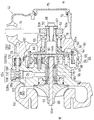
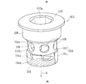
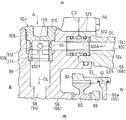
- FIG. 1 is a side view showing a motorcycle including a supercharger for an engine according to a first embodiment of the present invention. It is a horizontal sectional view showing the turbocharger. It is the perspective view which looked at the state which removed the supercharger of the same engine from back diagonally upward. It is a perspective view which shows the oil filter of the supercharger. It is a horizontal sectional view which expands and shows the supercharger.
- left side and right side refer to the left and right sides as viewed from the driver who gets on the vehicle.
- FIG. 1 is a side view of a motorcycle equipped with an engine supercharger according to a first embodiment of the present invention.
- a body frame FR of the motorcycle has a main frame 1 that forms a front half and a rear frame 2 that forms a rear half.
- a head pipe 4 is provided at the front end of the main frame 1, and a front fork 8 is pivotally supported on the head pipe 4 via a steering shaft (not shown).
- a front wheel 10 is attached to the lower end portion of the front fork 8, and a steering handle 6 is fixed to the upper end portion of the front fork 8.
- a swing arm bracket 9 is provided at the rear end of the main frame 1 which is the lower center of the vehicle body frame FR.
- a swing arm 12 is pivotally supported around a pivot shaft 16 attached to the swing arm bracket 9 so as to be swingable up and down.
- a rear wheel 14 is rotatably supported at the rear end of the swing arm 12.
- An engine E is attached to the front side of the swing arm bracket 9 at the center lower part of the body frame FR. The engine E drives the rear wheel 14 via the drive chain 11.
- the engine E includes a crankshaft 26 having a rotating shaft extending in the left-right direction (vehicle width direction), a crankcase 28 that supports the crankshaft 26, a cylinder block 30 that protrudes upward from the front upper surface of the crankcase 28, An upper cylinder head 32 and an oil pan 34 provided below the crankcase 28 are provided.
- the engine E is a four-cylinder four-cycle engine, but is not limited to this.
- crankcase 28 and the cylinder block 30 are integrally formed by molding, and the rear portion of the crankcase 28 also serves as a transmission case.
- a transmission shaft 31 and an output shaft 33 of the engine transmission are housed in the transmission case.
- a cam shaft 35 that opens and closes an intake / exhaust valve (not shown) is attached to the upper surface of the cylinder head 32. The rotation of the camshaft 35 is transmitted from the crankshaft 26 via a power transmission member (not shown) such as a chain or a belt.
- the crankcase 28, the cylinder block 30 and the cylinder head 32 constitute an engine case EC.
- a lubricant pump 29 is provided in the crankcase 28 of the engine E.
- the rotational force of the crankshaft 26 is transmitted to the rotating shaft 29 a of the lubricating liquid pump 29, and the lubricating liquid pump 29 is driven by the engine E.
- the lubricant pump 29 is connected to the lubrication target of the engine body such as the crankshaft 26 and the camshaft 35, the transmission shaft 31, and the output shaft 33 via an engine lubricant passage 95 (FIG. 3) formed in the engine case EC.
- Lubricant is supplied to the lubrication target of the transmission.
- the lubricating liquid pump 29 further supplies lubricating liquid to a supercharger 42 described later.
- exhaust pipes 36 are connected to the front surface of the cylinder head 32. These four exhaust pipes 36 are gathered below the engine E and connected to an exhaust muffler 38 disposed on the right side of the rear wheel 14.
- the fuel tank 15 is arranged on the upper part of the main frame 1, and the driver's seat 18 and the passenger seat 20 are supported on the rear frame 2.
- a resin cowling 22 is mounted on the front of the vehicle body.
- the cowling 22 covers the front of the head pipe 4.
- An air intake 24 is formed in the cowling 22.
- the air intake 24 is located at the front end of the cowling 22 and takes in intake air from the outside to the engine E.
- a transparent windshield 23 is mounted on the cowling 22.
- An intake duct 50 is disposed on the left side of the body frame FR.
- the intake duct 50 is supported by the head pipe 4 in such a manner that the front end opening 50 a faces the air intake port 24 of the cowling 22.
- the air introduced from the front end opening 50a of the intake duct 50 is pressurized by the ram effect.
- An air cleaner 40 and a supercharger 42 for purifying outside air are arranged in the vehicle width direction on the upper surface of the crankcase 28 behind the cylinder block 30.
- the intake duct 50 passes from the front of the engine E to the left outer side of the cylinder block 30 and the cylinder head 32 and guides the traveling wind A as intake air I to the air cleaner 40.
- the supercharger 42 is detachably attached to the engine E, pressurizes clean air from the air cleaner 40 and supplies the pressurized air to the engine E.
- the intake chamber 52 is disposed between the discharge port 48 of the supercharger 42 and the intake port 54 of the engine E, and the discharge port 48 of the supercharger 42 and the intake chamber 52 are directly connected.
- the intake chamber 52 stores the high-pressure intake air I supplied from the discharge port 48 of the supercharger 42.
- a throttle body 44 is disposed between the intake chamber 52 and the intake port 54.
- the intake chamber 52 is located above the supercharger 42 and the throttle body 44.
- the fuel tank 15 is disposed above the intake chamber 52 and the throttle body 44.
- the supercharger 42 is a centrifugal type, and an impeller 60 fixed to a tip end portion (left end portion) 44 a of the supercharger rotating shaft 44 and an impeller housing 63 covering the impeller 60. And a supercharger case 66 that rotatably supports the supercharger rotating shaft 44, and a speed change mechanism 64 that transmits the power of the engine E to the supercharger rotating shaft 44.
- a planetary gear transmission 64 is used as the transmission mechanism 64.
- the supercharger 42 is driven by the power of the engine E. Specifically, the rotational force of the crankshaft 26 (FIG. 1) is transmitted via the chain 74 to the input shaft 65 of the speed change mechanism 64 connected to the supercharger rotation shaft 44. More specifically, a sprocket 62 is provided at the right end of the input shaft 65, and a chain 74 is stretched around a gear 62 a of the sprocket 62.
- the supercharger case 66 includes a right input case portion 56 that houses the input shaft 65 and the sprocket 62, and a left gear case portion 58 that houses the speed change mechanism 64.
- the input case portion 56 and the gear case portion 58 are connected to each other. And bolts 59 (FIG. 5). That is, the input case portion 56 and the gear case portion 58 constitute two case halves 56 and 58 of the supercharger case 66.
- the impeller housing 63 is connected to the gear case portion 58 of the supercharger case 66 using bolts (not shown).
- the impeller housing 63 and the supercharger case 66 are, for example, molded products made of aluminum alloy.
- the input shaft 65 is a hollow shaft, and is rotatably supported by the input case portion 56 via a pair of bearings 78.
- Spline teeth 67 are formed on the outer peripheral surface of the right end portion 65 b of the input shaft 65.
- a sprocket 62 is spline-fitted to the spline teeth 67 and connected to the input shaft 65.
- a female thread portion is formed on the inner peripheral surface of the right end portion 65b of the input shaft 65, and the sprocket 62 is connected to the right end portion 65b via a washer 70 by a head of a bolt 68 screwed to the female thread portion. It is attached to.
- An opening 72 facing outward from the vehicle body is formed at the right end of the input case portion 56, and the opening 72 is closed by a cap 75.
- the right end 44b which is the base end of the supercharger rotating shaft 44, is connected to the left end 65a of the input shaft 65 via a planetary gear device (transmission mechanism) 64.
- the left end portion 65a of the input shaft 65 includes a flange-shaped flange portion 65a.
- the supercharger rotating shaft 44 is rotatably supported by the gear case portion 58 via a bearing 69.
- Two bearings 69 are arranged in the axial direction, and these two bearings 69 and 69 are accommodated in a bearing housing 76.
- External teeth 78 are formed on the right end 44 b of the supercharger rotating shaft 44.
- the planetary gear device 64 is disposed between the input shaft 65 and the supercharger rotating shaft 44 and is supported by the gear case portion 58.
- a plurality of planetary gears 80 are gear-coupled to the external teeth 78 of the right end 44b of the supercharger rotating shaft 44 side by side in the circumferential direction. That is, the external teeth 78 of the supercharger rotating shaft 44 function as the sun gear of the planetary gear unit 64.
- the planetary gear 80 is formed with a gear 81 that meshes with a sun gear (external teeth) 78. For example, three planetary gears 80 are arranged apart from each other in the circumferential direction.
- the planetary gear 80 is gear-connected to a large-diameter internal gear (ring gear) 82 on the radially outer side.
- Each planetary gear 80 is rotatably supported on the carrier shaft 86 by a bearing 84 attached to the gear case portion 58. That is, the carrier shaft 86 constitutes a support shaft for the planetary gear 80.
- needle rollers are used as the bearings 84.
- the carrier shaft 86 is fixed to a disk-shaped fixing member 88, and the fixing member 88 is fixed to the gear case portion 58 with bolts 90. That is, the carrier shaft 86 is fixed and the planetary gear 80 does not revolve.
- An input gear 92 provided at the left end portion of the input shaft 65 is gear-connected to the internal gear 82.
- the input gear 92 is an external gear having external teeth formed on the outer periphery of the disc.
- the input gear 92 and the internal gear 82 are relatively movable in the radial direction within a range in which the meshing can be maintained.
- the internal gear 82 is gear-connected so as to rotate integrally with the input shaft 65 in the same rotational direction, the carrier shaft 86 is fixed, and the planetary gear 80 rotates in the same rotational direction as the internal gear 82.
- the sun gear (external gear 78) is formed on the supercharger rotating shaft 44 serving as an output shaft, and rotates in the direction opposite to the planetary gear 80.
- the internal gear 82 and the input gear 92 of the input shaft 65 are connected via a positioning member 93 in a state where movement of the input shaft 65 in the axial direction is restricted.
- the positioning member 93 is formed of an annular ring member and is disposed on both sides of the input gear 92 in the axial direction.
- the positioning member 93 of this embodiment is formed by bending a steel wire in an annular shape.
- the supercharger lubricating liquid passage 94 is formed simultaneously with the supercharger case 66 by molding. In this embodiment, oil is used as the lubricating liquid OL.
- an oil layer 96 is formed between the supercharger case 66 and the bearing housing 76, and a supercharger lubricating fluid passage 94 is connected to the oil layer 96.
- the oil layer 96 has a function of relaxing the swing of the supercharger rotating shaft 44.
- a part of the lubricating liquid OL of the oil layer 96 is supplied to the bearing 69 which is a lubricated part.
- the oil that has passed through the right bearing 69 is supplied to the external teeth 78 and lubricates the meshed portions of the external teeth 78 and the gears 81.
- the supercharger lubricating fluid passage 94 is circular in cross section, and has a first passage 98 extending in the radial direction from the bearing housing 76 and a second passage extending in the axial direction and connected to the radially outer end of the first passage 98. And a passage 100.
- the radially outer end of the first passage 98 is open, and a female screw 98a is formed at the open end.
- the second passage 100 extends over the input case portion 56 and the gear case portion 58 which are two case halves.
- the supercharger lubricant passage 94 is connected to an engine lubricant passage 95 formed inside the engine E in FIG. That is, an outlet 95a of the engine lubricating fluid passage 95 for introducing the lubricating fluid OL from the lubricating fluid pump 29 (FIG. 1) into the supercharger 42 is formed on the mating surface 102 of the crankcase 28 with the supercharger case 66. ing.
- the engine lubricating fluid passage 95 has an outlet 95 a directly connected to the second passage 100 of the supercharger lubricating fluid passage 94 of the supercharger case 66, and the lubricating fluid OL is supplied from the outlet 95 a to the bearing 69. Supply.
- the lubricating liquid OL is supplied from the lubricating liquid pump 29 (FIG. 1) to the supercharger lubricating liquid passage 94.
- the lubricant OL supplied to the supercharger lubricant passage 94 is also supplied to the transmission mechanism 64, the sprocket 62, the chain 74, and the like through a passage (not shown).
- an oil filter 104 for removing foreign matter of the lubricating fluid OL is installed in the supercharger lubricating fluid passage 94.
- the oil filter 104 is disposed on the upstream side of the lubricated portion of the supercharger 42, and filters the oil before being supplied to the lubricated portion.
- the oil filter 104 is detachably attached to the supercharger case 66 by an operation from the outside of the supercharger 42. Specifically, the oil filter 104 is detachable in the radial direction with respect to the supercharger case 66. Thereby, the oil filter 104 does not interfere with the impeller housing 63 and the speed change mechanism 64 at the time of attachment / detachment.
- the oil filter 104 is exposed to the outside of the supercharger case 66, the filter part 106 that removes foreign matter from the lubricating liquid OL, the gear case part 58, that is, the attachment part 108 that is fixed to the supercharger case 66. And an operation unit 110 to which a detachable tool is engaged.
- the mounting portion 108 is formed with a male screw 108 a that is screwed into the female screw 98 a of the supercharger case 66, and the oil filter 104 is attached to a radially outer end portion that forms the open end of the first passage 98. Yes. That is, the mounting portion 108 screwed to the supercharger case 66 also serves as a sealing portion for sealing the supercharger lubricating fluid passage 94.
- the first passage 98 extends in a fastening direction that is radially inward of the mounting portion 108
- the second passage 100 extends in a direction orthogonal to the fastening direction
- the filter portion 106 is connected to the first passage 98, the second passage 100, and the like. It is arranged at the connection part.
- the filter portion 106 of the oil filter 104 includes a metal upstream portion 112 formed integrally with the mounting portion 108, and an elastic body such as rubber that is separate from the upstream portion 112.
- the downstream part 114 which consists of these.
- the attachment portion 108, the operation portion 110, and the upstream portion 112 are inseparably integrated and made of, for example, a steel material such as stainless steel.
- the attachment portion 108, the operation portion 110, and the upstream portion 112 may be separated. In that case, the upstream portion 112 and the downstream portion 114 may be integrally formed of an elastic body.
- the upstream portion 112 of the filter portion 106 has a cylindrical shape having an axial center in the fastening direction A of the mounting portion 108, and a plurality of through holes 118 are formed on the outer peripheral wall thereof.
- the outer opening 112a of the upstream portion 112 is pressed and closed against the bottom wall of the mounting portion 108, and the downstream portion 114 is pressed to the inner opening 112b.
- the downstream portion 114 also has a cylindrical shape having an axis in the fastening direction A, the outer opening 114a communicates with the inner opening 112b of the upstream portion 112, and the mesh 120 is provided in the vicinity of the inner opening 114b.
- the outer peripheral portion of the mesh 120 is embedded in the downstream portion 114.
- the inner end surface of the downstream portion 114 abuts on an annular support step portion 99 formed on the inner surface of the first passage 98, and positioning in the fastening direction A is performed.
- a primary oil filter (not shown) is arranged inside the oil pan 34 of the engine E of FIG. 1, and a secondary oil filter (not shown) is arranged in the engine lubricating fluid passage 95, and the oil filter of FIG.
- Reference numeral 104 denotes a tertiary oil filter.
- the oil filter 104 is set to be coarser than the secondary oil filter.
- the passage area of the first passage 98 on the downstream side of the oil filter 104 is set larger than the passage area of the second passage 100 on the upstream side of the oil filter 104. As a result, the flow rate of the oil OL is reduced on the upstream side of the oil filter 104, so that foreign matters are easily removed.
- the portion to which the oil filter 104 is attached in the supercharger case 66 bulges outward in the radial direction as compared with other portions. Thereby, the oil filter 104 is arrange
- the supercharger case 66 is provided with a flow rate adjusting member 122 that constitutes a part of the supercharger lubricating fluid passage 94.
- the flow rate adjusting member 122 is a cylindrical member, and is disposed in a recess 124 provided in a connection portion between the input case portion 56 and the gear case portion 58.
- the recess 124 is formed by enlarging a part of the second passage 100 of the supercharger lubricant passage 94 and forms a storage space concentric with the supercharger lubricant passage 94.
- a hollow hole in a cylindrical shape constitutes a part of the supercharger lubricating fluid passage 94.
- An O-ring 125 made of an elastic material such as rubber is attached to the outer peripheral surface of the flow rate adjusting member 122.
- the space between the flow rate adjusting member 122 and the recess 124 is sealed by the O-ring 125, so that the space between the connection surface CS between the input case portion 56 and the gear case portion 58 and the supercharger lubricant passage 94 is sealed. Yes.
- the flow rate adjusting member 122 is detachable by loosening the bolt 59 and separating the input case portion 56 and the gear case portion 58.
- the flow rate adjusting member 122 selects and equips a plurality of cylinders having different inner diameters, thereby adjusting the amount of the lubricating liquid OL flowing through the supercharger lubricating liquid passage 94.
- the flow rate adjusting member 122A shown by the two-dot chain line is arranged, so that the passage area of the supercharger lubricating fluid passage 94 is reduced, and the lubricating liquid OL The flow rate can be suppressed.
- the lubricant pump 29 and the supercharger 42 are driven in conjunction with the crankshaft 26.
- a part of the lubricating liquid pumped from the lubricating liquid pump 29 is introduced into the second passage 100 of the supercharger lubricating fluid passage 94 from the outlet 95a of the engine lubricating fluid passage 95 in FIG.
- the lubricating liquid OL introduced into the second passage 100 passes through the oil filter 104 after the flow rate is adjusted by the flow rate adjusting member 122.
- the lubricating liquid OL is introduced into the oil filter 104 from the through hole 118 of the upstream portion 112 of the filter portion 106 in the oil filter 104 shown in FIG. The direction is changed. Further, the lubricating liquid OL passes through the mesh 120 of the downstream portion 114 of the filter unit 106 to remove foreign matter, and is then guided to the first passage 98 of the supercharger lubricating fluid passage 94. The lubricating liquid OL guided to the first passage 98 is supplied to the bearing housing 76 in FIG. 2 and lubricates the bearing 69.
- a tool such as a torque wrench is engaged with the engagement hole 110a such as the hexagonal hole of the operation part 110 of the oil filter 104, and the attachment part 108 is rotated and loosened.
- the attachment portion 108 integrated with the upstream portion 112 and the downstream portion 114 are removed from the turbocharger case 66 in this order. After the removed mesh 120 of the downstream portion 114 is cleaned, the downstream portion 114 is again inserted into the supercharger lubricating fluid passage 94 or a new downstream portion 114 is inserted.
- the oil filter 104 is supercharged by inserting the attachment portion 108 into the supercharger lubricating fluid passage 94, further engaging the tool with the engagement hole 110 a of the operation portion 110, and tightening the attachment portion 108. Attach to machine case 66.
- the supercharger 42 of the present embodiment is a centrifugal supercharger, the performance is proportional to the rotational speed, and the rotational speed of the supercharger rotating shaft 44 is set high. For this reason, there is a high demand for removing foreign matter from the oil OL supplied to the bearing 69. Furthermore, since a part of the supercharger rotating shaft 44 is supported by the oil layer 96, there is a high demand for removing foreign matter from the oil OL supplied to the oil layer 96.
- the oil filter 104 is detachably attached to the supercharger case 66 by an operation from the outside of the supercharger 42. Therefore, even when the supercharger lubricant passage 94 is formed inside the supercharger case 66, the oil filter 104 can be easily replaced or cleaned.
- the supercharger lubricating fluid passage 94 is connected to the engine lubricating fluid passage 95, and foreign matter such as metal wear powder may be mixed in the lubricating fluid OL in the engine lubricating fluid passage 95. Since it is provided, such foreign matter can be removed. Therefore, the oil of the engine E can be suitably used for lubricating the supercharger 42.
- the oil filter 104 has a filter part 106 that removes foreign matter, an attachment part 108 that is screwed into the supercharger case 66, and an operation part that is exposed to the outside of the supercharger case 66. Therefore, the oil filter 104 can be easily replaced by operating the operation unit 110 using a tool from the outside of the supercharger 42. Further, since the attachment portion 108 also serves as a sealing portion that seals the supercharger lubricating fluid passage 94, the number of parts can be reduced.
- the filter part 106 of the oil filter 104 is arranged at the connection part between the first passage 98 and the second passage 100. Thereby, the oil filter 104 can be formed using the plug hole at the time of processing.
- the oil filter 104 is attached to a first passage 98 extending in the radial direction from the bearing housing 76. Thereby, since the oil filter 104 can be disposed in the vicinity of the bearing 69 that is the lubricated portion, it is possible to effectively prevent foreign matter from entering the bearing 69.
- the supercharger case 66 is provided with a flow rate adjusting member 122 that constitutes a part of the supercharger lubricating fluid passage 94.
- the amount of the supplied lubricating liquid may be larger than the amount of the lubricating liquid required for the supercharger 42, but the flow rate adjusting member 122 is selected. Can adjust the flow rate of the lubricating liquid OL.
- the flow rate adjusting member 122 is detachable by loosening the bolt 59 (FIG. 5) and separating the input case portion 56 and the gear case portion 58, and therefore can be easily replaced.
- the internal gear 82 of the planetary gear device 64 and the input gear 92 of the input shaft 65 are connected via a positioning member 93 in a state where movement of the input shaft 65 in the axial direction is restricted.
- the positioning member 93 has a simple structure because the wire is bent into a ring shape.
- the present invention is not limited to the above embodiment, and various additions, changes, or deletions are possible without departing from the gist of the present invention.
- the present invention is applied to an engine of a motorcycle has been described.
- the supercharger of the present invention can be applied to engines other than motorcycles, such as ships, ships, and the like. It can also be applied to.
- an edge belt may be used instead of the chain 74.
- the filter part 106 and the attachment part 108 may be integrally formed.
- the first passage 98 and the second passage 100 are orthogonal to each other.
- both the passages 98 and 100 need only intersect with each other, and are not necessarily orthogonal to each other.
- the supercharger case 66 may not have a bearing. Therefore, such a thing is also included in the scope of the present invention.
Landscapes
- Engineering & Computer Science (AREA)
- Mechanical Engineering (AREA)
- General Engineering & Computer Science (AREA)
- Chemical & Material Sciences (AREA)
- Combustion & Propulsion (AREA)
- Supercharger (AREA)
- Lubrication Of Internal Combustion Engines (AREA)
- General Details Of Gearings (AREA)
Abstract
Le compresseur d'alimentation selon l'invention (42) comprend: un impulseur (60) qui pressurise l'air d'admission du moteur (E); un arbre tournant de compresseur d'alimentation (44) auquel l'impulseur (60) est fixé; et un carter de compresseur d'alimentation (66) qui supporte l'arbre tournant de compresseur d'alimentation (44) de manière rotative. Un trajet de lubrifiant de compresseur d'alimentation (94) qui mène un lubrifiant (OL) à un logement de roulement (76) est formé à l'intérieur du carter de compresseur d'alimentation et un filtre à huile (104) qui retire les contaminants dans le lubrifiant (OL) est disposé dans le trajet de lubrifiant de compresseur d'alimentation (94). Le filtre à huile (104) est fixé au carter de compresseur d'alimentation (66) de manière à pouvoir être fixé/détaché au moyen d'une opération extérieure au compresseur d'alimentation (42).
Priority Applications (3)
| Application Number | Priority Date | Filing Date | Title |
|---|---|---|---|
| EP14861748.3A EP3073093B1 (fr) | 2013-11-18 | 2014-11-17 | Compresseur d'alimentation de moteur |
| CN201480061655.8A CN105723069B (zh) | 2013-11-18 | 2014-11-17 | 发动机的增压器 |
| US15/087,931 US10012140B2 (en) | 2013-11-18 | 2016-03-31 | Engine supercharger |
Applications Claiming Priority (6)
| Application Number | Priority Date | Filing Date | Title |
|---|---|---|---|
| PCT/JP2013/081037 WO2015072033A1 (fr) | 2013-11-18 | 2013-11-18 | Dispositif de transmission de puissance motrice pour compresseur de suralimentation |
| JPPCT/JP2013/081037 | 2013-11-18 | ||
| JPPCT/JP2013/081039 | 2013-11-18 | ||
| PCT/JP2013/081039 WO2015072035A1 (fr) | 2013-11-18 | 2013-11-18 | Compresseur d'alimentation pour moteur |
| JP2014222865A JP6437788B2 (ja) | 2013-11-18 | 2014-10-31 | エンジンの過給機 |
| JP2014-222865 | 2014-10-31 |
Related Child Applications (1)
| Application Number | Title | Priority Date | Filing Date |
|---|---|---|---|
| US15/087,931 Continuation US10012140B2 (en) | 2013-11-18 | 2016-03-31 | Engine supercharger |
Publications (1)
| Publication Number | Publication Date |
|---|---|
| WO2015072561A1 true WO2015072561A1 (fr) | 2015-05-21 |
Family
ID=53057495
Family Applications (1)
| Application Number | Title | Priority Date | Filing Date |
|---|---|---|---|
| PCT/JP2014/080311 WO2015072561A1 (fr) | 2013-11-18 | 2014-11-17 | Compresseur d'alimentation de moteur |
Country Status (5)
| Country | Link |
|---|---|
| US (1) | US10012140B2 (fr) |
| EP (1) | EP3073093B1 (fr) |
| JP (1) | JP6437788B2 (fr) |
| CN (1) | CN105723069B (fr) |
| WO (1) | WO2015072561A1 (fr) |
Cited By (1)
| Publication number | Priority date | Publication date | Assignee | Title |
|---|---|---|---|---|
| WO2019043893A1 (fr) * | 2017-08-31 | 2019-03-07 | 三菱重工エンジン&ターボチャージャ株式会社 | Dispositif d'élimination de corps étrangers, et turbocompresseur équipé d'un dispositif d'élimination de corps étrangers |
Citations (8)
| Publication number | Priority date | Publication date | Assignee | Title |
|---|---|---|---|---|
| JPS4417880Y1 (fr) * | 1965-02-08 | 1969-08-02 | ||
| JPS60124514U (ja) * | 1984-01-30 | 1985-08-22 | スズキ株式会社 | エンジンの潤滑オイル絞り弁 |
| JPH06212989A (ja) * | 1993-01-14 | 1994-08-02 | Hitachi Ltd | 過給機 |
| JP2000034931A (ja) * | 1998-07-17 | 2000-02-02 | Ishikawajima Harima Heavy Ind Co Ltd | ターボチャージャの給油装置 |
| US7040874B1 (en) * | 2004-11-18 | 2006-05-09 | Honeywell International, Inc. | Integrated turbocharger lubricant filter system |
| JP2007023901A (ja) * | 2005-07-15 | 2007-02-01 | Mazda Motor Corp | エンジンのバランサ装置 |
| WO2011046098A1 (fr) | 2009-10-14 | 2011-04-21 | 川崎重工業株式会社 | Dispositif de compresseur volumétrique de moteur |
| JP2013224676A (ja) * | 2009-10-14 | 2013-10-31 | Kawasaki Heavy Ind Ltd | エンジンの過給機駆動装置 |
Family Cites Families (17)
| Publication number | Priority date | Publication date | Assignee | Title |
|---|---|---|---|---|
| US4900343A (en) * | 1980-10-25 | 1990-02-13 | Yamaha Hatsudoki Kabushiki Kaisha | Induction system for internal combustion engines |
| JPS589033U (ja) | 1981-07-08 | 1983-01-20 | 住友電気工業株式会社 | ガス絶縁ケ−ブル接続部 |
| JPS5890330U (ja) * | 1981-12-15 | 1983-06-18 | スズキ株式会社 | 排気過給装置用潤滑装置 |
| JPH0270920A (ja) * | 1988-09-02 | 1990-03-09 | Yamaha Motor Co Ltd | 過給機付きエンジンを備えた自動二輪車 |
| JP2716763B2 (ja) * | 1988-12-14 | 1998-02-18 | ヤマハ発動機株式会社 | 自動二輪車用エンジンのバランサ軸配置構造 |
| JPH0632897U (ja) * | 1992-10-06 | 1994-04-28 | 栃木富士産業株式会社 | 潤滑オイル供給装置 |
| JPH08121186A (ja) * | 1994-10-24 | 1996-05-14 | Tochigi Fuji Ind Co Ltd | 機械式過給機 |
| US6502398B2 (en) * | 2001-01-16 | 2003-01-07 | Davorin D. Kapich | Exhaust power recovery system |
| JP2004190491A (ja) * | 2002-12-06 | 2004-07-08 | Hitachi Unisia Automotive Ltd | 燃料供給装置 |
| US7516727B2 (en) * | 2006-09-21 | 2009-04-14 | Kawasaki Jukogyo Kabushiki Kaisha | Vehicle combustion engine |
| US7765805B2 (en) * | 2007-07-24 | 2010-08-03 | Kasi Forvaltning I Goteborg Ab | Enhanced supercharging system and an internal combustion engine having such a system |
| DE102007062223A1 (de) * | 2007-12-21 | 2009-06-25 | Bosch Mahle Turbo Systems Gmbh & Co. Kg | Ladeeinrichtung |
| EP2241735A4 (fr) * | 2008-01-28 | 2017-08-02 | IHI Corporation | Compresseur volumétrique |
| US8234867B2 (en) * | 2008-06-25 | 2012-08-07 | Ford Global Technologies, Llc | Turbocharger system for internal combustion engine with internal isolated turbocharger oil drainback passage |
| US8534424B2 (en) * | 2008-09-10 | 2013-09-17 | Ford Global Technologies, Llc | Automotive turbocharger with integral lubricating oil filter |
| JP2010138747A (ja) * | 2008-12-10 | 2010-06-24 | Honda Motor Co Ltd | V型内燃機関 |
| IN2014DN07369A (fr) * | 2012-02-17 | 2015-04-24 | Borgwarner Inc |
-
2014
- 2014-10-31 JP JP2014222865A patent/JP6437788B2/ja active Active
- 2014-11-17 EP EP14861748.3A patent/EP3073093B1/fr active Active
- 2014-11-17 CN CN201480061655.8A patent/CN105723069B/zh active Active
- 2014-11-17 WO PCT/JP2014/080311 patent/WO2015072561A1/fr active Application Filing
-
2016
- 2016-03-31 US US15/087,931 patent/US10012140B2/en active Active
Patent Citations (8)
| Publication number | Priority date | Publication date | Assignee | Title |
|---|---|---|---|---|
| JPS4417880Y1 (fr) * | 1965-02-08 | 1969-08-02 | ||
| JPS60124514U (ja) * | 1984-01-30 | 1985-08-22 | スズキ株式会社 | エンジンの潤滑オイル絞り弁 |
| JPH06212989A (ja) * | 1993-01-14 | 1994-08-02 | Hitachi Ltd | 過給機 |
| JP2000034931A (ja) * | 1998-07-17 | 2000-02-02 | Ishikawajima Harima Heavy Ind Co Ltd | ターボチャージャの給油装置 |
| US7040874B1 (en) * | 2004-11-18 | 2006-05-09 | Honeywell International, Inc. | Integrated turbocharger lubricant filter system |
| JP2007023901A (ja) * | 2005-07-15 | 2007-02-01 | Mazda Motor Corp | エンジンのバランサ装置 |
| WO2011046098A1 (fr) | 2009-10-14 | 2011-04-21 | 川崎重工業株式会社 | Dispositif de compresseur volumétrique de moteur |
| JP2013224676A (ja) * | 2009-10-14 | 2013-10-31 | Kawasaki Heavy Ind Ltd | エンジンの過給機駆動装置 |
Cited By (3)
| Publication number | Priority date | Publication date | Assignee | Title |
|---|---|---|---|---|
| WO2019043893A1 (fr) * | 2017-08-31 | 2019-03-07 | 三菱重工エンジン&ターボチャージャ株式会社 | Dispositif d'élimination de corps étrangers, et turbocompresseur équipé d'un dispositif d'élimination de corps étrangers |
| JPWO2019043893A1 (ja) * | 2017-08-31 | 2020-09-24 | 三菱重工エンジン&ターボチャージャ株式会社 | 異物除去装置及びこの異物除去装置を備えるターボチャージャ |
| US11415050B2 (en) | 2017-08-31 | 2022-08-16 | Mitsubishi Heavy Industries Engine & Turbocharger, Ltd. | Contamination removing device and turbocharger including contamination removing device |
Also Published As
| Publication number | Publication date |
|---|---|
| US10012140B2 (en) | 2018-07-03 |
| JP2015098867A (ja) | 2015-05-28 |
| EP3073093A1 (fr) | 2016-09-28 |
| JP6437788B2 (ja) | 2018-12-12 |
| EP3073093A4 (fr) | 2017-07-26 |
| CN105723069A (zh) | 2016-06-29 |
| EP3073093B1 (fr) | 2019-08-28 |
| US20160215688A1 (en) | 2016-07-28 |
| CN105723069B (zh) | 2019-02-15 |
Similar Documents
| Publication | Publication Date | Title |
|---|---|---|
| JP5945325B2 (ja) | エンジンの過給機 | |
| JP5956055B2 (ja) | 車両用エンジンの潤滑システム | |
| EP2873831B1 (fr) | Moteur ayant un compresseur d'alimentation | |
| EP2899383A1 (fr) | Moteur équipé d'un compresseur | |
| US10012306B2 (en) | Lubricating structure for power transmitting system | |
| WO2014041946A1 (fr) | Moteur doté d'un compresseur | |
| JP6437788B2 (ja) | エンジンの過給機 | |
| US20170268527A1 (en) | Impeller for supercharger | |
| JP6433279B2 (ja) | 過給機のインペラ | |
| JP5650608B2 (ja) | 小型車両用内燃機関のキック始動装置 | |
| JP6392655B2 (ja) | 過給機のインペラ | |
| WO2014041945A1 (fr) | Moteur doté d'un compresseur | |
| JP6204489B2 (ja) | エンジンの過給機 |
Legal Events
| Date | Code | Title | Description |
|---|---|---|---|
| 121 | Ep: the epo has been informed by wipo that ep was designated in this application |
Ref document number: 14861748 Country of ref document: EP Kind code of ref document: A1 |
|
| REEP | Request for entry into the european phase |
Ref document number: 2014861748 Country of ref document: EP |
|
| WWE | Wipo information: entry into national phase |
Ref document number: 2014861748 Country of ref document: EP |
|
| NENP | Non-entry into the national phase |
Ref country code: DE |