WO2015068307A1 - パーツフィーダー - Google Patents
パーツフィーダー Download PDFInfo
- Publication number
- WO2015068307A1 WO2015068307A1 PCT/JP2013/080445 JP2013080445W WO2015068307A1 WO 2015068307 A1 WO2015068307 A1 WO 2015068307A1 JP 2013080445 W JP2013080445 W JP 2013080445W WO 2015068307 A1 WO2015068307 A1 WO 2015068307A1
- Authority
- WO
- WIPO (PCT)
- Prior art keywords
- component
- air injection
- guide plate
- conveyance path
- air
- Prior art date
- Legal status (The legal status is an assumption and is not a legal conclusion. Google has not performed a legal analysis and makes no representation as to the accuracy of the status listed.)
- Ceased
Links
Images





Classifications
-
- B—PERFORMING OPERATIONS; TRANSPORTING
- B65—CONVEYING; PACKING; STORING; HANDLING THIN OR FILAMENTARY MATERIAL
- B65G—TRANSPORT OR STORAGE DEVICES, e.g. CONVEYORS FOR LOADING OR TIPPING, SHOP CONVEYOR SYSTEMS OR PNEUMATIC TUBE CONVEYORS
- B65G47/00—Article or material-handling devices associated with conveyors; Methods employing such devices
- B65G47/02—Devices for feeding articles or materials to conveyors
- B65G47/04—Devices for feeding articles or materials to conveyors for feeding articles
- B65G47/12—Devices for feeding articles or materials to conveyors for feeding articles from disorderly-arranged article piles or from loose assemblages of articles
- B65G47/14—Devices for feeding articles or materials to conveyors for feeding articles from disorderly-arranged article piles or from loose assemblages of articles arranging or orientating the articles by mechanical or pneumatic means during feeding
- B65G47/1407—Devices for feeding articles or materials to conveyors for feeding articles from disorderly-arranged article piles or from loose assemblages of articles arranging or orientating the articles by mechanical or pneumatic means during feeding the articles being fed from a container, e.g. a bowl
- B65G47/1442—Devices for feeding articles or materials to conveyors for feeding articles from disorderly-arranged article piles or from loose assemblages of articles arranging or orientating the articles by mechanical or pneumatic means during feeding the articles being fed from a container, e.g. a bowl by means of movement of the bottom or a part of the wall of the container
- B65G47/1457—Rotating movement in the plane of the rotating part
Definitions
- the present invention relates to a parts feeder, and more particularly to a parts feeder that supplies a slider of a slide fastener to a slider assembling apparatus.
- a conventional parts feeder it is provided with a parts conveyance path for conveying parts in a predetermined posture, and an upstream clogging release part and a downstream clogging release part provided on the parts conveyance path, and the upstream clogging release part is a cylinder It is equipped with a hook that drops and discharges the jammed part (slider) from the parts conveyance path, and the downstream clogging release part moves up by the cylinder and drops the jammed part from the parts conveyance path and discharges it.
- a device including a hook that performs a detection and a component detection device that detects a conveyance state of a component that passes through a downstream clogging release unit for example, see Patent Document 1).
- the present invention has been made in view of the above-described circumstances, and an object of the present invention is to provide a parts feeder that can reliably discharge clogged parts from the parts conveyance path.
- the parts feeder according to (1) wherein the discharge device is provided upstream of the detection device.
- the air injection device is a first air injection device, which is provided upstream of the component conveyance path discharge device, injects air to the components on the component conveyance path, and discharges the components to the component storage unit.
- the part feeder according to (1) or (2) further comprising a second air injection device.
- the parts that could not be discharged by the discharge device by the air injection of the first air injection device are discharged to the component housing portion, and the components are disposed downstream of the second air injection device by the air injection of the second air injection device.
- the parts feeder according to (3) wherein the parts are discharged to the parts accommodating portion so that the parts are not transferred.
- the component is a fuselage that constitutes a slide fastener slider, and connects the upper wing plate and the lower wing plate that are spaced apart in the vertical direction and arranged in parallel, and the upper wing plate and the lower wing plate at the front end portion.
- a guide column, and a front column and a rear column provided on the upper surface of the upper blade, and the component conveying path includes an inclined surface of a base unit attached to the component housing unit, and a movable block mounted on the base unit
- a third guide plate inserted between the front and rear pillars of the component, and the discharge device is attached to the component accommodating portion and drives the movable block up and down,
- a third guide plate attached to the inclined surface of the base And a second drive device that is driven up and down.
- the movable block is moved up by the first drive device, and the third guide plate is moved up by the second drive device, thereby widening the component conveyance path.
- the parts feeder according to any one of (1) to (4), wherein (6)
- the detection device includes a light projecting element and a light receiving element, and the detection light of the light projecting element is irradiated onto the component conveyance path and received by the light receiving element.
- the light projecting element and the light receiving element are The part feeder according to any one of (1) to (5), wherein it is detected whether or not a part has been transported to detect clogging of parts in the part transport path.
- a component accommodating portion that accommodates components, a component conveying path that conveys the components in the component accommodating portion in a predetermined posture, and the component conveying path are provided.
- the air injection device that is provided and injects air to the component and discharges the component to the component accommodating portion is provided, so that the clogged component can be reliably discharged from the component conveyance path.
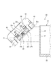
- FIG. 3 is a sectional view taken along line AA in FIG. 2.
- FIG. 3 is a sectional view taken along line BB in FIG.
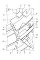
- FIG. 6 is a cross-sectional view illustrating a state in which the movable block and the third guide plate illustrated in FIG. 5 are moved upward and the component conveyance path is expanded.
- FIG. 7 is a perspective view for explaining a state in which components are blown away by the first air injection device shown in FIG. 2 in the state of FIG. 6.
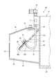
- FIG. 3 is a cross-sectional view taken along the line CC of FIG. It is sectional drawing explaining the state by which components are blown away by the 2nd air injection apparatus shown in FIG.
- the parts feeder 10 of the present embodiment is provided with a base 11 placed on a floor surface and a substantially circular shape provided on the base 11 and vibrated by a vibration generator (not shown).
- a parts feeder main body 20 is provided.
- the parts feeder main body 20 is a spiral component that arranges and conveys a component accommodating portion 21 that accommodates a component P ⁇ b> 1 thrown from above and a component P ⁇ b> 1 in the component accommodating portion 21 in a predetermined posture.
- a detection device 40 provided on the conveyance path 30 and the component conveyance path 30 to detect clogging of the component P1 according to the conveyance state of the component P1, and provided on the upstream side of the detection device 40 of the component conveyance path 30.
- the parts conveying path 30 is widened, and a discharging device 50 that discharges the parts P1 to the parts container 21 and a downstream side of the discharging device 50 of the parts conveying path 30 are provided, and air is injected into the parts P1
- the first air injection device 60 that discharges the component P1 to the component housing portion 21 and the upstream of the discharge device 50 of the component conveyance path 30 are provided, and air is injected to the component P1 on the component conveyance path 30 do it, Comprising a second air injector 70 to discharge the goods P1 in component housing 21.
- the component P1 is conveyed on the component conveyance path 30 by vibration of a vibration generator (not shown), and in this embodiment, the component accommodating portion 21 ⁇ second air injection device 70 ⁇ discharge device 50 ⁇ first air injection device. 60 ⁇ Detection device 40 is conveyed in this order. Further, the clogging of the part P1 means a state in which the conveyance of the part P1 is stopped for some reason in the part conveyance path 30.
- This component P1 is a fuselage that constitutes a slide fastener slider, and includes an upper wing plate Pa and a lower wing plate Pb that are spaced apart in the vertical direction and arranged in parallel, and an upper wing plate Pa and a lower wing plate Pb at the front end portion.
- a front pillar Pe and a rear pillar Pf provided on the upper surface of the upper wing plate Pa, a guide pillar Pc to be connected to the upper wing plate Pa, and a flange Pd provided along the left and right side edges of the upper wing plate Pa.
- the body to be conveyed is the body, but the present invention is not limited to this.
- it may be a cover member, a claw member, a spring member, a handle, or the like that constitutes a slide fastener slider.
- the component housing portion 21 includes a substantially disc-shaped bottom plate 22 and a substantially cylindrical side plate 23 attached to the periphery of the bottom plate 22.
- the component P ⁇ b> 1 discharged by the discharge device 50, the first air injection device 60, and the second air injection device 70 is placed on the outer peripheral surface of the side plate 23 in the component storage portion 21.
- a component return passage 25 for returning to is attached.
- the component return passage 25 includes a return bottom plate 26 attached to the side plate 23 so as to be inclined downward, and a return side plate 27 attached to the outer edge of the return bottom plate 26.
- the component conveyance path 30 in the detection device 40 includes a substantially trapezoidal first base portion 31 attached to the outer peripheral surface of the side plate 23 of the component accommodating portion 21, and the first base portion 31.
- a lower guide plate 32a that is attached to the inclined surface 31a and guides the lower surface of the lower blade plate Pb of the component P1, a pair of spacers 32b that are attached to both ends in the width direction of the upper surface of the lower guide plate 32a, and a pair of spacers 32b
- an upper guide plate 32c that guides the side surfaces of the front and rear pillars Pe and Pf of the component P1.
- the inclined surface 31 a of the first base portion 31 is a surface inclined downward toward the side away from the side plate 23. Accordingly, the lower guide plate 32a, the pair of spacers 32b, and the pair of upper guide plates 32c are inclined in the same manner as the inclined surface 31a.
- the detection device 40 is attached to the upper surface of the pair of upper guide plates 32 c and is provided with a support member 41 having an L-shaped cross section provided so as to be bridged between the pair of upper guide plates 32 c.
- a substantially U-shaped support stay 42 attached to the support member 41, and a light projecting element 43 and a light receiving element 44 attached to both ends of the support stay 42.
- the detection light R of the light projecting element 43 is irradiated between the lower guide plate 32 a and the pair of upper guide plates 32 c and received by the light receiving element 44.
- the light projecting element 43 and the light receiving element 44 detect whether or not the part P1 has been transported per predetermined time, and detect clogging of the part P1 in the part transport path 30.
- the light projecting element 43 and the light receiving element 44 are photoelectric sensors, and the detection light R irradiated from the light projecting element 43 to the light receiving element 44 is blocked by the part P1 that is a detection target, so that the part P1 is removed. It is possible to detect or detect the component P1 when the detection light R irradiated from the light projecting element 43 to the light receiving element 44 is reflected by the component P1 that is a detection target.
- the component conveyance path 30 in the discharging device 50 includes an inclined surface 33 a of a substantially trapezoidal second base portion 33 attached to the outer peripheral surface of the side plate 23 of the component accommodating portion 21, and a second one.
- the guide plate 35a is attached to the inclined surface 34a of the movable block 34, and is attached to the second guide plate 35b that guides the front end face of the lower blade plate Pb of the component P1, and the second drive device 52 described later, and the component P1 And a third guide plate 35c inserted between the front and rear pillars Pe and Pf.
- the inclined surface 33 a of the second base portion 33 and the inclined surface 34 a of the movable block 34 are surfaces inclined downward toward the side away from the side plate 23.
- the inclined surface 33a of the second base portion 33 guides the lower surface of the rear end portion of the lower blade Pb of the component P1, and the inclined surface 34a of the movable block 34 is provided at the front end portion of the lower blade Pb of the component P1. Guide the lower surface.
- a drop slit 35d is formed.
- the second base portion 33 is formed with a through hole 33b through which the dropped component P1 is dropped into the component return passage 25.
- the discharge device 50 is attached to the outer peripheral surface of the side plate 23 of the component housing portion 21, and includes a first drive device 51 that drives the movable block 34 up and down, and a second base portion 33.
- a second driving device 52 that is attached to the inclined surface 33a and drives the third guide plate 35c up and down.
- the first driving device 51 includes a cylinder 51a that is fixed to the outer peripheral surface of the side plate 23 of the component housing portion 21, and a substantially L-shaped support stay 51c that is fixed to the slider 51b of the cylinder 51a.
- a movable block 34 is fixed to the lower end portion of the first frame.
- the second driving device 52 includes a base plate 53 fixed so as to be orthogonal to the inclined surface 33a of the second base portion 33, a cylinder 52a fixed to the inner surface of the base plate 53, and a slider 52b of the cylinder 52a. And a third staying plate 52c fixed to the lower end of the supporting stay 52c.
- the third guide plate 35 c is driven up and down in a direction orthogonal to the inclined surface 33 a of the second base portion 33.
- the movable block 34 is moved upward by the first drive device 51 as shown in FIG.
- the second guide device 35 moves the third guide plate 35c upward, and the inclined surface 33a of the second base portion 33, the inclined surface 34a of the movable block 34, the first guide plate 35a, the second guide plate 35b, and the third guide.
- the component conveyance path 30 constituted by the plate 35c is expanded. For this reason, the component P1 in the corresponding place is dropped into the component return passage 25 through the component drop slit 35d and the through hole 33b of the second base portion 33, which are also widened, regardless of the presence or absence of clogging. Returned to the unit 21. Note that the conveyance of the component P1 due to vibration is not stopped even during the upward movement of the movable block 34 and the third guide plate 35c.
- the first air injection device 60 injects air onto the component P1 in the vicinity of the downstream end of the third guide plate 35c of the discharge device 50, and drops the component P1 that could not be dropped by the discharge device 50. 2 and 7, a nozzle base 61 fixed to the outer surface of the return side plate 27, a linear injection nozzle 62 extending from the nozzle base 61, and compressed air is sent to the injection nozzle 62 (not shown).
- the first air injection device 60 is set to inject air from the injection nozzle 62 while the movable block 34 and the third guide plate 35c are moved up and down by the first and second drive devices 51 and 52. ing.
- the direction of the injection nozzle 62 is set so as to inject air from the downstream side of the component conveyance path 30 toward the upstream side and toward the movable block 34 side. For this reason, when the air injected from the injection nozzle 62 hits the component P1, the component P1 is blown off to the movable block 34 side and attached to the movable block 34, for example, as shown in FIG. It is bounced back by the guide plate 35b and falls into the component return passage 25 from the expanded component conveyance path 30 and the component drop slit 35d, and is returned into the component storage portion 21.
- the component conveyance path 30 in the second air injection device 70 includes a substantially trapezoidal third base portion 36 attached to the outer peripheral surface of the side plate 23 of the component accommodating portion 21, and a third base.
- a first guide plate 37 attached to the inclined surface 36a of the part 36 and guiding the lower surface of the lower blade plate Pb of the component P1, and a rear end surface of the lower blade plate Pb of the component P1 attached to the upper surface of the first guide plate 37
- a second guide plate 38 for guiding the above.
- the inclined surface 36 a of the third base portion 36 is a surface inclined downward toward the side away from the side plate 23. Accordingly, the first guide plate 37 and the second guide plate 38 are inclined similarly to the inclined surface 36a.
- the first guide plate 37 is formed with an insertion hole 37a through which an injection nozzle 72 of a second air injection device 70 described later is inserted, and an injection hole 37b through which air injected from the injection nozzle 72 passes.
- the injection hole 37b is formed at a position facing the lower surface of the lower blade Pb of the component P1.
- the second air injection device 70 has a nozzle base 71 fixed to the outer peripheral surface of the side plate 23 of the component housing portion 21, and a substantially J-shape extending downward from the nozzle base 71.
- the first guide plate is fixed to the injection nozzle 72, an air compressor (not shown) that sends compressed air to the injection nozzle 72, a support stay 73 that is fixed to the outer peripheral surface of the side plate 23 of the component housing portion 21, and the support stay 73.
- a cover portion 74 covering the upper side of the 37 injection holes 37b.
- the second air injection device 70 is set to inject air from the injection nozzle 72 while the movable block 34 and the third guide plate 35c are moved up and down by the first and second drive devices 51 and 52. ing. Therefore, while the movable block 34 and the third guide plate 35c are moved up and down, the component P1 does not enter the downstream side of the injection hole 37b of the first guide plate 37.
- the injection nozzle 72 extends from the nozzle base 71 through the insertion hole 37a of the first guide plate 37 into the first guide plate 37 and is then directed to the injection hole 37b of the first guide plate 37. . For this reason, when the air injected from the injection nozzle 72 hits the lower surface of the lower blade Pb of the component P1, the component P1 is blown off toward the cover portion 74, for example, as shown in FIG. Is bounced back on the inner surface of the motor, falls into the component return passage 25, and returns to the component storage portion 21.
- the movable block 34 and the third guide plate 35c are moved up by the first and second driving devices 51 and 52.
- air is injected from the injection nozzles 62 and 72 of the first and second air injection devices 60 and 70 (see FIGS. 7 to 9).
- the parts conveyance path 30 in the discharge device 50 is widened, and the parts P1 in the corresponding places are dropped into the parts return passage 25 regardless of the presence or absence of clogging, and the first air injection device 60 performs air injection.
- the component P1 that could not be dropped by the discharge device 50 is dropped into the component return passage 25.
- the component P1 is dropped into the component return passage 25 so that the component P1 does not enter the downstream side of the injection hole 37b of the first guide plate 37 by the air injection of the second air injection device 70. Thereafter, the movable block 34 and the third guide plate 35c are moved down to their original positions by the first and second driving devices 51 and 52, and the air injection of the first and second air injection devices 60 and 70 is stopped.
- the detection device 40 that is provided in the component conveyance path 30 that conveys the components P1 in a predetermined posture and detects clogging of the component P1, and the component conveyance path 30, provided upstream of the detection device 40, expands the component conveyance path 30 based on the information of the detection device 40, and discharges the component P ⁇ b> 1 to the component storage unit 21.
- a first air injection device 60 that is provided on the downstream side of the device 50 and injects air to the component P1 and discharges the component P1 to the component accommodating portion 21; Can be reliably discharged.
- the parts feeder 10 of this embodiment it is provided in the upstream of the discharge apparatus 50 of the components conveyance path 30, and air is injected to the components P1 on the components conveyance path 30, and components P1 is accommodated in components. Since the second air injection device 70 that discharges to the part 21 is provided, it is possible to prevent the component P1 from entering the downstream side of the second air injection device 70. As a result, in the discharging device 50, it is possible to prevent the component P1 from being sandwiched between the movable block 34 and the third guide plate 35c that are moving downward, and the clogging of the new component P1 from occurring. Moreover, since the sandwiching of the component P1 is prevented, the component P1 can be prevented from being damaged.
- the detection device 40 is arranged on the downstream side of the first air injection device 60, but the arrangement position thereof is arbitrary.
Landscapes
- Engineering & Computer Science (AREA)
- Mechanical Engineering (AREA)
- Feeding Of Articles To Conveyors (AREA)
- Delivering By Means Of Belts And Rollers (AREA)
- Portable Nailing Machines And Staplers (AREA)
Abstract
詰まった部品を部品搬送路から確実に排出することができるパーツフィーダーを提供する。部品(P1)が収容される部品収容部(21)と、部品収容部(21)内の部品(P1)を所定の姿勢で並べて搬送する部品搬送路(30)と、部品搬送路(30)に設けられ、部品(P1)の搬送状態により部品(P1)の詰まりを検出する検出装置(40)と、部品搬送路(30)に設けられ、検出装置(40)の情報に基づいて部品搬送路(30)を広げて、部品(P1)を部品収容部(21)に排出する排出装置(50)と、部品搬送路(30)の排出装置(50)よりも下流側に設けられ、部品(P1)に空気を噴射して、部品(P1)を部品収容部(21)に排出するエア噴射装置(60)と、を備える。
Description
この発明は、パーツフィーダーに関し、より詳細には、スライドファスナーのスライダーをスライダー組立装置に供給するパーツフィーダーに関する。
従来のパーツフィーダーとしては、部品を所定の姿勢で搬送する部品搬送路と、部品搬送路上に設けられる上流側詰まり解除部及び下流側詰まり解除部と、を備え、上流側詰まり解除部は、シリンダにより上動し、詰まった部品(スライダー)を部品搬送路から落下させて排出するフックを備え、下流側詰まり解除部は、シリンダにより上動し、詰まった部品を部品搬送路から落下させて排出するフックと、下流側詰まり解除部を通過する部品の搬送状態を検知する部品検知装置と、を備えるものが知られている(例えば、特許文献1参照)。
しかしながら、上記特許文献1に記載のパーツフィーダーでは、詰まった部品を上動するフックにより落下させるだけであるため、詰まった部品が部品搬送路を構成する板部材に引っ掛かって落下せず、詰まった部品を部品搬送路から排出できない場合があった。
本発明は、前述した事情に鑑みてなされたものであり、その目的は、詰まった部品を部品搬送路から確実に排出することができるパーツフィーダーを提供することにある。
本発明の上記目的は、下記の構成により達成される。
(1)部品が収容される部品収容部と、部品収容部内の部品を所定の姿勢で並べて搬送する部品搬送路と、部品搬送路に設けられ、部品の搬送状態により部品の詰まりを検出する検出装置と、部品搬送路に設けられ、検出装置の情報に基づいて部品搬送路を広げて、部品を部品収容部に排出する排出装置と、部品搬送路の排出装置よりも下流側に設けられ、部品に空気を噴射して、部品を部品収容部に排出するエア噴射装置と、を備えることを特徴とするパーツフィーダー。
(2)排出装置は、検出装置よりも上流側に設けられることを特徴とする(1)に記載のパーツフィーダー。
(3)エア噴射装置は、第1エア噴射装置であり、部品搬送路の排出装置よりも上流側に設けられ、部品搬送路上にある部品に空気を噴射して、部品を部品収容部に排出する第2エア噴射装置を更に備えることを特徴とする(1)又は(2)に記載のパーツフィーダー。
(4)第1エア噴射装置の空気噴射により、排出装置で排出できなかった部品を部品収容部に排出し、第2エア噴射装置の空気噴射により、第2エア噴射装置よりも下流側に部品が移送されないように、部品を部品収容部に排出することを特徴とする(3)に記載のパーツフィーダー。
(5)部品は、スライドファスナー用スライダーを構成する胴体であり、上下方向に離間して並行に配置される上翼板及び下翼板と、上翼板及び下翼板を前端部において連結する案内柱と、上翼板の上面に設けられる前柱及び後柱と、を備え、部品搬送路は、部品収容部に取り付けられるベース部の傾斜面と、ベース部上に載置される可動ブロックの傾斜面と、ベース部の傾斜面に取り付けられ、部品の下翼板の後端面を案内する第1ガイド板と、可動ブロックの傾斜面に取り付けられ、部品の下翼板の前端面を案内する第2ガイド板と、部品の前後柱間に挿入される第3ガイド板と、から構成され、排出装置は、部品収容部に取り付けられ、可動ブロックを上下に駆動する第1駆動装置と、ベース部の傾斜面に取り付けられ、第3ガイド板を上下に駆動する第2駆動装置と、を備え、第1駆動装置により可動ブロックが上動されると共に、第2駆動装置により第3ガイド板が上動されることにより、部品搬送路が広げられることを特徴とする(1)~(4)のいずれか1つに記載のパーツフィーダー。
(6)検出装置は、投光素子及び受光素子を備え、投光素子の検出光は、部品搬送路に照射され、受光素子で受光され、投光素子及び受光素子は、所定時間当たりに部品が搬送されたか否かを検出して、部品搬送路における部品の詰まりを検出することを特徴とする(1)~(5)のいずれか1つに記載のパーツフィーダー。
(1)部品が収容される部品収容部と、部品収容部内の部品を所定の姿勢で並べて搬送する部品搬送路と、部品搬送路に設けられ、部品の搬送状態により部品の詰まりを検出する検出装置と、部品搬送路に設けられ、検出装置の情報に基づいて部品搬送路を広げて、部品を部品収容部に排出する排出装置と、部品搬送路の排出装置よりも下流側に設けられ、部品に空気を噴射して、部品を部品収容部に排出するエア噴射装置と、を備えることを特徴とするパーツフィーダー。
(2)排出装置は、検出装置よりも上流側に設けられることを特徴とする(1)に記載のパーツフィーダー。
(3)エア噴射装置は、第1エア噴射装置であり、部品搬送路の排出装置よりも上流側に設けられ、部品搬送路上にある部品に空気を噴射して、部品を部品収容部に排出する第2エア噴射装置を更に備えることを特徴とする(1)又は(2)に記載のパーツフィーダー。
(4)第1エア噴射装置の空気噴射により、排出装置で排出できなかった部品を部品収容部に排出し、第2エア噴射装置の空気噴射により、第2エア噴射装置よりも下流側に部品が移送されないように、部品を部品収容部に排出することを特徴とする(3)に記載のパーツフィーダー。
(5)部品は、スライドファスナー用スライダーを構成する胴体であり、上下方向に離間して並行に配置される上翼板及び下翼板と、上翼板及び下翼板を前端部において連結する案内柱と、上翼板の上面に設けられる前柱及び後柱と、を備え、部品搬送路は、部品収容部に取り付けられるベース部の傾斜面と、ベース部上に載置される可動ブロックの傾斜面と、ベース部の傾斜面に取り付けられ、部品の下翼板の後端面を案内する第1ガイド板と、可動ブロックの傾斜面に取り付けられ、部品の下翼板の前端面を案内する第2ガイド板と、部品の前後柱間に挿入される第3ガイド板と、から構成され、排出装置は、部品収容部に取り付けられ、可動ブロックを上下に駆動する第1駆動装置と、ベース部の傾斜面に取り付けられ、第3ガイド板を上下に駆動する第2駆動装置と、を備え、第1駆動装置により可動ブロックが上動されると共に、第2駆動装置により第3ガイド板が上動されることにより、部品搬送路が広げられることを特徴とする(1)~(4)のいずれか1つに記載のパーツフィーダー。
(6)検出装置は、投光素子及び受光素子を備え、投光素子の検出光は、部品搬送路に照射され、受光素子で受光され、投光素子及び受光素子は、所定時間当たりに部品が搬送されたか否かを検出して、部品搬送路における部品の詰まりを検出することを特徴とする(1)~(5)のいずれか1つに記載のパーツフィーダー。
本発明によれば、部品が収容される部品収容部と、部品収容部内の部品を所定の姿勢で並べて搬送する部品搬送路と、部品搬送路に設けられ、部品の搬送状態により部品の詰まりを検出する検出装置と、部品搬送路に設けられ、検出装置の情報に基づいて部品搬送路を広げて、部品を部品収容部に排出する排出装置と、部品搬送路の排出装置よりも下流側に設けられ、部品に空気を噴射して、部品を部品収容部に排出するエア噴射装置と、を備えるため、詰まった部品を部品搬送路から確実に排出することができる。
以下、本発明に係るパーツフィーダーの一実施形態について、図面に基づいて詳細に説明する。
本実施形態のパーツフィーダー10は、図1に示すように、床面に載置される基台11と、基台11上に設けられ、不図示の振動発生器により振動する上面視略円形状のパーツフィーダー本体20と、を備える。
パーツフィーダー本体20は、図2に示すように、上方から投入された部品P1が収容される部品収容部21と、部品収容部21内の部品P1を所定の姿勢で並べて搬送する螺旋状の部品搬送路30と、部品搬送路30に設けられ、部品P1の搬送状態により部品P1の詰まりを検出する検出装置40と、部品搬送路30の検出装置40よりも上流側に設けられ、検出装置40の情報に基づいて部品搬送路30を広げて、部品P1を部品収容部21に排出する排出装置50と、部品搬送路30の排出装置50よりも下流側に設けられ、部品P1に空気を噴射して、部品P1を部品収容部21に排出する第1エア噴射装置60と、部品搬送路30の排出装置50よりも上流側に設けられ、部品搬送路30上にある部品P1に空気を噴射して、部品P1を部品収容部21に排出する第2エア噴射装置70と、を備える。なお、部品P1は、不図示の振動発生器の振動により部品搬送路30上を搬送され、本実施形態では、部品収容部21→第2エア噴射装置70→排出装置50→第1エア噴射装置60→検出装置40の順に搬送される。また、部品P1が詰まるとは、部品搬送路30において何らかの理由で部品P1の搬送が停止してしまった状態のことである。
ここで、本実施形態のパーツフィーダー10で搬送される部品P1について説明する。この部品P1は、スライドファスナー用スライダーを構成する胴体であり、上下方向に離間して並行に配置される上翼板Pa及び下翼板Pbと、上翼板Pa及び下翼板Pbを前端部において連結する案内柱Pcと、上翼板Paの左右両側縁に沿って設けられるフランジPdと、上翼板Paの上面に設けられる前柱Pe及び後柱Pfと、を備え、胴体の前部には案内柱Pcにより分離された左右の肩口Pgが形成され、胴体の後部には後口Phが形成されている。なお、本実施形態では、搬送される部品を胴体としたが、これに限定されず、例えば、スライドファスナー用スライダーを構成するカバー部材、爪部材、バネ部材、引手などであってもよい。
部品収容部21は、図2、図4、図5、及び図8に示すように、略円板状の底板22と、底板22の周縁に取り付けられる略円筒状の側板23と、を備える。
また、図5及び図8に示すように、側板23の外周面には、排出装置50、第1エア噴射装置60、及び第2エア噴射装置70により排出された部品P1を部品収容部21内に戻す部品戻し通路25が取り付けられている。この部品戻し通路25は、側板23に向かって下り傾斜に取り付けられる戻し底板26と、戻し底板26の外端縁に取り付けられる戻し側板27と、を備える。
検出装置40における部品搬送路30は、図2及び図4に示すように、部品収容部21の側板23の外周面に取り付けられる略台形状の第1ベース部31と、第1ベース部31の傾斜面31aに取り付けられ、部品P1の下翼板Pbの下面を案内する下側ガイド板32aと、下側ガイド板32aの上面の幅方向両端に取り付けられる一対のスペーサ32bと、一対のスペーサ32bの上面にそれぞれ取り付けられ、部品P1の前後柱Pe,Pfの側面を案内する上側ガイド板32cと、から構成されている。また、第1ベース部31の傾斜面31aは、側板23から離間する側に向かって下り傾斜する面である。従って、下側ガイド板32a、一対のスペーサ32b、及び一対の上側ガイド板32cは、傾斜面31aと同様に傾斜している。
検出装置40は、図2及び図4に示すように、一対の上側ガイド板32cの上面に取り付けられ、一対の上側ガイド板32c間に架け渡されるように設けられる断面L字状の支持部材41と、支持部材41に取り付けられる略コの字状の支持ステー42と、支持ステー42の両端に取り付けられる投光素子43及び受光素子44と、を備える。そして、投光素子43の検出光Rは、下側ガイド板32a及び一対の上側ガイド板32c間に照射され、受光素子44で受光される。また、投光素子43及び受光素子44は、所定時間当たりに部品P1が搬送されたか否かを検出して、部品搬送路30における部品P1の詰まりを検出する。なお、投光素子43及び受光素子44は、光電センサであり、投光素子43から受光素子44に照射される検出光Rが検出対象物である部品P1で遮断されることによりその部品P1を検出したり、投光素子43から受光素子44に照射される検出光Rが検出対象物である部品P1で反射されることによりその部品P1を検出したりすることが可能である。
排出装置50における部品搬送路30は、図2及び図5に示すように、部品収容部21の側板23の外周面に取り付けられる略台形状の第2ベース部33の傾斜面33aと、第2ベース部33上に載置される略台形状の可動ブロック34の傾斜面34aと、第2ベース部33の傾斜面33aに取り付けられ、部品P1の下翼板Pbの後端面を案内する第1ガイド板35aと、可動ブロック34の傾斜面34aに取り付けられ、部品P1の下翼板Pbの前端面を案内する第2ガイド板35bと、後述する第2駆動装置52に取り付けられ、部品P1の前後柱Pe,Pf間に挿入される第3ガイド板35cと、から構成されている。また、第2ベース部33の傾斜面33a及び可動ブロック34の傾斜面34aは、側板23から離間する側に向かって下り傾斜する面である。また、第2ベース部33の傾斜面33aは、部品P1の下翼板Pbの後端部の下面を案内し、可動ブロック34の傾斜面34aは、部品P1の下翼板Pbの前端部の下面を案内する。
また、第2ベース部33の傾斜面33aの上端縁と可動ブロック34の傾斜面34aの下端縁との間には、所定の姿勢になっていない部品P1を戻す部品戻し通路25に落下させる部品落下スリット35dが形成されている。また、第2ベース部33には、落下した部品P1を部品戻し通路25へと落下させる貫通穴33bが形成されている。
排出装置50は、図5及び図6に示すように、部品収容部21の側板23の外周面に取り付けられ、可動ブロック34を上下に駆動する第1駆動装置51と、第2ベース部33の傾斜面33aに取り付けられ、第3ガイド板35cを上下に駆動する第2駆動装置52と、を備える。
第1駆動装置51は、部品収容部21の側板23の外周面に固定されるシリンダ51aと、シリンダ51aのスライダー51bに固定される略L字状の支持ステー51cと、を備え、支持ステー51cの下端部に可動ブロック34が固定されている。
第2駆動装置52は、第2ベース部33の傾斜面33aに対して直交するように固定されるベース板53と、ベース板53の内側面に固定されるシリンダ52aと、シリンダ52aのスライダー52bに固定される支持ステー52cと、を備え、支持ステー52cの下端部に第3ガイド板35cが固定されている。そして、第3ガイド板35cは、第2ベース部33の傾斜面33aに対して直交する方向で上下に駆動される。
このように構成された排出装置50では、検出装置40において部品P1の詰まりが検出されることにより、図6に示すように、第1駆動装置51により可動ブロック34が上動されると共に、第2駆動装置52により第3ガイド板35cが上動されて、第2ベース部33の傾斜面33a、可動ブロック34の傾斜面34a、第1ガイド板35a、第2ガイド板35b、及び第3ガイド板35cにより構成される部品搬送路30が広げられる。このため、該当箇所にある部品P1は、詰まりの有無に関わらず、同じく広げられた部品落下スリット35d及び第2ベース部33の貫通穴33bを介して部品戻し通路25内に落とされ、部品収容部21内に戻される。なお、可動ブロック34及び第3ガイド板35cの上動中も振動による部品P1の搬送は停止されない。
第1エア噴射装置60は、排出装置50の第3ガイド板35cの下流側端部付近にある部品P1に空気を噴射して、排出装置50で落とし切れなかった部品P1を落下させるものであり、図2及び図7に示すように、戻し側板27の外側面に固定されるノズルベース61と、ノズルベース61から延びる直線状の噴射ノズル62と、噴射ノズル62に圧縮空気を送る不図示のエアコンプレッサーと、を備える。そして、第1エア噴射装置60は、第1及び第2駆動装置51,52により可動ブロック34及び第3ガイド板35cが上下動されている間、噴射ノズル62から空気を噴射するように設定されている。
噴射ノズル62は、部品搬送路30の下流側から上流側に向け、且つ可動ブロック34側に向けて空気を噴射するように向きが設定されている。このため、噴射ノズル62から噴射された空気が部品P1に当ると、部品P1は、例えば、図7に示すように、可動ブロック34側に吹き飛ばされると共に、可動ブロック34に取り付けられている第2ガイド板35bで跳ね返され、広げられた部品搬送路30及び部品落下スリット35dから部品戻し通路25内に落下して、部品収容部21内に戻される。
第2エア噴射装置70における部品搬送路30は、図2及び図8に示すように、部品収容部21の側板23の外周面に取り付けられる略台形状の第3ベース部36と、第3ベース部36の傾斜面36aに取り付けられ、部品P1の下翼板Pbの下面を案内する第1ガイド板37と、第1ガイド板37の上面に取り付けられ、部品P1の下翼板Pbの後端面を案内する第2ガイド板38と、から構成されている。また、第3ベース部36の傾斜面36aは、側板23から離間する側に向かって下り傾斜する面である。従って、第1ガイド板37及び第2ガイド板38は、傾斜面36aと同様に傾斜している。
第1ガイド板37には、後述する第2エア噴射装置70の噴射ノズル72を挿通させる挿通穴37aと、噴射ノズル72から噴射される空気を通過させる噴射穴37bが形成されている。また、噴射穴37bは、部品P1の下翼板Pbの下面に臨む位置に形成されている。
第2エア噴射装置70は、図8及び図9に示すように、部品収容部21の側板23の外周面に固定されるノズルベース71と、ノズルベース71から下方に延びる略Jの字状の噴射ノズル72と、噴射ノズル72に圧縮空気を送る不図示のエアコンプレッサーと、部品収容部21の側板23の外周面に固定される支持ステー73と、支持ステー73に固定され、第1ガイド板37の噴射穴37bの上方を覆うカバー部74と、を備える。そして、第2エア噴射装置70は、第1及び第2駆動装置51,52により可動ブロック34及び第3ガイド板35cが上下動されている間、噴射ノズル72から空気を噴射するように設定されている。従って、可動ブロック34及び第3ガイド板35cが上下動している間は、第1ガイド板37の噴射穴37bよりも下流側に部品P1が入り込むことはない。
噴射ノズル72は、ノズルベース71から第1ガイド板37の挿通穴37aを介して第1ガイド板37内に延びた後、第1ガイド板37の噴射穴37bを指向するように配置されている。このため、噴射ノズル72から噴射された空気が部品P1の下翼板Pbの下面に当ると、部品P1は、例えば、図9に示すように、カバー部74側に吹き飛ばされると共に、カバー部74の内側面で跳ね返され、部品戻し通路25内に落下して、部品収容部21内に戻される。
このように構成されたパーツフィーダー10では、検出装置40において部品P1の詰まりが検出されることにより、第1及び第2駆動装置51,52により可動ブロック34及び第3ガイド板35cが上動される(図5及び図6参照)と共に、第1及び第2エア噴射装置60,70の噴射ノズル62,72から空気が噴射される(図7~図9参照)。これにより、排出装置50における部品搬送路30が広げられ、該当箇所にある部品P1が、詰まりの有無に関わらず、部品戻し通路25内に落とされると共に、第1エア噴射装置60の空気噴射により、排出装置50で落とし切れなかった部品P1が、部品戻し通路25内に落とされる。また、このとき、第2エア噴射装置70の空気噴射により、第1ガイド板37の噴射穴37bよりも下流側に部品P1が入り込まないように、部品P1が部品戻し通路25内に落とされる。その後、第1及び第2駆動装置51,52により可動ブロック34及び第3ガイド板35cが元の位置に下動されると共に、第1及び第2エア噴射装置60,70の空気噴射が停止される。
以上説明したように、本実施形態のパーツフィーダー10によれば、部品P1を所定の姿勢で並べて搬送する部品搬送路30に設けられ、部品P1の詰まりを検出する検出装置40と、部品搬送路30の検出装置40よりも上流側に設けられ、検出装置40の情報に基づいて部品搬送路30を広げて、部品P1を部品収容部21に排出する排出装置50と、部品搬送路30の排出装置50よりも下流側に設けられ、部品P1に空気を噴射して、部品P1を部品収容部21に排出する第1エア噴射装置60と、を備えるため、詰まった部品P1を部品搬送路30から確実に排出することができる。
また、本実施形態のパーツフィーダー10によれば、部品搬送路30の排出装置50よりも上流側に設けられ、部品搬送路30上にある部品P1に空気を噴射して、部品P1を部品収容部21に排出する第2エア噴射装置70を備えるため、第2エア噴射装置70よりも下流側に部品P1が入り込むのを阻止することができる。これにより、排出装置50において、下動中の可動ブロック34及び第3ガイド板35cに部品P1が挟み込まれて、新たな部品P1の詰まりが発生してしまうのを防止することができる。また、部品P1の挟み込みが防止されるため、部品P1の傷つきを防止することができる。
なお、本発明は上記実施形態に例示したものに限定されるものではなく、本発明の要旨を逸脱しない範囲において適宜変更可能である。
例えば、本実施形態では、検出装置40は、第1エア噴射装置60よりも下流側に配置されているが、その配置位置は任意であり、例えば、排出装置50と第1エア噴射装置60との間、排出装置50と第2エア噴射装置70との間、及び第2エア噴射装置70よりも上流側であってもよい。
例えば、本実施形態では、検出装置40は、第1エア噴射装置60よりも下流側に配置されているが、その配置位置は任意であり、例えば、排出装置50と第1エア噴射装置60との間、排出装置50と第2エア噴射装置70との間、及び第2エア噴射装置70よりも上流側であってもよい。
10 パーツフィーダー
20 パーツフィーダー本体
21 部品収容部
25 部品戻し通路
30 部品搬送路
31 第1ベース部
31a 傾斜面
32a 下側ガイド板
32b スペーサ
32c 上側ガイド板
33 第2ベース部(ベース部)
33a 傾斜面
34 可動ブロック
34a 傾斜面
35a 第1ガイド板
35b 第2ガイド板
35c 第3ガイド板
35d 部品落下スリット
36 第3ベース部
36a 傾斜面
37 第1ガイド板
38 第2ガイド板
40 検出装置
43 投光素子
44 受光素子
50 排出装置
51 第1駆動装置
52 第2駆動装置
60 第1エア噴射装置
70 第2エア噴射装置
P1 部品
Pa 上翼板
Pb 下翼板
Pc 案内柱
Pe 前柱
Pf 後柱
R 検出光
20 パーツフィーダー本体
21 部品収容部
25 部品戻し通路
30 部品搬送路
31 第1ベース部
31a 傾斜面
32a 下側ガイド板
32b スペーサ
32c 上側ガイド板
33 第2ベース部(ベース部)
33a 傾斜面
34 可動ブロック
34a 傾斜面
35a 第1ガイド板
35b 第2ガイド板
35c 第3ガイド板
35d 部品落下スリット
36 第3ベース部
36a 傾斜面
37 第1ガイド板
38 第2ガイド板
40 検出装置
43 投光素子
44 受光素子
50 排出装置
51 第1駆動装置
52 第2駆動装置
60 第1エア噴射装置
70 第2エア噴射装置
P1 部品
Pa 上翼板
Pb 下翼板
Pc 案内柱
Pe 前柱
Pf 後柱
R 検出光
Claims (6)
- 部品(P1)が収容される部品収容部(21)と、
前記部品収容部(21)内の前記部品(P1)を所定の姿勢で並べて搬送する部品搬送路(30)と、
前記部品搬送路(30)に設けられ、前記部品(P1)の搬送状態により前記部品(P1)の詰まりを検出する検出装置(40)と、
前記部品搬送路(30)に設けられ、前記検出装置(40)の情報に基づいて前記部品搬送路(30)を広げて、前記部品(P1)を前記部品収容部(21)に排出する排出装置(50)と、
前記部品搬送路(30)の前記排出装置(50)よりも下流側に設けられ、前記部品(P1)に空気を噴射して、前記部品(P1)を前記部品収容部(21)に排出するエア噴射装置(60)と、を備えることを特徴とするパーツフィーダー(10)。 - 前記排出装置(50)は、前記検出装置(40)よりも上流側に設けられることを特徴とする請求項1に記載のパーツフィーダー(10)。
- 前記エア噴射装置(60)は、第1エア噴射装置であり、
前記部品搬送路(30)の前記排出装置(50)よりも上流側に設けられ、前記部品搬送路(30)上にある前記部品(P1)に空気を噴射して、前記部品(P1)を前記部品収容部(21)に排出する第2エア噴射装置(70)を更に備えることを特徴とする請求項1又は2に記載のパーツフィーダー(10)。 - 前記第1エア噴射装置(60)の空気噴射により、前記排出装置(50)で排出できなかった前記部品(P1)を前記部品収容部(21)に排出し、
前記第2エア噴射装置(70)の空気噴射により、前記第2エア噴射装置(70)よりも下流側に前記部品(P1)が移送されないように、前記部品(P1)を前記部品収容部(21)に排出することを特徴とする請求項3に記載のパーツフィーダー(10)。 - 前記部品(P1)は、スライドファスナー用スライダーを構成する胴体であり、上下方向に離間して並行に配置される上翼板(Pa)及び下翼板(Pb)と、前記上翼板(Pa)及び前記下翼板(Pb)を前端部において連結する案内柱(Pc)と、前記上翼板(Pa)の上面に設けられる前柱(Pe)及び後柱(Pf)と、を備え、
前記部品搬送路(30)は、前記部品収容部(21)に取り付けられるベース部(33)の傾斜面(33a)と、前記ベース部(33)上に載置される可動ブロック(34)の傾斜面(34a)と、前記ベース部(33)の前記傾斜面(33a)に取り付けられ、前記部品(P1)の前記下翼板(Pb)の後端面を案内する第1ガイド板(35a)と、前記可動ブロック(34)の前記傾斜面(34a)に取り付けられ、前記部品(P1)の前記下翼板(Pb)の前端面を案内する第2ガイド板(35b)と、前記部品(P1)の前記前後柱(Pe,Pf)間に挿入される第3ガイド板(35c)と、から構成され、
前記排出装置(50)は、前記部品収容部(21)に取り付けられ、前記可動ブロック(34)を上下に駆動する第1駆動装置(51)と、前記ベース部(33)の前記傾斜面(33a)に取り付けられ、前記第3ガイド板(35c)を上下に駆動する第2駆動装置(52)と、を備え、
前記第1駆動装置(51)により前記可動ブロック(34)が上動されると共に、前記第2駆動装置(52)により前記第3ガイド板(35c)が上動されることにより、前記部品搬送路(30)が広げられることを特徴とする請求項1~4のいずれか1項に記載のパーツフィーダー(10)。 - 前記検出装置(40)は、投光素子(43)及び受光素子(44)を備え、
前記投光素子(43)の検出光(R)は、前記部品搬送路(30)に照射され、前記受光素子(44)で受光され、
前記投光素子(43)及び前記受光素子(44)は、所定時間当たりに前記部品(P1)が搬送されたか否かを検出して、前記部品搬送路(30)における前記部品(P1)の詰まりを検出することを特徴とする請求項1~5のいずれか1項に記載のパーツフィーダー(10)。
Priority Applications (3)
| Application Number | Priority Date | Filing Date | Title |
|---|---|---|---|
| PCT/JP2013/080445 WO2015068307A1 (ja) | 2013-11-11 | 2013-11-11 | パーツフィーダー |
| CN201380030400.0A CN105209360B (zh) | 2013-11-11 | 2013-11-11 | 送料器 |
| TW103138728A TWI523803B (zh) | 2013-11-11 | 2014-11-07 | 零件供給裝置 |
Applications Claiming Priority (1)
| Application Number | Priority Date | Filing Date | Title |
|---|---|---|---|
| PCT/JP2013/080445 WO2015068307A1 (ja) | 2013-11-11 | 2013-11-11 | パーツフィーダー |
Publications (1)
| Publication Number | Publication Date |
|---|---|
| WO2015068307A1 true WO2015068307A1 (ja) | 2015-05-14 |
Family
ID=53041107
Family Applications (1)
| Application Number | Title | Priority Date | Filing Date |
|---|---|---|---|
| PCT/JP2013/080445 Ceased WO2015068307A1 (ja) | 2013-11-11 | 2013-11-11 | パーツフィーダー |
Country Status (3)
| Country | Link |
|---|---|
| CN (1) | CN105209360B (ja) |
| TW (1) | TWI523803B (ja) |
| WO (1) | WO2015068307A1 (ja) |
Families Citing this family (3)
| Publication number | Priority date | Publication date | Assignee | Title |
|---|---|---|---|---|
| JP2017100051A (ja) * | 2015-11-30 | 2017-06-08 | セイコーエプソン株式会社 | 電子部品搬送装置および電子部品検査装置 |
| CN108620838B (zh) * | 2017-03-16 | 2021-06-29 | Ykk株式会社 | 零件供给系统和零件供给方法 |
| CN108946093B (zh) * | 2017-05-25 | 2021-04-30 | Ykk株式会社 | 搬送装置及搬送方法 |
Citations (3)
| Publication number | Priority date | Publication date | Assignee | Title |
|---|---|---|---|---|
| JPH06286851A (ja) * | 1993-04-05 | 1994-10-11 | Shinko Electric Co Ltd | 振動部品整列装置 |
| JP2004010238A (ja) * | 2002-06-06 | 2004-01-15 | Nac Feeding Kk | パーツフィーダー |
| JP2010202341A (ja) * | 2009-03-03 | 2010-09-16 | Honda Motor Co Ltd | 部品供給装置 |
Family Cites Families (3)
| Publication number | Priority date | Publication date | Assignee | Title |
|---|---|---|---|---|
| JP3407929B2 (ja) * | 1993-06-17 | 2003-05-19 | Ntn株式会社 | 部品選別装置 |
| FR2899884B1 (fr) * | 2006-04-12 | 2008-06-13 | Sidel Participations | Dispositif d'alimentation de preformes a grande cadence |
| CN102826364B (zh) * | 2011-06-13 | 2014-12-24 | Ykk株式会社 | 拉头供给装置 |
-
2013
- 2013-11-11 WO PCT/JP2013/080445 patent/WO2015068307A1/ja not_active Ceased
- 2013-11-11 CN CN201380030400.0A patent/CN105209360B/zh active Active
-
2014
- 2014-11-07 TW TW103138728A patent/TWI523803B/zh active
Patent Citations (3)
| Publication number | Priority date | Publication date | Assignee | Title |
|---|---|---|---|---|
| JPH06286851A (ja) * | 1993-04-05 | 1994-10-11 | Shinko Electric Co Ltd | 振動部品整列装置 |
| JP2004010238A (ja) * | 2002-06-06 | 2004-01-15 | Nac Feeding Kk | パーツフィーダー |
| JP2010202341A (ja) * | 2009-03-03 | 2010-09-16 | Honda Motor Co Ltd | 部品供給装置 |
Also Published As
| Publication number | Publication date |
|---|---|
| TW201527195A (zh) | 2015-07-16 |
| CN105209360A (zh) | 2015-12-30 |
| TWI523803B (zh) | 2016-03-01 |
| CN105209360B (zh) | 2017-10-03 |
Similar Documents
| Publication | Publication Date | Title |
|---|---|---|
| KR100936945B1 (ko) | 전자 부품 반송 장치 및 그 제어 방법 | |
| CN102137801A (zh) | 整列供给装置 | |
| TWI523803B (zh) | 零件供給裝置 | |
| JP2021127246A (ja) | エジェクタを有するベルトコンベヤ | |
| TWI586442B (zh) | 搬送物篩選裝置 | |
| CN103569645A (zh) | 部件排列装置 | |
| TWI507147B (zh) | Method of manufacturing parts feeders and zippers | |
| US20170356233A1 (en) | Medium storage box and medium handling device | |
| KR101707217B1 (ko) | 원판형 부품 공급장치 | |
| US20170240362A1 (en) | Conveying device | |
| CN104723676A (zh) | 液体喷出设备和传感器单元 | |
| TWI411566B (zh) | Workpiece handling device and workpiece handling method | |
| US9694458B2 (en) | Interior cleaning device for machine tool, and cleaning pipe used by interior cleaning device for machine tool | |
| JP6745627B2 (ja) | 錠剤印刷装置 | |
| JP6217602B2 (ja) | インクジェット記録装置 | |
| JP5069456B2 (ja) | 整列供給装置 | |
| JP2015193436A (ja) | 振動式部品搬送装置 | |
| TWI542524B (zh) | 搬送裝置 | |
| JP2018052708A (ja) | 作物整列装置 | |
| JP6344220B2 (ja) | インクジェット記録装置 | |
| JP2015196586A (ja) | 搬送装置、及び搬送装置を備えるインクジェット記録装置 | |
| CN112777286A (zh) | 部件供给装置 | |
| JP2007161464A (ja) | ワーク搬送装置 | |
| JP6369358B2 (ja) | インクジェット記録装置 | |
| KR20110059193A (ko) | 벨트를 이용한 워크반송시스템 |
Legal Events
| Date | Code | Title | Description |
|---|---|---|---|
| 121 | Ep: the epo has been informed by wipo that ep was designated in this application |
Ref document number: 13897031 Country of ref document: EP Kind code of ref document: A1 |
|
| NENP | Non-entry into the national phase |
Ref country code: DE |
|
| 122 | Ep: pct application non-entry in european phase |
Ref document number: 13897031 Country of ref document: EP Kind code of ref document: A1 |
|
| NENP | Non-entry into the national phase |
Ref country code: JP |