WO2015064609A1 - 画像処理装置、及び画像処理方法 - Google Patents
画像処理装置、及び画像処理方法 Download PDFInfo
- Publication number
- WO2015064609A1 WO2015064609A1 PCT/JP2014/078707 JP2014078707W WO2015064609A1 WO 2015064609 A1 WO2015064609 A1 WO 2015064609A1 JP 2014078707 W JP2014078707 W JP 2014078707W WO 2015064609 A1 WO2015064609 A1 WO 2015064609A1
- Authority
- WO
- WIPO (PCT)
- Prior art keywords
- image
- images
- unit
- booklet
- pair
- Prior art date
- Legal status (The legal status is an assumption and is not a legal conclusion. Google has not performed a legal analysis and makes no representation as to the accuracy of the status listed.)
- Ceased
Links
Images










Classifications
-
- H—ELECTRICITY
- H04—ELECTRIC COMMUNICATION TECHNIQUE
- H04N—PICTORIAL COMMUNICATION, e.g. TELEVISION
- H04N1/00—Scanning, transmission or reproduction of documents or the like, e.g. facsimile transmission; Details thereof
- H04N1/387—Composing, repositioning or otherwise geometrically modifying originals
- H04N1/3872—Repositioning or masking
- H04N1/3873—Repositioning or masking defined only by a limited number of coordinate points or parameters, e.g. corners, centre; for trimming
- H04N1/3875—Repositioning or masking defined only by a limited number of coordinate points or parameters, e.g. corners, centre; for trimming combined with enlarging or reducing
-
- H—ELECTRICITY
- H04—ELECTRIC COMMUNICATION TECHNIQUE
- H04N—PICTORIAL COMMUNICATION, e.g. TELEVISION
- H04N1/00—Scanning, transmission or reproduction of documents or the like, e.g. facsimile transmission; Details thereof
- H04N1/387—Composing, repositioning or otherwise geometrically modifying originals
- H04N1/3872—Repositioning or masking
- H04N1/3873—Repositioning or masking defined only by a limited number of coordinate points or parameters, e.g. corners, centre; for trimming
-
- H—ELECTRICITY
- H04—ELECTRIC COMMUNICATION TECHNIQUE
- H04N—PICTORIAL COMMUNICATION, e.g. TELEVISION
- H04N1/00—Scanning, transmission or reproduction of documents or the like, e.g. facsimile transmission; Details thereof
- H04N1/23—Reproducing arrangements
- H04N1/2307—Circuits or arrangements for the control thereof, e.g. using a programmed control device, according to a measured quantity
- H04N1/233—Circuits or arrangements for the control thereof, e.g. using a programmed control device, according to a measured quantity according to characteristics of the data to be reproduced, e.g. number of lines
-
- H—ELECTRICITY
- H04—ELECTRIC COMMUNICATION TECHNIQUE
- H04N—PICTORIAL COMMUNICATION, e.g. TELEVISION
- H04N1/00—Scanning, transmission or reproduction of documents or the like, e.g. facsimile transmission; Details thereof
- H04N1/23—Reproducing arrangements
- H04N1/2307—Circuits or arrangements for the control thereof, e.g. using a programmed control device, according to a measured quantity
- H04N1/2384—Circuits or arrangements for the control thereof, e.g. using a programmed control device, according to a measured quantity for fitting data onto a particular reproducing medium without modifying the image data
-
- H—ELECTRICITY
- H04—ELECTRIC COMMUNICATION TECHNIQUE
- H04N—PICTORIAL COMMUNICATION, e.g. TELEVISION
- H04N1/00—Scanning, transmission or reproduction of documents or the like, e.g. facsimile transmission; Details thereof
- H04N1/387—Composing, repositioning or otherwise geometrically modifying originals
- H04N1/393—Enlarging or reducing
-
- H—ELECTRICITY
- H04—ELECTRIC COMMUNICATION TECHNIQUE
- H04N—PICTORIAL COMMUNICATION, e.g. TELEVISION
- H04N2201/00—Indexing scheme relating to scanning, transmission or reproduction of documents or the like, and to details thereof
- H04N2201/0077—Types of the still picture apparatus
- H04N2201/0094—Multifunctional device, i.e. a device capable of all of reading, reproducing, copying, facsimile transception, file transception
Definitions
- the present invention relates to an image processing apparatus and an image processing method for performing image processing on an image of a document constituting a booklet.
- the image of each page obtained by copying a single-stitched booklet in the first copy mode or the saddle-stitched booklet is copied in the first copy mode or the second copy mode and divided.
- the image of each page obtained by processing is printed on a different printing surface to create the one-sided booklet.
- the present invention has been made in view of such problems, and an object thereof is an image processing apparatus capable of generating an image having good image quality from an image of each page obtained from a booklet, and image processing. Is to provide a method.
- An image processing apparatus includes an image acquisition unit, a pair creation unit, a first determination unit, a second determination unit, a third determination unit, and an image combination unit.
- the image acquisition unit acquires an image for each page of a plurality of documents constituting a booklet.
- the pair creation unit arranges a plurality of images acquired by the image acquisition unit in page order of the booklet, and for each of the arranged images, each pair of adjacent pages when the booklet is opened. Create a pair in
- the first determination unit determines the presence / absence of a drawn image in a band-shaped region having a predetermined width including a boundary portion between the two images for the two images in each pair created by the pair creation unit.
- the second determination unit determines whether or not there is drawing continuity between the two images.
- the third determination unit determines whether or not the two images should be combined based on a determination result by the first determination unit and a determination result by the second determination unit.
- the image combining unit combines the two images.
- the image processing method includes a first step, a second step, a third step, a fourth step, a fifth step, and a sixth step.
- the first step images for each page of a plurality of originals constituting a booklet are acquired.
- the images acquired in the first step are arranged in the order of the pages of the booklet, and each of the arranged images is paired for each pair of adjacent pages when the booklet is opened.
- Create In the third step for the two images in each pair created in the second step, the presence / absence of a drawn image in a band-shaped region having a predetermined width including a boundary portion between the two images is determined.
- the fourth step determines whether or not there is drawing continuity between the two images.
- the sixth step combines the two images.
- an image having good image quality can be generated from the image of each page obtained from the booklet.
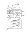
- 1 is a schematic diagram showing an internal configuration of an embodiment of an image processing apparatus according to the present invention.
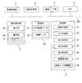
- 1 is a block diagram illustrating an example of an electrical configuration of an image processing apparatus.
- the image processing apparatus 1 is a multifunction machine having an image reading function, a facsimile function, an image forming function, and the like.
- an image processing apparatus 1 includes an image reading unit 2, a document cover 3, an automatic document feeder (hereinafter referred to as ADF) 4, an image forming unit 5, and an operation display unit 6 (FIG. 1). 2), a paper feed cassette 7, a communication interface (I / F) unit 8 (see FIG. 2), and a control unit 9 (see FIG. 2) for controlling them.
- ADF automatic document feeder
- I / F communication interface
- control unit 9 see FIG. 2 for controlling them.
- the image processing apparatus 1 that is a multifunction peripheral is illustrated and described as an example of the image processing apparatus according to the present invention. This corresponds to the image processing apparatus according to the invention.
- the image reading unit 2 executes image reading processing for reading image data from a document.
- the image reading unit 2 includes a contact glass 10, a reading unit 11, mirrors 12 and 13, an optical lens 14, a CCD (Charge Coupled15Device) 15, and the like.
- CCD Charge Coupled15Device
- the reading unit 11 includes an LED light source 16 and a mirror 17 and is configured to be movable in the sub-scanning direction 18 (left and right direction in FIG. 1) by a moving mechanism (not shown) using a driving motor such as a stepping motor. Yes.
- a driving motor such as a stepping motor.
- the mirror 17 reflects the reflected light reflected from the back surface of the document or the document cover 3 toward the mirror 12 when light is irradiated from the LED light source 16.
- the light reflected by the mirror 17 is guided to the optical lens 14 by the mirrors 12 and 13.
- the optical lens 14 collects incident light and makes it incident on the CCD 15.
- the CCD 15 is a photoelectric conversion element that converts the received light into an electrical signal (voltage) corresponding to the amount of light (intensity of luminance) and outputs it to the control unit 9.
- image data of the document is generated by performing image processing on the electrical signal from the CCD 15.
- a contact type image sensor CIS: Contact Image Sensor
- CIS Contact Image Sensor
- the image reading unit 2 is provided with a document cover 3 so as to be rotatable.
- a document cover 3 When the document cover 3 is rotated, the contact glass 10 on the upper surface of the image reading unit 2 is opened and closed.
- the rotation support portion of the document cover 3 is provided with a cover open detection sensor (not shown) such as a limit switch.
- cover open detection sensor such as a limit switch.
- the reading of the document image by the image reading unit 2 is performed according to the following procedure. First, the document is placed on the contact glass 10, and then the document cover 3 is closed. Thereafter, when an image reading instruction is input from the operation display unit 6, one line of light is sequentially emitted from the LED light source 16 while moving the reading unit 11 to the right in the sub-scanning direction 18. Then, reflected light from the back of the document or document cover 3 is guided to the CCD 15 via the mirrors 17, 12, 13 and the optical lens 14, and light amount data corresponding to the amount of light received by the CCD 15 is sequentially output to the control unit 9. Is done. When the light amount data in the entire area irradiated with light is obtained, the control unit 9 processes the light amount data to generate document image data from the light amount data. This image data is image data constituting a rectangular image.
- the ADF 4 is provided on the document cover 3.
- the ADF 4 sequentially conveys one or more originals set on the original setting unit 19 by a plurality of conveyance rollers so that the automatic original reading position determined on the contact glass 10 passes rightward in the sub-scanning direction 18. Move the document.
- the reading unit 11 is disposed below the automatic document reading position, and the image of the moving document is read by the reading unit 11 at this position.
- the document setting unit 19 is provided with a mechanical document detection sensor (not shown) capable of outputting a contact signal. When a document is set on the document setting unit 19, the document detection sensor operates, The detection signal (original detection signal) is output to the control unit 9.
- the image forming unit 5 is based on image data read by the image reading unit 2 or a print job input from an information processing apparatus such as an external personal computer through a communication I / F unit 8.
- An electrophotographic image forming unit that executes image forming processing (printing processing).
- the image forming unit 5 includes a photosensitive drum 20, a charging unit 21, a developing unit 22, a toner container 23, a transfer roller 24, a charge removing unit 25, a fixing roller 26, a pressure roller 27, and the like.
- the electrophotographic image forming unit 5 will be described as an example.
- the image forming unit 5 is not limited to the electrophotographic type, and may be an ink jet recording type or other than that. The recording method or the printing method may be used.
- the image forming process for the printing paper supplied from the paper feed cassette 7 is performed in the following procedure.
- LSU laser scanner unit
- an electrostatic latent image is formed on the surface of the photosensitive drum 20.
- the electrostatic latent image on the photosensitive drum 20 is developed (visualized) as a toner image by the developing unit 22.
- the developing unit 22 is supplied with toner (developer) from the toner container 23.
- the toner image formed on the photosensitive drum 20 is transferred onto the printing paper by the transfer roller 24. Thereafter, the toner image transferred to the printing paper is heated and fused by the fixing roller 26 when the printing paper passes between the fixing roller 26 and the pressure roller 27 and is discharged. The electric potential of the photosensitive drum 20 is neutralized by the neutralization unit 25.
- the communication I / F unit 8 is an interface that executes data communication with an external device connected to the image processing apparatus 1 via a communication network such as the Internet or a LAN.
- the storage unit 28 includes a nonvolatile memory such as a hard disk drive (HDD).
- HDD hard disk drive
- the storage unit 28 stores image data D1 of various characters such as hiragana, katakana, alphabets, and numbers in advance.
- the storage unit 28 also stores in advance dictionary data D2 that collects words (words, words, phrases) composed of character strings of these various characters.
- the image data D1 and the dictionary data D2 are used for a booklet process described later.
- the control unit 9 includes a CPU (Central Processing Unit) and a memory having a ROM (Read Only Memory) and a RAM (Random Access Memory).
- the CPU is a processor that executes various arithmetic processes.
- the ROM is a non-volatile storage unit in which information such as a control program for causing the CPU to execute various processes is stored in advance.
- the RAM is a volatile storage unit, and is a storage unit used as a temporary storage memory (work area) for various processes executed by the CPU.
- the control unit 9 controls the operation of each unit by the CPU executing a program stored in the ROM.
- the operation display unit 6 includes a display unit 29 and an operation unit 30.
- the display unit 29 is configured by, for example, a color liquid crystal display, and displays various types of information to the user who operates the operation display unit 6.
- the operation unit 30 includes various push button keys disposed adjacent to the display unit 29, a touch panel sensor disposed on the display screen of the display unit 29, and the like, and various instructions are input by the user of the image processing apparatus 1. The When the user performs an operation on the operation display unit 6 in order to execute an image reading operation or an image forming operation, the operation signal is output from the operation display unit 6 to the control unit 9.
- the image reading unit 2 the image forming unit 5, the operation display unit 6, the communication I / F unit 8, the storage unit 28, and the control unit 9 can mutually input and output data.
- Each component is connected through the data bus 200.
- the image processing apparatus 1 has a booklet copy mode in which a copy operation is performed with a plurality of documents constituting the booklet as reading targets.
- the operation display unit 6 is provided with a setting button 31 (see FIG. 2) for setting the image processing apparatus 1 to the booklet copy mode.
- the setting button 31 When the setting button 31 is operated, the image processing apparatus 1 enters a booklet copy mode.
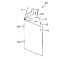
- FIG. 3 An example of a booklet is shown in FIG.
- a plurality of staples 500 are pierced along a folding line at the center in the long side direction of a stacked document sheet, and the stacked document sheet is folded at the folding line.
- This is a binding type booklet (hereinafter referred to as a saddle stitch booklet 400).
- a saddle stitch booklet 400 shown in FIG. 3 includes three originals P1 to P3, and the originals P1, P2, and P3 are positioned in order from the outside. Images of the first and twelfth pages are formed on the first side of the document P1, and images of the second and eleventh pages are formed on the second side.
- Images of the third and tenth pages are formed on the first surface of the document P2, and images of the fourth and ninth pages are formed on the second surface. Images of the fifth and eighth pages are formed on the first surface of the document P3, and images of the sixth and seventh pages are formed on the second surface.
- FIG. 4A the originals constituting such a saddle stitch booklet 400 are separated by removing the staple needle 500, and these are set in the booklet copy mode setting state. There may be a case where an instruction to copy a document is issued.
- FIGS. 4A to 4D indicate the page numbers in the saddle stitch booklet 400.
- each image includes two pages of images 6.
- the read image 100 for the number of sheets is generated.
- the images of two pages adjacent to each other in the spread state may have continuity and relevance of the drawn images.
- the image of each page in the generated read image is in a state where the page order is dispersed as shown in FIG. 4B.
- the arrangement order of the images in the newly generated printed material is in a disjoint state, and the user can draw a drawing image having continuity and relevance. Cannot be viewed as a single unit.
- the image processing apparatus 1 when the images of two adjacent pages on the left and right in the spread state have continuity and relevance of the drawn images, the drawn images are integrally formed in a beautiful form. It has a booklet processing function for generating visually recognized printed matter.
- a booklet processing function for generating visually recognized printed matter.
- the control unit 9 causes the CPU to execute a program so that the image dividing unit 32, the pair creation unit 33, the first determination unit 34, the second determination unit, as shown in FIG. 35, a third determination unit 36, an image combining unit 37, and an image size adjusting unit 38.
- the image dividing unit 32 is an example of an image dividing unit
- the pair creating unit 33 is an example of a pair creating unit.
- the first determination unit 34 is an example of a first determination unit
- the second determination unit 35 is an example of a second determination unit.
- the third determination unit 36 is an example of a third determination unit
- the image combination unit 37 is an example of an image combination unit
- the image size adjustment unit 38 is an example of an image size adjustment unit.
- the image dividing unit 32 functions when the booklet copy mode is set. As shown in FIG. 4B, the image dividing unit 32 acquires each read image 100 obtained by the reading operation of the image reading unit 2 with respect to each document constituting the saddle stitch booklet 400 from the image reading unit 2, and reads the read image. 100 is divided at the center in the long side direction (the position of the dotted line shown in FIG. 4B). Thereby, as shown in FIG. 4C, each read image 100 is divided for each page in the saddle stitch booklet 400.
- the image after the division by the image dividing unit 32 is referred to as a divided image 150.
- the image dividing unit 32 is an example of an image acquisition unit.
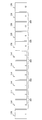
- the pair creation unit 33 arranges the divided images 150 in the order of the pages of the saddle stitch booklet 400. Specifically, the pair creation unit 33 detects the page number included in each divided image 150 by the character recognition function using the character image data D1 stored in the storage unit 28, and based on the detected page number. Thus, the divided images 150 are arranged in page order. In FIG. 4D, the divided images 150 from the first page to the twelfth page are arranged in ascending order from the left.
- the pair creation unit 33 creates a pair for each pair of adjacent pages when the saddle-stitched booklet 400 is in a spread state for each of the arranged divided images 150.
- the pair creation unit 33 excludes the first page and the last page corresponding to the front and back covers of the saddle stitch booklet 400 from pair creation targets.
- FIG. 4D shows a result of the pair creation unit 33 creating a pair for pages 2 to 11 except for the first and twelfth pages corresponding to the front and back covers of the saddle stitch booklet 400. ... 305 are set.
- the first determination unit 34 for each of the pairs 301 to 305 of the divided image 150, has a band-like region having a predetermined width including the divided end portion 125 for the two divided images 150 set as a pair.
- 102 and 103 hatchched areas are set as the following processing targets.
- segmentation edge part 125 is an example of a boundary part.
- the first determination unit 34 determines the presence / absence of a drawn image in the strip regions 102 and 103.
- the drawing image is, for example, a line drawing or a character image.
- the first determination unit 34 determines that there is a drawn image when a predetermined number or more of pixels having a pixel value equal to or less than a predetermined value (a density equal to or greater than a certain value) are present in the band-like regions 102 and 103.
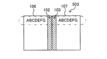
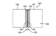
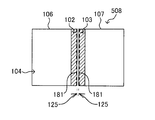
- FIGS. 6A to 6H An example of two divided images 106 and 107 set as a pair is shown in FIGS. 6A to 6H.
- 6A to 6E show an example of a pair 501 to 505 of two divided images 106 and 107 having no drawn image in the band-like regions 102 and 103.
- FIGS. 6F to 6H show an example of a pair 506 to 508 of two divided images 106 and 107 having drawn images in the band-like regions 102 and 103.
- the first determination unit 34 determines that the image data in the strip regions 102 and 103 is uniform white data. Based on this, it is determined that there is no drawn image in the strip regions 102 and 103.
- the first determination unit 34 is based on the fact that the image data in the strip regions 102 and 103 is different depending on the part. Then, it is determined that there is a drawn image in the strip regions 102 and 103.
- the first determining unit 34 determines whether or not the drawn image is a boundary line between the divided images 106 and 107.
- the boundary line is an example of a boundary image, and is, for example, a solid line or a dotted line.
- 6G and 6H show the pairs 507 and 508 of the two divided images 106 and 107 when the drawn images in the band-like regions 102 and 103 are the boundary lines 180 and 181, respectively.
- the boundary lines 180 and 181 pass, for example, each center point of the pair of long sides 101 of the read image 100 by the image reading unit 2, as shown in FIGS. 6G and 6H, the boundary lines 180 and 181 are the divided images.
- the first determination unit 34 when the pixels having a pixel value equal to or smaller than a predetermined value are lined up in the above-described form along the divided end portion 125 in the band-shaped regions 102 and 103, The rendered image in 103 is determined as a boundary line between images in the image areas 104 and 105.
- a pair 506 shown in FIG. 6F is an image of alphabet letters “A” and “E” in the drawn images in the band-like regions 102 and 103, not the boundary line images.
- the first determination unit 34 determines that the drawn image in the strip regions 102 and 103 is not the image of the boundary line.
- the pair of the two divided images is the pairs 507 and 508 shown in FIGS. 6G and 6H, the first determination unit 34 determines that the drawn images in the strip regions 102 and 103 are the boundary lines.
- the second determination unit 35 determines the presence or absence of drawing continuity with respect to the drawn images of characters in the divided images 106 and 107.
- the drawing continuity indicates a character (character string) that is continuous so that a character drawing image in each of the divided images 106 and 107 forms one word or one phrase (phrase or phrase). It means that it is an image.
- the processing of the second determination unit 35 will be specifically described.
- the second determination unit 35 first determines the presence or absence of a drawn image in each of the divided images 106 and 107. If the second determination unit 35 determines that there is a drawn image in each of the divided images 106 and 107, the second determining unit 35 detects whether the drawn image indicates a character and, if it indicates a character, which character it indicates. .
- the character image data D1 (see FIG. 2) of various characters such as hiragana is stored in the storage unit 28 in advance. The second determination unit 35 performs the above-described character detection by comparing the detected drawn image with the character image data D1.
- the second determination unit 35 detects the character drawing images in the divided images 106 and 107
- the second determination unit 35 determines the presence or absence of drawing continuity with respect to the character drawing images in the image regions 104 and 105. That is, the second determination unit 35 determines whether or not the drawn images of the characters in the divided images 106 and 107 are images each showing a continuous character (character string) so as to form one word.
- dictionary data D2 (see FIG. 2) is stored in the storage unit 28 in advance. The second determination unit 35 performs the above-described word detection by comparing the character string with the dictionary data D2.
- the second determination unit 35 determines that there is drawing continuity with respect to the drawn images of the characters in the divided images 106 and 107. On the other hand, when the detected character string is not registered as a word in the dictionary data, the second determination unit 35 determines that there is no drawing continuity.
- the second determination unit 35 determines that there is no drawing continuity for the pair 501 shown in FIG. 6A.
- the characters “TEST1” are formed in the left divided image 106, and the characters “TEST2” are formed in the right divided image 107.
- a group of character strings formed by a series of characters “TEST1” and characters “TEST2” does not constitute one word or phrase. Therefore, the second determination unit 35 determines that there is no drawing continuity for the pair 501 shown in FIG. 6B.
- the characters “ABCDEFG” are formed in both the left divided image 106 and the right divided image 107.
- a company name or the like may be formed by default setting.
- a group of character strings formed by a series of these two “ABCDEFG” characters does not constitute one word or phrase. Therefore, the second determination unit 35 determines that there is no drawing continuity for the pair 503 illustrated in FIG. 6C.
- the characters “ABCDEFG” are formed only in the right divided image 107, and nothing is drawn in the left divided image 106. Thus, when there is no drawing image in one area
- a character “TE” is formed in the left divided image 106 and a character “ST” is formed in the right divided image 107.
- a group of character strings formed by a series of characters “TE” and “ST” constitutes one word “TEST”. Therefore, the second determination unit 35 determines that the pair 505 illustrated in FIG. 6E has drawing continuity.
- the third determination unit 36 determines whether or not the two divided images 106 and 107 related to the pair should be combined based on the detection result by the first determination unit 34 and the determination result by the second determination unit 35.
- the first determination unit 34 does not determine that there is a drawn image in the strip regions 102 and 103, and the second determination unit 35 draws characters in the divided images 106 and 107. If it is determined that the image has no drawing continuity, it is determined that it is not necessary to combine the two divided images 106 and 107. Therefore, when the pair of the two divided images 106 and 107 is the pair 501 to 504 shown in FIGS. 6A to 6D, the third determination unit 36 sets the two divided images 106 and 107 related to the pair 501 to 504 to each other. It is determined that there is no need to combine.
- the first determination unit 34 determines that there is no drawing image in the strip regions 102 and 103, and the second determination unit 35 continuously draws the character drawing images in the divided images 106 and 107.
- the third determination unit 36 determines that the two divided images 106 and 107 related to the pair 505 should be combined.
- the third determination unit 36 determines the two divided images 106 regardless of the determination result by the second determination unit 35. , 107 need not be combined. Therefore, when the pair of the two divided images 106 and 107 is the pair 507 and 508 shown in FIGS. 6G and 6H, the third determination unit 36 sets the two divided images 106 and 107 related to the pair 507 and 508 to each other. It is determined that there is no need to combine.
- the third determination unit 36 determines that the two divided images 106 and 107 should be combined when the first determination unit 34 detects an image other than the boundary line in the strip regions 102 and 103. . Therefore, when the pair of the two divided images 106 and 107 is the pair 506 shown in FIG. 6F, the third determination unit 36 determines that the two divided images 106 and 107 related to the pair 506 should be combined.
- the image combining unit 37 combines the images of the pair of divided images 106 and 107 determined to be combined by the third determining unit 36, as shown in the upper and middle diagrams of FIG. Regarding the pairs 501 to 508 shown in FIGS. 6A to 6H, the image combining unit 37 determines that the two divided images 106 and 107 related to the pairs 505 and 506 shown in FIGS. 6E and 6F that are determined to be combined. Join. The image combining unit 37 combines the two divided images 106 and 107 related to the pairs 505 and 506 at the divided end 125.
- the image combining unit 37 When combining the divided images 106 and 107, the image combining unit 37 performs image processing such as aligning the positions of the drawn image of the divided image 106 and the drawn image of the divided image 107, and adjusting the density. The image combining unit 37 outputs the combined image combined in this way to the image size adjusting unit 38.
- the image size adjustment unit 38 performs size adjustment to match the image size of the combined image by the image combining unit 37 with the image size of the uncombined image.
- the image size adjustment unit 38 adjusts the image size of the combined image to the image size of the image that has not been combined. For example, as shown in the middle diagram and the lower diagram in FIG. 7, when the two divided images 106 and 107 that are combined are images each having an A4 size, the combined image has an A3 size.
- the image size adjustment unit 38 performs a process of reducing the combined image of A3 size to the horizontal A4 size that is the image size of the uncombined image.
- FIG. 8 is a flowchart of the booklet process performed by the control unit 9.
- steps S1, S2,... present processing procedure (step) numbers.
- step S1 When the user issues a copy instruction in the booklet copy mode (YES in step S1), the image reading unit 2 reads an image of the document (step S2).
- the image dividing unit 32 divides each read image 100 obtained by this reading operation at the center in the long side direction (step S3). Thus, each read image 100 is divided for each page in the saddle stitch booklet 400, and divided images 150 (106, 107) are generated.
- the pair creation unit 33 performs processing for creating a pair for each of the divided images 106 and 107 (step S4). That is, the pair creation unit 33 first arranges the divided images 106 and 107 in the page order of the saddle stitch booklet 400. Further, the pair creation unit 33 detects the page number included in each of the divided images 106 and 107 by the character recognition function using the character image data D1 stored in the storage unit 28. The pair creation unit 33 arranges the divided images 106 and 107 in page order based on the detected page number. Then, the pair creation unit 33 creates a pair for each pair of adjacent pages when the saddle-stitched booklet 400 is in a spread state for the arranged divided images 106 and 107. At this time, the pair creation unit 33 attaches a pair number to each pair.
- control unit 9 sets the pair having the pair number “1” as a processing target (step S5).
- the first determination unit 34 determines whether or not the two divided images 106 and 107 related to the pair are drawn in the strip regions 102 and 103 (step S6).
- the second determination unit 35 detects the character drawn image in the divided images 106 and 107. (Step S7). When the second determination unit 35 detects that there is a character drawing image in each of the divided images 106 and 107, whether or not a character string formed by a continuation of these characters forms one word, that is, Then, it is determined whether or not there is drawing continuity (step S8).
- step S8 When it is determined in step S8 that the second determination unit 35 has drawing continuity (NO in step S8), the third determination unit 36 receives this series of determinations, and the two divided images 106, 107 are determined to be combined (step S9). In response to the determination result of the third determination unit 36, the image combining unit 37 combines the two divided images 106 and 107 (step S10), and proceeds to the process of step S12.
- step S8 If it is determined in step S8 that the second determination unit 35 has no drawing continuity (YES in step S8), the control unit 9 skips steps S9 and S10 and performs step S12. Do.
- step S6 if the first determination unit 34 determines that the image is drawn in the strip regions 102 and 103 (YES in step S6), the first determination unit 34 determines whether the drawn image is the image of the boundary line (step S6). S11). As a result, if the first determination unit 34 determines that the drawn image is not the image of the boundary line (NO in step S11), the process proceeds to step S9. If the first determination unit 34 determines that the drawn image is an image of the boundary line (YES in step S11), the process proceeds to step S12.
- step S12 the control unit 9 determines whether or not the processing in steps S6 to S11 has been completed for all pairs. If the control unit 9 determines that the processing in steps S6 to S11 has not been completed for all pairs (NO in step S11), the control unit 9 sets a pair with a pair number incremented by 1 as a processing target (step S13). Steps S6 to S11 are performed for the pair.
- the image size adjustment unit 38 sets the image size of the images combined by the image combining unit 37. A size adjustment is performed to match the image size of the uncombined image (step S14). Then, the control unit 9 outputs these images to the image forming unit 5 (step S15).
- the image forming unit 5 prints these images on a sheet that matches the image size of the uncombined image.
- the image forming unit 5 prints each image on each printing surface of the printing paper.
- the printing form at this time may be single-sided printing or double-sided printing.
- the image processing apparatus 1 divides the image read by the image reading unit 2 at the center in the long side direction. Further, the divided images 106 and 107 are rearranged in the page order to create a pair. Moreover, the presence or absence of the drawing image in the strip
- the image processing apparatus 1 displays the two divided images 106 and 107 even if they are not drawn in the strip regions 102 and 103. Join.
- these two divided images 106 and 107 are arranged side by side on one printing surface of one sheet. Thereby, the user can visually recognize two drawing images having drawing continuity integrally.
- the two divided images 106 and 107 are combined after performing image processing such as aligning the positions of the drawn image of the divided image 106 and the drawn image of the divided image 107 and adjusting the density. .
- image processing such as aligning the positions of the drawn image of the divided image 106 and the drawn image of the divided image 107 and adjusting the density.
- the image processing apparatus 1 combines the two divided images 106 and 107 even when the drawn image is an image other than the boundary line when the image is drawn in the band-like regions 102 and 103. To do. Also by this, it is possible to generate an image having a good image quality from the document image including the drawing images for two pages of the saddle stitch booklet 400.
- the image size of the combined image is matched with the image size of the image that has not been combined.
- the combined image by the image combining unit 37 can be printed out according to the paper of that size.
- the first page as the cover and the 12th page as the back cover are often read separately.
- seven read images 100 each including two pages of images are generated.
- Half of the read images 100 obtained by reading the images on the first page and the twelfth page are so-called black solid images.
- the shaded area in FIG. 9B shows the solid black image.
- the image dividing unit 32 sets each read image 100 obtained by the reading operation of the image reading unit 2 with respect to each document constituting the saddle stitch booklet 400 in the center in the long side direction (shown in FIG. 9B). (Dotted line position).
- each read image 100 is divided for each page in the saddle stitch booklet 400, and a divided image 150 is generated. Then, the divided images 150 are arranged in the page order of the saddle stitch booklet 400. At this time, the solid black divided image 150 is deleted.
- the pair creation unit 33 creates a pair for each pair of adjacent pages when the saddle-stitched booklet 400 is in a spread state for each of the arranged divided images 150.
- the pair creation unit 33 also excludes the first page and the last page corresponding to the front and back covers of the saddle stitch booklet 400 from the pair creation target.
- FIG. 4D shows a result of the pair creation unit 33 creating a pair for pages 2 to 11 except for the first and twelfth pages corresponding to the front and back covers of the saddle stitch booklet 400. ... 305 are set. Thereafter, the same processing as in the first embodiment may be performed.
- the booklet to be processed in this case is not limited to the saddle-stitch type booklet, but is also a so-called single-stitched booklet in which a plurality of documents each having an image for one page formed on one side or both sides is formed by left-stitching or top-stitching. included.
- the same effects as described above can be obtained by performing a series of booklet processes including the division process shown in FIGS. 9A to 9D. Can do.
- the image read by the image reading unit 2 is the target image for booklet processing.
- a received image received from another device can be a target for booklet processing.
- the image dividing unit 32 is provided in the control unit 9 of the image processing apparatus 1.
- the communication interface unit 8 functions as an image acquisition unit.
- the use of the image after the booklet processing is for print output, but the use is not limited to print output.
- it may be used for transmission to another device, or may be used for storage by the own device (image processing apparatus 1).
- the image size of the image combined by the image combining unit 37 is adjusted to the image size of the image that has not been combined.
- the image size of the image that is not combined may be matched with the image size of the image combined by the image combining unit 37. In this case, such image size adjustment is not essential, and size adjustment may not be performed.
Landscapes
- Engineering & Computer Science (AREA)
- Multimedia (AREA)
- Signal Processing (AREA)
- Editing Of Facsimile Originals (AREA)
- Character Input (AREA)
- Facsimiles In General (AREA)
Abstract
Description
ラム20の表面に印刷ジョブに含まれる画像データに基づく光が照射される。これにより、感光体ドラム20の表面に静電潜像が形成される。そして、感光体ドラム20上の静電潜像は現像部22によりトナー像として現像(可視像化)される。なお、現像部22には、トナーコンテナ23からトナー(現像剤)が補給される。続いて、感光体ドラム20に形成されたトナー像は転写ローラー24により印刷用紙に転写される。その後、印刷用紙に転写されたトナー像は、その印刷用紙が定着ローラー26及び加圧ローラー27の間を通過して排出される際に定着ローラー26で加熱されて溶融定着する。なお、感光体ドラム20の電位は除電部25で除電される。
Claims (7)
- 冊子を構成する複数の原稿のページ毎の画像を取得する画像取得部と、
前記画像取得部により取得された複数の画像を前記冊子のページ順に配列し、この配列された各画像に対し、前記冊子を見開き状態としたときに隣り合う一対のページ毎にペアを作成するペア作成部と、
前記ペア作成部により作成された各ペアにおける2つの画像に対し、この2つの画像同士の境界部分を含む所定幅の帯状領域における描画像の有無を判定する第1判定部と、
前記2つの画像同士の描画連続性の有無を判定する第2判定部と、
前記第1判定部による判定結果と前記第2判定部による判定結果とに基づいて、前記2つの画像を結合すべきか否かを判定する第3判定部と、
前記第3判定部により前記2つの画像を結合すべきであると判定されると、この2つの画像を結合する画像結合部と、を備える画像処理装置。 - 前記第3判定部は、前記第1判定部によって前記帯状領域に描画像が無いと判定され、且つ、前記第2判定部により前記描画連続性があると判定された場合、前記2つの画像を結合すべきであると判定する請求項1に記載の画像処理装置。
- 前記第3判定部は、前記第1判定部により前記帯状領域に描画像があると判定され、前記第1判定部によりその描画像が前記2つの画像間の境界を示す境界画像以外の画像であると判定された場合、前記第2判定部による判定結果に拘わらず、前記2つの画像を結合すべきであると判定する請求項1に記載の画像処理装置。
- 前記画像結合部により結合された画像の画像サイズと前記画像結合部により結合されなかった画像の画像サイズとを同じサイズに調整する画像サイズ調整部を更に備える請求項1に記載の画像処理装置。
- 前記冊子は、積層状態で2つ折りにされた複数の原稿が折り目又はその近傍で綴じられてなる中綴じ冊子であり、
前記画像取得部は、前記中綴じ冊子の綴じ状態を解除することにより互いに分離された複数の原稿がそれぞれ読み取られた画像であって前記中綴じ冊子の2ページ分の描画像を含む画像を前記中綴じ冊子のページ毎に分割することにより前記ページ毎の画像を取得する画像分割部であり、
前記ペア作成部は、前記画像分割部により分割された各分割画像を前記ペアの作成対象とする請求項1に記載の画像処理装置。 - 前記画像取得部は、前記冊子が見開き状態で読み取られた画像であって前記中綴じ冊子の2ページ分の描画像を含む画像を前記中綴じ冊子のページ毎に分割することにより前記ページ毎の画像を取得する画像分割部であり、
前記ペア作成部は、前記画像分割部により分割された各分割画像を前記ペアの作成対象とする請求項1に記載の画像処理装置。 - 冊子を構成する複数の原稿のページ毎の画像を取得する第1ステップ、
前記第1ステップで取得された画像を前記冊子のページ順に配列し、この配列された各画像に対し、前記冊子を見開き状態としたときに隣り合う一対のページ毎にペアを作成する第2ステップ、
前記第2ステップで作成された各ペアにおける2つの画像に対し、この2つの画像同士の境界部分を含む所定幅の帯状領域における描画像の有無を判定する第3ステップ、
前記2つの画像同士の描画連続性の有無を判定する第4ステップ、
前記第3ステップでの判定結果と前記第4ステップでの判定結果とに基づいて、前記2つの画像を結合すべきか否かを判定する第5ステップ、
前記第5ステップにおいて前記2つの画像を結合すべきであると判定されると、この2つの画像を結合する第6ステップ、を備える画像処理方法。
Priority Applications (2)
| Application Number | Priority Date | Filing Date | Title |
|---|---|---|---|
| JP2015545254A JP6177344B2 (ja) | 2013-10-31 | 2014-10-29 | 画像処理装置、及び画像処理方法 |
| US15/033,585 US10218877B2 (en) | 2013-10-31 | 2014-10-29 | Image processing apparatus, and image processing method |
Applications Claiming Priority (2)
| Application Number | Priority Date | Filing Date | Title |
|---|---|---|---|
| JP2013-226854 | 2013-10-31 | ||
| JP2013226854 | 2013-10-31 |
Publications (1)
| Publication Number | Publication Date |
|---|---|
| WO2015064609A1 true WO2015064609A1 (ja) | 2015-05-07 |
Family
ID=53004210
Family Applications (1)
| Application Number | Title | Priority Date | Filing Date |
|---|---|---|---|
| PCT/JP2014/078707 Ceased WO2015064609A1 (ja) | 2013-10-31 | 2014-10-29 | 画像処理装置、及び画像処理方法 |
Country Status (3)
| Country | Link |
|---|---|
| US (1) | US10218877B2 (ja) |
| JP (1) | JP6177344B2 (ja) |
| WO (1) | WO2015064609A1 (ja) |
Cited By (1)
| Publication number | Priority date | Publication date | Assignee | Title |
|---|---|---|---|---|
| JP2023124453A (ja) * | 2022-02-25 | 2023-09-06 | セイコーエプソン株式会社 | 画像読取システム、画像読取装置、画像読取方法及びプログラム |
Citations (3)
| Publication number | Priority date | Publication date | Assignee | Title |
|---|---|---|---|---|
| JP2009094925A (ja) * | 2007-10-11 | 2009-04-30 | Fuji Xerox Co Ltd | 画像処理プログラム及び画像処理装置 |
| JP2012004859A (ja) * | 2010-06-17 | 2012-01-05 | Sharp Corp | ドキュメント作成装置、ドキュメント作成方法、ドキュメント作成プログラム及び記録媒体 |
| JP5327492B1 (ja) * | 2012-08-22 | 2013-10-30 | 富士ゼロックス株式会社 | 画像処理装置および画像処理プログラム |
Family Cites Families (3)
| Publication number | Priority date | Publication date | Assignee | Title |
|---|---|---|---|---|
| JP3593676B2 (ja) | 1999-06-28 | 2004-11-24 | 村田機械株式会社 | 原稿読取記録装置 |
| JP3912012B2 (ja) * | 2001-01-24 | 2007-05-09 | 富士ゼロックス株式会社 | イメージ分割装置 |
| JP5803063B2 (ja) * | 2010-07-21 | 2015-11-04 | 株式会社リコー | 画像処理システム、画像処理装置、画像処理プログラム及び画像処理方法 |
-
2014
- 2014-10-29 US US15/033,585 patent/US10218877B2/en active Active
- 2014-10-29 JP JP2015545254A patent/JP6177344B2/ja not_active Expired - Fee Related
- 2014-10-29 WO PCT/JP2014/078707 patent/WO2015064609A1/ja not_active Ceased
Patent Citations (3)
| Publication number | Priority date | Publication date | Assignee | Title |
|---|---|---|---|---|
| JP2009094925A (ja) * | 2007-10-11 | 2009-04-30 | Fuji Xerox Co Ltd | 画像処理プログラム及び画像処理装置 |
| JP2012004859A (ja) * | 2010-06-17 | 2012-01-05 | Sharp Corp | ドキュメント作成装置、ドキュメント作成方法、ドキュメント作成プログラム及び記録媒体 |
| JP5327492B1 (ja) * | 2012-08-22 | 2013-10-30 | 富士ゼロックス株式会社 | 画像処理装置および画像処理プログラム |
Cited By (1)
| Publication number | Priority date | Publication date | Assignee | Title |
|---|---|---|---|---|
| JP2023124453A (ja) * | 2022-02-25 | 2023-09-06 | セイコーエプソン株式会社 | 画像読取システム、画像読取装置、画像読取方法及びプログラム |
Also Published As
| Publication number | Publication date |
|---|---|
| JPWO2015064609A1 (ja) | 2017-03-09 |
| US10218877B2 (en) | 2019-02-26 |
| US20160269592A1 (en) | 2016-09-15 |
| JP6177344B2 (ja) | 2017-08-09 |
Similar Documents
| Publication | Publication Date | Title |
|---|---|---|
| US7869733B2 (en) | Image forming apparatus | |
| US9405257B2 (en) | Printing control apparatus that controls printing order | |
| US20100123940A1 (en) | Image forming apparatus and image forming method | |
| JP5959494B2 (ja) | 画像処理装置、画像処理方法 | |
| US20210127018A1 (en) | Image forming apparatus to verify printed image with master image, image forming method, and storage medium | |
| US20210127017A1 (en) | Image forming apparatus with registered correct answer image to verify printed image, image forming method, and storage medium | |
| CN101320247A (zh) | 图像形成装置和记录介质 | |
| JP2021049744A (ja) | 画像形成装置、情報処理方法及びプログラム | |
| JP5449210B2 (ja) | 画像形成装置および画像形成プログラム | |
| CN103716486B (zh) | 电子设备、图像处理方法 | |
| JP6076495B2 (ja) | 画像処理装置、及び画像処理方法 | |
| JP6177344B2 (ja) | 画像処理装置、及び画像処理方法 | |
| US10897548B2 (en) | Image forming apparatus which reads page numbers of a document | |
| JP3805268B2 (ja) | 画像形成装置 | |
| JP6282139B2 (ja) | 画像形成装置、画像形成装置の制御方法、及びプログラム | |
| JP4259552B2 (ja) | 画像形成システム | |
| JP2005161837A (ja) | 画像形成システム | |
| US20250036335A1 (en) | Storage medium storing printer driver, information processing apparatus, and method of controlling the same | |
| US12298683B2 (en) | Image forming apparatus that determines a correction value for correcting an image position when an adjustment image is present and that selects an image bearing contact mode | |
| CN116137645B (zh) | 图像形成装置、后处理位置调整方法以及记录介质 | |
| JP2006031479A (ja) | 画像形成装置 | |
| JP2011004356A (ja) | 画像形成装置 | |
| JP5885766B2 (ja) | 画像処理装置 | |
| JP6141237B2 (ja) | 画像処理装置、画像処理方法 | |
| JP2008052349A (ja) | 画像形成装置 |
Legal Events
| Date | Code | Title | Description |
|---|---|---|---|
| 121 | Ep: the epo has been informed by wipo that ep was designated in this application |
Ref document number: 14857912 Country of ref document: EP Kind code of ref document: A1 |
|
| DPE1 | Request for preliminary examination filed after expiration of 19th month from priority date (pct application filed from 20040101) | ||
| ENP | Entry into the national phase |
Ref document number: 2015545254 Country of ref document: JP Kind code of ref document: A |
|
| WWE | Wipo information: entry into national phase |
Ref document number: 15033585 Country of ref document: US |
|
| NENP | Non-entry into the national phase |
Ref country code: DE |
|
| 122 | Ep: pct application non-entry in european phase |
Ref document number: 14857912 Country of ref document: EP Kind code of ref document: A1 |