WO2015064148A1 - レンズ保持具 - Google Patents
レンズ保持具 Download PDFInfo
- Publication number
- WO2015064148A1 WO2015064148A1 PCT/JP2014/067040 JP2014067040W WO2015064148A1 WO 2015064148 A1 WO2015064148 A1 WO 2015064148A1 JP 2014067040 W JP2014067040 W JP 2014067040W WO 2015064148 A1 WO2015064148 A1 WO 2015064148A1
- Authority
- WO
- WIPO (PCT)
- Prior art keywords
- head
- lens holder
- seal member
- wall surface
- internal space
- Prior art date
- Legal status (The legal status is an assumption and is not a legal conclusion. Google has not performed a legal analysis and makes no representation as to the accuracy of the status listed.)
- Ceased
Links
Images





Classifications
-
- B—PERFORMING OPERATIONS; TRANSPORTING
- B24—GRINDING; POLISHING
- B24B—MACHINES, DEVICES, OR PROCESSES FOR GRINDING OR POLISHING; DRESSING OR CONDITIONING OF ABRADING SURFACES; FEEDING OF GRINDING, POLISHING, OR LAPPING AGENTS
- B24B13/00—Machines or devices designed for grinding or polishing optical surfaces on lenses or surfaces of similar shape on other work; Accessories therefor
- B24B13/005—Blocking means, chucks or the like; Alignment devices
Definitions
- the present invention relates to a lens holder for holding a lens in grinding or polishing processing of the lens.
- Patent Document 1 discloses a work holder capable of rotatably and tiltably supporting a kanzashi by a holder for supporting the work and capable of vacuum suction of the work.
- Patent Document 1 the holder holding the work is supported by the holder, the air introduction passage is formed in the inside of the container, a groove is formed on the outer periphery of the container, and an annular diaphragm is attached to the groove.
- the ring-shaped space (diaphragm chamber) which accommodates is formed in a holder (refer FIG. 1 of patent document 1).
- a processing tool a grinding or polishing tool having a desired spherical shape is brought into contact with the workpiece to rotate the processing tool.
- the work and the holder rotate following the movement of the processing tool, and the work can be ground or polished while the work is in close contact with the processing tool.
- the diaphragm is sucked and closely attached to the lower surface of the diaphragm chamber.
- the pilot chamber is in a vacuum state, and the work is attracted to the holder via the suction port.
- Patent Document 1 since there are spaces above and below the diaphragm, the suction loss at the time of exhausting the pilot chamber is large. In addition, since the fitting width between the groove and the diaphragm provided on the outer periphery of the kansai is small, the sealing performance is low. For this reason, there is a problem that it is difficult to maintain the adsorptive power to the work when transporting the work.
- the present invention has been made in view of the above, and it is an object of the present invention to provide a lens holder capable of reliably maintaining the suction force to a work.
- a lens holder includes a head portion for holding an optical member to be processed and a kanshishi for rotatably supporting the head portion.
- the kansai includes a shaft portion provided with an exhaust passage inside, a protruding portion provided to protrude to the outer peripheral side with respect to the shaft portion, a seal member provided on the protruding portion, and the shaft A support portion forming a part of a sphere provided at the tip of the portion, the head portion including a work receiving portion for holding the optical member, an internal space for accommodating the protrusion portion, and the shaft An opening which is larger than the diameter of the portion and smaller than the outer diameter of the projecting portion and which communicates the internal space with the outside of the head portion, and a suction hole which communicates the internal space with the workpiece receiving portion; A tip end receiving portion to which the support portion can abut; And said that you are.
- the seal member abuts against the inner wall surface of the head portion, and the opening is sealed.
- the inner wall surface is characterized in that the inner wall surface approaches the bottom surface of the inner space as it goes from the edge of the opening to the outer peripheral side.
- the inner wall surface has a spherical shape.
- the inner wall surface is shaped like a side surface of a truncated cone.
- the ball center of the support portion is lowered to the inner wall surface.
- the seal member is disposed such that the vertical line passes through the center of the cross section of the seal member.
- the seal member is provided on the projecting portion of the kansai that is accommodated in the internal space of the head portion, and the opening diameter of the internal space is smaller than the outer diameter of the projecting portion.
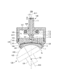
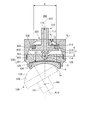
- FIG. 1 is a longitudinal sectional view showing a structure of a lens holder according to Embodiment 1 of the present invention.
- FIG. 2 is a longitudinal cross-sectional view showing the structure of the lens holder according to Embodiment 1 of the present invention (in a state in which the kanzashi is pulled upward).
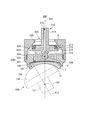
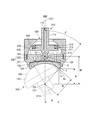
- FIG. 3 is a longitudinal sectional view showing the structure of the lens holder according to Embodiment 2 of the present invention.
- FIG. 4 is a longitudinal cross-sectional view showing the structure of the lens holder according to Embodiment 2 of the present invention (in a state in which the kanzashi is pulled upward).
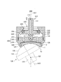
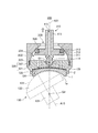
- FIG. 5 is a longitudinal sectional view showing the structure of the lens holder according to Embodiment 3 of the present invention.
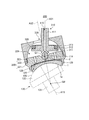
- FIG. 6 is a longitudinal cross-sectional view showing the structure of the lens holder according to Embodiment 3 of the present invention (in a state in which the kanzashi is pulled upward).
- FIG. 7 is a longitudinal sectional view showing a state in which an axial deviation occurs in the lens holder shown in FIG.
- FIG. 8 is a longitudinal cross-sectional view showing the lens holder shown in FIG. 7 in a state where the kansai is pulled upward.
- FIG. 9A is a longitudinal sectional view for explaining a method of determining the diameter of the opening of the head portion of the lens holder shown in FIG. 9B is a top view for explaining the method of determining the diameter of the opening of the head portion of the lens holder shown in FIG. 5.
- FIG. 10 is a longitudinal sectional view for explaining the method of determining the diameter of the seal member of the lens holder shown in FIG.
- FIG. 11 is a longitudinal sectional view for explaining the method of determining the height of the seal member of the lens holder shown in FIG.
- FIG. 12 is a longitudinal cross-sectional view for explaining the method of determining the height of the kansai fulcrum of the lens holder shown in FIG.
- FIG. 13 is a longitudinal cross-sectional view for explaining a lens manufacturing method using the lens holder shown in FIG.
- Embodiment 1 1 and 2 are longitudinal sectional views showing the structure of the lens holder according to Embodiment 1 of the present invention.
- the lens holder 100 according to the first embodiment when producing a lens from an optical member, the lens holder 100 is brought into contact with a processing tool 130 that rotates an optical member (work) 1 to be processed.
- a kansai 110 that rotatably supports the fulcrum 120.
- the processing tool 130 includes a grinding wheel shaft 131 and a grinding wheel 132 on which a processing surface 133 having a shape (for example, a convex spherical shape) corresponding to the spherical shape (for example, a concave spherical shape) of the workpiece 1 is formed. It is a tool equipped, and it is attached to the lens processing apparatus which is not shown in figure so that it may rotate around central axis A13.
- the kansai 110 comprises a cylindrical shaft portion 111 made of metal or alloy, a projecting portion 112 provided so as to project outward with respect to the axial portion 111, and a seal member provided on the projecting portion 112 And a support portion 114 provided at the tip of the shaft portion 111.
- the axis of rotational symmetry of the shaft portion 111 is taken as a central axis A11.
- an exhaust passage 115 extending along the central axis A11 is formed.
- One end of the exhaust passage 115 opens at the upper end surface of the shaft portion 111.
- the exhaust passage 115 is connected to a vacuum suction device (not shown).
- the exhaust passage 115 branches near the protrusion 112 and opens at a plurality of locations on the side surface of the shaft 111 below the protrusion 112.
- the exhaust passage 115 is opened at two locations on the side surface of the shaft portion 111, but may be opened at three or more locations.
- the exhaust passage 115 may be simply bent without being branched, and may be opened at one position on the side surface of the shaft portion 111.
- the protrusion 112 has a disk shape provided with a notch 116, and the seal member 113 is fixed to the notch 116.
- the seal member 113 has a ring shape with a circular cross section, and for example, silicone rubber (SR), nitrile rubber (NBR), chloroprene rubber (CR), ethylene propylene rubber (EPDM), styrene butadiene rubber (SBR), fluororubber ( FKM), is formed of an elastic material of butyl rubber (IIR).
- silicone rubber SR
- NBR nitrile rubber
- CR chloroprene rubber
- EPDM ethylene propylene rubber
- SBR styrene butadiene rubber
- FKM fluororubber
- IIR butyl rubber
- the protruding portion 112 is integrally formed with the shaft portion 111.
- the protruding portion 112 and the shaft portion 111 may be separately formed, and these may be combined.
- the protrusion 112 and the sealing member 113 may be integrally formed of the above-described elastic material, or may be integrally formed of a hard material such as Delrin (registered trademark) or Teflon (registered trademark). .
- the support portion 114 is in the shape of a part of a sphere.
- the kansai 110 is disposed such that the spherical portion of the support portion 114 abuts on a predetermined position of the head portion 120.
- the head portion 120 has a cylindrical shape with the central axis A12 as a rotational symmetry axis, and is constituted by a head main body lower portion 121 and a head main body upper portion 122 screwed together by a screw portion 123.
- a work receiving portion 124 which is a concave region for holding the work 1 is formed around the central axis A12.
- a suction hole 128 communicating the internal space 125 described later with the workpiece receiving portion 124 is formed.
- the backing material 2 is attached in advance to the work receiving portion 124, and the work 1 is brought into contact with the work receiving portion 124 via the backing material 2.
- the backing material 2 is a sheet-like member made of a resin material such as silicone rubber or the like, or a material obtained by applying anti-slip processing or adhesion processing to the surface of a base material made of resin such as polyester. An opening is formed in advance according to the position of the hole 128.
- the head portion 120 is formed with an internal space 125 large enough to accommodate the protrusion 112 of the kansai 110. Further, an opening 126 communicating the internal space 125 with the outside of the head portion 120 is formed at an end portion of the head portion 120 on the side of the head main body upper portion 122 around the central axis A12. The diameter of the opening 126 is larger than the diameter of the shaft portion 111 and smaller than the outer diameter of the projecting portion 112. The inner wall surface 127 around the opening 126 is in the same plane as the plane including the opening 126.
- a tip end receiving portion 129 for holding the support portion 114 of the kansai 110 is formed.
- the tip end receiving portion 129 has a concave spherical shape having substantially the same position and radius of curvature as the support portion 114.
- the head portion 120 is supported so as to be able to tilt and rotate with respect to the kansai 110.
- the position of the ball center of the tip end receiving portion 129 is referred to as a kanshishi fulcrum Q1.
- the head portion 120 is suspended when the shaft portion 111 of the kansai 110 is pulled upward as shown in FIG. Thereby, the seal member 113 abuts on the inner wall surface 127 around the opening 126 to seal the opening 126.
- the vacuum suction device connected to the exhaust path 115, the internal space 125 is depressurized, and the work 1 disposed in the work receiving portion 124 can be adsorbed and held.
- the protruding portion 112 that can be stored in the internal space 125 of the head portion 120 is provided on the kansai 110 and the head portion 120 is suspended by the kansai 110, the protruding portion 112 is Since the lens holder 100 is configured such that the internal space 125 is sealed by the seal member 113 provided in the above, the sealing property of the internal space 125 can be secured. Therefore, by evacuating the internal space 125 through the exhaust path 115, the internal space 125 can be sufficiently depressurized, and when the workpiece 1 is held and transported by the lens holder 100, etc. It is possible to reliably maintain the adsorption force.
- FIG.3 and FIG.4 is a longitudinal cross-sectional view which shows the structure of the lens holder which concerns on Embodiment 2 of this invention.
- the lens holder 200 according to the second embodiment includes a head unit 220 for holding the work 1 and a kanji 210 for supporting the head unit 220 in a tilting and rotatable manner.
- the kanjishi 210 has an exhaust passage 115 formed therein and a shaft portion 111 provided with a support portion 114 at its tip, and an outer peripheral side with respect to the shaft portion 111. It has a projecting portion 211 provided so as to project, and a seal member 213 disposed in the notch 212 of the projecting portion 211.
- the configuration and function of these parts are the same as in the first embodiment, and the dimensions of the projecting portion 211 and the seal member 213 are different from those in the first embodiment according to the shape of the internal space 224 of the head portion 220.
- the axis of rotational symmetry of the shaft portion 111 is taken as a central axis A21.
- the head portion 220 has a cylindrical shape with the central axis A22 as a rotational symmetry axis, and the head body lower portion 221 and the head body upper portion 222 screwed together by the screw portion 223.
- An internal space 224 of a size that can accommodate the projecting portion 211 of the kansai 210 is formed therein.
- a work receiving portion 124, a suction hole 128, and a tip end receiving portion 129 are formed in the lower portion 221 of the head main body.
- the head main body upper portion 222 is formed with an opening 225 communicating the internal space 224 with the outside of the head portion 220.
- the diameter of the opening 225 is larger than the diameter of the shaft portion 111 and smaller than the outer diameter of the projecting portion 213.
- the configuration and functions of these parts are the same as in the first embodiment, and the shape of the inner wall surface 226 with which the seal member 213 abuts when the kanjishi 210 is pulled upward differs from the first embodiment.
- the inner wall surface 226 has a shape of a side surface of a truncated cone centered on the central axis A22, and the height thereof decreases from the edge of the opening 225 toward the outer peripheral side. That is, the inner wall surface 224 approaches the bottom of the inner space 324 as it goes to the outer peripheral side.
- the inclination angle of the inner wall surface 226 It is preferable that the line passing through the center O of the cross section of the seal member 213 be at an angle orthogonal to the inner wall surface 226.
- the diameter and height of the projecting portion 213 and the seal member 214 may be determined such that the perpendicular drawn from the fulcrum fulcrum Q1 to the inner wall surface 226 passes through the center O of the seal member 213.
- the inner wall surface 226 is inclined, even when the kansai 210 is pulled upward in a state where the kansai 210 is slightly inclined with respect to the head portion 220, The whole can be made to abut on the inner wall surface 226, and the airtightness of the internal space 224 can be sufficiently secured.
- the lens holder 300 according to the third embodiment includes a head unit 320 for holding the work 1 and a kansai 310 for tilting and rotatably supporting the head unit 320.
- the kanse seal 310 has an exhaust passage 115 formed therein and a shaft portion 111 provided with a support portion 114 at its tip, and an outer peripheral side with respect to the shaft portion 111. It has a projecting portion 311 provided to project and a seal member 313 disposed in the notch 312 of the projecting portion 311.
- the configuration and functions of these parts are the same as in the first embodiment, and the dimensions of the protrusion 311 and the seal member 313 are determined according to the shape of the internal space 324 of the head portion 320. It is different from In the third embodiment, the axis of rotational symmetry of the shaft portion 111 is taken as a central axis A31.
- the head portion 320 has a cylindrical shape with the central axis A 32 as a rotational symmetry axis, and the head body lower portion 321 and the head body upper portion 322 screwed together by the screw portion 323.
- An internal space 324 of a size that can accommodate the projecting portion 311 of the kansai 310 is formed therein.
- a work receiving portion 124, a suction hole 128, and a tip end receiving portion 129 are formed in the head main body upper portion 322.
- an opening 325 communicating the internal space 324 with the outside of the head portion 320 is formed in the head main body upper portion 322.
- the diameter of the opening 325 is larger than the diameter of the shaft portion 111 and smaller than the outer diameter of the projecting portion 313.
- the configuration and function of these parts are the same as in the first embodiment, and the shape of the inner wall surface 326 with which the seal member 313 abuts when the kanjishi 310 is pulled upward differs from that in the first embodiment.
- the inner wall surface 326 has a spherical shape centered on the central axis A32, and the height is lower toward the outer peripheral side from the edge of the opening 325. That is, the inner wall surface 326 gets closer to the bottom surface of the inner space 324 as it goes to the outer peripheral side.
- the spherical shape refers to the shape of a part of the spherical surface sandwiched by the two surfaces when the spherical surface is cut by two parallel surfaces.
- the head portion 320 when the handle 310 is pulled upward after completion of processing, the head portion 320 is in a suspended state with the head portion 320 being inclined with respect to the handle 310.
- the shape of the inner wall surface 326 with which the seal member 313 abuts is a spherical shape, the entire seal member 313 is in close contact with the inner wall surface 326 regardless of the inclination of the head portion 320. It is possible to secure the tightness of the internal space 324.
- FIG. 9A is a longitudinal cross-sectional view of the lens holder 300 in the case where axial deviation occurs
- FIG. 9B is a view from the direction of the central axis A32 of the head portion 320 (see the arrow in FIG. 9A). It is a top view seen.
- the inclination angle at this time (an angle formed by a line connecting the center of gravity Q2 and the kanshishi fulcrum Q1 and the central axis A31) is ⁇ , and the axial deviation width at that time (the central axis A31 and no axial deviation)
- S the distance between the central axis and the position A31 '.
- the inclination angle ⁇ is maximum If the diameter D of the opening 325 satisfies the following expression (1) when it becomes, the interference between the kanshishi 310 and the head portion 320 can be avoided. D> 2 (B + E / 2) (1)
- Equation (1) can be rewritten as the following equation (1 ').
- the clearance w 1 is an arbitrary positive value.
- the diameter D of the opening 325 is given by the following equation (2).
- equation (2) any positive value 2w 1 is replaced by W.
- the relation M S / sin ⁇ of the distance M, the axis deviation width S and the inclination angle ⁇ is substituted into the equation (2), and the diameter D of the opening 325 is It may be expressed as a function.
- D 2A ⁇ tan ⁇ + C / cos ⁇ + W (2 ′)
- FIG. 10 is a longitudinal cross-sectional view of the lens holder 300 in the case where an axial deviation occurs.
- the diameter (inclination opening diameter) G of the opening 325 viewed from the direction of the central axis A31 is expressed by the following equation using the diameter D of the opening 325 (see equation (2)) It is given by (3).
- G D ⁇ cos ⁇ (3)
- the inclination aperture diameter G becomes maximum when the inclination angle ⁇ becomes maximum. If the following expression (4) is satisfied, the opening 325 can be sealed without the seal member 313 falling out of the opening 325 when the kanshishi 310 is pulled up. G ⁇ P + K (4)
- FIG. 11 is a longitudinal sectional view of the lens holder 300.
- the height Y of the seal member 313 is given by the following equation (7) using the tilting radius V and the diameter L of the seal member 313 (refer to equation (5)).
- Y ⁇ (V 2 -L 2 /4) ... (7)
- FIG. 12 is a longitudinal sectional view of the lens holder 300. As shown in FIG. 12,
- the height N of the end face 1b of the workpiece 1 based on the ball center Q2 of the machining surface 133 is given by the following equation (8) using the curvature radius R of the machining surface 133 and the machining radius U of the workpiece 1 .
- the processing radius U is the distance from the edge (the boundary with the end face 1b) of the processing surface 1a to the central axis of rotation of the workpiece 1 (the central axis A32 of the head portion 320).
- N ⁇ (R 2 -U 2 ) (8)
- the fulcrum fulcrum Q1 is set to a point where a tangent at the edge of the work surface 1a intersects the central axis A32. Therefore, the following relationship exists between the distance M and the curvature radius R.
- R M ⁇ cos ⁇ (10) Therefore, the relationship of the following equation (11) holds.
- the kanshishi 310 is pulled upward in a state where the head part 320 is inclined with respect to the kanshishi 310. Even in this case, the entire seal member 313 can be brought into contact with the inner wall surface 326. Accordingly, the airtightness of the internal space 324 can be maintained, and the workpiece 1 can be reliably held by suction.
- each portion such as the diameter D of the opening 325
- the head portion 320 is inclined with respect to the kansai 310 during processing of the workpiece 1. Also, there is no interference between the kanshishi 310 and the head portion 320, and free rotation of the head portion 320 (followed rotation with respect to the processing tool 130) is not impeded. Therefore, it is possible to suppress a decrease in processing accuracy for the work 1.
- the lens holder 300 is used is illustrated and demonstrated as an example below, even if it is a case where the lens holders 100 and 200 are used, a lens can be produced by the same method.
- the backing material 2 is attached to the lens receiving portion 124 in advance.
- the seal 310 is pulled upward to bring the seal member 313 into contact with the inner wall surface 326,
- the vacuum suction device connected to the exhaust passage 115 is operated.
- the pressure in the internal space 324 is reduced, and the workpiece 1 is attracted to the lens receiving portion 124.
- the work surface 133 of the processing tool 130 is brought into contact with the work surface 1 a of the work 1.
- the processing tool 130 is attached to a lens processing device (not shown), and is driven by the lens processing device to rotate about a central axis A13.
- the vacuum suction device is stopped, and as shown in FIG. 5, the support portion 114 of the kansai 310 is brought into contact with the tip receiving portion 129, and the head portion 320 is supported by the kanshishi 310.
- the lens processing device (not shown) is operated to rotate the processing tool 130.
- the work 1 and the head unit 320 holding the work are rotated by the processing tool 130, and the work surface 1a of the work 1 is processed (ground or polished) by the processing surface 133.
- the kanshishi 310 is pulled upward to bring the seal member 313 into contact with the inner wall surface 326 and operate the vacuum suction device connected to the exhaust passage 115.
- the pressure in the internal space 324 is reduced again, and the workpiece 1 is attracted to the lens receiving portion 124.
- the handle 310 is pulled up further to suspend the head portion 320, and the work 1 is pulled away from the processing tool 130.
- the work 1 is supported by the user's hand or the like, the vacuum suction device is stopped, and the work 1 is pulled away from the lens holder 300. Thereby, a work 1 (lens) on which desired processing has been performed is obtained.
- Embodiments 1 to 3 described above are merely examples for implementing the present invention, and the present invention is not limited to these.
- the present invention can form various inventions by appropriately combining a plurality of components disclosed in the first to third embodiments.
- the present invention can be variously modified according to the specification and the like, and furthermore, other various embodiments are possible within the scope of the present invention.
Landscapes
- Engineering & Computer Science (AREA)
- Mechanical Engineering (AREA)
- Grinding And Polishing Of Tertiary Curved Surfaces And Surfaces With Complex Shapes (AREA)
- Constituent Portions Of Griding Lathes, Driving, Sensing And Control (AREA)
Abstract
Description
図1及び図2は、本発明の実施の形態1に係るレンズ保持具の構造を示す縦断面図である。実施の形態1に係るレンズ保持具100は、図1に示すように、光学部材からレンズを作製する際に、加工対象である光学部材(ワーク)1を回転する加工工具130に当接させ、ワーク1が従動回転可能となるように該ワーク1を保持すると共に、加工の前後においてワーク1を吸着保持して搬送可能とする器具であり、ワーク1を保持するヘッド部120と、該ヘッド部120を回転可能に支持するカンザシ110とを備える。ここで、加工工具130は、砥石軸131と、ワーク1の加工目標の球面形状(例えば凹球面状)に対応する形状(例えば凸球面状)をなす加工面133が形成された砥石132とを備える工具であり、中心軸A13回りに回転するように、図示しないレンズ加工装置に取り付けられている。
次に、本発明の実施の形態2について説明する。
図3及び図4は、本発明の実施の形態2に係るレンズ保持具の構造を示す縦断面図である。図3及び図4に示すように、実施の形態2に係るレンズ保持具200は、ワーク1を保持するヘッド部220と、該ヘッド部220を傾動及び回転可能に支持するカンザシ210とを備える。
次に、本発明の実施の形態3について説明する。
図5及び図6は、本発明の実施の形態3に係るレンズ保持具の構造を示す縦断面図である。図5及び図6に示すように、実施の形態3に係るレンズ保持具300は、ワーク1を保持するヘッド部320と、該ヘッド部320を傾動及び回転可能に支持するカンザシ310とを備える。
まず、図9A及び図9Bを参照しながら、ヘッド部320の開口325の径Dの決定方法を説明する。図9Aは、軸ズレが生じている場合のレンズ保持具300の縦断面図であり、図9Bは、同レンズ保持具300をヘッド部320の中心軸A32の方向(図9Aの矢印参照)から見た上面図である。以下、このときの傾き角(球心Q2とカンザシ支点Q1とを結ぶラインと中心軸A31とのなす角)をθ、そのときの軸ズレ幅(中心軸A31と、軸ズレしていないときの該中心軸の位置A31’との距離)をSとする。
D>2(B+E/2) …(1)
D=2(B+E/2+w1)=2B+E+2w1 …(1’)
D=2AS/F+CM/F+2w1
=(2AS+CM)/F+W
=(2AS+CM)/√(M2-S2)+W …(2)
D=2A・tanθ+C/cosθ+W …(2’)
G=D・cosθ …(3)
G<P+K …(4)
L=2・P>2(G-K)
L>2(D・cosθ-C/2) …(5)
V=Q-Z-X …(6)
Y=√(V2-L2/4) …(7)
N=√(R2-U2) …(8)
N=R・cosβ …(9)
R=M・cosβ …(10)
従って、次式(11)の関係が成り立つ。
cosβ=N/R=R/M …(11)
M=R2/N
=R2/√(R2-U2) …(12)
1a 被加工面
1b 端面
2 バッキング材
100、200、300 レンズ保持具
110、210、310 カンザシ
111 軸部
112、211、311 突出部
113、213、313 シール部材
114 支持部
115 排気路
116、212、312 切り欠き
120、220、320 ヘッド部
121、221、321 ヘッド本体下部
122、222、322 ヘッド本体上部
123、223、323 ネジ部
124 ワーク受け部
125、224、324 内部空間
126、225、325 開口
127、226、326 内壁面
128 吸引孔
129 先端受け部
130 加工工具
131 砥石軸
132 砥石
133 加工面
Claims (6)
- 加工対象である光学部材を保持するヘッド部と、該ヘッド部を回転可能に支持するカンザシと、を備え、
前記カンザシは、
内部に排気路が設けられた軸部と、
前記軸部に対して外周側に突出するように設けられた突出部と、
前記突出部に設けられたシール部材と、
前記軸部の先端に設けられた球状の一部をなす支持部と、
を有し、
前記ヘッド部には、
前記光学部材を保持するワーク受け部と、
前記突出部を収容する内部空間と、
前記軸部の径より大きく、前記突出部の外径よりも小さい径を有し、前記内部空間を当該ヘッド部の外部と連通する開口と、
前記内部空間を前記ワーク受け部と連通する吸引孔と、
前記支持部が当接可能な先端受け部と、
が設けられていることを特徴とするレンズ保持具。 - 前記カンザシによって前記ヘッド部を吊持した場合に、前記シール部材が前記ヘッド部の内壁面に当接して、前記開口が封止されることを特徴とする請求項1に記載のレンズ保持具。
- 前記内壁面は、前記開口の縁から外周側に向かうほど、前記内部空間の底面に近づくことを特徴とする請求項1又は2に記載のレンズ保持具。
- 前記内壁面は、球帯形状をなすことを特徴とする請求項3に記載のレンズ保持具。
- 前記内壁面は、円錐台の側面の形状をなすことを特徴とする請求項3に記載のレンズ保持具。
- 前記支持部を前記先端受け部に当接させ、前記カンザシの中心軸と前記ヘッド部の中心軸とを一致させた場合に、前記支持部の球心から前記内壁面に下ろした垂線が前記シール部材の断面の中心を通るように、前記シール部材が配置されていることを特徴とする請求項5に記載のレンズ保持具。
Priority Applications (3)
| Application Number | Priority Date | Filing Date | Title |
|---|---|---|---|
| CN201480026765.0A CN105228795B (zh) | 2013-10-29 | 2014-06-26 | 透镜保持器具 |
| JP2015544830A JP6270865B2 (ja) | 2013-10-29 | 2014-06-26 | レンズ保持具 |
| US14/931,511 US20160052101A1 (en) | 2013-10-29 | 2015-11-03 | Lens holding tool |
Applications Claiming Priority (2)
| Application Number | Priority Date | Filing Date | Title |
|---|---|---|---|
| JP2013224517 | 2013-10-29 | ||
| JP2013-224517 | 2013-10-29 |
Related Child Applications (1)
| Application Number | Title | Priority Date | Filing Date |
|---|---|---|---|
| US14/931,511 Continuation US20160052101A1 (en) | 2013-10-29 | 2015-11-03 | Lens holding tool |
Publications (1)
| Publication Number | Publication Date |
|---|---|
| WO2015064148A1 true WO2015064148A1 (ja) | 2015-05-07 |
Family
ID=53003768
Family Applications (1)
| Application Number | Title | Priority Date | Filing Date |
|---|---|---|---|
| PCT/JP2014/067040 Ceased WO2015064148A1 (ja) | 2013-10-29 | 2014-06-26 | レンズ保持具 |
Country Status (4)
| Country | Link |
|---|---|
| US (1) | US20160052101A1 (ja) |
| JP (1) | JP6270865B2 (ja) |
| CN (1) | CN105228795B (ja) |
| WO (1) | WO2015064148A1 (ja) |
Families Citing this family (7)
| Publication number | Priority date | Publication date | Assignee | Title |
|---|---|---|---|---|
| CN105965348A (zh) * | 2016-07-22 | 2016-09-28 | 成都贝瑞光电科技股份有限公司 | 球罩定位工装 |
| CN106312745A (zh) * | 2016-11-07 | 2017-01-11 | 中国科学院长春光学精密机械与物理研究所 | 光学元件夹具 |
| CN109202603A (zh) * | 2018-11-02 | 2019-01-15 | 江苏新事通光电科技有限公司 | 一种用于光学镜片加工的打磨装置 |
| KR102941759B1 (ko) * | 2020-07-08 | 2026-03-20 | 삼성디스플레이 주식회사 | 유리 제조 장치 및 이를 이용하는 유리 제조 방법 |
| EP4035832A1 (en) * | 2021-01-28 | 2022-08-03 | Carl Zeiss Vision International GmbH | Blocking piece and method for vacuum blocking a lens blank |
| CN114147504B (zh) * | 2021-12-14 | 2023-04-11 | 江苏集萃精凯高端装备技术有限公司 | 镜片固定装置及镜片的超精密车削加工方法 |
| CN117103042B (zh) * | 2023-09-13 | 2025-12-26 | 天津津航技术物理研究所 | 低应力夹具和装夹方法 |
Citations (3)
| Publication number | Priority date | Publication date | Assignee | Title |
|---|---|---|---|---|
| JPS6056863A (ja) * | 1983-09-06 | 1985-04-02 | Nippon Kogaku Kk <Nikon> | レンズ研摩機のレンズ保持具 |
| JPH07205004A (ja) * | 1994-01-12 | 1995-08-08 | Haruchika Seimitsu:Kk | 真空吸着用ワークホルダー |
| JPH10156687A (ja) * | 1996-12-02 | 1998-06-16 | Olympus Optical Co Ltd | レンズホルダーおよびレンズ保持方法 |
Family Cites Families (11)
| Publication number | Priority date | Publication date | Assignee | Title |
|---|---|---|---|---|
| DE2252503C3 (de) * | 1972-10-26 | 1975-12-18 | Wilhelm Loh Kg Optikmaschinenfabrik, 6330 Wetzlar | Futter für optische Linsen zur Verwendung in Linsenschleif- oder Poliermaschinen |
| FR2277650A1 (fr) * | 1974-07-12 | 1976-02-06 | Essilor Int | Machine pour l'usinage d'une lentille ophtalmique |
| US5357716A (en) * | 1988-10-20 | 1994-10-25 | Olympus Optical Company Limited | Holding device for holding optical element to be ground |
| US5291692A (en) * | 1989-09-14 | 1994-03-08 | Olympus Optical Company Limited | Polishing work holder |
| DE4214266A1 (de) * | 1992-05-01 | 1993-11-04 | Loh Engineering Ag Oensingen | Vorrichtung zur fuehrung eines werkstuecks oder werkzeugs bei der bearbeitung torischer oder sphaerischer flaechen optischer linsen auf schleif- oder poliermaschinen |
| DE19920204C2 (de) * | 1999-05-03 | 2001-10-31 | Wernicke & Co Gmbh | Aufnahmevorrichtung für ein Brillenglas |
| DE10114238A1 (de) * | 2001-03-22 | 2002-10-02 | Loh Optikmaschinen Ag | Anordnung zum Blocken und Spannen von am Rand zu bearbeitenden optischen Linsen, insbesondere Brillengläsern |
| WO2008117768A1 (ja) * | 2007-03-26 | 2008-10-02 | Hoya Corporation | レンズホルダ |
| EP2093018B2 (en) * | 2008-02-25 | 2017-11-01 | Satisloh AG | Block piece for holding an optical workpiece, in particular a spectacle lens, for processing thereof, and method for manufacturing spectacle lenses according to a prescription |
| JP5112910B2 (ja) * | 2008-02-27 | 2013-01-09 | オリンパス株式会社 | 保持具 |
| JP2010076018A (ja) * | 2008-09-24 | 2010-04-08 | Haruchika Seimitsu:Kk | レンズ搬送加工用のレンズホルダーおよびレンズ搬送加工装置 |
-
2014
- 2014-06-26 WO PCT/JP2014/067040 patent/WO2015064148A1/ja not_active Ceased
- 2014-06-26 JP JP2015544830A patent/JP6270865B2/ja not_active Expired - Fee Related
- 2014-06-26 CN CN201480026765.0A patent/CN105228795B/zh not_active Expired - Fee Related
-
2015
- 2015-11-03 US US14/931,511 patent/US20160052101A1/en not_active Abandoned
Patent Citations (3)
| Publication number | Priority date | Publication date | Assignee | Title |
|---|---|---|---|---|
| JPS6056863A (ja) * | 1983-09-06 | 1985-04-02 | Nippon Kogaku Kk <Nikon> | レンズ研摩機のレンズ保持具 |
| JPH07205004A (ja) * | 1994-01-12 | 1995-08-08 | Haruchika Seimitsu:Kk | 真空吸着用ワークホルダー |
| JPH10156687A (ja) * | 1996-12-02 | 1998-06-16 | Olympus Optical Co Ltd | レンズホルダーおよびレンズ保持方法 |
Also Published As
| Publication number | Publication date |
|---|---|
| CN105228795B (zh) | 2017-03-15 |
| JPWO2015064148A1 (ja) | 2017-03-09 |
| US20160052101A1 (en) | 2016-02-25 |
| CN105228795A (zh) | 2016-01-06 |
| JP6270865B2 (ja) | 2018-01-31 |
Similar Documents
| Publication | Publication Date | Title |
|---|---|---|
| WO2015064148A1 (ja) | レンズ保持具 | |
| JP6396689B2 (ja) | 流体ダンパ装置およびダンパ付き機器 | |
| JP6800022B2 (ja) | 基板を操作するためのツール、操作方法およびエピタキシャル反応器 | |
| JP5657824B1 (ja) | 軸シール | |
| WO2017090143A1 (ja) | 基板収納容器 | |
| KR101717463B1 (ko) | 모방 장치 | |
| CN211828704U (zh) | 真空吸盘轴机构 | |
| CN212062414U (zh) | 基板支架及包括该支架的基板支撑装置 | |
| CN105437080B (zh) | 打磨机构 | |
| JP6298724B2 (ja) | 切削装置 | |
| JP2021094512A5 (ja) | ||
| JP5123677B2 (ja) | レンズ加工装置 | |
| JP2017048819A5 (ja) | ||
| TWI515821B (zh) | 掃描頭及運用此掃描頭的掃描臂 | |
| CN108728819B (zh) | 一种连接装置及半导体加工设备 | |
| JP3857537B2 (ja) | 倣い装置 | |
| CN106151041B (zh) | 滑阀及设有该滑阀的螺杆压缩机及螺杆机组 | |
| JPS6056863A (ja) | レンズ研摩機のレンズ保持具 | |
| CN108312081A (zh) | 环形弹性抛光工具 | |
| JP5913659B1 (ja) | ワーク保持装置および端面研削装置 | |
| JP6908266B2 (ja) | ロータリージョイント内蔵タイプのロータリーアクチュエータ | |
| JP2010076018A (ja) | レンズ搬送加工用のレンズホルダーおよびレンズ搬送加工装置 | |
| KR101280331B1 (ko) | 로터리 조인트 및 이를 구비하는 연마 장치 | |
| JP2014124752A (ja) | サンダ用シール部材及びサンダ | |
| KR101874825B1 (ko) | 공작기계 |
Legal Events
| Date | Code | Title | Description |
|---|---|---|---|
| WWE | Wipo information: entry into national phase |
Ref document number: 201480026765.0 Country of ref document: CN |
|
| 121 | Ep: the epo has been informed by wipo that ep was designated in this application |
Ref document number: 14857462 Country of ref document: EP Kind code of ref document: A1 |
|
| ENP | Entry into the national phase |
Ref document number: 2015544830 Country of ref document: JP Kind code of ref document: A |
|
| NENP | Non-entry into the national phase |
Ref country code: DE |
|
| 122 | Ep: pct application non-entry in european phase |
Ref document number: 14857462 Country of ref document: EP Kind code of ref document: A1 |