WO2015060264A1 - 真空成形機 - Google Patents
真空成形機 Download PDFInfo
- Publication number
- WO2015060264A1 WO2015060264A1 PCT/JP2014/077868 JP2014077868W WO2015060264A1 WO 2015060264 A1 WO2015060264 A1 WO 2015060264A1 JP 2014077868 W JP2014077868 W JP 2014077868W WO 2015060264 A1 WO2015060264 A1 WO 2015060264A1
- Authority
- WO
- WIPO (PCT)
- Prior art keywords
- vacuum forming
- decorative film
- adherend
- forming machine
- upper box
- Prior art date
- Legal status (The legal status is an assumption and is not a legal conclusion. Google has not performed a legal analysis and makes no representation as to the accuracy of the status listed.)
- Ceased
Links
Images


Classifications
-
- B—PERFORMING OPERATIONS; TRANSPORTING
- B29—WORKING OF PLASTICS; WORKING OF SUBSTANCES IN A PLASTIC STATE IN GENERAL
- B29C—SHAPING OR JOINING OF PLASTICS; SHAPING OF MATERIAL IN A PLASTIC STATE, NOT OTHERWISE PROVIDED FOR; AFTER-TREATMENT OF THE SHAPED PRODUCTS, e.g. REPAIRING
- B29C51/00—Shaping by thermoforming, i.e. shaping sheets or sheet like preforms after heating, e.g. shaping sheets in matched moulds or by deep-drawing; Apparatus therefor
- B29C51/16—Lining or labelling
-
- B—PERFORMING OPERATIONS; TRANSPORTING
- B29—WORKING OF PLASTICS; WORKING OF SUBSTANCES IN A PLASTIC STATE IN GENERAL
- B29C—SHAPING OR JOINING OF PLASTICS; SHAPING OF MATERIAL IN A PLASTIC STATE, NOT OTHERWISE PROVIDED FOR; AFTER-TREATMENT OF THE SHAPED PRODUCTS, e.g. REPAIRING
- B29C51/00—Shaping by thermoforming, i.e. shaping sheets or sheet like preforms after heating, e.g. shaping sheets in matched moulds or by deep-drawing; Apparatus therefor
- B29C51/10—Forming by pressure difference, e.g. vacuum
-
- B—PERFORMING OPERATIONS; TRANSPORTING
- B29—WORKING OF PLASTICS; WORKING OF SUBSTANCES IN A PLASTIC STATE IN GENERAL
- B29C—SHAPING OR JOINING OF PLASTICS; SHAPING OF MATERIAL IN A PLASTIC STATE, NOT OTHERWISE PROVIDED FOR; AFTER-TREATMENT OF THE SHAPED PRODUCTS, e.g. REPAIRING
- B29C51/00—Shaping by thermoforming, i.e. shaping sheets or sheet like preforms after heating, e.g. shaping sheets in matched moulds or by deep-drawing; Apparatus therefor
- B29C51/26—Component parts, details or accessories; Auxiliary operations
- B29C51/42—Heating or cooling
- B29C51/421—Heating or cooling of preforms, specially adapted for thermoforming
-
- B—PERFORMING OPERATIONS; TRANSPORTING
- B29—WORKING OF PLASTICS; WORKING OF SUBSTANCES IN A PLASTIC STATE IN GENERAL
- B29C—SHAPING OR JOINING OF PLASTICS; SHAPING OF MATERIAL IN A PLASTIC STATE, NOT OTHERWISE PROVIDED FOR; AFTER-TREATMENT OF THE SHAPED PRODUCTS, e.g. REPAIRING
- B29C51/00—Shaping by thermoforming, i.e. shaping sheets or sheet like preforms after heating, e.g. shaping sheets in matched moulds or by deep-drawing; Apparatus therefor
- B29C51/26—Component parts, details or accessories; Auxiliary operations
- B29C51/44—Removing or ejecting moulded articles
-
- B—PERFORMING OPERATIONS; TRANSPORTING
- B29—WORKING OF PLASTICS; WORKING OF SUBSTANCES IN A PLASTIC STATE IN GENERAL
- B29L—INDEXING SCHEME ASSOCIATED WITH SUBCLASS B29C, RELATING TO PARTICULAR ARTICLES
- B29L2009/00—Layered products
Definitions
- the present invention relates to a vacuum forming machine.
- a hydraulic transfer method using a decorative film, a film insert method, and the like are performed.
- a vacuum pressurizing method that is not easily affected by outside air is also performed (see, for example, Patent Documents 1 and 2).
- a molding object can be heated and molded in a closed space using a vacuum molding machine provided with chamber boxes at the top and bottom.
- the object of the present invention is to solve the above problems, and to provide a vacuum forming machine having good moldability, adhesiveness, productivity and the like, and having no decorative film lifting.
- a vacuum molding machine is formed by closely attaching a decorative film to the surface of an adherend in a molding space formed by a lower box opened upward and an upper box opened downward.
- the lower box is provided with a receiving portion for placing and holding the adherend, and the lower box of the upper box is provided with a jig for suppressing the floating of the decorative film. .
- a jig may be installed so as to partition between the individual adherends and to be located outside the periphery of the adherends.
- the diameter may be 3 to 5 mm, and the wire tension may be 50 to 200 N.
- a vacuum molding machine is formed by closely attaching a decorative film to the surface of an adherend in a molding space formed by a lower box opened upward and an upper box opened downward.
- the lower box is provided with a receiving portion for placing and holding the adherend, and the lower box of the upper box is provided with a jig for suppressing the floating of the decorative film. .
- the vacuum forming method basically uses the vacuum forming machine M of this embodiment in which a closed forming space or an open state is formed by a lower box and an upper box that are close to or away from each other, on the surface of the adherend.
- the decorative film is brought into close contact and molded.
- the adherend is a molded body formed by resin molding.
- the adherend is used, for example, as an instrument panel or console box for automobiles.
- the decorative film is a transparent or translucent resin film decorated by printing, painting, vacuum deposition, coloring or the like.
- the material of the decorative film is not particularly limited. Specific examples of the material for the decorative film include acrylic resins, polyester resins, polyolefin resins, polycarbonate resins, and fluororesins.
- adhesion promoting treatment such as primer treatment and flame treatment on the surface of the adherend.
- flame treatment such as flame treatment, corona treatment, and itro treatment is preferred, and flame treatment is particularly preferred.
- the lower box 1 is provided with a housing portion 3 for placing and housing the adherend 4, and the lower end in the upper box 6.
- a jig 8 that suppresses floating of the decorative film 5 is installed in the section.
- FIG. 7 and 8 are perspective views showing a lower end portion of the upper box of the vacuum forming machine according to the present embodiment.
- a wire-like jig 8 a that suppresses the floating of the decorative film 5 is installed at the lower end 9 a of the upper box 6.
- a thin plate-like jig 8 b that suppresses the floating of the decorative film 5 is installed at the lower end portion 9 b of the upper box 6.
- the jigs 8 a and 8 b for suppressing the floating of the decorative film 5 at the lower end portions 9 a and 9 b of the upper box 6 are provided so as to partition between the individual adherends 4. It is installed so as to be located outside the body 4. “To partition between the individual adherends 4” means that a plurality of adherends 4 are placed and accommodated in the accommodating portion 3 on the movable table 2 installed in the lower box 1. In other words, a jig 8 that suppresses the floating of the decorative film 5 is installed between at least two adjacent adherends 4.
- the material, shape, etc. are not particularly limited as long as the jig 8 that suppresses the floating of the decorative film 5 has a function of suppressing the floating of the decorative film 5.
- the jig 8 is preferably in the form of a wire or a thin plate.
- the diameter is 3 to 5 mm
- the material is stainless steel.
- the thickness is 3 to 5 mm
- the width is 20 to 50 mm
- the material is aluminum or stainless steel.
- the wire tension is 50 to 200 N in order to suppress the reaction force of the decorative film 5. If the wire tension is less than 50N, the decorative film 5 may be lifted. Moreover, when wire tension exceeds 200 N, the decoration film 5 will be in an excessive extending
- the diameter is in the range of 3 to 5 mm, the reaction force of the decorative film 5 is suppressed, and the decorative film 5 does not float.
- a heater 7 is incorporated in the upper box 6.
- the heater 7 heats the decorative film 5 in a molding space where the upper box 6 and the lower box 1 are joined.
- the vacuum forming method using the vacuum forming machine M of the present embodiment includes a placing step, a sealing step, a heating step, a forming step, a pressure adjusting step, a pressure releasing step, and a removing step. ing.
- a placing step a sealing step, a heating step, a forming step, a pressure adjusting step, a pressure releasing step, and a removing step.
- the adherend 4 is placed and accommodated in the accommodating portion 3 on the movable table 2 installed in the lower box 1.
- you may move and mount the accommodating part 3 which accommodated the to-be-adhered body 4 on the table 2 previously.
- the accommodating part 3 may be mounted on the table 2, and the to-be-adhered body 4 may be accommodated in it.
- the molding space is partitioned up and down with the decorative film 5 as a boundary.
- the decorative film 5 is placed on the upper portion of the lower box 1. Thereby, the molding space is partitioned vertically with the decorative film 5 as a boundary, and the table 2 and the adherend 4 are sealed in the lower molding space.
- the decorative film 5 is heated.
- the upper box 6 is lowered and brought into close contact with the lower box 1, whereby the table 2 and the adherend 4 are sealed in the lower molding space.
- the heater 7 is activated to heat the decorative film 5.
- both the lower box 1 and the upper box 6 are decompressed to a vacuum state using a vacuum pump (not shown) or the like.
- the sealed state is a state in which the decorative film 5 is placed on the upper portion of the lower box 1 and the lower box 1 and the upper box 6 are in close contact with each other.
- the table 2 on which the adherend 4 is placed by the placing step is brought close to the lower side of the decorative film 5 heated by the heating step, and the adherend 4 is moved.
- the decorative film 5 is formed in close contact with the surface.
- the temperature of the heated decorative film 5 reaches 100 to 150 ° C.
- the table 2 on which the adherend 4 is placed rises and the decorative film 5 comes into contact with a part of the surface of the adherend 4 (covering).
- the jig 8 installed at the lower end of the upper box 6 suppresses the floating of the decorative film 5 around the adherend 4.
- the lower molding space sealed by the sealing process is decompressed with respect to the upper molding space to generate a pressure difference in the partitioned molding space.
- the surface vicinity of the to-be-adhered body 4 set on the table 2 is made into a pressure reduction environment rather than the circumference
- the lower molding space is maintained in a reduced pressure state, and the upper molding space is pressurized or opened to the atmosphere. Release the decompression state.
- the inside of the upper molding space may be either a pressurized state or an atmospheric pressure state.
- the heating of the decoration film 5 stops.
- the lower box 1) molding space is maintained in a reduced pressure state (vacuum state), and the upper (upper box) molding space is not opened to the atmosphere, and the reduced pressure state (vacuum state) is relaxed to a state below atmospheric pressure. It is good.
- the decorative film 5 is pressed against the adherend 4 and overlaid (molded) by releasing the vacuum in the upper molding space (upper box 6).
- the decorative film 5 is brought into close contact with the adherend 4 with a larger force by supplying compressed air into the upper molding space (upper box 6) by a pressurized air tank (not shown) (pressurized state). You can also.
- the vicinity of the surface of the adherend 4 set on the table 2 becomes a reduced pressure environment than the surroundings, and when the table 2 ascends as shown in FIGS. 4 and 9A, the upper box 6
- the floating of the decorative film 5 around the adherend 4 is suppressed by the jig 8b installed at the lower end of the substrate.
- the decorative film 5 follows and adheres firmly to the surface of the adherend 4.
- the floating of the decorative film 5 is suppressed, there is no problem in the shape followability even in the case of deep drawing, and the end of the decorative film 5 is surely caught and the parting line is not visible, so the appearance Is also good.
- the pressure adjusting step may be performed after the forming step or may be performed substantially simultaneously with the forming step.
- the decorative film 5 is adhered uniformly to the surface of the adherend 4 at once, which is effective in eliminating defects in appearance (such as wrinkles) preferable.
- the pressure difference generated in the pressure adjustment step is released, and in the take-out step, the molded product is taken out together with the pressure release.
- the lower molding space and the upper molding space are opened to the atmosphere, and the pressure difference is released. Thereafter, the upper box 6 is raised, and the adherend 4 (molded product) having the decorative film 5 is taken out.
Landscapes
- Engineering & Computer Science (AREA)
- Mechanical Engineering (AREA)
- Blow-Moulding Or Thermoforming Of Plastics Or The Like (AREA)
Abstract
上方に開口した下ボックス1と下方に開口した上ボックス6とによって密閉成形された成形空間内において、被着体4の表面に加飾フィルム5を密着させて成形する真空成形機Mであって、下ボックス1には、被着体4を載置収容する収容部3が設置されており、上ボックス6の下端部9bには、加飾フィルム5の浮きを抑える冶具8bが設置されている、真空成形機。
Description
本発明は、真空成形機に関する。
従来のインスツルメントパネル及びコンソールボックス等の加飾加工においては、加飾フィルムを使用した水圧転写法、フィルムインサート法等が行われている。また、外気の影響を受けにくい真空加圧法も行われている(例えば特許文献1~2参照)。真空加圧法では、上下にチャンバーボックスを具備した真空成形機を用い、閉塞された空間内で被成形物を加熱及び成形することができる。
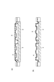
水圧転写法、フィルムインサート法においては、成形性、接着性、耐傷性、生産性等に課題がある。また、成形性等を改善した従来の真空加圧法においても、図10(a),(b)に示したように、加飾フィルムの浮き上がりが発生し、それに関連する製品不良が生じやすくなるといった問題がある。また、従来の真空加圧法では、深絞りの場合、形状追従性にやや問題があり、パーティングラインが見えるなど外観の問題もあった。
本発明は、上記問題を解決し、成形性、接着性、生産性等が良好で、且つ加飾フィルムの浮き上がりがない真空成形機を提供することを目的とする。
本発明の一側面に係る真空成形機は、上方に開口した下ボックスと下方に開口した上ボックスとによって密閉形成された成形空間内において、被着体の表面に加飾フィルムを密着させて成形する真空成形機であって、下ボックスには、被着体を載置収容する収容部が設置されており、上ボックスの下端部には、加飾フィルムの浮きを抑える冶具が設置されている。
また、上ボックスの下端部において、冶具が、個々の被着体間を区画するように、且つ被着体の周囲外方に位置するように設置されていてもよい。
また、冶具が、ワイヤ状、または、薄板状であってもよい。
また、ワイヤ状の冶具において、直径が3~5mmであり、ワイヤ張力が50~200Nであってもよい。
本発明の一側面により、成形性、接着性、生産性等が良好で、且つ加飾フィルムの浮き上がりがない真空成形機を提供することが可能となる。
本発明の一側面に係る真空成形機は、上方に開口した下ボックスと下方に開口した上ボックスとによって密閉形成された成形空間内において、被着体の表面に加飾フィルムを密着させて成形する真空成形機であって、下ボックスには、被着体を載置収容する収容部が設置されており、上ボックスの下端部には、加飾フィルムの浮きを抑える冶具が設置されている。
以下、本発明の一側面に係る真空成形機の実施形態について、図面を参照しながら詳細に説明する。
真空成形方法は、基本的に、互いに近接乃至離間する下ボックスと上ボックスとによって密閉の成形空間乃至開放状態が形成される本実施形態の真空成形機Mを用いて、被着体の表面に加飾フィルムを密着させて成形する。
なお、被着体とは、樹脂成形された成形体である。被着体は、例えば、自動車用のインスツルメントパネル及びコンソールボックス等として使用される。また、加飾フィルムとは、印刷、塗装、真空蒸着、着色等で加飾した、透明もしくは半透明の樹脂フィルムである。加飾フィルムの材質は特に限定されない。加飾フィルムの材質として、具体的にはアクリル系樹脂、ポリエステル系樹脂、ポリオレフィン系樹脂、ポリカーボネート系樹脂、フッ素樹脂等が挙げられる。
また、被着体の表面には、加飾フィルムとの密着性を向上させるため、プライマ処理、火炎処理等の密着性促進処理が行われることが好ましい。密着性促進処理としては、フレーム処理、コロナ処理、イトロ処理等の火炎処理が好ましく、特にフレーム処理が好ましい。
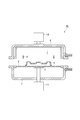
また、図1に示したように、本実施形態の真空成形機Mにおいて、下ボックス1には、被着体4を載置収容する収容部3が設置されており、上ボックス6内の下端部には、加飾フィルム5(図2参照)の浮きを抑える冶具8が設置されている。
図7及び図8は、本実施形態の真空成形機の上ボックスの下端部を示す斜視図である。上ボックス6の下端部9aには、図7に示すように、加飾フィルム5の浮きを抑えるワイヤ状の冶具8aが設置されている。或いは、上ボックス6の下端部9bには、図8に示すように、加飾フィルム5の浮きを抑える薄板状の冶具8bが設置されている。
図7、8に示すように、上ボックス6の下端部9a,9bにおいて、加飾フィルム5の浮きを抑える冶具8a,8bは、個々の被着体4間を区画するように、且つ被着体4の周囲外方に位置するように設置されている。「個々の被着体4間を区画するように」とは、下ボックス1内に設置した可動式のテーブル2上の収容部3に複数の被着体4が載置収容されている場合において、少なくとも隣接する二つの被着体4の間に加飾フィルム5の浮きを抑える冶具8が設置されていることである。
なお、冶具8は、被着体4の近傍であって、被着体4の周囲外方に位置するように設置されていることが好ましい。また、被着体4が四辺形の場合、冶具8は、少なくともその1辺の周囲外方の近傍にあればよく、2辺以上にあるのが好ましい。
加飾フィルム5の浮きを抑える冶具8は、加飾フィルム5の浮きを抑える機能を有していれば、材質、形状等は特に限定されない。当該冶具8は、ワイヤ状、または、薄板状であることが好ましい。ワイヤ状の冶具8aであれば、直径は3~5mmであり、材質はステンレスである。また、薄板状の冶具8bであれば、厚さは3~5mm、幅は20~50mmであり、材質はアルミ、またはステンレスである。
また、ワイヤ状の冶具8aにおいて、加飾フィルム5の反力を抑えるため、ワイヤ張力は、50~200Nである。ワイヤ張力が50N未満であれば、加飾フィルム5の浮きが発生するおそれがある。また、ワイヤ張力が200Nを超える場合、加飾フィルム5が必要以上に過度な延伸状態になり、加飾フィルム5にしわが発生するおそれがある。ワイヤ状の冶具8aにおいて、直径が3~5mmの範囲内であることにより、加飾フィルム5の反力が抑えられ、加飾フィルム5の浮きが発生しない。
図1に示したように、本実施形態の真空成形機Mにおいては、上ボックス6内にはヒーター7が組み込まれている。ヒーター7は、上ボックス6と下ボックス1とが接合された成形空間内で、加飾フィルム5を加熱する。
上ボックス6と下ボックス1とは、接合及び離反が可能とされている。すなわち上ボックス6には駆動装置10が設けられており、上ボックス6は、上昇及び下降が可能とされている。また、下ボックス1の内部にテーブル2が配設されており、テーブル2は駆動装置11により上昇及び下降が可能とされている。各駆動装置10,11として例えばエアーシリンダ、油圧シリンダ、サーボモータ等を用いることができる。また、下ボックス1内には真空回路が配管されている。上ボックス6内には真空回路及び圧空(圧縮空気)回路が配管されている。
本実施形態の真空成形機Mを使用した真空形成方法は、載置工程と、密閉工程と、加熱工程と、成形工程と、圧力調整工程と、圧力解除工程と、取出工程と、を有している。以下、本実施形態の真空成形機Mを使用した真空成形方法の各工程を説明する。
図1に示したように、載置工程では、下ボックス1内に設置した可動式のテーブル2上の収容部3に被着体4を載置収容する。なお、予め被着体4を収容した収容部3をテーブル2上に移動し載置してもよい。あるいは、テーブル2上に収容部3を載置し、それに被着体4を収容してもよい。
図2に示したように、密閉工程では、収容部3に被着体4を載置収容した可動式のテーブル2を下げた後、加飾フィルム5を境として成形空間を上下に仕切るように、加飾フィルム5を下ボックス1の上部に載置する。これにより、加飾フィルム5を境として成形空間を上下に仕切り、下部の成形空間内にテーブル2及び被着体4を密閉する。
その後、図3に示したように、加熱工程では、加飾フィルム5を加熱する。ここでは、上ボックス6を下げ、下ボックス1と密着させることにより、下部の成形空間内にテーブル2及び被着体4を密閉する。続いて、ヒーター7を起動し、加飾フィルム5を加熱する。さらに、下ボックス1及び上ボックス6の両方を、真空ポンプ(不図示)等を利用し、真空状態まで減圧する。なお、密閉状態とは、加飾フィルム5を、下ボックス1の上部に載置し、さらに下ボックス1と上ボックス6とを密着させた状態である。
図4に示したように、成形工程では、加熱工程によって加熱された加飾フィルム5の下方から、載置工程によって被着体4を載置したテーブル2を近接させて、被着体4の表面に加飾フィルム5を密着成形する。加熱された加飾フィルム5の温度が100~150℃になると、被着体4を載置したテーブル2が上昇し、被着体4の表面の一部に加飾フィルム5が接触する(被せられる)。その際、上ボックス6の下端部に設置された冶具8により、被着体4の周囲外方の加飾フィルム5の浮きが抑えられる。
図5に示したように、圧力調整工程では、密閉工程によって密閉した下部の成形空間内を上部の成形空間内に対して減圧させて、仕切られた成形空間に圧力差を発生させる。これにより、テーブル2上にセットした被着体4の表面近傍をその周囲よりも減圧環境とする。具体的には、図5に示したように、テーブル2と加飾フィルム5とを境にして、下部の成形空間内は減圧状態を維持し、上部の成形空間内は加圧または大気開放し、減圧状態を解除する。その際、上部の成形空間内は加圧状態或いは大気圧状態のいずれでもよい。また、加飾フィルム5の加熱は停止する。
成形空間に圧力差を発生させる際、加飾フィルム5の加熱を停止することによって、加熱による加飾フィルム5の過度の延伸状態が緩和される。これにより、加飾フィルム5が被着体4の形状に適度に追従するので、加飾フィルム5の浮きの要因となる加飾フィルム5のたるみが発生しなくなる。
なお、下部(下ボックス1)の成形空間内を上部(上ボックス6)の成形空間内に対して減圧させて、仕切られた成形空間に圧力差を発生させることが可能であれば、下部(下ボックス1)の成形空間内は減圧状態(真空状態)を維持し、上部(上ボックス)の成形空間内は大気開放せずに、減圧状態(真空状態)を緩和し、大気圧未満の状態としてもよい。
図5及び図9(b)に示したように、上部の成形空間(上ボックス6)内の真空を開放することにより、加飾フィルム5は被着体4に押し付けられてオーバーレイ(成形)される。なお、圧空タンク(不図示)により上部の成形空間(上ボックス6)内に圧縮空気を供給することにより(加圧状態)、さらに大きな力で加飾フィルム5を被着体4に密着させることもできる。
また、テーブル2上にセットした被着体4の表面近傍がその周囲よりも減圧環境となり、さらに、図4及び図9(a)に示したように、テーブル2が上昇する際、上ボックス6の下端部に設置された冶具8bにより、被着体4の周囲外方の加飾フィルム5の浮きが抑えられる。このため、被着体4の表面に加飾フィルム5が、追従し確実に密着する。特に、加飾フィルム5の浮きが抑えられるため、深絞りの場合でも、形状追従性に問題なく、また、加飾フィルム5の末端が確実に巻き込まれ、パーティングラインが見えないため、外観性も良好である。
本実施形態の真空成形機Mを使用する真空成形方法においては、圧力調整工程は、成形工程の後に行ってもよく、あるいは、成形工程と略同時に行ってもよい。圧力調整工程と、成形工程とを略同時行うことにより、加飾フィルム5が被着体4の表面に、一気に、均一に貼りつくので、外観上の不具合(しわ等)解消に効果があり、好ましい。
図6に示したように、圧力解除工程では、圧力調整工程によって発生した圧力差を解除し、取り出し工程では、圧力解除と共に成形品を取り出す。下部の成形空間内及び上部の成形空間内は、大気開放され、圧力差は解除される。その後、上ボックス6が上昇し、加飾フィルム5を有する被着体4(成形品)が取り出される。
1…下ボックス、2…テーブル、3…収容部、4…被着体、5…加飾フィルム、6…上ボックス、7…ヒーター、8,8a,8b…冶具、9a,9b…上ボックスの下端部、10,11…駆動装置、M…真空成形機。
Claims (4)
- 上方に開口した下ボックスと下方に開口した上ボックスとによって密閉形成された成形空間内において、被着体の表面に加飾フィルムを密着させて成形する真空成形機であって、
前記下ボックスには、前記被着体を載置収容する収容部が設置されており、
前記上ボックスの下端部には、前記加飾フィルムの浮きを抑える冶具が設置されている、真空成形機。 - 前記上ボックスの下端部において、前記冶具が、個々の前記被着体間を区画するように、且つ前記被着体の周囲外方に位置するように設置されている請求項1記載の真空成形機。
- 前記冶具が、ワイヤ状、または、薄板状である、請求項1または2に記載の真空成形機。
- ワイヤ状の前記冶具において、直径が3~5mmであり、ワイヤ張力が50~200Nである請求項3に記載の真空成形機。
Priority Applications (1)
| Application Number | Priority Date | Filing Date | Title |
|---|---|---|---|
| US15/029,129 US20160250799A1 (en) | 2013-10-22 | 2014-10-20 | Vacuum forming machine |
Applications Claiming Priority (4)
| Application Number | Priority Date | Filing Date | Title |
|---|---|---|---|
| JP2013219122 | 2013-10-22 | ||
| JP2013-219123 | 2013-10-22 | ||
| JP2013-219122 | 2013-10-22 | ||
| JP2013219123 | 2013-10-22 |
Publications (1)
| Publication Number | Publication Date |
|---|---|
| WO2015060264A1 true WO2015060264A1 (ja) | 2015-04-30 |
Family
ID=52992858
Family Applications (2)
| Application Number | Title | Priority Date | Filing Date |
|---|---|---|---|
| PCT/JP2014/077867 Ceased WO2015060263A1 (ja) | 2013-10-22 | 2014-10-20 | 真空成形方法 |
| PCT/JP2014/077868 Ceased WO2015060264A1 (ja) | 2013-10-22 | 2014-10-20 | 真空成形機 |
Family Applications Before (1)
| Application Number | Title | Priority Date | Filing Date |
|---|---|---|---|
| PCT/JP2014/077867 Ceased WO2015060263A1 (ja) | 2013-10-22 | 2014-10-20 | 真空成形方法 |
Country Status (2)
| Country | Link |
|---|---|
| US (2) | US20160250799A1 (ja) |
| WO (2) | WO2015060263A1 (ja) |
Families Citing this family (6)
| Publication number | Priority date | Publication date | Assignee | Title |
|---|---|---|---|---|
| GB2545469A (en) * | 2015-12-17 | 2017-06-21 | C & J Clark Int Ltd | Manufacturing articles of footwear |
| CN108908903A (zh) * | 2018-05-08 | 2018-11-30 | 滁州市精美家电设备有限责任公司 | 一种冰箱内胆真空成形模具 |
| JP7202076B2 (ja) * | 2018-05-15 | 2023-01-11 | トーホー工業株式会社 | 包装容器 |
| TWI684492B (zh) * | 2018-10-17 | 2020-02-11 | 閎暉實業股份有限公司 | 對位治具及使用其之模外裝飾方法 |
| FR3102117B1 (fr) * | 2019-10-21 | 2022-06-24 | Faurecia Interieur Ind | Procédé de réalisation d’un élément de garnissage comprenant un élément décoratif |
| JP2026503205A (ja) * | 2023-01-03 | 2026-01-28 | エーファウ・グループ・エー・タルナー・ゲーエムベーハー | 排気された加工室内で基板を加工する装置および方法 |
Citations (10)
| Publication number | Priority date | Publication date | Assignee | Title |
|---|---|---|---|---|
| JPS4943710B1 (ja) * | 1970-03-27 | 1974-11-22 | ||
| JPH07186274A (ja) * | 1993-12-27 | 1995-07-25 | Hitachi Chem Co Ltd | オレフィン系コア材表面への表皮材の貼着方法 |
| JPH1052858A (ja) * | 1996-08-12 | 1998-02-24 | Araco Corp | 被覆シートの基材表面への貼着方法 |
| JP2002079573A (ja) * | 2000-09-06 | 2002-03-19 | Fuse Shinku Kk | 真空成型装置 |
| JP2007264373A (ja) * | 2006-03-29 | 2007-10-11 | Toppan Printing Co Ltd | インモールド成形容器用ラベルおよびインモールド成形容器 |
| WO2009004821A1 (ja) * | 2007-07-03 | 2009-01-08 | Nippon Soda Co., Ltd. | ハードコート層を形成するための成形用シート |
| JP2012096403A (ja) * | 2010-10-29 | 2012-05-24 | Three M Innovative Properties Co | フィルム成型装置及びフィルム成型方法 |
| JP2012116094A (ja) * | 2010-11-30 | 2012-06-21 | Fuse Shinku Kk | 真空成型方法 |
| JP2013049878A (ja) * | 2011-08-30 | 2013-03-14 | Nissha Printing Co Ltd | 燃焼化学気相蒸着装置及び加飾品の製造方法 |
| JP2013052424A (ja) * | 2011-09-05 | 2013-03-21 | Mikado Technos Kk | 真空加熱接合装置及び真空加熱接合方法 |
Family Cites Families (2)
| Publication number | Priority date | Publication date | Assignee | Title |
|---|---|---|---|---|
| JPS4943710Y1 (ja) | 1968-12-19 | 1974-11-30 | ||
| MX341955B (es) * | 2010-04-15 | 2016-09-08 | 3M Innovative Properties Co | Articulos retrorreflectantes que incluyen areas opticamente activas y areas opticamente inactivas. |
-
2014
- 2014-10-20 US US15/029,129 patent/US20160250799A1/en not_active Abandoned
- 2014-10-20 WO PCT/JP2014/077867 patent/WO2015060263A1/ja not_active Ceased
- 2014-10-20 US US15/029,132 patent/US10173361B2/en active Active
- 2014-10-20 WO PCT/JP2014/077868 patent/WO2015060264A1/ja not_active Ceased
Patent Citations (10)
| Publication number | Priority date | Publication date | Assignee | Title |
|---|---|---|---|---|
| JPS4943710B1 (ja) * | 1970-03-27 | 1974-11-22 | ||
| JPH07186274A (ja) * | 1993-12-27 | 1995-07-25 | Hitachi Chem Co Ltd | オレフィン系コア材表面への表皮材の貼着方法 |
| JPH1052858A (ja) * | 1996-08-12 | 1998-02-24 | Araco Corp | 被覆シートの基材表面への貼着方法 |
| JP2002079573A (ja) * | 2000-09-06 | 2002-03-19 | Fuse Shinku Kk | 真空成型装置 |
| JP2007264373A (ja) * | 2006-03-29 | 2007-10-11 | Toppan Printing Co Ltd | インモールド成形容器用ラベルおよびインモールド成形容器 |
| WO2009004821A1 (ja) * | 2007-07-03 | 2009-01-08 | Nippon Soda Co., Ltd. | ハードコート層を形成するための成形用シート |
| JP2012096403A (ja) * | 2010-10-29 | 2012-05-24 | Three M Innovative Properties Co | フィルム成型装置及びフィルム成型方法 |
| JP2012116094A (ja) * | 2010-11-30 | 2012-06-21 | Fuse Shinku Kk | 真空成型方法 |
| JP2013049878A (ja) * | 2011-08-30 | 2013-03-14 | Nissha Printing Co Ltd | 燃焼化学気相蒸着装置及び加飾品の製造方法 |
| JP2013052424A (ja) * | 2011-09-05 | 2013-03-21 | Mikado Technos Kk | 真空加熱接合装置及び真空加熱接合方法 |
Also Published As
| Publication number | Publication date |
|---|---|
| WO2015060263A1 (ja) | 2015-04-30 |
| US20160250799A1 (en) | 2016-09-01 |
| US10173361B2 (en) | 2019-01-08 |
| US20160263811A1 (en) | 2016-09-15 |
Similar Documents
| Publication | Publication Date | Title |
|---|---|---|
| WO2015060264A1 (ja) | 真空成形機 | |
| JP5694641B2 (ja) | ラッピング立体成形体及びその製造方法 | |
| JP5781033B2 (ja) | 真空・加圧フィルム貼着装置及び真空・加圧フィルム貼着方法 | |
| TW201720624A (zh) | 熱成形裝置及熱成形方法 | |
| JP2012096403A5 (ja) | ||
| WO2011080850A1 (ja) | 熱板加熱による熱成形装置および熱成形方法 | |
| CN107921695B (zh) | 粘附体的表面保护方法以及表面装饰方法 | |
| US7703392B2 (en) | Pressure based method and apparatus for applying a decoration onto an object | |
| US9511541B2 (en) | Forming apparatus and forming method | |
| JP5957131B1 (ja) | 熱成形装置および熱成形方法 | |
| JP6871107B2 (ja) | 熱成形装置及び熱成形方法 | |
| JP4918175B1 (ja) | 成形装置および成形方法 | |
| JP5791842B1 (ja) | 熱成形装置及び熱成形方法 | |
| JP4972219B1 (ja) | 成形装置および成形方法 | |
| JP2017065221A (ja) | フィルム被覆部品の製造装置及び製造方法 | |
| CN100348409C (zh) | 装饰用板、成形品、机动车辆及成形品的制造方法 | |
| JP2015107638A (ja) | 真空成形機 | |
| JP2015107639A (ja) | 真空成形方法 | |
| US20220169069A1 (en) | Hot stamping apparatus and hot stamping method | |
| WO2017099051A1 (ja) | インモールド射出成形金型装置及び樹脂成形品製造方法 | |
| JP2016087960A (ja) | フィルム加飾部品の製造方法及びフィルム加飾部品 | |
| JP2016078278A (ja) | 自動車内装品の製造方法及び製造装置 | |
| JP6769781B2 (ja) | 加飾成形装置、加飾成形品の製造方法及び成形治具 | |
| JP2016093905A (ja) | フィルム加飾部品の製造方法 | |
| JP2008126428A (ja) | 表皮の貼着方法並びに貼着装置 |
Legal Events
| Date | Code | Title | Description |
|---|---|---|---|
| 121 | Ep: the epo has been informed by wipo that ep was designated in this application |
Ref document number: 14856287 Country of ref document: EP Kind code of ref document: A1 |
|
| WWE | Wipo information: entry into national phase |
Ref document number: 15029129 Country of ref document: US |
|
| NENP | Non-entry into the national phase |
Ref country code: DE |
|
| 122 | Ep: pct application non-entry in european phase |
Ref document number: 14856287 Country of ref document: EP Kind code of ref document: A1 |