WO2015060060A1 - インクジェット記録装置及び媒体搬送方法 - Google Patents
インクジェット記録装置及び媒体搬送方法 Download PDFInfo
- Publication number
- WO2015060060A1 WO2015060060A1 PCT/JP2014/075410 JP2014075410W WO2015060060A1 WO 2015060060 A1 WO2015060060 A1 WO 2015060060A1 JP 2014075410 W JP2014075410 W JP 2014075410W WO 2015060060 A1 WO2015060060 A1 WO 2015060060A1
- Authority
- WO
- WIPO (PCT)
- Prior art keywords
- medium
- reversing
- paper
- unit
- cylinder
- Prior art date
- Legal status (The legal status is an assumption and is not a legal conclusion. Google has not performed a legal analysis and makes no representation as to the accuracy of the status listed.)
- Ceased
Links
Images


Classifications
-
- B—PERFORMING OPERATIONS; TRANSPORTING
- B65—CONVEYING; PACKING; STORING; HANDLING THIN OR FILAMENTARY MATERIAL
- B65H—HANDLING THIN OR FILAMENTARY MATERIAL, e.g. SHEETS, WEBS, CABLES
- B65H5/00—Feeding articles separated from piles; Feeding articles to machines
- B65H5/08—Feeding articles separated from piles; Feeding articles to machines by grippers, e.g. suction grippers
- B65H5/12—Revolving grippers, e.g. mounted on arms, frames or cylinders
-
- B—PERFORMING OPERATIONS; TRANSPORTING
- B41—PRINTING; LINING MACHINES; TYPEWRITERS; STAMPS
- B41J—TYPEWRITERS; SELECTIVE PRINTING MECHANISMS, i.e. MECHANISMS PRINTING OTHERWISE THAN FROM A FORME; CORRECTION OF TYPOGRAPHICAL ERRORS
- B41J2/00—Typewriters or selective printing mechanisms characterised by the printing or marking process for which they are designed
- B41J2/005—Typewriters or selective printing mechanisms characterised by the printing or marking process for which they are designed characterised by bringing liquid or particles selectively into contact with a printing material
- B41J2/01—Ink jet
- B41J2/135—Nozzles
- B41J2/14—Structure thereof only for on-demand ink jet heads
- B41J2/14201—Structure of print heads with piezoelectric elements
- B41J2/14233—Structure of print heads with piezoelectric elements of film type, deformed by bending and disposed on a diaphragm
-
- B—PERFORMING OPERATIONS; TRANSPORTING
- B41—PRINTING; LINING MACHINES; TYPEWRITERS; STAMPS
- B41J—TYPEWRITERS; SELECTIVE PRINTING MECHANISMS, i.e. MECHANISMS PRINTING OTHERWISE THAN FROM A FORME; CORRECTION OF TYPOGRAPHICAL ERRORS
- B41J2/00—Typewriters or selective printing mechanisms characterised by the printing or marking process for which they are designed
- B41J2/005—Typewriters or selective printing mechanisms characterised by the printing or marking process for which they are designed characterised by bringing liquid or particles selectively into contact with a printing material
- B41J2/01—Ink jet
- B41J2/135—Nozzles
- B41J2/145—Arrangement thereof
- B41J2/155—Arrangement thereof for line printing
-
- B—PERFORMING OPERATIONS; TRANSPORTING
- B41—PRINTING; LINING MACHINES; TYPEWRITERS; STAMPS
- B41J—TYPEWRITERS; SELECTIVE PRINTING MECHANISMS, i.e. MECHANISMS PRINTING OTHERWISE THAN FROM A FORME; CORRECTION OF TYPOGRAPHICAL ERRORS
- B41J3/00—Typewriters or selective printing or marking mechanisms characterised by the purpose for which they are constructed
- B41J3/60—Typewriters or selective printing or marking mechanisms characterised by the purpose for which they are constructed for printing on both faces of the printing material
-
- B—PERFORMING OPERATIONS; TRANSPORTING
- B65—CONVEYING; PACKING; STORING; HANDLING THIN OR FILAMENTARY MATERIAL
- B65H—HANDLING THIN OR FILAMENTARY MATERIAL, e.g. SHEETS, WEBS, CABLES
- B65H85/00—Recirculating articles, i.e. feeding each article to, and delivering it from, the same machine work-station more than once
-
- B—PERFORMING OPERATIONS; TRANSPORTING
- B41—PRINTING; LINING MACHINES; TYPEWRITERS; STAMPS
- B41J—TYPEWRITERS; SELECTIVE PRINTING MECHANISMS, i.e. MECHANISMS PRINTING OTHERWISE THAN FROM A FORME; CORRECTION OF TYPOGRAPHICAL ERRORS
- B41J2/00—Typewriters or selective printing mechanisms characterised by the printing or marking process for which they are designed
- B41J2/005—Typewriters or selective printing mechanisms characterised by the printing or marking process for which they are designed characterised by bringing liquid or particles selectively into contact with a printing material
- B41J2/01—Ink jet
- B41J2/135—Nozzles
- B41J2/14—Structure thereof only for on-demand ink jet heads
- B41J2/14201—Structure of print heads with piezoelectric elements
- B41J2/14233—Structure of print heads with piezoelectric elements of film type, deformed by bending and disposed on a diaphragm
- B41J2002/14241—Structure of print heads with piezoelectric elements of film type, deformed by bending and disposed on a diaphragm having a cover around the piezoelectric thin film element
-
- B—PERFORMING OPERATIONS; TRANSPORTING
- B41—PRINTING; LINING MACHINES; TYPEWRITERS; STAMPS
- B41J—TYPEWRITERS; SELECTIVE PRINTING MECHANISMS, i.e. MECHANISMS PRINTING OTHERWISE THAN FROM A FORME; CORRECTION OF TYPOGRAPHICAL ERRORS
- B41J2/00—Typewriters or selective printing mechanisms characterised by the printing or marking process for which they are designed
- B41J2/005—Typewriters or selective printing mechanisms characterised by the printing or marking process for which they are designed characterised by bringing liquid or particles selectively into contact with a printing material
- B41J2/01—Ink jet
- B41J2/135—Nozzles
- B41J2/14—Structure thereof only for on-demand ink jet heads
- B41J2002/14459—Matrix arrangement of the pressure chambers
-
- B—PERFORMING OPERATIONS; TRANSPORTING
- B41—PRINTING; LINING MACHINES; TYPEWRITERS; STAMPS
- B41J—TYPEWRITERS; SELECTIVE PRINTING MECHANISMS, i.e. MECHANISMS PRINTING OTHERWISE THAN FROM A FORME; CORRECTION OF TYPOGRAPHICAL ERRORS
- B41J2/00—Typewriters or selective printing mechanisms characterised by the printing or marking process for which they are designed
- B41J2/005—Typewriters or selective printing mechanisms characterised by the printing or marking process for which they are designed characterised by bringing liquid or particles selectively into contact with a printing material
- B41J2/01—Ink jet
- B41J2/135—Nozzles
- B41J2/14—Structure thereof only for on-demand ink jet heads
- B41J2002/14491—Electrical connection
-
- B—PERFORMING OPERATIONS; TRANSPORTING
- B41—PRINTING; LINING MACHINES; TYPEWRITERS; STAMPS
- B41J—TYPEWRITERS; SELECTIVE PRINTING MECHANISMS, i.e. MECHANISMS PRINTING OTHERWISE THAN FROM A FORME; CORRECTION OF TYPOGRAPHICAL ERRORS
- B41J2202/00—Embodiments of or processes related to ink-jet or thermal heads
- B41J2202/01—Embodiments of or processes related to ink-jet heads
- B41J2202/12—Embodiments of or processes related to ink-jet heads with ink circulating through the whole print head
-
- B—PERFORMING OPERATIONS; TRANSPORTING
- B41—PRINTING; LINING MACHINES; TYPEWRITERS; STAMPS
- B41J—TYPEWRITERS; SELECTIVE PRINTING MECHANISMS, i.e. MECHANISMS PRINTING OTHERWISE THAN FROM A FORME; CORRECTION OF TYPOGRAPHICAL ERRORS
- B41J2202/00—Embodiments of or processes related to ink-jet or thermal heads
- B41J2202/01—Embodiments of or processes related to ink-jet heads
- B41J2202/20—Modules
Definitions
- the present invention relates to an ink jet recording apparatus and a medium conveying method, and more particularly to a medium reversal technique and a medium conveying technique in an ink jet recording apparatus.
- An ink jet recording apparatus is known as a general-purpose image forming apparatus.
- Inkjet recording devices are water-based inks (inks in which coloring materials such as dyes and pigments are dissolved or dispersed in water and water-soluble solvents) on general-purpose printing paper (paper such as coated paper).
- paper such as coated paper.
- Patent Document 1 describes an ink jet recording apparatus including a conveying unit in which irregularities of a predetermined pattern are formed on an adsorption holding surface for adsorbing and holding a sheet, and suction holes are formed in the depressions.
- the cockle generated on the paper is absorbed by the concave portion, and the paper is brought into close contact with the suction holding surface.
- Patent Document 2 describes an ink jet recording apparatus including a conveying unit in which a plurality of ribs are arranged on a support surface of a sheet.
- the ink jet recording apparatus described in Japanese Patent Laid-Open No. 2004-228561 prevents the sheet from floating during sheet conveyance by optimizing the interval and / or height of the ribs.
- a printing apparatus that includes a cylinder having a gripper and grips and conveys paper using the gripper, when the paper is wound up in a state of being lifted with respect to the cylinder, the paper holding position is shifted when the paper is changed over. There is a problem that it ends up.
- Patent Document 3 discloses a double-sided printing machine provided with a paper reversing mechanism for reversing the front and back of a paper by changing the paper bottom of the paper conveyed by the transfer cylinder upstream of the reversing cylinder in the paper conveying direction with a gripper of the reversing cylinder. Is described.
- the printing machine described in Patent Document 3 includes an air supply unit that blows air toward a paper transfer portion in order to tightly wind the paper around the second transfer cylinder.
- Patent Documents 1 and 2 are effective in preventing the sheet from floating in the form in which the sheet is sucked and held, in the form in which a part of the sheet is gripped and conveyed, It is difficult to prevent floating of a portion where the paper is not gripped.
- the amount of water that adheres to the sheet is larger than that of an image forming apparatus of another method such as an offset method. Deformation becomes large.
- Inkjet image formation has a configuration in which air is blown toward a paper transfer portion from the first transfer cylinder to the second transfer cylinder described in Patent Document 3 and a paper is pulled in a direction opposite to the conveyance direction using a paper guide. Even if it is applied to the paper, it is difficult to make the paper tightly contact the second transfer cylinder, considering that the deformation of the paper after the image formation on the surface is larger in the ink jet method than in the offset printing machine or the like.
- the trailing edge of the paper that is not gripped will float, the slack in the width direction, etc., and the position of the gripping position will shift when the paper is turned over by the reversing cylinder. In other words, wrinkles (sag) of the grip position occur.
- the present invention has been made in view of such circumstances, and prevents the occurrence of misalignment, wrinkles and the like of the gripping position when changing the medium due to deformation of the medium, and conveys the medium with high accuracy. It is an object of the present invention to provide an ink jet recording apparatus and a medium conveying method that make it possible.
- An ink jet recording apparatus for achieving the above object includes a medium supply unit for supplying a medium and a gripping unit for gripping the medium supplied from the medium supply unit.
- the first unit grips and conveys the medium by the gripping unit.
- Medium reversing means for reversing the first surface and the second surface of the first surface, and gripping means for gripping the medium obtained by reversing the first surface and the second surface by the medium reversing means.
- a second medium transporting means for gripping and transporting the medium whose surface is reversed by the gripping means, and the medium reversing means includes a gripping means for gripping the medium delivered from the first medium transporting means.
- the medium in which the two surfaces are reversed and the first surface and the second surface are reversed is delivered to the second medium conveying means, and the pressing cylinder has an outer peripheral surface on which an elastic layer is formed.
- the elastic layer is brought into contact with the medium gripped by the gripping means of the reverse transfer cylinder, and a pressing force is applied to the medium gripped by the gripping means of the reverse transfer cylinder.
- the elastic layer formed on the outer peripheral surface of the pressing cylinder is brought into contact with the medium gripped by the gripping means of the reverse transfer cylinder and the medium is pressed against the outer peripheral surface of the reverse transfer cylinder, the medium is brought into close contact with the outer peripheral surface of the reverse transfer cylinder.
- the end of the reversing transfer cylinder is gripped by the gripping means of the reversing cylinder, the other end of the medium is prevented from being lifted or wrinkled. Therefore, the grip position shift when the medium is replaced is prevented, and the occurrence of wrinkles or the like of the medium gripped and transported by the gripping means is prevented. Further, by bringing the elastic layer into contact with the medium, the medium is prevented from being damaged when the medium is brought into close contact with the reversing transfer cylinder.
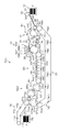
- FIG. 1 is an overall configuration diagram of an ink jet recording apparatus according to an embodiment of the present invention.
- 1 is a block diagram showing the configuration of a control system of the ink jet recording apparatus shown in FIG. 1 is a configuration diagram of an ink jet head provided in the ink jet recording apparatus shown in FIG.
- the perspective view which shows the structural example of the head module with which the inkjet head shown in FIG. 3 is equipped.
- FIG. 1 Development view showing an example of the structure of the outer peripheral surface (paper holding surface) of the reverse transfer cylinder
- the perspective view which expanded a part of outer peripheral surface of the inversion transfer cylinder shown in FIG. 1 is an overall configuration diagram showing a modification of the ink jet recording apparatus shown in FIG.
- FIG. 1 is an overall configuration diagram of an ink jet recording apparatus according to a first embodiment of the present invention.
- the ink jet recording apparatus 10 shown in FIG. 1 uses a water-based ink (ink obtained by dissolving or decomposing a coloring material such as a dye or a pigment in water and a solvent soluble in water) on a sheet of paper P (medium).
- a water-based ink obtained by dissolving or decomposing a coloring material such as a dye or a pigment in water and a solvent soluble in water
- This is an ink jet recording apparatus that records an image by a method.
- the ink jet recording apparatus 10 mainly includes a paper feeding unit 12 (medium supply unit) that feeds paper P, and a precoat unit that applies processing liquid to the front surface (or back surface) of the paper P fed from the paper feeding unit 12. 14, a processing liquid drying processing unit 16 that performs a drying process on the paper P to which the processing liquid has been applied by the precoat unit 14, and a front surface (or back surface) of the paper P that has been subjected to the drying processing by the processing liquid drying processing unit 16.
- An image forming unit 18 (image forming unit) that records an image by an ink jet method using water-based ink, and a drying fixing unit 20 (drying unit) that performs a drying process on the paper P on which the image is recorded by the image forming unit 18;
- Paper reversing unit 22 paper reversing means
- Transport unit 24 Second Constituted the body conveying means
- the paper feed unit 12 mainly includes a paper feed base 30, a soccer device 32, a paper feed roller pair 34, a feeder board 36, and a paper feed drum 40, and the paper stacked on the paper feed base 30. P is fed one by one to the precoat unit 14.
- the paper P stacked on the paper feed tray 30 is pulled up one by one in order from the top by the soccer device 32 and fed to the paper feed roller pair 34 (between the pair of upper and lower rollers 34A and 34B).
- the paper P fed to the paper feed roller pair 34 is fed forward by a pair of upper and lower rollers 34A and 34B and placed on the feeder board 36.
- the paper P placed on the feeder board 36 is delivered to the paper supply drum 40.
- the front end portion is gripped (gripped) by the gripper (grip means) 40 ⁇ / b> A of the paper feed drum 40 and conveyed to the precoat portion 14.
- the precoat unit 14 mainly applies a treatment liquid application drum 42 (an example of a first medium conveyance unit) that conveys the paper P and a process that applies a predetermined treatment liquid to the surface of the paper P that is conveyed by the treatment liquid application drum 42. And a liquid application unit 44 for applying (applying) the processing liquid to the surface of the paper P.
- a treatment liquid application drum 42 an example of a first medium conveyance unit
- a process that applies a predetermined treatment liquid to the surface of the paper P that is conveyed by the treatment liquid application drum 42.
- a liquid application unit 44 for applying (applying) the processing liquid to the surface of the paper P.
- the processing liquid applied to the surface of the paper P is applied with a processing liquid having a function of aggregating the color material in the water-based ink ejected onto the paper P in the subsequent image forming unit 18.
- the paper P transferred from the paper supply drum 40 of the paper supply unit 12 is transferred to the treatment liquid application drum 42.
- the treatment liquid application drum 42 conveys the paper P wrapped around the outer peripheral surface by rotating the paper P with a gripper (gripping means) 42 ⁇ / b> A.
- the processing liquid is applied to the surface of the paper P by bringing the application roller 44A, to which the processing liquid weighed by the metering roller 44C from the processing liquid tray 44B into a certain amount, is pressed and brought into contact with the surface of the paper P.
- coats a process liquid is not limited to roller application
- the processing liquid drying processing unit 16 mainly includes a processing liquid drying processing drum 46 (a component of the first medium transporting unit) that transports the paper P, a paper transport guide 48 that supports (guides) the back surface of the paper P, and processing.
- a processing liquid drying processing unit 50 that blows hot air on the surface of the paper P conveyed by the liquid drying processing drum 46, and dries the paper P with the processing liquid applied to the surface. Apply.
- the leading edge of the paper P delivered from the treatment liquid application drum 42 of the precoat unit 14 to the treatment liquid drying treatment drum 46 is gripped by a gripper (gripping means) 46A provided in the treatment liquid drying treatment drum 46.
- the back surface of the paper P is supported by the paper transport guide 48 with the front surface (the surface coated with the treatment liquid) facing inward.
- the paper P is conveyed by rotating the processing liquid drying processing drum 46.
- the image forming unit 18 mainly includes an image forming drum 52 (an example of a first medium transport unit, an image forming transport unit) that transports the paper P, and C (cyan), M (magenta), and Y (yellow) on the paper P. , K (black) ink-jet heads 56C, 56M, 56Y, and 56K that discharge ink droplets of each color, and an in-line sensor 58 that reads an image recorded on the paper P.
- an image forming drum 52 an example of a first medium transport unit, an image forming transport unit
- C cyan
- M magenta
- Y yellow
- K (black) ink-jet heads 56C, 56M, 56Y, and 56K that discharge ink droplets of each color
- an in-line sensor 58 that reads an image recorded on the paper P.
- a paper pressing roller that presses the paper P conveyed by the image forming drum 52 and closely contacts the outer peripheral surface of the image forming drum 52 may be provided between the delivery position of the paper P and the inkjet head 56C. .
- a color image is drawn on the surface of the paper P by ejecting ink droplets of C, M, Y, and K colors on the surface of the paper P on which the treatment liquid layer is formed.
- An aspect including a mist filter that captures ink mist and a drum cooling unit that cools the image forming drum 52 is also preferable.
- the ink jet head applied to this example includes a piezoelectric system (see FIG. 6) that ejects ink by utilizing the flexural deformation of a piezoelectric element, and a thermal system that ejects ink by generating a film boiling phenomenon by heating the ink.
- Various discharge methods such as an electrostatic method (not shown) in which charged ink is landed on a recording medium by electrostatic force (not shown) can be applied.
- a line-type head in which nozzles are formed over a length corresponding to the entire width of the sheet P (the total length in the main scanning direction orthogonal to the relative movement direction of the sheet P) is applied to the inkjet head applied to this example. (See FIG. 3).
- serial image formation it is also possible to apply serial image formation.
- Serial image formation includes an inkjet head in which nozzle rows are arranged in the conveyance direction of the paper P, and scanning of the inkjet head in the width direction of the paper P (direction perpendicular to the conveyance direction of the paper P). And recording is performed by intermittently repeating the conveyance of the paper P.
- the term “perpendicular” in this specification is not only an aspect that intersects at 90 °, but also an aspect that intersects at 90 ° among the aspects that intersect less than 90 ° or more than 90 °. It is assumed that “substantially orthogonal” that exhibits the above-described effects is included.
- the leading end of the paper P delivered from the processing liquid drying processing drum 46 of the processing liquid drying processing unit 16 to the image forming drum 52 is gripped by a gripper (gripping means) 52 ⁇ / b> A provided in the image forming drum 52.
- the sheet P can be brought into close contact with the outer peripheral surface of the image forming drum 52 by passing the sheet P under the sheet pressing roller.
- the sheet P brought into close contact with the outer peripheral surface of the image forming drum 52 is sucked by a suction pressure generated in a suction hole (not shown) formed in the outer peripheral surface of the image forming drum 52, and the outer peripheral surface of the image forming drum 52. Is sucked in.
- the ink deposited on the paper P reacts with the treatment liquid layer (ink aggregation layer) formed on the paper P, and is fixed on the surface of the paper P without causing feathering or bleeding. A quality image is formed.
- Image reading by the in-line sensor 58 is performed as necessary, and image defects (image abnormality) such as ejection failure (ejection abnormality) and density unevenness are inspected from the image reading data.
- image defects image abnormality
- ejection failure ejection abnormality
- density unevenness are inspected from the image reading data.
- the sheet P that has passed through the reading area of the in-line sensor 58 is transferred to the drying and fixing unit 20 (post-processing means after image formation) after the suction is released.
- the dry fixing unit 20 includes a dry fixing unit 68 that performs a drying process and a fixing process on the paper P transported by the chain gripper 64 (a component of the first medium transport unit, the post-processing transport unit). Then, the paper P after image formation is subjected to a drying process and a fixing process, the liquid component remaining on the surface of the paper P is removed, and the image is fixed on the paper P.
- the drying and fixing unit 68 there may be mentioned an aspect including a heat source such as a halogen heater or an infrared (IR) heater, and a fan that blows air (gas, fluid) heated by the heat source onto the paper P.
- a heat source such as a halogen heater or an infrared (IR) heater
- IR infrared
- a cooling device for cooling the paper P after the drying process and the fixing process may be provided.
- the drying and fixing unit 68 is provided with an ultraviolet light source, and irradiation with ultraviolet rays (active light) is performed as a fixing process. Is done.
- the leading edge of the paper P delivered from the image forming drum 52 of the image forming unit 18 to the chain gripper 64 is gripped by a gripper (gripping means) 64D provided in the chain gripper 64.
- the chain gripper 64 has a structure in which a pair of endless chains 64C are wound around the first sprocket 64A and the second sprocket 64B.
- the chain gripper 64 has a plurality of grippers (grip means) 64D arranged along the width direction of the paper P, and a group of grippers (grip means) 64D arranged along the width direction of the paper P Are arranged along the conveying direction (the moving direction of the chain 64C).
- the gripper (gripping means) 64D grips the paper P by sandwiching the leading end of the paper P between a nail and a claw base (both not shown).
- grippers (gripping means) other than the gripper (gripping means) 64D also have a similar structure for gripping the paper P by inserting the end of the paper P between the claws and the claw base.
- the rear end of the paper P conveyed by the chain gripper 64 (the back surface of the paper P on which no image is formed) is a paper on a guide plate (not shown) arranged at a certain distance from the chain gripper 64. It is sucked and held on the holding surface.
- the drying and fixing unit 20 includes a transfer cylinder 70 that transfers the paper P that has been subjected to the drying process and the fixing process to the subsequent sheet reversing unit 22.
- the transfer cylinder 70 includes a gripper (grip means) 70A for gripping the paper P, grips the paper P conveyed by the chain gripper 64, rotates counterclockwise in FIG. 1, and moves the paper P along the rotation path. Transport.
- the transfer cylinder 70 of the drying and fixing unit 20 has a structure in which grippers (gripping means) 70A are arranged at two positions whose rotation angles are shifted by 180 °.
- the chain gripper 64 is exemplified as means for transporting the paper P in the dry fixing unit 20, but the means for transporting the paper P in the dry fixing unit 20 is not limited to the chain gripper 64.
- an aspect including a pressure drum provided with a gripper (gripping means) and a transfer cylinder (a plurality of pressure drums and a plurality of transfer cylinders along the transport direction of the paper P) can also be arranged). It is also possible to apply a conveyance form such as a conveyance belt provided with a gripper (gripping means). Further, a member for adjusting the conveyance path of the paper P such as a transfer cylinder is appropriately provided at the delivery position of the paper P with the image forming unit 18 and the delivery position of the paper P with the paper reversing unit 22.
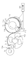
- the sheet reversing unit 22 includes a pressing cylinder 71, a reversing transfer cylinder 72, and a reversing cylinder 73 (components of switching means), which are arranged in the above order from the upstream side to the downstream side in the conveyance direction of the sheet P. Has been.
- the paper reversing unit 22 functions as means for reversing the front and back surfaces of the paper P, and switches means for switching the transport path of the paper P for switching whether the paper P is sent to the stacking unit 26 or sent to the reversing transport unit 24. Function as.
- the surface on which an image is formed when an image is formed on only one side of the paper P and the surface on which an image is formed when an image is formed on both sides are referred to as “surface” for convenience.
- (First surface) and the surface on which the image is formed after the image is formed on both surfaces is referred to as“ back surface (second surface) ”for convenience.
- the sheet P conveyed by the chain gripper 64 and the transfer cylinder 70 is transferred to the pressing cylinder 71 of the sheet reversing unit 22.
- the paper P delivered to the pressing cylinder 71 is sent to the inversion cylinder 73 via the inversion transfer cylinder 72.
- the paper P conveyed by the pressing cylinder 71 is gripped by the gripper (gripping means) 71A of the pressing cylinder 71, and the paper P conveyed by the reverse transfer cylinder 72 is gripped by the gripper (gripping means) 72A of the reverse transfer cylinder 72. Is done.
- the pressing cylinder 71 functions as means for applying a pressing force that presses the paper P against the outer peripheral surface of the reverse transfer cylinder 72 when the paper P is transferred to the reverse transfer cylinder 72.
- the paper P is pressed against the outer peripheral surface of the reverse transfer cylinder 72, and the paper P is brought into close contact with the outer peripheral surface of the reverse transfer cylinder 72.
- the outer peripheral surface of the pressing cylinder 71 is formed by an elastic layer (not shown in FIG. 1, but shown by reference numeral 71B in FIG. 7), and the elastic layer is brought into contact with the paper P so that the back surface of the paper P (elastic layer) (The surface opposite to the contact surface) is closely attached to the outer peripheral surface of the reverse transfer cylinder 72 (details will be described later).
- the length of the portion of the reverse transfer cylinder 72 that supports the back surface of the paper P in the transport direction of the paper P is less than the length in the transport direction of the paper P.
- the other end of the paper P is positioned upstream of the rear end of the portion of the reverse transfer cylinder 72 that supports the back surface of the paper P, so that the front and back surfaces of the paper P are reversed.
- the gripper (grip means) 73A of the reversing cylinder 73 can grip the other end of the paper P.
- the reversing cylinder 73 has a function of reversing the front and back surfaces of the paper P.
- a gripper (gripping means) 73A provided in the reversing cylinder 73 is configured to be capable of turning 180 ° around a rotation axis parallel to the rotation axis of the reversing cylinder 73 (see FIG. 7).
- the gripper (gripping means) 73A of the reversing cylinder 73 is directed to the upstream side in the rotation direction of the reversing cylinder 73 (illustrated using a solid line in FIG. 7).
- the gripper (gripping means) 73A of the reversing cylinder 73 is gripped by the gripper (gripping means) 73A of the reversing cylinder 73, and the gripping of the gripper (gripping means) 72A of the reversing transfer cylinder 72 is released.
- the paper P gripped by the gripper (grip means) 73A of the reversing cylinder 73 is transferred to the transfer cylinder 74 without reversing the front and back surfaces.
- the paper P delivered to the transfer cylinder 74 is gripped and conveyed by a gripper (gripping means) 74A. Further, the paper P conveyed by the transfer cylinder 74 is transferred to the chain gripper 77 of the stacking unit 26.
- the gripper (gripping means) 73A of the reversing cylinder 73 is on the downstream side in the rotation direction of the reversing cylinder 73. Directed (illustrated using dashed lines in FIG. 7).
- the other end of the paper P is gripped by a gripper (gripping means) 73A of the reversing cylinder 73, and the gripping of the gripper (gripping means) 72A of the reversing transfer cylinder 72 is released, so that the paper P is replaced. Further, the reversing cylinder 73 rotates in the clockwise direction in FIG. 1 and conveys the paper P while turning the gripper (gripping means) 73A by 180 ° to reverse the front and back surfaces of the paper P. Then, the paper P with the front and back reversed is delivered to the chain gripper 78 of the reverse conveyance unit 24.
- the reversing cylinder 73 functions as means for switching the conveyance path of the paper P so that the paper P with the front and back reversed is delivered to the reversal conveyance unit 24 and the paper P with the front and back not reversed is delivered to the stacking unit 26. To do. Details of the sheet reversing unit 22 will be described later.
- the reverse conveyance unit 24 is a unit that conveys the paper P with the front and back reversed in the case of duplex printing to the paper supply unit 12.
- the reverse conveying unit 24 includes a chain gripper 78 having a structure in which a pair of endless chains 78C are wound around the sprockets 78A and 78B.
- the chain gripper 78 can apply the same configuration as the chain gripper 64 of the processing liquid drying processing unit 16. Here, a detailed description of the configuration of the chain gripper 78 is omitted.
- the paper P gripped by the chain gripper 78 (gripper 78D) of the reversing conveyance unit 24 is transferred to the paper supply drum 40 (gripper 40A) of the paper supply unit 12 and sent to the image forming unit 18, and then the back side image. Formation is performed.
- the stacking unit 26 that collects the sheets P on which a series of image forming processes has been performed includes a paper discharge tray 76 (stocker) that stacks and collects the sheets P, and a chain gripper 77 that grips and conveys the sheets P.
- the chain gripper 77 can have the same configuration as the chain gripper 64 of the processing liquid drying processing unit 16 and the chain gripper 78 of the stacking unit 26. Here, a detailed description of the configuration of the chain gripper 77 is omitted.
- the chain gripper 77 (gripper 77D) releases the paper P on the paper discharge tray 76 and stacks the paper P on the paper discharge tray 76.
- the paper discharge tray 76 stacks and collects the paper P released from the chain gripper 77.
- the paper discharge tray 76 is provided with a sheet pad (not shown) (front sheet pad, rear sheet pad, horizontal sheet pad, etc.) so that the sheets P are stacked in an orderly manner.
- the paper discharge tray 76 is provided so as to be lifted and lowered by a paper discharge tray lifting / lowering device (not shown).
- the discharge platform lifting device is controlled in conjunction with the increase / decrease of the paper P stacked on the paper discharge tray 76 so that the uppermost paper P is always positioned at a certain height.
- the paper table 76 is moved up and down.
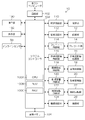
- FIG. 2 is a block diagram showing a schematic configuration of a control system of the inkjet recording apparatus 10 shown in FIG.
- the inkjet recording apparatus 10 includes a system controller 100, a communication unit 102, an image memory 104, a conveyance control unit 110, a paper feed control unit 112, a precoat control unit 114, a processing liquid drying control unit 116, and an image formation.
- a control unit 118, a drying and fixing control unit 120, a paper reversal control unit 122, an accumulation control unit 124, an operation unit 130, a display unit 132, and the like are provided.
- the system controller 100 functions as a control unit that performs overall control of each unit of the inkjet recording apparatus 10 and also functions as a calculation unit that performs various calculation processes.
- the system controller 100 includes a CPU (Central Processing Unit) 100A, a ROM (Read Only Memory) 100B, and a RAM (Random Access Memory) 100C.
- CPU Central Processing Unit
- ROM Read Only Memory
- RAM Random Access Memory
- the system controller 100 also functions as a memory controller that controls writing of data to the memories such as the ROM 100B, the RAM 100C, and the image memory 104 and reading of data from these memories.
- FIG 2 illustrates an example in which the memory such as the ROM 100B and the RAM 100C is built in the system controller 100, but the memory such as the ROM 100B and the RAM 100C may be provided outside the system controller 100.
- the communication unit 102 includes a required communication interface and transmits / receives data to / from a host computer connected to the communication interface.
- the image memory 104 functions as a temporary storage unit for various data including image data, and data is read and written through the system controller 100. Image data captured from the host computer via the communication unit 102 is temporarily stored in the image memory 104.
- the conveyance control unit 110 controls the operation of the conveyance system of the paper P in the inkjet recording apparatus 10 (conveyance of the paper P from the paper feeding unit 12 to the stacking unit 26 and conveyance of the paper P of the reverse conveyance unit 24).
- the conveyance system includes a paper supply drum 40 in the paper supply unit 12 illustrated in FIG. 1, a processing liquid application drum 42 in the precoat unit 14, a processing liquid drying processing drum 46 in the processing liquid drying processing unit 16, and an image in the image forming unit 18.
- the forming drum 52, the chain gripper 64 of the drying and fixing unit 20, transfer cylinders 70 and 74, the chain gripper 78 of the reverse conveying unit 24, and the chain gripper 77 of the stacking unit 26 are included.
- the paper feed controller 112 drives the paper feed roller pair 34, drives the tape feeder 36A, and opens and closes the gripper (gripping means) 40A of the paper feed drum 40. Control the operation of each part.
- the precoat control unit 114 controls the operation (processing liquid application amount, application timing, etc.) of each part of the precoat unit 14 such as the operation of the processing liquid application unit 44 in accordance with a command from the system controller 100.
- the processing liquid drying control unit 116 controls the operation of each unit of the processing liquid drying processing unit 16 in accordance with a command from the system controller 100. That is, the processing liquid drying control unit 116 controls the operation of the processing liquid drying processing unit 50 (see FIG. 1), such as the drying temperature, the flow rate of the drying gas, and the injection timing of the drying gas.
- the image formation control unit 118 controls ink droplet ejection (discharge) from the image forming unit 18 (inkjet heads 56C, 56M, 56Y, 56K, see FIG. 1) in response to a command from the system controller 100.
- the image formation control unit 118 in FIG. 2 includes an image processing unit that forms dot data from input image data, a waveform generation unit that generates a drive voltage waveform, a waveform storage unit that stores a drive voltage waveform,
- Each of the inkjet heads 56C, 56M, 56Y, and 56K includes a drive circuit (all not shown) that supplies a drive voltage having a drive waveform corresponding to the dot data.
- color separation (separation) processing for separating input image data (raster data represented by digital values from 0 to 255) into RGB colors
- color conversion processing for converting RGB into CMYK and gamma Correction processing such as correction and unevenness correction
- halftone processing for converting data of each color of M values into color data of N values (M> N, M is an integer of 3 or more, N is an integer of 2 or more) .
- the droplet ejection timing and the ink ejection amount at each pixel position are determined, the droplet ejection timing at each pixel position, the drive voltage corresponding to the ink ejection amount, A drive signal (a control signal that determines the ejection timing of each pixel) is generated, and this drive voltage is supplied to the inkjet heads 56C, 56M, 56Y, and 56K, and ink ejected from the inkjet heads 56C, 56M, 56Y, and 56K.
- a dot is formed at each pixel position by the droplet.
- the dry fixing control unit 120 controls the operation of the dry fixing unit 20 in accordance with a command from the system controller 100. That is, the drying / fixing control unit 120 controls the operation of the drying / fixing unit 68 (see FIG. 1), such as the drying temperature, the flow rate of the drying gas, and the ejection timing of the drying gas.
- the sheet reversing control unit 122 (a component of the switching unit) performs a reversing operation (a series of operations when changing the paper P) that reverses the front and back of the paper P in the paper reversing unit 22. ) To control. Further, switching of whether the paper P is delivered to the reverse conveying unit 24 or the stacking unit 26 is controlled.
- the operation of the gripper 73A of the reverse cylinder 73 and the chain gripper 78 of the reverse conveyance unit 24 The operation of the gripper (gripping means) 78D is controlled, and the paper P is delivered from the reversing cylinder 73 (see FIG. 1) to the chain gripper 78 of the reversing conveyance unit 24.
- the operation of the gripper (grip means) 73A of the reversing cylinder 73 is controlled.
- the paper P is delivered from the reversing cylinder 73 to the stacking unit 26.
- the stacking control unit 124 controls the operation of the stacking unit 26 so that the sheets P are stacked on the paper discharge tray 76 (see FIG. 1) in response to a command from the system controller 100. That is, when the paper P reaches the position of the paper discharge tray 76, the gripper (grip means) 77D of the chain gripper 77 is opened, and the paper P held by the gripper (grip means) 77D is stacked on the paper discharge stand.
- the operation unit 130 includes operation members such as operation buttons, a keyboard, and a touch panel, and sends operation information input from the operation members to the system controller 100.
- the system controller 100 executes various processes according to the operation information sent from the operation unit 130.
- the display unit 132 includes a display device such as an LCD panel, and displays various kinds of setting information, abnormality information, and the like on the display device (not shown) in response to a command from the system controller 100.
- the detection signal (detection data) output from the in-line sensor 58 is subjected to processing such as noise removal and waveform shaping, and is stored in a predetermined memory (for example, RAM 100C) via the system controller 100.
- a predetermined memory for example, RAM 100C
- FIG. 3 is a configuration diagram of the inkjet heads 56C, 56M, 56Y, and 56K illustrated in FIG. Since the same structure is applied to the inkjet heads 56C, 56M, 56Y, and 56K corresponding to the respective colors of CMYK, the alphabets of the inkjet heads 56C, 56M, 56Y, and 56K are used when it is not necessary to distinguish them. May be omitted.
- the inkjet head 56 shown in FIG. 3 has a structure in which a plurality of head modules 200 are connected in the width direction (X direction) of the paper P perpendicular to the transport direction (Y direction) of the paper P.
- the branch number attached to the head module 200 represents the i-th (an integer from 1 to n) head module.
- a plurality of nozzle openings (not shown in FIG. 3, not shown in FIG. 5 and indicated by reference numeral 280) are arranged on the ink ejection surface 277 of each head module 200.
- the inkjet head 56 shown in FIG. 3 is a full-line inkjet head (single-pass / page-wide head) in which a plurality of nozzle openings are arranged over a length corresponding to the full width L max of the paper P.
- the “full width L max of the paper P” is the total length of the paper P in the width direction of the paper P.
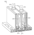
- ⁇ Example of head module structure> 4 is a perspective view (including a partial cross-sectional view) of the head module 200
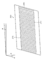
- FIG. 5 is a plan perspective view of a nozzle surface of the head module 200 shown in FIG.
- the head module 200 has an ink supply unit including an ink supply chamber 232 and an ink circulation chamber 236 on the opposite side (upper side in FIG. 4) of the ink ejection surface 277 of the nozzle plate 275. .
- the ink supply chamber 232 is connected to an ink tank (not shown) via a supply line 252, and the ink circulation chamber 236 is connected to a recovery tank (not shown) via a circulation line 256.
- a plurality of nozzle openings 280 are formed on the ink discharge surface 277 of the nozzle plate 275 of one head module 200 by a two-dimensional nozzle arrangement.
- the head module 200 has an end surface on the long side along the V direction having an inclination of angle ⁇ with respect to the X direction, and a short side of the short side along the W direction having an inclination of angle ⁇ with respect to the Y direction. It has a parallelogram planar shape having end faces, and a plurality of nozzle openings 280 are arranged in the row direction along the V direction and the column direction along the W direction.
- the arrangement of the nozzle openings 280 is not limited to the mode illustrated in FIG. 5, and a plurality of nozzle openings 280 are arranged along the row direction along the X direction and the column direction obliquely intersecting the X direction. May be.
- the “matrix arrangement” of the nozzle openings 280 means that the arrangement pitch between the nozzle openings 280 is uniform in the projected nozzle group in which all the nozzle openings 280 are projected so as to be arranged along the X direction. Means the nozzle arrangement.
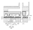
- FIG. 6 is a cross-sectional view showing the internal structure of the head module 200.
- Reference numeral 214 is an ink supply path
- 218 is a pressure chamber (liquid chamber)
- 216 is an individual supply path that connects each pressure chamber 218 and the ink supply path 214
- 220 is a nozzle communication path that connects the pressure chamber 218 to the nozzle opening 280
- 226 Is a circulation individual flow path connecting the nozzle communication path 220 and the circulation common flow path 228.
- the vibration plate 266 is provided on the flow channel structure 210 constituting these flow channel portions (214, 216, 218, 220, 226, 228).
- a piezoelectric element 230 having a laminated structure of a lower electrode (common electrode) 265, a piezoelectric layer 231, and an upper electrode (individual electrode) 264 is disposed on the vibration plate 266 via an adhesive layer 267.
- the upper electrode 264 is an individual electrode patterned according to the shape of each pressure chamber 218, and a piezoelectric element 230 is provided for each pressure chamber 218.
- the ink supply path 214 is connected to the ink supply chamber 232 described with reference to FIG. 4, and ink is supplied from the ink supply path 214 to the pressure chamber 218 via the individual supply path 216.
- a driving voltage to the upper electrode 264 of the piezoelectric element 230 provided in the corresponding pressure chamber 218 in accordance with the image signal of the image to be drawn, the piezoelectric element 230 and the diaphragm 266 are deformed and the pressure chamber.
- the volume of 218 changes, and ink is ejected from the nozzle opening 280 via the nozzle communication path 220 due to the pressure change accompanying this.
- Ink droplets can be ejected from the nozzle openings 280 by controlling the driving of the piezoelectric elements 230 corresponding to the nozzle openings 280 according to the dot arrangement data generated from the image information. While the paper P (see FIG. 3) is transported in the Y direction at a constant speed, a desired image is recorded on the paper P by controlling the ink ejection timing from each nozzle opening 280 according to the transport speed. be able to.
- the pressure chamber 218 provided corresponding to each nozzle opening 280 has a substantially square planar shape, and the outlet to the nozzle opening 280 is provided at one of the diagonal corners.
- the other side is provided with a supply ink inlet (individual supply path) 216.
- the shape of the pressure chamber is not limited to a square.
- the planar shape of the pressure chamber may have various forms such as a quadrangle (rhombus, rectangle, etc.), a pentagon, a hexagon and other polygons, a circle, and an ellipse.
- a circulation outlet (not shown) is formed in the nozzle part 281 including the nozzle opening 280 and the nozzle communication path 220, and the nozzle part 281 communicates with the circulation individual flow path 226 via the circulation outlet.
- ink that is not used for ejection is collected (circulated) to the circulation common channel 228 via the circulation individual channel 226.
- the circulation common flow path 228 is connected to the ink circulation chamber 236 described with reference to FIG. 5, and the ink is always collected to the circulation common flow path 228 through the circulation individual flow path 226, thereby non-ejection (non-drive). At this time, thickening of the ink of the nozzle portion 281 is prevented.
- the configuration of the inkjet head 56 described here is merely an example, and can be changed, added, or deleted as appropriate.
- the arrangement of the nozzle openings 280 is not limited to the matrix arrangement, and an aspect in which the nozzle openings 280 are arranged in a line along the X direction (see FIG. 5) or an aspect in which two lines are arranged in a staggered manner. It is possible to adopt.
- FIG. 7 is a schematic configuration diagram of the sheet reversing unit 22 illustrated in FIG. 7 that are the same as or similar to those in FIG. 1 are assigned the same reference numerals, and descriptions thereof are omitted.
- the pressing cylinder 71 is provided with an elastic layer 71B in a portion excluding the gripper arrangement portion 71C where the gripper (gripping means) 71A is arranged, and the elastic layer 71B constitutes the outer peripheral surface of the pressing cylinder 71. is doing.
- the pressing cylinder 71 With the elastic layer 71B of the pressing cylinder 71 in contact (pressing) with the paper P gripped by the gripper (gripping means) 72A of the reverse transfer cylinder 72, the pressing cylinder 71 rotates in the clockwise direction in FIG. The transfer drum 72 rotates counterclockwise in FIG. 7, and the paper P passes above the reverse transfer drum 72.
- the paper P follows the shape of the outer peripheral surface of the reverse transfer cylinder 72 and follows the rotation path of the reverse transfer cylinder 72. By carrying it, the paper P can be brought into close contact with the outer peripheral surface of the reverse transfer cylinder 72.
- An example of the material of the elastic layer 71B is rubber.
- the rubber hardness of the elastic layer 71B is a value (durometer hardness) measured using a type A durometer (conforming to ISO7169-1 (JIS K 6253-3)).
- the value (durometer hardness) measured using a type A durometer is a value obtained from the pushing depth of the push needle when the prescribed push needle is pushed into the test piece under the prescribed conditions.
- the specified conditions are as follows.
- the pressure plate has a hole of 18.0 ⁇ 5 mm in diameter and 3 ⁇ 1 mm in the center
- the support mechanism indicates the push-out amount of the push needle with zero hardness when the push needle protrudes 2.5 ⁇ 0.02 millimeters from the pressure plate.
- the thickness of the non-measurement object is 6.0 mm or more
- the dimension of the non-measurement surface is a size that can be measured at a position 12 mm or more apart.
- the number of measurement points is 5, and the measurement time is 3 seconds (or 15 seconds).
- the elastic layer 71B has a shape and an arrangement that covers the entire surface excluding the gripper arrangement portion 71C where the gripper (gripping means) 71A of the pressing cylinder 71 is arranged.
- the shape and arrangement of the elastic layer 71B are not limited to covering the entire surface except the gripper arrangement portion 71C where the gripper (gripping means) 71A of the pressing cylinder 71 is arranged.
- a part of the outer peripheral surface of the pressing cylinder 71 may be the elastic layer 71B.
- a paper guide 79 (medium support means) is provided below the pressing cylinder 71 (just below the conveyance path of the paper P passing through the lower side of the pressing cylinder 71).
- the paper guide 79 functions as support means for supporting the non-gripping portion of the paper P conveyed by the pressing cylinder 71 from the lower side of FIG.
- a suction hole (not shown) is provided on the surface of the paper guide 79 that supports the paper P, and a suction device 79A (suction means) is connected to the suction hole, and the paper P is sucked by the paper guide 79 to apply tension to the paper P.
- a suction device 79A suction means
- the aspect which performs is also preferable.
- This tension acts as a back tension that pulls the paper P upstream in the transport direction (the paper P is opposite to the traveling direction), so that the outer surface of the reversing transfer cylinder 72 is stretched while stretching the wrinkles and deformation of the paper P. It is possible to wind it closely.
- the non-gripping portion of the paper P gripped by the gripper (gripping means) 72A of the reversing transfer cylinder 72 is prevented from being lifted, fluttered, or wrinkled. .
- the gripping position here includes at least one of the gripping position in the X direction (see FIG. 3) and the gripping position in the Y direction.
- the gripper (grip means) 73A of the reversing cylinder 73 cannot grip the regular gripping position of the paper P
- the gripper (grip means) 78D of the chain gripper 78 of the reverse transport unit 24 also grips the regular gripping position of the paper P. I can't.
- the paper P is sent to the paper feeding unit 12 in a state where the regular gripping position is not gripped.
- the gripper (grip means) 40A of the paper feed drum 40 of the paper feed unit 12 cannot also grip the regular gripping position of the paper P, and the paper P remains misaligned or deformed. It is fixedly held on the image forming drum 52 of the image forming unit 18.
- an image is formed on the back surface (the surface opposite to the surface on which the image has been formed first) in the image forming unit 18 with the positional deviation occurring at the fixed position of the paper P or with the deformation occurring.
- a positional shift occurs between the front image and the back image, or the back image is deformed. That is, image formation on the back side (back side printing) cannot be performed with high accuracy.
- the gripper (gripping means from the convertible cylinder 73) 73A the sheet P When changing the position, the gripper (gripping means) 73A of the reversing cylinder 73 can grip the regular gripping position (both in the X direction and the Y direction) of the paper P.
- the regular gripping position of the paper P is grasped by the chain gripper 78 of the reversing conveyance unit 24. Thereafter, the paper P is sent to the image forming unit 18 in a state where the regular gripping position is gripped.
- the paper P Since the paper P is fixed at a normal position of the image forming drum 52 of the image forming unit 18, no positional deviation occurs between the front image and the back image, or the back image is deformed. Therefore, the back side image can be accurately formed.
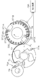
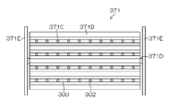
- FIG. 8 is an explanatory view of another embodiment of the pressing cylinder 71 shown in FIGS. 1 and 7, and FIG. 9 is a plan view of the pressing cylinder 371 shown in FIG. 8 and 9, the same or similar parts as those in FIGS. 1 and 7 are denoted by the same reference numerals, and the description thereof is omitted.
- the pressing cylinder 371 is provided with a blower pipe 300 (auxiliary means, air (gas) blowing means) inside.
- the blower pipe 300 is formed with a plurality of injection ports 302 and can inject air (gas) from the injection ports 302 toward the outside of the pressing drum 371.
- the air (gas) is jetted from the ejection port 302 toward the non-gripping portion of the paper P, so that the paper is applied to the outer peripheral surface of the reverse transfer cylinder 72.
- the pressing of P is assisted.
- the back tension applied to the paper P using the paper guide 79 is assisted by injecting air (gas) from the blower pipe 300 onto the paper P passing over the paper guide 79.
- the elastic layer 371 ⁇ / b> B constituting the outer peripheral surface of the pressing drum 371 has an opening 371 ⁇ / b> C corresponding to the position of the blower pipe 300.
- Air (gas) ejected from the ejection port 302 of the blower pipe 300 passes through the opening 371C and is applied to the non-gripping portion of the paper P.
- the configuration illustrated with reference numeral 371D in FIG. 9 is a rotation shaft of the pressing cylinder 371
- the configuration illustrated with reference numeral 371E in FIG. 9 is a support for supporting the rotation shaft 371D of the pressing cylinder 371. It is a member.
- the air (gas) injection from the blower pipe 300 is switched on and off in accordance with the passage timing of the paper P.
- the air (gas) injection timing (on / off) of the blower pipe 300 is controlled by an air (gas) injection control unit (not shown) based on a command signal sent from the system controller 100 of FIG.
- the amount of air (gas) injection should be relatively reduced. .
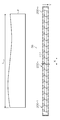
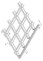
- FIG. 10 is a development view showing a structural example of the outer peripheral surface (paper support surface) of the reverse transfer cylinder 72
- FIG. 11 is an enlarged perspective view of a part of FIG.
- a concave portion 72 ⁇ / b> C having a rectangular opening shape is provided in a support region of the paper P (a region covered with the paper P when the paper P is conveyed). They are arranged at a constant arrangement pitch (arrangement interval) along the conveyance direction (Y direction) of the paper P and the width direction (X direction) of the paper P.
- a rib-like convex portion 72D is provided between the adjacent concave portions 72C.
- the outer peripheral surface of the reversing transfer cylinder 72 is formed with an uneven surface composed of the concave portion 72C and the convex portion 72D.
- the concave portion 72C having a rectangular shape (planar shape is a square shape) having the same length of the four sides and the rib-shaped convex portion 72D formed in a lattice shape are illustrated.
- the shape is not limited to the illustrated shape, and a circular shape, a polygonal shape, or the like can be appropriately employed.
- concave and convex portions formed on the outer peripheral surface of the reversing transfer cylinder 72 are not limited to the rib-like uneven shape, and a structure in which protrusions such as a hemispherical shape are formed at an arbitrary arrangement pitch may be adopted as appropriate. it can.
- the floating and wrinkling of the paper that occurs when the paper is brought into close contact with a flat surface occurs because there is no escape space for deformation (such as cockle) that occurs in the paper, and the deformation of the paper is concentrated locally.
- the paper P is three-dimensionally shaped in each concave portion 72C.
- the deformation of each direction of the paper P can be effectively absorbed.
- the direction in which the cockle is generated differs depending on the direction of the eyes of the paper P (longitudinal and horizontal eyes). In the vertical eye, the cockle tends to occur in the edge direction of the paper P. Prone to occur. Therefore, by deforming the paper P into a three-dimensional mountain shape, it is possible to efficiently absorb the deformation in any direction.
- the paper P can be placed on the outer peripheral surface of the reversal transfer cylinder 72 without causing floating or wrinkles over the entire surface of the paper P. It can be adhered.
- the height of the convex portion 72D is excessively increased, the amount of deflection of the paper P absorbed by the concave portion 72C increases, and the paper P is likely to be pressed.
- the height of the convex portion 72D (the depth of the concave portion 72C) h may be determined.
- the height of the convex portion 72D (depth of the concave portion 72C) h applied in this example is preferably more than 0.01 millimeters and not more than 3 millimeters, more preferably more than 0.3 millimeters and less than 2 millimeters.
- the paper reversing unit for reversing the front and back of the paper P is provided, and the elastic layer 71B of the pressing cylinder 71 is disposed when the paper P is replaced in the front / back reversal of the paper P.
- the paper P is prevented from being damaged when the paper P is pressed against the outer peripheral surface of the reversing transfer cylinder 72.
- the adhesion between the paper P and the outer peripheral surface of the reversing transfer cylinder 72 can be further increased.
- the reversing cylinder 73 prevents the displacement of the gripping position when the sheet P is replaced, and after the sheet P is replaced
- the gripping position By setting the gripping position to the regular gripping position, it is possible to prevent the shift of the fixing position of the paper P when forming an image on the back surface, and to perform image formation on the back surface with high accuracy.
- FIG. 12 is an overall configuration diagram of an ink jet recording apparatus 500 according to the second embodiment. 12, parts that are the same as or similar to those in FIG. 1 are given the same reference numerals, and descriptions thereof are omitted.
- the transfer cylinder 70 of the ink jet recording apparatus 10 shown in FIG. 1 is omitted, the configuration of the paper reversing unit 22 is changed, and the transfer cylinder 74 from which the paper P is transferred from the paper reversing unit 22. The position of has been changed. Except for these, the same configuration as that of the ink jet recording apparatus 10 shown in FIG. 1 can be applied.
- An ink jet recording apparatus 500 shown in FIG. 12 includes a sheet reversing unit 522 that includes a pressing cylinder 571, a reversing transfer cylinder 572, and a reversing cylinder 573, and includes a reversing cylinder 573 and a reversing conveyance unit 24 (second medium conveying unit).
- a transfer drum 574 (a component of the second medium transport unit) is provided between the component and the transfer drum.
- the paper P (not shown) is transferred from the chain gripper 64 of the drying fixing unit 20 to the pressing cylinder 571, and the paper P transferred to the pressing cylinder 571 is gripped by the gripper (gripping means) 571A of the pressing cylinder 571. .
- the pressing cylinder 571 shown in FIG. 12 rotates counterclockwise in FIG. 12, and rotates in the opposite direction to the pressing cylinder 71 shown in FIG. That is, the paper P passes above the pressing cylinder 571.
- the paper P (not shown) transferred to the pressing cylinder 571 is conveyed along the rotation path of the pressing cylinder 571 and is transferred to the reverse transfer cylinder 572.
- the paper P (not shown) delivered to the reverse transfer cylinder 572 is gripped by a gripper (gripping means) 571A of the reverse transfer cylinder 572, and the elastic layer of the pressing cylinder 571 is brought into contact with the outer peripheral surface of the reverse transfer cylinder 572. It is pressed and comes into close contact with the outer peripheral surface of the reverse transfer cylinder 572.
- a reverse transfer cylinder 572 shown in FIG. 12 is a so-called suction cylinder, and a plurality of suction holes (not shown) are arranged on a surface on which the paper P is fixedly supported according to a predetermined arrangement pattern. Is generated and the sheet P is fixedly held.
- the paper P delivered to the reverse transfer cylinder 572 is conveyed along the rotation path of the reverse transfer cylinder 572, passes below the reverse transfer cylinder 572, and is transferred to the reverse cylinder 573.
- the rotation direction of the reverse transfer cylinder 572 shown in FIG. 12 is opposite to the rotation direction of the reverse transfer cylinder 72 of FIG.
- the reversing cylinder 573 shown in FIG. 12 has a rotation direction opposite to that of the reversing cylinder 73 shown in FIG. 1 and the paper P passes through the upper side, but the structure of the reversing cylinder 73 shown in FIG. Since a series of operations can be applied, description thereof is omitted here.
- the reversing cylinder 573 replaces one end P 1 (see FIG. 7) and the other end P 2 so that the front and back surfaces of the sheet P are reversed. It is delivered to the 24 chain grippers 78 and sent to the paper feed unit 12.
- the third transfer cylinder 574 shown in FIG. 12 rotates in the opposite direction to the transfer cylinder 74 shown in FIG. 1, but the same structure as the transfer cylinder 74 shown in FIG. 1 can be applied. Description of is omitted.
- the paper P whose front and back are not reversed by the reversing cylinder 573 is transferred from the reversing cylinder 573 to the chain gripper 77 of the stacking unit 26 and sent to the paper discharge tray 76 (see FIG. 1).
- the same operational effects as those of the ink jet recording apparatus 10 according to the first embodiment can be obtained, and the transfer cylinder 70 of the aspect illustrated in FIG. 1 can be reduced.
- space saving of the apparatus can be achieved.
- images are formed on both sides of the paper P using one (common) image forming unit 18 in the inkjet recording apparatus that forms images on both sides of the paper P.
- one (common) image forming unit 18 in the inkjet recording apparatus that forms images on both sides of the paper P.
- the second image forming unit may be provided in the subsequent stage of the sheet reversing unit 22 (522), and the image may be formed in the second image forming unit after the front and back of the sheet P are reversed.
- a processing unit that performs processing (for example, coating processing) while holding the paper P smoothly is provided, and after forming an image on the surface of the paper P, the front and back of the paper P are reversed. A configuration in which processing is performed on the back surface of the paper P may be applied.
- the reverse conveyance unit 24 is configured to convey the paper P with the front and back reversed to the second image forming unit or the processing unit.
- the inkjet recording apparatus 10 (500) described above discharges ink (aqueous ink) of each color from the inkjet heads 56C, 56M, 56Y, and 56K onto the conveyed medium P and the first medium conveyance process for conveying the sheet P.
- An image forming process, a medium reversing process for reversing the first side and the second side of the paper P on which the image is formed, and a paper P having the first side and the second side reversed are conveyed to the paper feeding unit 12.
- a second medium transporting step that functions as an apparatus that realizes a medium transporting method.
- a pressing cylinder 71 (571) including a gripper (gripping means) 71A (571A) that grips one end P1 of the sheet P on which an image is formed, and a delivery from the pressing cylinder 71 gripper for gripping one end P 1 of the sheet P (the gripping means) 72A (572A) inverted transfer cylinder 72 (572) equipped with a, and one end P of the delivered paper P from the reversing transfer cylinder 72 comprising one or one end P 1 and the opposite side of the gripper for gripping the other end P 2 (grip means) 73A (573A), a first surface and a second surface of the paper P holding the other end P 2
- the pressing cylinder 71 has an outer peripheral surface on which an elastic layer 71B (371B) is formed.
- the elastic layer 71B is brought into contact with the paper P gripped by the gripper (gripping means) 72A of the reverse transfer cylinder 72 when the paper P is delivered to the reverse transfer cylinder 72, so that the gripper of the reverse transfer cylinder 72 is brought into contact.
- (Gripping means) A pressing force applying step of pressing the paper P gripped by 72A against the outer peripheral surface of the reversing transfer cylinder 72 and applying a pressing force to the paper P gripped by the gripper (gripping means) 72A of the reversing transfer cylinder 72. included.
- the functions realized by the respective units of the above-described inkjet recording apparatus 10 (500) can be configured as steps included in the above-described medium conveyance method (image forming method).
- the water-based ink applied to the ink jet recording apparatus shown in this example includes a color material (pigment), a dispersant, a surfactant, thermoplastic resin particles (polymer particles), a water-soluble organic solvent (wetting agent, penetrant), water , And other additives.
- the material, physical properties, and composition ratio of each component are appropriately determined in consideration of ejection stability by the ink jet method, various conditions in image formation, processing conditions before and after image formation, handling during paper conveyance, safety, and the like.
- ink jet recording apparatus and the medium transport method described above can be changed, added, and deleted as appropriate without departing from the spirit of the present invention. Moreover, it is also possible to combine each structural example mentioned above suitably.
- the drying fixing unit 20 may be configured as a drying processing unit that performs a drying process on the paper P.
- a second medium transporting means for gripping and transporting the medium by the gripping means, and the medium reversing means includes a pressing cylinder having a gripping means for gripping the medium delivered from the first medium transporting means, and a pressing cylinder.
- the first surface and the second surface of the medium are reversed by gripping the end opposite to the end gripped by the reversing transfer cylinder of the medium,
- the medium reversed with respect to the second surface is transferred to the second medium transport means, and the pressing cylinder has an outer peripheral surface on which an elastic layer is formed, and when the medium is transferred to the reverse transfer cylinder, the holding means for the reverse transfer cylinder
- the elastic layer formed on the outer peripheral surface of the pressing cylinder is brought into contact with the medium gripped by the gripping means of the reverse transfer cylinder, and the medium is pressed against the outer peripheral surface of the reverse transfer cylinder to Since the medium is brought into close contact with the surface, when the gripping means of the reversing cylinder grips the end opposite to the end gripped by the gripping means of the reversing transfer cylinder, the other end of the medium is prevented from floating or wrinkling. Is done. Accordingly, the grip position shift when the medium is replaced is prevented, and the occurrence of wrinkles or the like of the medium gripped and transported by the gripping means is prevented.
- the medium is prevented from being damaged when the medium is brought into close contact with the reversing transfer cylinder.
- the elastic layer has a rubber hardness measured using a type A durometer of 30 degrees or more and 80 degrees or less.
- the rubber hardness measured using the type A durometer of the elastic layer is set to 30 degrees or more and 80 degrees or less, an appropriate elastic force is applied when the medium is pressed.
- the medium can be reliably pressed against the outer peripheral surface of the reversing transfer cylinder without being damaged and without causing a positional shift of the medium.
- auxiliary means for assisting the pressing of the medium against the reverse transfer cylinder is provided.
- the medium can be brought into close contact with the reversing transfer cylinder more reliably.
- the auxiliary means includes gas blowing means for blowing gas from the inside of the pressing cylinder to the medium held by the holding means of the reverse transfer cylinder, and the pressing cylinder An opening is formed in the outer peripheral surface of the gas spraying position of the gas spraying means.
- the gas can be blown onto the medium gripped by the gripping means of the reversing transfer cylinder, so that the medium can be more closely attached to the reversing transfer cylinder.
- the auxiliary means is a medium support that is provided below the pressing cylinder and supports the first surface or the second surface of the medium.
- suction means for generating a suction pressure in a suction hole provided in a support surface for supporting the medium of the medium support means.
- the sheet can be brought into close contact with the reverse transfer cylinder by sucking the first surface or the second surface of the medium and applying a suction pressure opposite to the transport direction to the medium.
- the reverse transfer cylinder has an outer peripheral surface on which irregularities are formed.
- the sixth aspect by forming irregularities on the outer peripheral surface of the reversing transfer cylinder to which the medium is brought into close contact, the deformation generated in the medium is corrected, and the medium can be more firmly brought into close contact with the outer peripheral surface of the reversing transfer cylinder. it can.
- the unevenness formed on the reverse transfer cylinder has a thickness of more than 0.3 millimeters and less than 2 millimeters.
- the unevenness formed on the outer peripheral surface of the reversing transfer cylinder is set to a thickness of more than 0.3 millimeters and less than 2 millimeters, thereby obtaining a deflection amount that effectively corrects the deformation of the medium. And it is possible to prevent pressing marks on the medium.
- the second medium conveying unit conveys the medium delivered from the medium reversing unit to the medium supplying unit.
- the displacement of the grip position of the medium after the medium is changed is shifted. This prevents the positional deviation between the image on the first surface and the image on the second surface.
- the medium subjected to the drying process after the image formation is likely to be deformed
- the medium is brought into close contact with the reverse transfer cylinder by applying the pressing force to the medium that has been deformed by the drying process. be able to.
- the ink jet head ejects water-based ink.
- the drying process is performed after the image formation on the first side and the medium is likely to be deformed, a pressing force is applied to the medium in which the deformation due to the drying process has occurred.
- the said medium can be stuck to an inversion transfer cylinder.
- the first medium conveying means includes an image forming and conveying means for conveying the medium in an area where the image of the image forming means is formed; And a post-processing transport unit that transports a medium on which an image is formed in a processing area of the post-processing unit in which post-processing after image formation by the forming unit is performed.
- chain conveying means (chain gripper) having a form in which a gripping means for gripping a medium is attached to an endless chain.
- pre-processing means for pre-processing the medium before image formation by the image forming means
- pre-processing transport means for transporting the medium in the pre-processing area of the pre-processing means
- Examples of the pretreatment include a treatment liquid applying unit that applies a treatment to agglomerate or insolubilize the ink to the medium, and a treatment liquid drying unit that dries the treatment liquid applied to the medium.
- the ink jet recording apparatus according to any one of the first to eleventh aspects, further comprising: an accumulation unit that accumulates the medium on which the image is formed; When the first surface and the second surface are not reversed, there is provided switching means for switching the transport destination of the medium on which the image is formed from the second medium transport means to the stacking means.
- the stacking unit in the twelfth mode there is a mode including a stacking and transporting unit that transports the medium delivered from the medium reversing unit, and a stocker that stacks the medium transported by the stacking and transporting unit.
- chain conveying means (chain gripper) having a form in which a gripping means for gripping a medium is attached to an endless chain.
- Medium reversing means comprising a reversing cylinder for reversing the first surface and the second surface of the medium by gripping the end opposite to the end gripped by the medium reversing transfer cylinder when forming an image on two surfaces
- the elastic layer formed on the outer peripheral surface of the pressing cylinder is brought into contact with the medium gripped by the reversing transfer cylinder gripping means, and is gripped by the reversing transfer cylinder gripping means.
- a medium conveying method including a pressing force applying step of applying a pressing force to a medium to be performed.
- the elastic layer has a rubber hardness measured using a type A durometer of 30 degrees or more and 80 degrees or less.
- assistant process which assists pressing of the medium to an inversion transfer cylinder is preferable.
- the correction step includes a gas blowing step of blowing gas from the inside of the pressing cylinder to the medium held by the holding means of the reverse transfer cylinder through the opening on the outer peripheral surface.
- the auxiliary process includes a suction process in which a suction pressure is applied to the first surface or the second surface of the medium.
- the second medium transport step transports the medium to the medium supply unit.
- Including a drying step of performing a drying process on a medium on which an image is formed by the image forming process, and the medium reversal step is a medium on which the drying process has been delivered, and a medium on which the delivered drying process has been performed
- a mode in which the first surface and the second surface are reversed and sent to the second medium conveying step is preferable.
- the image forming step is preferably an aspect in which an image is formed on the first surface or the second surface of the medium using water-based ink.
Landscapes
- Engineering & Computer Science (AREA)
- Mechanical Engineering (AREA)
- Ink Jet (AREA)
- Feeding Of Articles By Means Other Than Belts Or Rollers (AREA)
Abstract
媒体の変形に起因する媒体を咥え替える際の把持位置の位置ずれ、しわ等の発生が防止され、高精度に媒体の搬送を行うことを可能とするインクジェット記録装置及び媒体搬送方法を提供する。媒体に画像を形成するインクジェット記録装置において、媒体(P)の第1面と第2面とを反転させる媒体反転手段(22)は、グリッパ(71A)を備えた押付胴71、グリッパ(72A)を備えた反転渡し胴(72)、及びグリッパ(73)を備え、反転渡し胴によって把持される端(P1)と反対側の端(P2)を把持して第1面と第2面とを反転させる反転胴(73)を具備し、押付胴の弾性層を反転渡し胴のグリッパによって把持される媒体に接触させて媒体に押し付け力を付与して、媒体を反転渡し胴に密着させる。
Description
本発明はインクジェット記録装置及び媒体搬送方法に係り、特にインクジェット記録装置における媒体反転技術及び媒体搬送技術に関する。
汎用の画像形成装置として、インクジェット記録装置が知られている。インクジェット記録装置は、汎用の印刷用紙(塗工紙など、セルロースを主体とした用紙)に水性インク(水及び水に可溶な溶媒に染料、顔料などの色材を溶解又は分散させたインク)を用いて印刷すると、印刷後の用紙にカール、カックル(波打ち)等の変形が生じるという問題がある。
特許文献1は、用紙を吸着保持する吸着保持面に所定パターンの凹凸が形成され、凹部内に吸引穴が形成された搬送手段を具備するインクジェット記録装置が記載されている。特許文献1に記載のインクジェット記録装置は、用紙に生じたカックルが凹部に吸収され、用紙を吸着保持面に密着させている。
特許文献2は、用紙の支持面に複数のリブが配置された搬送手段を具備するインクジェット記録装置が記載されている。特許文献2に記載のインクジェット記録装置は、リブの間隔または高さ、もしくはその両方を最適化することで、用紙搬送における用紙の浮きを防止している。
グリッパを具備する胴を備え、グリッパを用いて用紙を把持して搬送する印刷装置において、胴に対して用紙が浮き上がった状態で巻き付けられると、用紙を咥え替える際に用紙の把持位置がずれてしまうという問題がある。
特許文献3は、反転胴の用紙搬送方向上流側の渡し胴によって搬送される用紙の紙尻を反転胴のグリッパで咥え替えて用紙の表裏を反転させる用紙の反転機構を備えた両面印刷機が記載されている。特許文献3に記載の印刷機は、第2渡し胴に用紙を密着させて巻き付けるために用紙の受け渡し部分に向けてエアを吹き付けるエア供給手段を備えている。
しかしながら、特許文献1および2に記載のインクジェット記録装置は、用紙が吸着保持される形態において用紙の浮き等を防止するものとして有効であるものの、用紙の一部を把持して搬送する形態では、用紙の把持されていない部分の浮き等を防止することは困難である。
また、インクジェット方式を用いて用紙の両面に画像を形成すると、オフセット方式などの他の方式の画像形成装置と比較して、用紙に付着させる水の量が多いために、画像形成後の用紙の変形が大きくなってしまう。
特許文献3に記載の第1渡し胴から第2渡し胴への用紙の受け渡し部分に向けてエアを吹き付ける構成、ペーパーガイドを用いて用紙を搬送方向と反対向きに引っ張る構成をインクジェット方式の画像形成に適用したとしても、オフセット印刷機等に比べてインクジェット方式では表面の画像形成後の用紙の変形が大きいことを考慮すると、第2渡し胴へ用紙をきっちりと密着させることは困難である。
第2渡し胴に用紙を密着させることができないと、用紙の把持されていない後端の浮き、幅方向のたるみなどが生じてしまい、反転胴によって用紙を咥え替える際に把持位置の位置ずれ、把持位置のしわ(たるみ)などが発生してしまう。
また、インクジェット方式の画像形成では、画像形成の際に用紙を平滑に保持する必要があるにもかかわらず、用紙の把持がたるんでしまうと用紙を平滑に保持することができなくなってしまう。これらの課題は、インクジェット方式の両面画像形成に限定されるものではなく、用紙の変形が生じる枚葉の媒体に対して液体を用いた処理を行う場合にも同様の課題が存在する。
本発明はこのような事情に鑑みてなされたもので、媒体の変形に起因する媒体を咥え替える際の把持位置の位置ずれ、しわ等の発生が防止され、高精度に媒体の搬送を行うことを可能とするインクジェット記録装置及び媒体搬送方法を提供することを目的とする。
上記目的を達成するためのインクジェット記録装置は、媒体を供給する媒体供給手段と、媒体供給手段から供給された媒体を把持する把持手段を具備し、把持手段によって媒体を把持して搬送する第1媒体搬送手段と、把持手段によって把持され第1媒体搬送手段によって搬送される媒体にインクを吐出させるインクジェットヘッドを具備する画像形成手段と、第1媒体搬送手段から受け渡された媒体の第1面と第1面の裏面の第2面とを反転させる媒体反転手段と、媒体反転手段によって第1面と第2面とを反転させた媒体を把持する把持手段を備え、第1面と第2面とを反転させた媒体を把持手段によって把持して搬送する第2媒体搬送手段と、を備え、媒体反転手段は、第1媒体搬送手段から受け渡された媒体を把持する把持手段を備えた押付胴、押付胴から受け渡された媒体を把持する把持手段を備えた反転渡し胴、及び反転渡し胴から受け渡された媒体を把持する把持手段を備えた反転胴を具備し、反転胴は、第1面に画像が形成された媒体の第2面に画像を形成する際に、媒体の反転渡し胴によって把持される端と反対側の端を把持して媒体の第1面と第2面とを反転させ、第1面と第2面とを反転させた媒体を第2媒体搬送手段へ受け渡し、押付胴は、弾性層が形成された外周面を有し、反転渡し胴に媒体を受け渡す際に反転渡し胴の把持手段によって把持される媒体に弾性層を接触させて、反転渡し胴の把持手段によって把持される媒体に押付力を付与する。
反転渡し胴の把持手段に把持された媒体に押付胴の外周面に形成された弾性層を接触させて反転渡し胴の外周面に媒体を押し付けて反転渡し胴の外周面に媒体を密着させるので、反転胴の把持手段によって反転渡し胴の把持される端と反対側の端を把持する際に、媒体の他方の端の浮き、しわ等の発生が防止される。したがって、媒体が咥え替えられる際の把持位置ずれが防止され、把持手段によって把持されて搬送される媒体のしわ等の発生が防止される。また、媒体に弾性層を接触させることで、反転渡し胴に媒体を密着させる際の媒体の破損が防止される。
以下、添付図面に従って本発明の好ましい実施の形態について詳説する。
〔第1実施形態:インクジェット記録装置の全体構成〕
図1は、本発明の第1実施形態に係るインクジェット記録装置の全体構成図である。
図1は、本発明の第1実施形態に係るインクジェット記録装置の全体構成図である。
図1に示すインクジェット記録装置10は、枚葉の用紙P(媒体)に水性インク(水及び水に可溶な溶媒に染料、顔料などの色材を溶解又は分解させたインク)を用いてインクジェット方式で画像を記録するインクジェット記録装置である。
インクジェット記録装置10は、主として、用紙Pを給紙する給紙部12(媒体供給手段)と、給紙部12から給紙された用紙Pの表面(又は裏面)に処理液を付与するプレコート部14と、プレコート部14で処理液が付与された用紙Pの乾燥処理を行う処理液乾燥処理部16と、処理液乾燥処理部16で乾燥処理が施された用紙Pの表面(又は裏面)に水性インクを用いてインクジェット方式で画像を記録する画像形成部18(画像形成手段)と、画像形成部18で画像が記録された用紙Pの乾燥処理を行う乾燥定着部20(乾燥手段)と、両面印刷の際に用紙Pの表面と裏面とを反転させる用紙反転部22(用紙反転手段)と、用紙反転部22によって表面と裏面とを反転させた用紙Pを給紙部12へ搬送する反転搬送部24(第2媒体搬送手段)と、画像形成が完了し、乾燥定着処理が施された用紙Pが集積される集積部26(集積手段)と、を含んで構成される。
〈給紙部〉
給紙部12は、主として、給紙台30と、サッカー装置32と、給紙ローラ対34と、フィーダボード36と、給紙ドラム40を含んで構成され、給紙台30に積載された用紙Pを1枚ずつプレコート部14へ給紙する。
給紙部12は、主として、給紙台30と、サッカー装置32と、給紙ローラ対34と、フィーダボード36と、給紙ドラム40を含んで構成され、給紙台30に積載された用紙Pを1枚ずつプレコート部14へ給紙する。
給紙台30の上に積載された用紙Pは、サッカー装置32によって上から順に1枚ずつ引き上げられて、給紙ローラ対34(上下一対のローラ34A,34Bの間)に給紙される。
給紙ローラ対34に給紙された用紙Pは、上下一対のローラ34A,34Bによって前方に送り出され、フィーダボード36の上に載置される。フィーダボード36の上に載置された用紙Pは、給紙ドラム40に受け渡される。そして、給紙ドラム40のグリッパ(把持手段)40Aにより先端部を把持されて(咥えられて)プレコート部14へと搬送される。
〈プレコート部〉
プレコート部14は、主として、用紙Pを搬送する処理液付与ドラム42(第1媒体搬送手段の一例)と、処理液付与ドラム42によって搬送される用紙Pの表面に所定の処理液を付与する処理液付与ユニット44と、を含んで構成され、用紙Pの表面に処理液を付与(塗布)する。
プレコート部14は、主として、用紙Pを搬送する処理液付与ドラム42(第1媒体搬送手段の一例)と、処理液付与ドラム42によって搬送される用紙Pの表面に所定の処理液を付与する処理液付与ユニット44と、を含んで構成され、用紙Pの表面に処理液を付与(塗布)する。
用紙Pの表面に塗布される処理液は、後段の画像形成部18で用紙Pに打滴される水性インク中の色材を凝集させる機能を有する処理液が塗布される。用紙Pの表面に処理液を塗布して水性インクを打滴することにより、汎用の印刷用紙を用いても着弾干渉等を起こすことなく、高品位な印刷を行うことができる。
給紙部12の給紙ドラム40から受け渡された用紙Pは、処理液付与ドラム42に受け渡される。処理液付与ドラム42は、用紙Pの先端をグリッパ(把持手段)42Aで把持して回転することにより、用紙Pを外周面に巻き掛けて搬送する。
この搬送過程で、処理液皿44Bから計量ローラ44Cにより一定量に計量された処理液が付与された塗布ローラ44Aを用紙Pの表面に押圧当接させることで、用紙Pの表面に処理液が塗布される。なお、処理液を塗布する形態はローラ塗布に限定されず、インクジェット方式、ブレードによる塗布など、他の形態を適用することも可能である。
〈処理液乾燥処理部〉
処理液乾燥処理部16は、主として、用紙Pを搬送する処理液乾燥処理ドラム46(第1媒体搬送手段の構成要素)と、用紙Pの裏面を支持(ガイド)する用紙搬送ガイド48と、処理液乾燥処理ドラム46によって搬送される用紙Pの表面に熱風を吹き当てて乾燥させる処理液乾燥処理ユニット50と、を含んで構成され、表面に処理液が付与された用紙Pに対して乾燥処理を施す。
処理液乾燥処理部16は、主として、用紙Pを搬送する処理液乾燥処理ドラム46(第1媒体搬送手段の構成要素)と、用紙Pの裏面を支持(ガイド)する用紙搬送ガイド48と、処理液乾燥処理ドラム46によって搬送される用紙Pの表面に熱風を吹き当てて乾燥させる処理液乾燥処理ユニット50と、を含んで構成され、表面に処理液が付与された用紙Pに対して乾燥処理を施す。
プレコート部14の処理液付与ドラム42から処理液乾燥処理ドラム46へ受け渡された用紙Pは、処理液乾燥処理ドラム46に具備されるグリッパ(把持手段)46Aによって先端を把持される。
また、用紙Pは、表面(処理液が塗布された面)を内側に向けた状態で裏面を用紙搬送ガイド48によって支持される。この状態で処理液乾燥処理ドラム46を回転させることにより用紙Pを搬送させる。
処理液乾燥処理ドラム46によって用紙Pが搬送される過程で、処理液乾燥処理ドラム46の内側に設置された処理液乾燥処理ユニット50から用紙Pの表面へ熱風が吹き当てられて、用紙Pに乾燥処理が施され、処理液中の溶媒成分が除去されて、用紙Pの表面にインク凝集層が形成される。
〈画像形成部〉
画像形成部18は、主として、用紙Pを搬送する画像形成ドラム52(第1媒体搬送手段の一例、画像形成搬送手段)と、用紙PにC(シアン),M(マゼンダ),Y(イエロー),K(ブラック)の各色のインク液滴を吐出するインクジェットヘッド56C,56M,56Y,および56Kと、用紙Pに記録された画像を読み取るインラインセンサ58と、を含んで構成される。
画像形成部18は、主として、用紙Pを搬送する画像形成ドラム52(第1媒体搬送手段の一例、画像形成搬送手段)と、用紙PにC(シアン),M(マゼンダ),Y(イエロー),K(ブラック)の各色のインク液滴を吐出するインクジェットヘッド56C,56M,56Y,および56Kと、用紙Pに記録された画像を読み取るインラインセンサ58と、を含んで構成される。
用紙Pの受け渡し位置とインクジェットヘッド56Cとの間に、画像形成ドラム52によって搬送される用紙Pを押圧して、用紙Pを画像形成ドラム52の外周面に密着させる用紙押さえローラを備えてもよい。
処理液層が形成された用紙Pの表面にC,M,Y,Kの各色のインクの液滴を打滴して、用紙Pの表面にカラー画像を描画する。インクミストを捕捉するミストフィルタ、及び画像形成ドラム52を冷却するドラム冷却ユニットを備える態様も好ましい。
本例に適用されるインクジェットヘッドには、圧電素子のたわみ変形を利用してインクを吐出させる圧電方式(図6参照)、インクを加熱して膜沸騰現象を発生させてインクを吐出させるサーマル方式(不図示)、帯電させたインクを静電気力によって記録媒体へ着弾させる静電方式(不図示)など、様々な吐出方式を適用することができる。
また、本例に適用されるインクジェットヘッドは、用紙Pの全幅(用紙Pの相対移動方向と直交する主走査方向の全長)に対応する長さにわたってノズルが形成されるライン型ヘッドが適用される(図3参照)。もちろん、シリアル方式の画像形成を適用することも可能である。
「シリアル方式の画像形成」とは、用紙Pの搬送方向に沿ってノズル列が配置されたインクジェットヘッドを備え、用紙Pの幅方向(用紙Pの搬送方向と直交する方向)におけるインクジェットヘッドの走査と、用紙Pの搬送を間欠的に繰り返すことで記録を行う方式である。
ここで、本明細書における「直交」とは、90°をなして交差する態様だけでなく、90°未満又は90°を超えて交差する態様のうち、90°をなして交差する態様と同様の作用効果を奏する「実質的な直交」が含まれることとする。
処理液乾燥処理部16の処理液乾燥処理ドラム46から画像形成ドラム52へ受け渡された用紙Pは、画像形成ドラム52に具備されるグリッパ(把持手段)52Aによって先端を把持される。用紙押さえローラを備える態様では、用紙Pを用紙押さえローラの下を通過させることで、用紙Pは画像形成ドラム52の外周面に密着させることができる。
画像形成ドラム52の外周面に密着させた用紙Pは、画像形成ドラム52の外周面に形成された吸引穴(不図示)に発生させた吸引圧力によって吸引されて、画像形成ドラム52の外周面に吸引保持される。
画像形成ドラム52の外周面に吸引保持され搬送される用紙Pは、各インクジェットヘッド56C,56M,56Y,および56Kの直下のインク打滴領域を通過する際に、各インクジェットヘッド56C,56M,56Y,および56KからC,M,Y,およびKの各色のインクの液滴が打滴されカラー画像が描画される。
用紙Pに打滴されたインクは、用紙Pに形成された処理液層(インク凝集層)と反応し、フェザリングやブリーディング等を起こすことなく用紙Pの表面に定着し、用紙Pには高品位な画像が形成される。
インクジェットヘッド56C,56M,56Y,および56Kによって画像が形成された用紙Pがインラインセンサ58の読取領域を通過する際に、用紙Pに形成された画像が読み取られる。
インラインセンサ58による画像の読み取りは必要に応じて行われ、画像の読取データから吐出不良(吐出異常)、濃度むら等の画像欠陥(画像異常)の検査が行われる。インラインセンサ58の読取領域を通過した用紙Pは、吸引が解除された後、乾燥定着部20(画像形成後の後処理手段)へと受け渡される。
〈乾燥定着部〉
乾燥定着部20は、チェーングリッパ64(第1媒体搬送手段の構成要素、後処理搬送手段)によって搬送される用紙Pに対して乾燥処理、及び定着処理を施す乾燥定着ユニット68を含んで構成され、画像形成後の用紙Pに対して乾燥処理及び定着処理を施し、用紙Pの表面に残存する液体成分を除去し、用紙Pに画像を定着させる。
乾燥定着部20は、チェーングリッパ64(第1媒体搬送手段の構成要素、後処理搬送手段)によって搬送される用紙Pに対して乾燥処理、及び定着処理を施す乾燥定着ユニット68を含んで構成され、画像形成後の用紙Pに対して乾燥処理及び定着処理を施し、用紙Pの表面に残存する液体成分を除去し、用紙Pに画像を定着させる。
乾燥定着ユニット68の構成例として、ハロゲンヒータ、赤外線(IR)ヒータ等の熱源と、熱源によって熱せられた空気(気体、流体)を用紙Pへ吹き付けるファンと、を具備する態様が挙げられる。乾燥処理、定着処理後の用紙Pを冷却するための冷却装置を備えてもよい。
紫外線などの活性光線の照射により硬化するインク(紫外線(活性光線)硬化型インク)が用いられる場合には、乾燥定着ユニット68に紫外線光源が具備され、定着処理として紫外線(活性光線)の照射がされる。
画像形成部18の画像形成ドラム52からチェーングリッパ64へ受け渡された用紙Pは、チェーングリッパ64に具備されるグリッパ(把持手段)64Dによって先端を把持される。
チェーングリッパ64は、第1スプロケット64A及び第2スプロケット64Bに一対の無端状のチェーン64Cが巻き掛けられた構造を有している。
チェーングリッパ64は、複数のグリッパ(把持手段)64Dが用紙Pの幅方向に沿って配置されており、用紙Pの幅方向に沿って並べられたグリッパ(把持手段)64Dの一群が、用紙Pの搬送方向(チェーン64Cの移動方向)に沿って配置されている。グリッパ(把持手段)64Dは、爪と爪台(ともに不図示)の間に用紙Pの先端をはさみ込んで、用紙Pを把持する。
グリッパ(把持手段)64D以外の他のグリッパ(把持手段)も、爪と爪台の間に用紙Pの端をはさみ込んで用紙Pを把持する同様の構造を有している。
チェーングリッパ64によって搬送される用紙Pの後端(画像が形成されていない用紙Pの裏面)は、チェーングリッパ64との間の一定の距離を離して配置されたガイドプレート(不図示)の用紙保持面に吸引保持される。
乾燥定着部20は、乾燥処理及び定着処理が施された用紙Pを次段の用紙反転部22へ受け渡す渡し胴70を備えている。渡し胴70は、用紙Pを把持するグリッパ(把持手段)70Aを備え、チェーングリッパ64によって搬送された用紙Pを把持し、図1における反時計回りに回転して用紙Pを回転軌道に沿って搬送する。
乾燥定着部20の渡し胴70は、回転角度が180°ずらされた2か所の位置にグリッパ(把持手段)70Aが配置される構造を有している。
本例では、乾燥定着部20において用紙Pを搬送する手段としてチェーングリッパ64を例示したが、乾燥定着部20において用紙Pを搬送する手段はチェーングリッパ64に限定されない。
例えば、乾燥定着部20において用紙Pを搬送する手段として、グリッパ(把持手段)を備えた圧胴、渡し胴を備える態様(複数の圧胴と複数の渡し胴とを用紙Pの搬送方向に沿って配置する態様)も可能である。また、グリッパ(把持手段)を備えた搬送ベルトなどの搬送形態を適用することも可能である。さらに、画像形成部18との用紙Pの受け渡し位置、用紙反転部22との用紙Pの受け渡し位置に渡し胴などの用紙Pの搬送経路を調整する部材が適宜具備される。
〈用紙反転部〉
用紙反転部22は、押付胴71、反転渡し胴72、及び反転胴73(切換手段の構成要素)を含んで構成され、用紙Pの搬送方向上流側から下流側へ上記の順序でこれらが配置されている。
用紙反転部22は、押付胴71、反転渡し胴72、及び反転胴73(切換手段の構成要素)を含んで構成され、用紙Pの搬送方向上流側から下流側へ上記の順序でこれらが配置されている。
用紙反転部22は、用紙Pの表面と裏面とを反転させる手段として機能し、かつ、用紙Pを集積部26へ送るか、反転搬送部24へ送るかを切り換える用紙Pの搬送経路を切り換える手段として機能する。
なお、本明細書では、用紙Pの片面のみに画像が形成される場合の画像が形成される面、両面に画像が形成される場合の先に画像が形成される面を便宜的に「表面(第1面)」とし、両面に画像が形成される場合の後に画像が形成される面を便宜的に「裏面(第2面)」とする。
チェーングリッパ64、渡し胴70によって搬送された用紙Pは、用紙反転部22の押付胴71に受け渡される。押付胴71に受け渡された用紙Pは、反転渡し胴72を経由して反転胴73へ送られる。
押付胴71によって搬送される用紙Pは、押付胴71のグリッパ(把持手段)71Aによって把持され、反転渡し胴72によって搬送される用紙Pは、反転渡し胴72のグリッパ(把持手段)72Aによって把持される。
押付胴71は、用紙Pを反転渡し胴72へ受け渡す際に、用紙Pを反転渡し胴72の外周面に押し付ける押付力を付与する手段として機能する。用紙Pを反転渡し胴72へ受け渡す際に、用紙Pを反転渡し胴72の外周面に押し付けて、用紙Pを反転渡し胴72の外周面に密着させることで、反転渡し胴72のグリッパ(把持手段)72Aに把持されていない用紙Pの他方の端(図1中不図示、図7に符号P2を付して図示)を反転胴73が把持して用紙Pを咥え替える際の把持位置の位置ずれが防止される。
押付胴71の外周面は、弾性層(図1中不図示、図7に符号71Bを付して図示)によって形成されており、弾性層を用紙Pに接触させて用紙Pの裏面(弾性層との接触面と反対側の面)を反転渡し胴72の外周面に密着させる(詳細後述)。
図1における詳細な図示は省略するが、反転渡し胴72は、用紙Pの搬送方向における長さに対応して、用紙Pの裏面を支持する部分の用紙Pの搬送方向における長さが変更可能に構成される、いわゆるセグメント胴が適用される(図7参照)。
用紙Pの搬送方向における反転渡し胴72の用紙Pの裏面を支持する部分の長さは、用紙Pの搬送方向における長さ未満とされる。用紙Pの搬送方向において、用紙Pの他方の端が、反転渡し胴72の用紙Pの裏面を支持する部分の後端よりも上流側に位置することで、用紙Pの表面と裏面とを反転させる際に反転胴73のグリッパ(把持手段)73Aが用紙Pの他方の端を把持することが可能となる。
反転胴73は、用紙Pの表面と裏面とを反転させる機能を有している。反転胴73に具備されるグリッパ(把持手段)73Aは、反転胴73の回転軸と平行な回転軸の回りを180°旋回可能に構成されている(図7参照)。
反転渡し胴72のグリッパ(把持手段)72Aによって把持される用紙Pの一方の端(先端、図7に符号P1を付して図示)が、反転胴73のグリッパ(把持手段)73Aによって把持される場合は、反転胴73のグリッパ(把持手段)73Aは反転胴73の回転方向の上流側に向けられる(図7に実線を用いて図示)。
そして、用紙Pの一方の端を反転胴73のグリッパ(把持手段)73Aが把持し、反転渡し胴72のグリッパ(把持手段)72Aの把持が解放される。反転胴73のグリッパ(把持手段)73Aによって把持された用紙Pは、表面と裏面とを反転させずに渡し胴74へ受け渡される。
渡し胴74に受け渡された用紙Pは、グリッパ(把持手段)74Aによって把持されて搬送される。さらに、渡し胴74によって搬送された用紙Pは、集積部26のチェーングリッパ77へ受け渡される。
用紙Pの他方の端(後端)が、反転胴73のグリッパ(把持手段)73Aによって把持される場合は、反転胴73のグリッパ(把持手段)73Aは反転胴73の回転方向の下流側に向けられる(図7に破線を用いて図示)。
そして、用紙Pの他方の端は、反転胴73のグリッパ(把持手段)73Aによって把持され、反転渡し胴72のグリッパ(把持手段)72Aの把持が解放されて用紙Pが咥え替えられる。さらに、反転胴73は、図1における時計回り方向に回転し、グリッパ(把持手段)73Aを180°旋回させて用紙Pの表面と裏面とを反転させながら用紙Pを搬送する。そして、表裏を反転させた用紙Pは反転搬送部24のチェーングリッパ78へ受け渡される。
すなわち、反転胴73は、表裏を反転させた用紙Pを反転搬送部24へ受け渡し、表裏を反転させていない用紙Pを集積部26へ受け渡すように、用紙Pの搬送経路を切り換える手段として機能する。なお、用紙反転部22の詳細については後述する。
〈反転搬送部〉
反転搬送部24は、両面印刷の場合に表裏を反転させた用紙Pを給紙部12へ搬送する手段である。反転搬送部24は、無端状の一対のチェーン78Cがスプロケット78Aおよび78Bに巻き掛けられた構造を有するチェーングリッパ78を有している。
反転搬送部24は、両面印刷の場合に表裏を反転させた用紙Pを給紙部12へ搬送する手段である。反転搬送部24は、無端状の一対のチェーン78Cがスプロケット78Aおよび78Bに巻き掛けられた構造を有するチェーングリッパ78を有している。
チェーングリッパ78は、処理液乾燥処理部16のチェーングリッパ64と同様の構成を適用することができる。ここででは、チェーングリッパ78の構成についての詳細な説明は省略する。反転搬送部24のチェーングリッパ78(グリッパ78D)に把持された用紙Pは、給紙部12の給紙ドラム40(グリッパ40A)へ受け渡され、画像形成部18へ送られた後に裏面の画像形成が実行される。
〈集積部〉
一連の画像形成処理が行われた用紙Pを集める集積部26は、用紙Pを積み重ねて回収する排紙台76(ストッカー)、及び用紙Pを把持して搬送するチェーングリッパ77を含んで構成される。
一連の画像形成処理が行われた用紙Pを集める集積部26は、用紙Pを積み重ねて回収する排紙台76(ストッカー)、及び用紙Pを把持して搬送するチェーングリッパ77を含んで構成される。
チェーングリッパ77は、処理液乾燥処理部16のチェーングリッパ64、集積部26のチェーングリッパ78と同様の構成を適用することができる。ここででは、チェーングリッパ77の構成についての詳細な説明は省略する。
チェーングリッパ77(グリッパ77D)は、排紙台76の上で用紙Pを開放し、排紙台76の上に用紙Pをスタックさせる。排紙台76は、チェーングリッパ77から開放された用紙Pを積み重ねて回収する。排紙台76には、用紙Pが整然と積み重ねられるように、不図示の用紙当て(前用紙当て、後用紙当て、横用紙当て等)が備えられる。
また、排紙台76は、図示しない排紙台昇降装置によって昇降可能に設けられる。排紙台昇降装置は、排紙台76にスタックされる用紙Pの増減に連動して、その駆動が制御され、最上位に位置する用紙Pが常に一定の高さに位置するように、排紙台76を昇降させる。
〈制御系の説明〉
図2は、図1に示すインクジェット記録装置10の制御系の概略構成を示すブロック図である。
図2は、図1に示すインクジェット記録装置10の制御系の概略構成を示すブロック図である。
図2に示すように、インクジェット記録装置10は、システムコントローラ100、通信部102、画像メモリ104、搬送制御部110、給紙制御部112、プレコート制御部114、処理液乾燥制御部116、画像形成制御部118、乾燥定着制御部120、用紙反転制御部122、集積制御部124、操作部130、表示部132等が備えられる。
システムコントローラ100は、インクジェット記録装置10の各部を統括制御する制御手段として機能し、かつ、各種演算処理を行う演算手段として機能する。このシステムコントローラ100は、CPU(Central Processing Unit)100A及び、ROM(Read Only Memory)100B、RAM(Random Access Memory)100Cを内蔵している。
システムコントローラ100は、ROM100B、RAM100C、画像メモリ104等のメモリへのデータの書き込み、これらのメモリからのデータの読み出しを制御するメモリコントローラとしても機能する。
図2には、システムコントローラ100にROM100B、RAM100C等のメモリを内蔵する態様を例示したが、ROM100B、RAM100C等のメモリは、システムコントローラ100の外部に設けられていてもよい。
通信部102は、所要の通信インターフェースを備え、通信インターフェースと接続されたホストコンピュータとの間でデータの送受信を行う。
画像メモリ104は、画像データを含む各種データの一時記憶手段として機能し、システムコントローラ100を通じてデータの読み書きが行われる。通信部102を介してホストコンピュータから取り込まれた画像データは、一旦画像メモリ104に格納される。
搬送制御部110は、インクジェット記録装置10における用紙Pの搬送系の動作(給紙部12から集積部26までの用紙Pの搬送、反転搬送部24の用紙Pの搬送)を制御する。
搬送系には、図1に図示した給紙部12における給紙ドラム40、プレコート部14における処理液付与ドラム42、処理液乾燥処理部16における処理液乾燥処理ドラム46、画像形成部18における画像形成ドラム52、乾燥定着部20のチェーングリッパ64、渡し胴70および74、反転搬送部24のチェーングリッパ78、集積部26のチェーングリッパ77が含まれる。
給紙制御部112は、システムコントローラ100からの指令に応じて、給紙ローラ対34の駆動、テープフィーダ36Aの駆動、給紙ドラム40のグリッパ(把持手段)40Aの開閉等の給紙部12の各部の動作を制御する。
プレコート制御部114は、システムコントローラ100からの指令に応じて、処理液付与ユニット44の動作等のプレコート部14の各部の動作(処理液の付与量、付与タイミング等)を制御する。
処理液乾燥制御部116は、システムコントローラ100からの指令に応じて、処理液乾燥処理部16の各部の動作を制御する。すなわち、処理液乾燥制御部116は、乾燥温度、乾燥気体の流量、乾燥気体の噴射タイミングなど、処理液乾燥処理ユニット50(図1参照)の動作を制御する。
画像形成制御部118は、システムコントローラ100からの指令に応じて、画像形成部18(インクジェットヘッド56C,56M,56Y,56K、図1参照)からのインク打滴(吐出)を制御する。
すなわち、図2の画像形成制御部118は、入力画像データからドットデータを形成する画像処理部と、駆動電圧の波形を生成する波形生成部と、駆動電圧の波形を記憶する波形記憶部と、インクジェットヘッド56C,56M,56Y,56Kのそれぞれに対して、ドットデータに応じた駆動波形を有する駆動電圧を供給する駆動回路(いずれも不図示)と、を含んで構成される。
画像処理部では、入力画像データ(0から255のデジタル値で表されるラスターデータ)に対してRGBの各色に分解する色分解(分版)処理、RGBをCMYKに変換する色変換処理、ガンマ補正、むら補正等の補正処理、M値の各色のデータをN値(M>N、Mは3以上の整数、Nは2以上の整数)の各色データに変換するハーフトーン処理が施される。
画像処理部による処理を経て生成されたドットデータに基づいて、各画素位置の打滴タイミング、インク打滴量が決められ、各画素位置の打滴タイミング、インク打滴量に応じた駆動電圧、駆動信号(各画素の打滴タイミングを決める制御信号)が生成され、この駆動電圧がインクジェットヘッド56C,56M,56Y,56Kへ供給され、インクジェットヘッド56C,56M,56Y,56Kから打滴されたインク液滴によって各画素位置にドットが形成される。
乾燥定着制御部120は、システムコントローラ100からの指令に応じて、乾燥定着部20の動作を制御する。すなわち、乾燥定着制御部120は、乾燥温度、乾燥気体の流量、乾燥気体の噴射タイミングなど、乾燥定着ユニット68(図1参照)の動作を制御する。
用紙反転制御部122(切換手段の構成要素)は、システムコントローラ100からの指令に応じて、用紙反転部22における用紙Pの表裏を反転させる反転動作(用紙Pを咥え替える際の一連の動作)を制御する。また、用紙Pを反転搬送部24へ受け渡すか、集積部26へ受け渡すかの切り換えを制御する。
すなわち、用紙Pの表裏を反転させた場合(両面印刷の片面側のみの画像形成終了時)には、反転胴73のグリッパ(把持手段)73Aの動作、及び反転搬送部24のチェーングリッパ78のグリッパ(把持手段)78Dの動作が制御され、反転胴73(図1参照)から反転搬送部24のチェーングリッパ78へ用紙Pが受け渡される。
一方、用紙Pの表裏を反転させない場合(片面印刷の場合、両面印刷の両面の画像形成終了時)には、反転胴73のグリッパ(把持手段)73Aの動作が制御され、渡し胴74を介して反転胴73から集積部26へ用紙Pが受け渡される。
集積制御部124は、システムコントローラ100からの指令に応じて、排紙台76(図1参照)に用紙Pがスタックされるように、集積部26の動作を制御する。すなわち、排紙台76の位置に用紙Pが達すると、チェーングリッパ77のグリッパ(把持手段)77Dが開かれて、グリッパ(把持手段)77Dに把持されていた用紙Pが排紙台へスタックされる。
操作部130は、操作ボタン、キーボード、タッチパネル等の操作部材を備え、その操作部材から入力された操作情報をシステムコントローラ100に送出する。システムコントローラ100は、この操作部130から送出された操作情報に応じて各種処理を実行させる。
表示部132は、LCDパネル等の表示装置を備え、システムコントローラ100からの指令に応じて、装置の各種設定情報、異常情報などの情報を表示装置(不図示)に表示させる。
インラインセンサ58から出力される検出信号(検出データ)は、ノイズ除去、波形整形等の処理が施され、システムコントローラ100を介して予め決められたメモリ(例えば、RAM100C)に記憶される。
そして、記憶された検出信号に基づいて、インクジェットヘッド56C,56M,56Y,および56Kの吐出異常の有無が判断される。
〔インクジェットヘッドの構造〕
次に、本発明の実施形態に係るインクジェットヘッドの構造について詳細に説明する。
次に、本発明の実施形態に係るインクジェットヘッドの構造について詳細に説明する。
〈全体構造〉
図3は、図1に図示したインクジェットヘッド56C,56M,56Y,および56Kの構成図である。CMYKの各色に対応するインクジェットヘッド56C,56M,56Y,および56Kには同一の構造が適用されるので、これらを区別する必要がない場合にはインクジェットヘッド56C,56M,56Y,および56Kのアルファベットを省略することがある。
図3は、図1に図示したインクジェットヘッド56C,56M,56Y,および56Kの構成図である。CMYKの各色に対応するインクジェットヘッド56C,56M,56Y,および56Kには同一の構造が適用されるので、これらを区別する必要がない場合にはインクジェットヘッド56C,56M,56Y,および56Kのアルファベットを省略することがある。
図3に示すインクジェットヘッド56は、用紙Pの搬送方向(Y方向)と直交する用紙Pの幅方向(X方向)について複数のヘッドモジュール200がつなぎ合わせられた構造を有している。
ヘッドモジュール200に付した枝番号(「-」(ハイフン)の後ろに付した整数)は、i(1からnの整数)番目のヘッドモジュールであることを表している。
各ヘッドモジュール200のインク吐出面277には、複数のノズル開口(図3中不図示、図5に符号280を付して図示)が配置されている。
すなわち、図3に図示したインクジェットヘッド56は、用紙Pの全幅Lmaxに対応する長さにわたって複数のノズル開口が配置されたフルライン型のインクジェットヘッド(シングルパス・ページワイドヘッド)である。なお、「用紙Pの全幅Lmax」とは、用紙Pの幅方向における用紙Pの全長である。
〈ヘッドモジュールの構造例〉
図4は、ヘッドモジュール200の斜視図(部分断面図を含む図)であり、図5は図4に示したヘッドモジュール200におけるノズル面の平面透視図である。
図4は、ヘッドモジュール200の斜視図(部分断面図を含む図)であり、図5は図4に示したヘッドモジュール200におけるノズル面の平面透視図である。
図4に示すように、ヘッドモジュール200は、ノズル板275のインク吐出面277と反対側(図4において上側)にインク供給室232とインク循環室236等からなるインク供給ユニットを有している。
インク供給室232は、供給管路252を介してインクタンク(不図示)に接続され、インク循環室236は、循環管路256を介して回収タンク(不図示)に接続される。
図5ではノズル数を省略して描いているが、1個のヘッドモジュール200のノズル板275のインク吐出面277には、2次元のノズル配列によって複数のノズル開口280が形成されている。
すなわち、ヘッドモジュール200は、X方向に対して角度βの傾きを有するV方向に沿った長辺側の端面と、Y方向に対して角度αの傾きを持つW方向に沿った短辺側の端面とを有する平行四辺形の平面形状となっており、V方向に沿う行方向、及びW方向に沿う列方向について、複数のノズル開口280が配置されている。
なお、ノズル開口280の配置は、図5に図示した態様に限定されず、X方向に沿う行方向、及びX方向に対して斜めに交差する列方向に沿って複数のノズル開口280を配置してもよい。
ここで、ノズル開口280(ノズル部281)の「マトリクス配置」とは、すべてのノズル開口280をX方向に沿って並ぶように投影した投影ノズル群において、ノズル開口280間の配置ピッチが均一となるノズル配置を意味している。
図6は、ヘッドモジュール200の内部構造を示す断面図である。符号214はインク供給路、218は圧力室(液室)、216は各圧力室218とインク供給路214とをつなぐ個別供給路、220は圧力室218からノズル開口280につながるノズル連通路、226はノズル連通路220と循環共通流路228とをつなぐ循環個別流路である。
これら流路部(214,216,218,220,226,228)を構成する流路構造体210の上に、振動板266が設けられる。振動板266の上には接着層267を介して、下部電極(共通電極)265、圧電体層231及び上部電極(個別電極)264の積層構造から成る圧電素子230が配設されている。
上部電極264は、各圧力室218の形状に対応してパターニングされた個別電極となっており、圧力室218ごとに、それぞれ圧電素子230が設けられている。
インク供給路214は、図4で説明したインク供給室232につながっており、インク供給路214から個別供給路216を介して圧力室218にインクが供給される。描画すべき画像の画像信号に応じて、対応する圧力室218に設けられた圧電素子230の上部電極264に駆動電圧を印加することによって、該圧電素子230及び振動板266が変形して圧力室218の容積が変化し、これに伴う圧力変化によりノズル連通路220を介してノズル開口280からインクが吐出される。
画像情報から生成されるドット配置データに応じて各ノズル開口280に対応した圧電素子230の駆動を制御することにより、ノズル開口280からインク滴を吐出させることができる。用紙P(図3参照)を一定の速度でY方向に搬送しながら、その搬送速度に合わせて各ノズル開口280からのインク吐出タイミングを制御することによって、用紙P上に所望の画像を記録することができる。
図示は省略するが、各ノズル開口280に対応して設けられている圧力室218は、その平面形状が概略正方形となっており、対角線上の両隅部の一方にノズル開口280への流出口が設けられ、他方に供給インクの流入口(個別供給路)216が設けられている。
なお、圧力室の形状は、正方形に限定されない。圧力室の平面形状は、四角形(菱形、長方形など)、五角形、六角形その他の多角形、円形、楕円形など、多様な形態があり得る。
ノズル開口280及びノズル連通路220を含むノズル部281には、循環出口(不図示)が形成され、ノズル部281は循環出口を介して循環個別流路226と連通される。
ノズル部281のインクのうち、吐出に使用されないインクは循環個別流路226を介して循環共通流路228へ回収(循環)される。
循環共通流路228は、図5で説明したインク循環室236につながっており、循環個別流路226を通って常時インクが循環共通流路228へ回収されることにより、非吐出(非駆動)時におけるノズル部281のインクの増粘が防止される。
なお、ここで説明したインクジェットヘッド56の構成は一例であり、適宜変更、追加、削除等が可能である。例えば、ノズル開口280(ノズル部281)の配置は、マトリクス配置に限定されず、X方向(図5参照)に沿ってノズル開口280を一列に配置させる態様や、二列の千鳥配置させる態様を採用することが可能である。
〔用紙反転部の詳細な説明〕
次に、図1に図示した用紙反転部22について詳細に説明する。図7は、図1に図示した用紙反転部22の概略構成図である。なお、図7中、図1と同一又は類似する部分には同一の符号を付し、その説明は省略する。
次に、図1に図示した用紙反転部22について詳細に説明する。図7は、図1に図示した用紙反転部22の概略構成図である。なお、図7中、図1と同一又は類似する部分には同一の符号を付し、その説明は省略する。
図7に示すように、押付胴71はグリッパ(把持手段)71Aが配置されるグリッパ配設部71Cを除いた部分に弾性層71Bが設けられ、弾性層71Bが押付胴71の外周面を構成している。
押付胴71の弾性層71Bを反転渡し胴72のグリッパ(把持手段)72Aに把持された用紙Pへ接触(押圧)させた状態で、押付胴71は図7における時計回り方向に回転し、反転渡し胴72は図7における反時計回り方向に回転し、用紙Pは反転渡し胴72の上側を通過する。
弾性層71Bを用紙Pへ接触させることで、用紙Pと反転渡し胴72の外周面との密着性をより高めることが可能となり、反転渡し胴72の外周面に用紙Pを巻き付ける際の用紙Pのしわの発生、破れなどの破損、押圧痕の発生などが防止される。
また、押付胴71を用いて反転渡し胴72の外周面に用紙Pを押し付けることで、用紙Pを反転渡し胴72の外周面の形状に倣わせながら、反転渡し胴72の回転軌道に沿って搬送させることで、用紙Pを反転渡し胴72の外周面により密着させることができる。
弾性層71Bの材料の一例としてゴムが挙げられる。弾性層71Bのゴム硬度を30°以上80°以下、より好ましくは40°以上70°以下とすることで、用紙Pを押圧した際に対して適切な弾性力が付与され、用紙Pを破損させることがなく、用紙Pの位置ずれを生じさせずに、用紙Pを反転渡し胴72の外周面に確実に押し付けることができる。上記の「ゴム硬度」の値は、タイプAデュロメータ(ISO7169-1(JIS K 6253-3)準拠)を用いて測定された値(デュロメータ硬さ)である。
タイプAデュロメータを用いて測定された値(デュロメータ硬さ)は、規定した条件下で試験片に規定の押針を押し込んだときの押針の押込み深さから得られる値である。規定した条件とは、加圧板、押針、支持機構、スプリング、およびタイマーを含む試験機において、加圧板は、直径が18.0±5ミリメートル、中心に3±1ミリメートルの孔が空けられ、支持機構は押針が加圧板から2.5±0.02ミリメートル突き出ている際の硬さをゼロとする押針の突き出し量を示し、スプリングとデュロメータ硬さとの関係が「スプリングの力(ミリニュートン)=550+75×デュロメータ硬さ」で表される。
また、非測定物の厚さは6.0ミリメートル以上、非測定面の寸法は、12ミリメートル以上離れた位置で測定できる大きさとされる。測定点は5点、測定時間は3秒(又は15秒)とされる。
弾性層71Bは、押付胴71のグリッパ(把持手段)71Aが配置されるグリッパ配設部71Cを除いた全面を覆う形状および配置を有している。弾性層71Bの形状及び配置は、押付胴71のグリッパ(把持手段)71Aが配置されるグリッパ配設部71Cを除いた全面を覆うものに限定されない。例えば、用紙Pを反転渡し胴72の外周面に押し付ける機能が実現されるものであれば、押付胴71の外周面の一部を弾性層71Bとしてもよい。
押付胴71の下側(押付胴71の下側を通過する用紙Pの搬送経路の真下)には、ペーパーガイド79(媒体支持手段)が設けられている。ペーパーガイド79は、押付胴71によって搬送される用紙Pの非把持部分を図7の下側から支持する支持手段として機能する。
ペーパーガイド79の用紙Pを支持する面に吸引穴(不図示)を備え、吸引穴に吸引装置79A(吸引手段)を接続し、ペーパーガイド79によって用紙Pを吸引して用紙Pに張力を付与する態様も好ましい。
この張力は、用紙Pを搬送方向上流側へ(用紙Pを進行方向と反対へ)引っ張るバックテンションとして作用するので、用紙Pのしわや変形を伸ばしながら、用紙Pを反転渡し胴72の外周面により密着させて巻き付けることができる。
用紙Pを反転渡し胴72の外周面に密着させることで、反転渡し胴72のグリッパ(把持手段)72Aに把持される用紙Pにおける非把持部分の浮き、ばたつき、しわなどの発生が防止される。特に、反転胴73のグリッパ(把持手段)73Aに把持される用紙Pの他方の端(紙尻)P2の近傍の反転渡し胴72に支持されている部分の浮き等を防止することで、用紙Pの把持を一方の端P1から他方の端P2へ咥え替える際に、反転胴73のグリッパ(把持手段)73Aが把持する用紙Pの他方の端P2の近傍の反転渡し胴72に支持されている部分における把持位置のずれが防止される。
用紙Pの他方の端P2の近傍の反転渡し胴72に支持されている部分に浮き等が生じると、すなわち、反転渡し胴72の外周面における用紙Pの位置がずれ、変形が生じると、反転胴73のグリッパ(把持手段)73Aが用紙Pの正規の把持位置を把持することができない。
ここでいう把持位置には、X方向(図3参照)の把持位置、Y方向の把持位置の少なくとも一方が含まれている。
反転胴73のグリッパ(把持手段)73Aが用紙Pの正規の把持位置を把持できないと、反転搬送部24のチェーングリッパ78のグリッパ(把持手段)78Dも用紙Pの正規の把持位置を把持することができない。
そして、用紙Pは正規の把持位置が把持されていない状態で給紙部12へ送られる。給紙部12の給紙ドラム40のグリッパ(把持手段)40Aもまた、用紙Pの正規の把持位置を把持することができず、用紙Pは位置ずれが生じたまま、又は変形が生じたまま画像形成部18の画像形成ドラム52に固定保持される。
そうすると、用紙Pの固定位置に位置ずれが生じたまま、又は変形が生じたまま画像形成部18において裏面(先に画像が形成されている面と反対側の面)に画像が形成されてしまい、表面の画像と裏面の画像との間に位置ずれが生じ、又は裏面の画像に変形が生じてしまう。つまり、裏面の画像形成(裏面印刷)を精度よく行うことができない。
そこで、本例に示すインクジェット記録装置10は、用紙反転部22において、用紙Pの他方の端P2の近傍の反転渡し胴72に支持される部分を反転渡し胴72の外周面に密着させる(位置を固定する)ことで、特に用紙Pの他方の端P2の近傍の反転渡し胴72に支持される部分に浮き等が発生せず、反転胴73のグリッパ(把持手段)73Aが用紙Pを咥え替える際に、反転胴73のグリッパ(把持手段)73Aは用紙Pの正規の把持位置(X方向、Y方向とも)を把持することができる。
そして、反転胴73から反転搬送部24のチェーングリッパ78へ用紙Pを受け渡す際にも、反転搬送部24のチェーングリッパ78によって用紙Pの正規の把持位置が把持される。以降、用紙Pは正規の把持位置が把持された状態で画像形成部18へ送られる。
用紙Pは、画像形成部18の画像形成ドラム52の正規の位置に固定されるので、表面の画像と裏面の画像との間に位置ずれが生じることがなく、又は裏面の画像に変形が生じることがなく、裏面の画像形成を精度よく行うことができる。
〔押付胴の他の態様の説明〕
図8は、図1及び図7に図示した押付胴71の他の態様の説明図であり、図9は、図8に図示した押付胴371の平面図である。なお、図8及び図9において、図1及び図7と同一又は類似する部分には同一の符号を付し、その説明は省略する。
図8は、図1及び図7に図示した押付胴71の他の態様の説明図であり、図9は、図8に図示した押付胴371の平面図である。なお、図8及び図9において、図1及び図7と同一又は類似する部分には同一の符号を付し、その説明は省略する。
図8及び図9に示す押付胴371は、反転渡し胴72の外周面への用紙Pの押し付けを補助(アシスト)する機能が付加されている。押付胴371は、内部にブロアパイプ300(補助手段、エア(気体)吹付手段)が設けられている。ブロアパイプ300は、複数の噴射口302が形成されており、噴射口302から押付胴371の外側へ向けてエア(気体)を噴射させることができる。
押付胴371から反転渡し胴72へ用紙Pを受け渡す際に、噴射口302から用紙Pの非把持部分に向けてエア(気体)を噴射させることで、反転渡し胴72の外周面への用紙Pの押し付けが補助される。
また、ブロアパイプ300からペーパーガイド79上を通過する用紙Pにエア(気体)を噴射させることで、ペーパーガイド79を用いて用紙Pに付与されるバックテンションが補助される。
図9に示すように、押付胴371の外周面を構成する弾性層371Bは、ブロアパイプ300の位置に対応して開口371Cが形成される。ブロアパイプ300の噴射口302から噴射されたエア(気体)は、開口371Cを通過して用紙Pの非把持部分へ当てられる。
なお、図9に符号371Dを付して図示した構成は、押付胴371の回転軸であり、同図に符号371Eを付して図示した構成は、押付胴371の回転軸371Dを支持する支持部材である。
ブロアパイプ300からのエア(気体)噴射は、用紙Pの通過タイミングに応じてオンオフが切り換えられる。ブロアパイプ300のエア(気体)噴射のタイミング(オンオフ)は、図2のシステムコントローラ100から送出される指令信号に基づいて、不図示のエア(気体)噴射制御部によって制御される。
用紙Pの種類(厚み、材料(剛性))を把握する手段を備え、用紙Pの種類に応じて、エア(気体)の噴射量を変更するとよい。例えば、厚みが薄い用紙、剛性が低い(コシが弱い)用紙など、反転渡し胴72の外周面に倣いやすい用紙が用いられる場合には、相対的にエア(気体)の噴射量を下げるとよい。
また、厚みが厚い用紙、剛性が高い用紙が用いられる場合は、相対的にエア(気体)の噴射量を上げるとよい。
〔反転渡し胴の構造例の説明〕
図10は、反転渡し胴72の外周面(用紙支持面)の構造例を示す展開図であり、図11は、図10の一部を拡大した拡大斜視図である。
図10は、反転渡し胴72の外周面(用紙支持面)の構造例を示す展開図であり、図11は、図10の一部を拡大した拡大斜視図である。
図10及び図11に示すように、反転渡し胴72の外周面には、用紙Pの支持領域(用紙Pを搬送する際に用紙Pで覆われる領域)に矩形の開口形状の凹部72Cが、用紙Pの搬送方向(Y方向)、及び用紙Pの幅方向(X方向)に沿って一定の配置ピッチ(配置間隔)で配置される。
また、隣接する凹部72Cの間には、リブ状の凸部72Dが設けられている。すなわち、反転渡し胴72の外周面は、凹部72C及び凸部72Dから構成される凹凸面が形成されている。
図10及び図11に示す例では、4辺の長さ等しい矩形状(平面形状が正方形形状)の凹部72C、及び格子状に形成されたリブ状の凸部72Dを例示したが、凹部72Cの形状は図示の形状に限定されず、円形状、多角形形状などを適宜採用することができる。
また、反転渡し胴72の外周面に形成される凹部および凸部は、リブ状の凹凸形状に限定されず、半球形状等の突起が任意の配置ピッチで形成される構造を適宜採用することができる。
一般に、用紙を平面(曲面)に密着させる際に発生する用紙の浮きやしわは、用紙に生じている変形(カックル等)の逃げ場がなくなり、用紙の変形が局所的に集中するために発生する。
そこで、用紙を支持する面に凹凸を設けることで、用紙に生じている変形を逃がすことができ、用紙を平面(曲面)に密着させる際の浮きやしわの発生を効果的に抑制することが可能となる。
特に、矩形状の凹部72Cを一様に配列させて凹凸面を形成することにより、用紙Pを反転渡し胴72の外周面に押圧する際に、各凹部72Cにおいて用紙Pを三次元の山型に変形させることができ、用紙Pの各方向の変形を効果的に吸収することができる。
用紙Pにおいて、カックルが生じる方向は、用紙Pの目の方向(縦目及び横目)により異なり、縦目では用紙Pの端手方向にカックルが生じやすく、横目では用紙Pの長手方向にカックルが生じやすい。そこで、用紙Pを三次元の山型に変形させることで、いずれの方向の変形であっても効率よく吸収することができる。
また、用紙Pが支持される支持領域の全域にわたって凹凸面が一様に形成されることで、用紙Pの全面にわたって浮きやしわが発生することなく、反転渡し胴72の外周面に用紙Pを密着させることができる。
凸部72Dの高さ(凹部72Cの深さ)h(図11参照)が大きいほど用紙Pの変形を分散させる効果が大きくなる。一方、凸部72Dの高さを大きくし過ぎると、凹部72Cに吸収される用紙Pのたわみ量が大きくなり、用紙Pに押圧痕がつきやすくなる。
かかる観点に基づいて、凸部72Dの高さ(凹部72Cの深さ)hを決めるとよい。本例に適用される凸部72Dの高さ(凹部72Cの深さ)hは、好ましくは0.01ミリメートルを超え3ミリメートル以下であり、より好ましくは0.3ミリメートルを超え2ミリメートル未満とされる。
また、凹部72Cの一辺を3ミリメートル以上10ミリメートル以下とし、凸部72Dの幅を、0ミリメートルを超え3ミリメートル以下とすることで、用紙Pの変形を吸収するために必要な用紙Pのたわみ量が得られる。
上記の如く構成されたインクジェット記録装置によれば、用紙Pの表裏を反転させる用紙反転部を備え、用紙Pの表裏反転における用紙Pの咥え替えの際に、押付胴71の弾性層71Bを用紙Pに接触させて、用紙Pを反転渡し胴72の外周面に押し付けることで、用紙Pを反転渡し胴72の外周面に押し付ける際の用紙Pの破損、押圧痕の発生等を防止しつつ、用紙Pと反転渡し胴72の外周面との密着性をより高くすることができる。
また、用紙Pを反転渡し胴72の外周面に押し付けて密着させることで、反転胴73によって用紙Pを咥え替える際の把持位置の位置ずれが防止され、用紙Pを咥え替えた後の把持位置が正規の把持位置とされることで、裏面に画像を形成する際の用紙Pの固定位置のずれが防止され、裏面の画像形成を高精度に行うことが可能となる。
特に、水性インクを用いたインクジェット方式の画像形成において、画像形成後に用紙Pを乾燥させると用紙Pに変形が生じやすくなるので、上記の構成を適用することでより高い効果を発揮する。
〔第2実施形態:インクジェット記録装置の全体構成〕
次に、本発明の第2実施形態について説明する。図12は、第2実施形態に係るインクジェット記録装置500の全体構成図である。図12中、図1と同一又は類似する部分には同一の符号を付してその説明は省略する。
次に、本発明の第2実施形態について説明する。図12は、第2実施形態に係るインクジェット記録装置500の全体構成図である。図12中、図1と同一又は類似する部分には同一の符号を付してその説明は省略する。
図12に示すインクジェット記録装置500は、図1に示すインクジェット記録装置10の渡し胴70が省略され、用紙反転部22の構成が変更され、用紙反転部22から用紙Pが受け渡される渡し胴74の位置が変更されている。これらを除く構成は図1に示すインクジェット記録装置10と同様の構成を適用することができる。
以下の説明では、図12に示す用紙反転部522と図1に示す用紙反転部22との違い、及び渡し胴74の位置と渡し胴574の位置との違いついて詳細に説明し、他の構成の説明は適宜省略する。
図12に示すインクジェット記録装置500は、押付胴571、反転渡し胴572、反転胴573を含んで構成される用紙反転部522を備え、反転胴573と反転搬送部24(第2媒体搬送手段の構成要素)との間に渡し胴574(第2媒体搬送手段の構成要素)が設けられている。
乾燥定着部20のチェーングリッパ64から押付胴571へ用紙P(図示省略)が受け渡され、押付胴571に受け渡された用紙Pは、押付胴571のグリッパ(把持手段)571Aによって把持される。
図12に示す押付胴571は、図12における反時計回りに回転し、図1に示す押付胴71とは反対方向に回転して用紙Pを搬送する。すなわち、用紙Pは、押付胴571の上側を通過する。
図12に示す押付胴571は、図1に示す押付胴71と同様に、弾性層(図12中不図示、図1の符号71B参照)によって外周面が構成されている。当該弾性層は、図7に図示した弾性層71Bと同様の形状、配置、ゴム硬度、材料等の条件を適用することができる。
押付胴571に受け渡された用紙P(図示省略)は、押付胴571の回転軌道に沿って搬送され、反転渡し胴572に受け渡される。反転渡し胴572に受け渡された用紙P(不図示)は、反転渡し胴572のグリッパ(把持手段)571Aによって把持され、押付胴571の弾性層を接触させて反転渡し胴572の外周面に押し付けられ、反転渡し胴572の外周面に密着する。
図12に示す反転渡し胴572は、いわゆる吸引胴であり、用紙Pを固定支持する面に複数の吸引穴(不図示)が予め決められた配置パターンに従って配置されており、吸引穴に吸引圧力を発生させて用紙Pを固定保持する構成を有している。
そして、用紙Pを反転渡し胴572の外周面に押し付けながら、用紙Pを反転渡し胴572の外周面に密着させて固定保持するので、固定保持された用紙Pには、浮きやしわなどが発生しない。
反転渡し胴572に受け渡された用紙Pは、反転渡し胴572の回転軌道に沿って搬送され、反転渡し胴572の下側を通過して、反転胴573へ受け渡される。図12に示す反転渡し胴572の回転方向は、図1の反転渡し胴72の回転方向と反対方向になっている。
図12に示す反転胴573は、回転方向が図1に示す反転胴73と反対方向になり、用紙Pが上側を通過するが、図1に示す反転胴73の構造及び用紙Pを反転させる際の一連の動作を適用することができるので、ここでの説明は省略する。
反転胴573が一方の端P1(図7参照)と他方の端P2とを咥え替えて、表面と裏面とを反転させた用紙Pは、第3渡し胴574を介して反転搬送部24のチェーングリッパ78へ受け渡され、給紙部12へ送られる。
図12に示す第3渡し胴574は、回転方向が図1に図示した渡し胴74と反対方向になるが、図1に示す渡し胴74と同一の構造を適用することができるので、ここでの説明は省略する。
一方、反転胴573によって表裏を反転させていない用紙Pは、反転胴573から集積部26のチェーングリッパ77へ受け渡され、排紙台76(図1参照)へ送られる。
第2実施形態に係るインクジェット記録装置500によれば、第1実施形態に係るインクジェット記録装置10と同様の作用効果を得ることができ、かつ、図1に図示した態様の渡し胴70を削減でき、装置の省スペース化を達成することができる。
以上説明した第1実施形態及び第2実施形態では、用紙Pの両面に画像を形成するインクジェット記録装置において、1つの(共通の)画像形成部18を用いて用紙Pの両面に画像を形成する態様を例示したが、本発明の適用範囲はこの態様に限定されない。
例えば、用紙反転部22(522)の後段に第2画像形成部を備え、用紙Pの表裏を反転させた後に第2画像形成部において画像を形成してもよい。
また、第2画像形成部に代わり、用紙Pを平滑に保持して処理(例えば、コーティング処理)を行う処理部を備え、用紙Pに表面に画像を形成した後に用紙Pの表裏を反転させて、用紙Pの裏面に処理を行う構成を適用してもよい。
かかる態様において、反転搬送部24は、第2画像形成部又は処理部へ表裏を反転させた用紙Pを搬送する構成とされる。
〔媒体搬送方法の説明〕
以上説明したインクジェット記録装置10(500)は、用紙Pを搬送する第1媒体搬送工程と、搬送される用紙Pにインクジェットヘッド56C,56M,56Y,56Kから各色のインク(水性インク)を吐出させる画像形成工程と、画像が形成された用紙Pの第1面と第2面とを反転させる媒体反転工程と、第1面と第2面とを反転させた用紙Pを給紙部12へ搬送する第2媒体搬送工程と、を含む媒体搬送方法を実現する装置として機能する。
以上説明したインクジェット記録装置10(500)は、用紙Pを搬送する第1媒体搬送工程と、搬送される用紙Pにインクジェットヘッド56C,56M,56Y,56Kから各色のインク(水性インク)を吐出させる画像形成工程と、画像が形成された用紙Pの第1面と第2面とを反転させる媒体反転工程と、第1面と第2面とを反転させた用紙Pを給紙部12へ搬送する第2媒体搬送工程と、を含む媒体搬送方法を実現する装置として機能する。
媒体反転工程を実現する構成として、画像が形成された用紙Pの一方の端P1を把持するグリッパ(把持手段)71A(571A)を備えた押付胴71(571)、押付胴71から受け渡された用紙Pの一方の端P1を把持するグリッパ(把持手段)72A(572A)を備えた反転渡し胴72(572)、及び反転渡し胴72から受け渡された用紙Pの一方の端P1又は一方の端P1と反対側の他方の端P2を把持するグリッパ(把持手段)73A(573A)を備え、他方の端P2を把持した用紙Pの第1面と第2面とを反転させる反転胴73(573)を具備し、押付胴71は、弾性層71B(371B)が形成された外周面を有している。
かかる媒体搬送方法は、反転渡し胴72に用紙Pを受け渡す際に反転渡し胴72のグリッパ(把持手段)72Aによって把持される用紙Pに弾性層71Bを接触させて、反転渡し胴72のグリッパ(把持手段)72Aによって把持される用紙Pを反転渡し胴72の外周面に押し付けて反転渡し胴72のグリッパ(把持手段)72Aによって把持される用紙Pに押し付け力を付与する押付力付与工程が含まれる。
また、上記したインクジェット記録装置10(500)の装置各部によって実現される機能は、上記した媒体搬送方法(画像形成方法)に含まれる工程として構成することが可能である。
〔水性インクの説明〕
本例に示すインクジェット記録装置に適用される水性インクは、色材(顔料)、分散剤、界面活性剤、熱可塑性樹脂粒子(ポリマー粒子)、水溶性有機溶剤(湿潤剤、浸透剤)、水、及び他の添加物を用いて構成される。
〔水性インクの説明〕
本例に示すインクジェット記録装置に適用される水性インクは、色材(顔料)、分散剤、界面活性剤、熱可塑性樹脂粒子(ポリマー粒子)、水溶性有機溶剤(湿潤剤、浸透剤)、水、及び他の添加物を用いて構成される。
各構成の材料、物性、組成比率は、インクジェット方式による吐出安定性、画像形成における諸条件、画像形成前後の処理条件、用紙搬送時のハンドリング、安全性等を考慮して適宜決められる。
以上説明したインクジェット記録装置及び媒体搬送方法は、本発明の趣旨を逸脱しない範囲で、適宜変更、追加、削除をすることが可能である。また、上述した各構成例を適宜組み合わせることも可能である。
例えば、図1および12に図示したプレコート部14、処理液乾燥処理部16が省略され、給紙部12から画像形成部18へ直接用紙Pが供給される態様も可能である。また、乾燥定着部20は、用紙Pに乾燥処理を施す乾燥処理部として構成する態様も可能である。
〔本明細書が開示する発明〕
上記に詳述した発明の実施形態についての記載から把握されるとおり、本明細書は少なくとも以下に示す発明を含む多様な技術思想の開示を含んでいる。
〔本明細書が開示する発明〕
上記に詳述した発明の実施形態についての記載から把握されるとおり、本明細書は少なくとも以下に示す発明を含む多様な技術思想の開示を含んでいる。
(第1態様):媒体を供給する媒体供給手段と、媒体供給手段から供給された媒体を把持する把持手段を具備し、把持手段によって媒体を把持して搬送する第1媒体搬送手段と、把持手段によって把持され第1媒体搬送手段によって搬送される媒体にインクを吐出させるインクジェットヘッドを具備する画像形成手段と、第1媒体搬送手段から受け渡された媒体の第1面と第1面の裏面の第2面とを反転させる媒体反転手段と、媒体反転手段によって第1面と第2面とを反転させた媒体を把持する把持手段を備え、第1面と第2面とを反転させた媒体を把持手段によって把持して搬送する第2媒体搬送手段と、を備え、媒体反転手段は、第1媒体搬送手段から受け渡された媒体を把持する把持手段を備えた押付胴、押付胴から受け渡された媒体を把持する把持手段を備えた反転渡し胴、及び反転渡し胴から受け渡された媒体を把持する把持手段を備えた反転胴を具備し、反転胴は、第1面に画像が形成された媒体の第2面に画像を形成する際に、媒体の反転渡し胴によって把持される端と反対側の端を把持して媒体の第1面と第2面とを反転させ、第1面と第2面とを反転させた媒体を第2媒体搬送手段へ受け渡し、押付胴は、弾性層が形成された外周面を有し、反転渡し胴に媒体を受け渡す際に反転渡し胴の把持手段によって把持される媒体に弾性層を接触させて、反転渡し胴の把持手段によって把持される媒体に押付力を付与するインクジェット記録装置。
第1態様によれば、反転渡し胴の把持手段に把持された媒体に押付胴の外周面に形成された弾性層を接触させて反転渡し胴の外周面に媒体を押し付けて反転渡し胴の外周面に媒体を密着させるので、反転胴の把持手段によって反転渡し胴の把持手段に把持される端と反対側の端を把持する際に、媒体の他方の端の浮き、しわ等の発生が防止される。したがって、媒体咥え替えられる際の把持位置ずれが防止され、把持手段によって把持されて搬送される媒体のしわ等の発生が防止される。
また、媒体に弾性層を接触させることで、反転渡し胴に媒体を密着させる際の媒体の破損が防止される。
(第2態様):第1態様に記載のインクジェット記録装置において、弾性層は、タイプAデュロメータを用いて測定したゴム硬度が30度以上80度以下である。
第2態様によれば、弾性層のタイプAデュロメータを用いて測定したゴム硬度を30度以上80度以下とすることで、媒体を押圧した際に対して適切な弾性力が付与され、媒体を破損させることがなく、媒体の位置ずれを生じさせずに、媒体を反転渡し胴の外周面に確実に押し付けることができる。
(第3態様):第1態様又は第2態様に記載のインクジェット記録装置において、反転渡し胴への媒体の押し付けを補助する補助手段を備えている。
第3態様によれば、補助手段によって媒体の反転渡し胴への押し付けが補助されるので、より確実に媒体を反転渡し胴へ密着させることができる。
(第4態様):第3態様に記載のインクジェット記録装置において、補助手段は、押付胴の内部から反転渡し胴の把持手段に把持される媒体へ気体を吹き付ける気体吹付手段を具備し、押付胴の外周面は、気体吹付手段の気体の吹付位置に開口が形成される。
第4態様によれば、反転渡し胴の把持手段に把持される媒体へ気体を吹き付けることで、より確実に媒体を反転渡し胴へ密着させることが可能となる。
(第5態様):第3態様又は第4態様のいずれかに記載のインクジェット記録装置において、補助手段は、押付胴の下側に設けられ媒体の第1面又は第2面を支持する媒体支持手段、及び媒体支持手段の媒体を支持する支持面に設けられた吸引穴に吸引圧力を発生させる吸引手段を具備している。
第5態様によれば、媒体の第1面又は第2面を吸引して、媒体に対して搬送方向と反対向きの吸引圧力を付与することで、反転渡し胴に用紙を密着させることができる。
(第6態様):第1態様から第5態様のいずれかに記載のインクジェット記録装置において、反転渡し胴は、凹凸が形成された外周面を有している。
第6態様によれば、媒体を密着させる反転渡し胴の外周面に凹凸を形成することで、媒体に生じた変形が矯正され、より確実に反転渡し胴の外周面に媒体を密着させることができる。
(第7態様):第6態様に記載のインクジェット記録装置において、反転渡し胴に形成された凹凸は、0.3ミリメートルを超え2ミリメートル未満の厚みを有している。
第7態様によれば、反転渡し胴の外周面に形成される凹凸を、0.3ミリメートルを超え2ミリメートル未満の厚みとすることで、媒体の変形を効果的に矯正するたわみ量を得ることができ、かつ、媒体に押圧痕が付くことが防止される。
(第8態様):第1態様から第7態様のいずれかに記載のインクジェット記録装置において、第2媒体搬送手段は、媒体反転手段から受け渡された媒体を媒体供給手段へ搬送する。
第8態様によれば、媒体の第1面及び第2面に対して、共通の画像形成手段を用いて画像を形成する際に、媒体を咥え替えた後の媒体の把持位置のずれが防止され、第1面の画像と第2面の画像との位置ずれが防止される。
(第9態様):第1態様から第8態様のいずれかに記載のインクジェット記録装置において、画像形成手段によって画像が形成された媒体に対して乾燥処理を施す乾燥手段を備え、媒体反転手段は、乾燥処理が施された媒体が受け渡され、受け渡された乾燥処理が施された媒体の第1面と第2面とを反転させて第2媒体搬送手段へ受け渡す。
第9態様によれば、画像形成後に乾燥処理が施された媒体は変形が生じやすいものの、乾燥処理による変形が生じた媒体に押付力を付与することで、当該媒体を反転渡し胴に密着させることができる。
(第10態様):第1態様から第9態様に記載のインクジェット記録装置において、インクジェットヘッドは、水性インクを吐出させる。
第10態様によれば、水性インクを用いた両面画像形成では、第1面の画像形成後に乾燥処理が施され媒体に変形が生じやすいものの、乾燥処理による変形が生じた媒体に押付力を付与することで、当該媒体を反転渡し胴に密着させることができる。
(第11態様):第1態様から第10態様に記載のインクジェット記録装置において、第1媒体搬送手段は、画像形成手段の画像が形成される領域において媒体を搬送する画像形成搬送手段と、画像形成手段による画像形成後の後処理が施される後処理手段の処理領域において画像が形成された媒体を搬送する後処理搬送手段と、を備えている。
第11態様における後処理搬送手段の一例として、無端状のチェーンに媒体を把持する把持手段が取り付けられた形態を有するチェーン搬送手段(チェーングリッパ)が挙げられる。
画像形成手段による画像形成の前に媒体へ前処理を施す前処理手段と、前処理手段による前処理の処理領域において媒体を搬送する前処理搬送手段と、を備える態様も可能である。
前処理の一例として、インクを凝集又は不溶化させる処理を媒体へ付与する処理液付与手段、媒体へ付与された処理液を乾燥させる処理液乾燥手段が挙げられる。
(第12態様):第1態様から第11態様のいずれかに記載のインクジェット記録装置において、画像が形成された媒体を集積させる集積手段を備え、媒体反転手段は、画像が形成された媒体の第1面と第2面とを反転させない場合に、画像が形成された媒体の搬送先を第2媒体搬送手段から集積手段へ切り換える切換手段を具備している。
第12態様における集積手段の構成例として、媒体反転手段から受け渡された媒体を搬送する集積搬送手段と、集積搬送手段によって搬送された媒体を集積するストッカーと、を具備する態様が挙げられる。
集積搬送手段の一例として、無端状のチェーンに媒体を把持する把持手段が取り付けられた形態を有するチェーン搬送手段(チェーングリッパ)が挙げられる。
(第13態様):媒体を供給する媒体供給工程と、媒体供給工程によって供給された媒体を把持して搬送する第1媒体搬送工程と、把持され搬送される媒体にインクを吐出させる画像形成工程と、第1媒体搬送工程によって搬送され画像形成工程によって第1面に画像が形成された媒体の第1面と第1面の裏面の第2面とを反転させる媒体反転工程と、媒体反転工程によって第1面と第2面とを反転させた媒体を把持して搬送する第2媒体搬送工程と、を含み、媒体反転工程は、画像形成工程によって画像が形成された媒体を把持して搬送する押付胴、押付胴から受け渡された媒体を把持する把持手段を備えた反転渡し胴、及び反転渡し胴から受け渡された媒体を把持する把持手段を備えた反転胴であり、第1面に画像が形成された媒体の第2面に画像を形成する際に、媒体の反転渡し胴によって把持される端と反対側の端を把持して媒体の第1面と第2面とを反転させる反転胴を具備する媒体反転手段が用いられ、反転渡し胴に媒体を受け渡す際に反転渡し胴の把持手段によって把持される媒体に押付胴の外周面に形成される弾性層を接触させて、反転渡し胴の把持手段によって把持される媒体に押付力を付与する押付力付与工程を含む媒体搬送方法。
第13態様に記載の媒体搬送方法において、弾性層は、タイプAデュロメータを用いて測定したゴム硬度が30度以上80度以下とする態様が好ましい。また、反転渡し胴への媒体の押し付けを補助する補助工程を含む態様が好ましい。さらに、補正工程は、押付胴の内部から外周面の開口を介して反転渡し胴の把持手段に把持される媒体へ気体を吹き付ける気体吹付工程を含む態様が好ましい。
また、補助工程は、媒体の第1面又は第2面に吸引圧力を作用させる吸引工程を含む態様が好ましい。
また、第2媒体搬送工程は、媒体供給手段へ媒体を搬送する態様が好ましい。画像形成工程によって画像が形成された媒体に対して乾燥処理を施す乾燥工程を含み、媒体反転工程は、乾燥処理が施された媒体が受け渡され、受け渡された乾燥処理が施された媒体の第1面と第2面とを反転させて第2媒体搬送工程へ送る態様が好ましい。画像形成工程は、水性インクを用いて媒体の第1面又は第2面に画像を形成する態様が好ましい。
10,500…インクジェット記録装置
12…給紙部
18…画像形成部
20…乾燥定着部
22…用紙反転部
24…反転搬送部
26…集積部
52…画像形成ドラム
52A,64D,71A,72A,73A,517A,572A,573A…把持手段
64…チェーングリッパ
71,371,571…押付胴
72,572…反転渡し胴
73,573…反転胴
74,574…渡し胴
122…用紙反転制御部
12…給紙部
18…画像形成部
20…乾燥定着部
22…用紙反転部
24…反転搬送部
26…集積部
52…画像形成ドラム
52A,64D,71A,72A,73A,517A,572A,573A…把持手段
64…チェーングリッパ
71,371,571…押付胴
72,572…反転渡し胴
73,573…反転胴
74,574…渡し胴
122…用紙反転制御部
Claims (13)
- 媒体を供給する媒体供給手段と、
前記媒体供給手段から供給された媒体を把持する把持手段を具備し、前記把持手段によって媒体を把持して搬送する第1媒体搬送手段と、
前記把持手段によって把持され前記第1媒体搬送手段によって搬送される媒体にインクを吐出させるインクジェットヘッドを具備する画像形成手段と、
前記第1媒体搬送手段から受け渡された媒体の第1面と前記第1面の裏面の第2面とを反転させる媒体反転手段と、
前記媒体反転手段によって第1面と第2面とを反転させた媒体を把持する把持手段を備え、前記第1面と第2面とを反転させた媒体を前記把持手段によって把持して搬送する第2媒体搬送手段と、
を備え、
前記媒体反転手段は、前記第1媒体搬送手段から受け渡された媒体を把持する把持手段を備えた押付胴、前記押付胴から受け渡された媒体を把持する把持手段を備えた反転渡し胴、及び前記反転渡し胴から受け渡された媒体を把持する把持手段を備えた反転胴を具備し、
前記反転胴は、第1面に画像が形成された媒体の第2面に画像を形成する際に、前記媒体の前記反転渡し胴によって把持される端と反対側の端を把持して前記媒体の第1面と第2面とを反転させ、前記第1面と第2面とを反転させた媒体を前記第2媒体搬送手段へ受け渡し、
前記押付胴は、弾性層が形成された外周面を有し、前記反転渡し胴に媒体を受け渡す際に前記反転渡し胴の把持手段によって把持される媒体に前記弾性層を接触させて、前記反転渡し胴の把持手段によって把持される媒体に押付力を付与するインクジェット記録装置。 - 前記弾性層は、タイプAデュロメータを用いて測定したゴム硬度が30度以上80度以下である請求項1に記載のインクジェット記録装置。
- 前記反転渡し胴への前記媒体の押し付けを補助する補助手段を備えた請求項1又は2に記載のインクジェット記録装置。
- 前記補助手段は、前記押付胴の内部から前記反転渡し胴の把持手段に把持される媒体へ気体を吹き付ける気体吹付手段を具備し、前記押付胴の外周面は、前記気体吹付手段の気体の吹付位置に開口が形成される請求項3に記載のインクジェット記録装置。
- 前記補助手段は、前記押付胴の下側に設けられ媒体の前記第1面又は前記第2面を支持する媒体支持手段、及び前記媒体支持手段の前記媒体を支持する支持面に設けられた吸引穴に吸引圧力を発生させる吸引手段を具備する請求項3又は4に記載のインクジェット記録装置。
- 前記反転渡し胴は、凹凸が形成された外周面を有する請求項1から5のいずれか1項に記載のインクジェット記録装置。
- 前記反転渡し胴に形成された凹凸は、0.3ミリメートルを超え2ミリメートル未満の厚みを有する請求項6に記載のインクジェット記録装置。
- 前記第2媒体搬送手段は、前記媒体反転手段から受け渡された媒体を前記媒体供給手段へ搬送する請求項1から7のいずれか1項に記載のインクジェット記録装置。
- 前記画像形成手段によって画像が形成された媒体に対して乾燥処理を施す乾燥手段を備え、
前記媒体反転手段は、前記乾燥処理が施された媒体が受け渡され、前記受け渡された前記乾燥処理が施された媒体の第1面と第2面とを反転させて前記第2媒体搬送手段へ受け渡す請求項1から8のいずれか1項に記載のインクジェット記録装置。 - 前記インクジェットヘッドは、水性インクを吐出させる請求項1から9のいずれか1項に記載のインクジェット記録装置。
- 前記第1媒体搬送手段は、前記画像形成手段の画像が形成される領域において媒体を搬送する画像形成搬送手段と、
前記画像形成手段による画像形成後の後処理が施される後処理手段の処理領域において前記画像が形成された媒体を搬送する後処理搬送手段と、
を備えた請求項1から10のいずれか1項に記載のインクジェット記録装置。 - 画像が形成された媒体を集積させる集積手段を備え、
前記媒体反転手段は、画像が形成された媒体の第1面と第2面とを反転させない場合に、前記画像が形成された媒体の搬送先を前記第2媒体搬送手段から前記集積手段へ切り換える切換手段を具備する請求項1から11のいずれか1項に記載のインクジェット記録装置。 - 媒体を供給する媒体供給工程と、
前記媒体供給工程によって供給された媒体を把持して搬送する第1媒体搬送工程と、
前記把持され搬送される媒体にインクを吐出させる画像形成工程と、
前記第1媒体搬送工程によって搬送され前記画像形成工程によって第1面に画像が形成された媒体の第1面と前記第1面の裏面の第2面とを反転させる媒体反転工程と、
前記媒体反転工程によって第1面と第2面とを反転させた媒体を把持して搬送する第2媒体搬送工程と、
を含み、
前記媒体反転工程は、前記画像形成工程によって画像が形成された媒体を把持して搬送する押付胴、前記押付胴から受け渡された媒体を把持する把持手段を備えた反転渡し胴、及び前記反転渡し胴から受け渡された媒体を把持する把持手段を備えた反転胴であり、第1面に画像が形成された媒体の第2面に画像を形成する際に、前記媒体の前記反転渡し胴によって把持される端と反対側の端を把持して前記媒体の第1面と第2面とを反転させる反転胴を具備する媒体反転手段が用いられ、
前記反転渡し胴に媒体を受け渡す際に前記反転渡し胴の把持手段によって把持される媒体に前記押付胴の外周面に形成される弾性層を接触させて、前記反転渡し胴の把持手段によって把持される媒体に押し付け力を付与する押付力付与工程を含む媒体搬送方法。
Applications Claiming Priority (2)
| Application Number | Priority Date | Filing Date | Title |
|---|---|---|---|
| JP2013221482A JP2015081197A (ja) | 2013-10-24 | 2013-10-24 | インクジェット記録装置及び媒体搬送方法 |
| JP2013-221482 | 2013-10-24 |
Publications (1)
| Publication Number | Publication Date |
|---|---|
| WO2015060060A1 true WO2015060060A1 (ja) | 2015-04-30 |
Family
ID=52992664
Family Applications (1)
| Application Number | Title | Priority Date | Filing Date |
|---|---|---|---|
| PCT/JP2014/075410 Ceased WO2015060060A1 (ja) | 2013-10-24 | 2014-09-25 | インクジェット記録装置及び媒体搬送方法 |
Country Status (2)
| Country | Link |
|---|---|
| JP (1) | JP2015081197A (ja) |
| WO (1) | WO2015060060A1 (ja) |
Cited By (2)
| Publication number | Priority date | Publication date | Assignee | Title |
|---|---|---|---|---|
| CN107709016A (zh) * | 2015-06-30 | 2018-02-16 | 小森公司 | 印刷设备 |
| WO2019072612A1 (de) * | 2017-10-13 | 2019-04-18 | Koenig & Bauer Ag | Bogendruckmaschine |
Families Citing this family (3)
| Publication number | Priority date | Publication date | Assignee | Title |
|---|---|---|---|---|
| JP6848860B2 (ja) * | 2015-05-26 | 2021-03-24 | コニカミノルタ株式会社 | インクジェット記録装置 |
| DE102017218399B4 (de) * | 2017-10-13 | 2023-04-27 | Koenig & Bauer Ag | Bogendruckmaschine |
| JP7580427B2 (ja) * | 2022-05-27 | 2024-11-11 | 株式会社小森コーポレーション | 印刷装置 |
Citations (5)
| Publication number | Priority date | Publication date | Assignee | Title |
|---|---|---|---|---|
| JPH10323963A (ja) * | 1997-03-28 | 1998-12-08 | Dainippon Screen Mfg Co Ltd | 印刷装置 |
| JP2006198966A (ja) * | 2005-01-24 | 2006-08-03 | Mitsubishi Heavy Ind Ltd | 枚葉印刷機の紙搬送胴の調整装置 |
| JP2009220400A (ja) * | 2008-03-17 | 2009-10-01 | Ryobi Ltd | 印刷機における枚葉紙受渡し装置 |
| JP2012111123A (ja) * | 2010-11-24 | 2012-06-14 | Mitsubishi Heavy Industries Printing & Packaging Machinery Ltd | 印刷装置及び印刷方法並びに輪転印刷機、印刷機 |
| JP2013151149A (ja) * | 2011-12-27 | 2013-08-08 | Fujifilm Corp | インクジェット記録装置 |
-
2013
- 2013-10-24 JP JP2013221482A patent/JP2015081197A/ja active Pending
-
2014
- 2014-09-25 WO PCT/JP2014/075410 patent/WO2015060060A1/ja not_active Ceased
Patent Citations (5)
| Publication number | Priority date | Publication date | Assignee | Title |
|---|---|---|---|---|
| JPH10323963A (ja) * | 1997-03-28 | 1998-12-08 | Dainippon Screen Mfg Co Ltd | 印刷装置 |
| JP2006198966A (ja) * | 2005-01-24 | 2006-08-03 | Mitsubishi Heavy Ind Ltd | 枚葉印刷機の紙搬送胴の調整装置 |
| JP2009220400A (ja) * | 2008-03-17 | 2009-10-01 | Ryobi Ltd | 印刷機における枚葉紙受渡し装置 |
| JP2012111123A (ja) * | 2010-11-24 | 2012-06-14 | Mitsubishi Heavy Industries Printing & Packaging Machinery Ltd | 印刷装置及び印刷方法並びに輪転印刷機、印刷機 |
| JP2013151149A (ja) * | 2011-12-27 | 2013-08-08 | Fujifilm Corp | インクジェット記録装置 |
Cited By (9)
| Publication number | Priority date | Publication date | Assignee | Title |
|---|---|---|---|---|
| CN107709016A (zh) * | 2015-06-30 | 2018-02-16 | 小森公司 | 印刷设备 |
| JPWO2017002647A1 (ja) * | 2015-06-30 | 2018-04-05 | 株式会社小森コーポレーション | 印刷装置 |
| EP3318404A4 (en) * | 2015-06-30 | 2019-02-20 | Komori Corporation | PRINTING DEVICE |
| US10265946B2 (en) | 2015-06-30 | 2019-04-23 | Komori Corporation | Printing apparatus |
| EP3620302A1 (en) * | 2015-06-30 | 2020-03-11 | Komori Corporation | Printing apparatus |
| WO2019072612A1 (de) * | 2017-10-13 | 2019-04-18 | Koenig & Bauer Ag | Bogendruckmaschine |
| CN110290928A (zh) * | 2017-10-13 | 2019-09-27 | 柯尼格及包尔公开股份有限公司 | 单张纸印刷机 |
| US10882307B2 (en) | 2017-10-13 | 2021-01-05 | Koenig & Bauer Ag | Sheet-fed printing press |
| CN110290928B (zh) * | 2017-10-13 | 2021-03-23 | 柯尼格及包尔公开股份有限公司 | 单张纸印刷机 |
Also Published As
| Publication number | Publication date |
|---|---|
| JP2015081197A (ja) | 2015-04-27 |
Similar Documents
| Publication | Publication Date | Title |
|---|---|---|
| JP4963683B2 (ja) | インクジェット記録装置 | |
| JP5350933B2 (ja) | 媒体固定装置及び画像形成装置 | |
| JP5335282B2 (ja) | インクジェット記録装置 | |
| JP5543988B2 (ja) | 用紙搬送装置及びインクジェット記録装置 | |
| JP5762220B2 (ja) | 搬送装置および画像形成装置 | |
| EP2551122B1 (en) | Inkjet recording apparatus | |
| EP2505369B1 (en) | Sheet conveying device and ink jet recording apparatus | |
| JP5480854B2 (ja) | 用紙搬送装置及びインクジェット記録装置 | |
| JP2014188837A (ja) | 液体吐出ヘッド及び液体吐出装置 | |
| JP5547575B2 (ja) | 画像形成装置 | |
| US20110193902A1 (en) | Inkjet printing apparatus and inkjet printing method | |
| WO2015060060A1 (ja) | インクジェット記録装置及び媒体搬送方法 | |
| WO2014132788A1 (ja) | 用紙搬送装置及び画像形成装置 | |
| JP5224524B2 (ja) | インクジェット記録装置 | |
| WO2016042993A1 (ja) | 液体供給システム | |
| CN104507692B (zh) | 媒体保持装置、媒体输送装置及喷墨记录装置 | |
| US9481534B2 (en) | Conveyance device, image-forming device, and medium conveyance method | |
| JP5944332B2 (ja) | 媒体搬送装置、及び画像形成装置 | |
| JP2010158813A (ja) | インクジェット記録方法及び装置 | |
| WO2016143181A1 (ja) | 媒体搬送装置、及び液体付与装置 | |
| JP2021098591A (ja) | 搬送装置、乾燥装置及び印刷装置 | |
| JP7789011B2 (ja) | 画像形成装置及び印刷物の製造方法 | |
| JP2015030166A (ja) | 記録ヘッド調整方法及びプログラム、画像記録装置 | |
| JP2010173149A (ja) | 画像形成方法及び装置 | |
| JP2014156056A (ja) | 画像形成装置及び画像形成方法 |
Legal Events
| Date | Code | Title | Description |
|---|---|---|---|
| 121 | Ep: the epo has been informed by wipo that ep was designated in this application |
Ref document number: 14855279 Country of ref document: EP Kind code of ref document: A1 |
|
| DPE2 | Request for preliminary examination filed before expiration of 19th month from priority date (pct application filed from 20040101) | ||
| NENP | Non-entry into the national phase |
Ref country code: DE |
|
| 122 | Ep: pct application non-entry in european phase |
Ref document number: 14855279 Country of ref document: EP Kind code of ref document: A1 |