WO2015059998A1 - ナトリウム電池用正極活物質及びナトリウム電池 - Google Patents
ナトリウム電池用正極活物質及びナトリウム電池 Download PDFInfo
- Publication number
- WO2015059998A1 WO2015059998A1 PCT/JP2014/072172 JP2014072172W WO2015059998A1 WO 2015059998 A1 WO2015059998 A1 WO 2015059998A1 JP 2014072172 W JP2014072172 W JP 2014072172W WO 2015059998 A1 WO2015059998 A1 WO 2015059998A1
- Authority
- WO
- WIPO (PCT)
- Prior art keywords
- positive electrode
- electrode active
- active material
- sodium
- examples
- Prior art date
- Legal status (The legal status is an assumption and is not a legal conclusion. Google has not performed a legal analysis and makes no representation as to the accuracy of the status listed.)
- Ceased
Links
Images







Classifications
-
- H—ELECTRICITY
- H01—ELECTRIC ELEMENTS
- H01M—PROCESSES OR MEANS, e.g. BATTERIES, FOR THE DIRECT CONVERSION OF CHEMICAL ENERGY INTO ELECTRICAL ENERGY
- H01M4/00—Electrodes
- H01M4/02—Electrodes composed of, or comprising, active material
- H01M4/36—Selection of substances as active materials, active masses, active liquids
- H01M4/58—Selection of substances as active materials, active masses, active liquids of inorganic compounds other than oxides or hydroxides, e.g. sulfides, selenides, tellurides, halogenides or LiCoFy; of polyanionic structures, e.g. phosphates, silicates or borates
- H01M4/5825—Oxygenated metallic salts or polyanionic structures, e.g. borates, phosphates, silicates, olivines
-
- C—CHEMISTRY; METALLURGY
- C01—INORGANIC CHEMISTRY
- C01B—NON-METALLIC ELEMENTS; COMPOUNDS THEREOF; METALLOIDS OR COMPOUNDS THEREOF NOT COVERED BY SUBCLASS C01C
- C01B25/00—Phosphorus; Compounds thereof
- C01B25/16—Oxyacids of phosphorus; Salts thereof
- C01B25/26—Phosphates
- C01B25/38—Condensed phosphates
- C01B25/40—Polyphosphates
-
- C—CHEMISTRY; METALLURGY
- C01—INORGANIC CHEMISTRY
- C01B—NON-METALLIC ELEMENTS; COMPOUNDS THEREOF; METALLOIDS OR COMPOUNDS THEREOF NOT COVERED BY SUBCLASS C01C
- C01B25/00—Phosphorus; Compounds thereof
- C01B25/16—Oxyacids of phosphorus; Salts thereof
- C01B25/26—Phosphates
- C01B25/38—Condensed phosphates
- C01B25/42—Pyrophosphates
-
- C—CHEMISTRY; METALLURGY
- C01—INORGANIC CHEMISTRY
- C01B—NON-METALLIC ELEMENTS; COMPOUNDS THEREOF; METALLOIDS OR COMPOUNDS THEREOF NOT COVERED BY SUBCLASS C01C
- C01B25/00—Phosphorus; Compounds thereof
- C01B25/16—Oxyacids of phosphorus; Salts thereof
- C01B25/26—Phosphates
- C01B25/45—Phosphates containing plural metal, or metal and ammonium
-
- H—ELECTRICITY
- H01—ELECTRIC ELEMENTS
- H01B—CABLES; CONDUCTORS; INSULATORS; SELECTION OF MATERIALS FOR THEIR CONDUCTIVE, INSULATING OR DIELECTRIC PROPERTIES
- H01B1/00—Conductors or conductive bodies characterised by the conductive materials; Selection of materials as conductors
- H01B1/06—Conductors or conductive bodies characterised by the conductive materials; Selection of materials as conductors mainly consisting of other non-metallic substances
-
- H—ELECTRICITY
- H01—ELECTRIC ELEMENTS
- H01M—PROCESSES OR MEANS, e.g. BATTERIES, FOR THE DIRECT CONVERSION OF CHEMICAL ENERGY INTO ELECTRICAL ENERGY
- H01M10/00—Secondary cells; Manufacture thereof
- H01M10/05—Accumulators with non-aqueous electrolyte
- H01M10/054—Accumulators with insertion or intercalation of metals other than lithium, e.g. with magnesium or aluminium
-
- H—ELECTRICITY
- H01—ELECTRIC ELEMENTS
- H01M—PROCESSES OR MEANS, e.g. BATTERIES, FOR THE DIRECT CONVERSION OF CHEMICAL ENERGY INTO ELECTRICAL ENERGY
- H01M4/00—Electrodes
- H01M4/02—Electrodes composed of, or comprising, active material
- H01M2004/026—Electrodes composed of, or comprising, active material characterised by the polarity
- H01M2004/028—Positive electrodes
-
- Y—GENERAL TAGGING OF NEW TECHNOLOGICAL DEVELOPMENTS; GENERAL TAGGING OF CROSS-SECTIONAL TECHNOLOGIES SPANNING OVER SEVERAL SECTIONS OF THE IPC; TECHNICAL SUBJECTS COVERED BY FORMER USPC CROSS-REFERENCE ART COLLECTIONS [XRACs] AND DIGESTS
- Y02—TECHNOLOGIES OR APPLICATIONS FOR MITIGATION OR ADAPTATION AGAINST CLIMATE CHANGE
- Y02E—REDUCTION OF GREENHOUSE GAS [GHG] EMISSIONS, RELATED TO ENERGY GENERATION, TRANSMISSION OR DISTRIBUTION
- Y02E60/00—Enabling technologies; Technologies with a potential or indirect contribution to GHG emissions mitigation
- Y02E60/10—Energy storage using batteries
Definitions
- the present invention relates to a positive electrode active material for sodium batteries and a sodium battery.
- a lithium metal composite oxide having a layered structure such as lithium nickelate or lithium cobaltate is generally used as a positive electrode active material, and lithium ion can be occluded / released as a negative electrode active material.
- Carbon materials, lithium metals, lithium alloys and the like are used.
- an electrolyte solution in which a lithium salt is dissolved, a solid electrolyte containing lithium, or the like is used.
- Lithium batteries are excellent in energy density and output as described above. On the other hand, the price of lithium has increased along with the expansion of demand for lithium batteries, and the amount of lithium reserves has been limited. It has become a bottleneck in the process.
- Patent Document 1 the general formula Na x M y (AO 4) A z P positive electrode active material for sodium batteries represented by 2 O 7, and either the M is Ni, Mn, of Co, It is described that a part thereof may be substituted with at least one selected from the group consisting of Ti, V, Cr, Mn, Fe, Co, Ni, Cu and Zn. Further, in Patent Document 1, a positive electrode active material for a sodium battery represented by the above general formula is synthesized and evaluated in which the M is Co and a part thereof is substituted with at least one of Mn and Ni. Has been.
- Patent Document 1 has a problem that the positive electrode active material for a sodium battery has a low operating potential, and has a problem of providing a positive electrode active material for a sodium battery with a high operating potential. Not. The present inventors have found that a positive electrode active material containing Co as M, which is actually synthesized and evaluated in the example of Patent Document 1, has a problem of low discharge capacity.
- the present invention has been accomplished in view of the above circumstances, and an object of the present invention is to provide a positive electrode active material for a sodium battery excellent in discharge capacity and a sodium battery including the positive electrode active material.
- the positive electrode active material for a sodium battery of the present invention is represented by the general formula Na 4 Co (3-x) M x (PO 4 ) 2 P 2 O 7, where M is any one of Fe, Cr, Mn, and Al. And x is 0.015 ⁇ x ⁇ 0.21 when M is Fe, and 0.03 ⁇ x ⁇ 0.18 when M is Cr. In the case of Mn, 0.006 ⁇ x ⁇ 0.24, and in the case where M is Al, 0.03 ⁇ x ⁇ 0.06. According to the present invention, in the compound group represented by the above general formula, a part of Co is substituted with a specific metal M that can be trivalent, and the amount x to be substituted is adjusted within an appropriate range.
- the positive electrode active material for sodium batteries excellent in discharge capacity can be provided.
- the positive electrode active material for a sodium battery of the present invention preferably has a crystal structure belonging to the space group Pn2 1 a.
- all of the Na ions in the crystal structure are arranged in any one of the a-axis, b-axis, and c-axis, which is very advantageous for Na ion conduction. This is because.
- the sodium battery of the present invention comprises a positive electrode containing the positive electrode active material for a sodium battery of the present invention.
- a positive electrode active material for sodium batteries having a high discharge capacity can be provided. Therefore, by using the positive electrode active material for sodium battery of the present invention, it is possible to increase the energy density of the sodium battery.
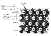
- the Na 4 Co (3-x) M x (PO 4) 2 P 2 crystal structure of O 7 (space group Pn2 1 a), is a view from the a-axis direction.
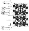
- the Na 4 Co (3-x) M x (PO 4) 2 P 2 crystal structure of O 7 (space group Pn2 1 a), is a view from the b-axis direction.
- It is a cross-sectional schematic diagram which shows one example of a sodium battery. 6 is a graph showing discharge capacities of secondary batteries including positive electrode active materials of Examples 1 to 8 and Comparative Examples 1 and 2.
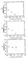
- 6 is a graph showing discharge capacities of secondary batteries including positive electrode active materials of Examples 9 to 13 and Comparative Examples 1 and 3.
- 7 is a graph showing the discharge capacity of a secondary battery including the positive electrode active material of Comparative Examples 1 and 4 to 6.
- 6 is a graph showing the discharge capacity of a secondary battery including the positive electrode active materials of Comparative Examples 1 and 7 to 9.
- 7 is a graph showing the discharge capacity of a secondary battery including the positive electrode active material of Comparative Examples 1 and 10 to 12.
- 6 is a graph showing the discharge capacity of a secondary battery including the positive electrode active materials of Comparative Examples 1 and 13 to 15.
- 6 is a graph showing discharge capacities of secondary batteries containing positive electrode active materials of Examples 14 to 19 and Comparative Examples 1 and 16.
- 6 is a graph showing the discharge capacity of a secondary battery including the positive electrode active material of Comparative Examples 1 and 18 to 20.
- 7 is a graph showing discharge capacities of secondary batteries containing positive electrode active materials of Comparative Examples 1 and 21-23.
- positive electrode active material for sodium battery of the present invention
- sodium battery the positive electrode active material for sodium battery of the present invention
- the positive electrode active material for a sodium battery of the present invention is represented by the general formula Na 4 Co (3-x) M x (PO 4 ) 2 P 2 O 7, where M is any one of Fe, Cr, Mn, and Al. And x is 0.015 ⁇ x ⁇ 0.21 when M is Fe, and 0.03 ⁇ x ⁇ 0.18 when M is Cr. In the case of Mn, 0.006 ⁇ x ⁇ 0.24, and in the case where M is Al, 0.03 ⁇ x ⁇ 0.06.
- the present invention includes the following first to fourth positive electrode active materials.
- the second positive electrode active material for a sodium battery is represented by the general formula Na 4 Co (3-x) Cr x (PO 4 ) 2 P 2 O 7 (wherein 0.03 ⁇ x ⁇ 0.18) It is characterized by.
- the fourth positive electrode active material for a sodium battery is represented by the general formula Na 4 Co (3-x) Al x (PO 4 ) 2 P 2 O 7 (wherein 0.03 ⁇ x ⁇ 0.06). It is characterized by that.
- the compound represented by Na 4 Co 3 (PO 4 ) 2 P 2 O 7 can be used as a positive electrode active material of a sodium battery and can operate in a high potential region.
- Na 4 Co 3 (PO 4 ) 2 P 2 O 7 and Na 4 Co 3 (PO 4 ) 2 P 2 O 7 that are actually synthesized and evaluated in Patent Document 1.
- a part of Co is replaced with at least one of Mn and Ni, a problem has been found that the discharge capacity is low.
- the discharge capacity of Na 4 Co 3 (PO 4) 2 P 2 O 7 is about 90 mAh / g (paragraph 0092, FIG. 11).
- the discharge capacity of a part of Co in Na 4 Co 3 (PO 4 ) 2 P 2 O 7 is replaced by Mn. In the range of 0.3 to 0.9, it is 90 to 103 mAh / g (paragraph 0101, FIG.
- the comparative example described later in this specification is based on the substitution amount of Ni x in which part of Co in Na 4 Co 3 (PO 4 ) 2 P 2 O 7 is substituted with Ni. This indicates that the discharge capacity in the case of 0.03 to 0.15 does not exceed 100 mAh / g.
- One of the factors that cause a low discharge capacity of the positive electrode active material such as Na 4 Co 3 (PO 4 ) 2 P 2 O 7 is that a part of Na + desorbed at the time of charging is not inserted at the time of discharging, so Is generated. The reason why a part of Na + desorbed at the time of charging does not return at the time of discharging is presumed to be due to the low diffusion of Na + inside the positive electrode active material at the discharge end.
- the present inventor has studied to increase the discharge capacity (reversible capacity).
- a part of Co in Na 4 Co 3 (PO 4 ) 2 P 2 O 7 is a specific metal element M that can be trivalent
- a part of Co is replaced with Fe at a ratio of 0.015 ⁇ x ⁇ 0.21, or a part of Co is Cr and 0.03 ⁇ x ⁇ 0.18.
- a part of Co is replaced by Mn and a ratio of 0.006 ⁇ x ⁇ 0.24, or a part of Co is Al and 0.03 ⁇ x ⁇ 0.
- a positive electrode active material for a sodium battery having a discharge capacity larger than that of Na 4 Co 3 (PO 4 ) 2 P 2 O 7 can be obtained by substitution at a ratio of 06.
- a large discharge capacity significantly exceeding 100 mAh / g can be realized.
- the increase in the discharge capacity of the positive electrode active material greatly contributes to the improvement of the charge / discharge efficiency, and also increases the operation time of the battery in one charge, such as an increase in the cruising distance of the electric vehicle.
- the positive electrode active material for a sodium battery of the present invention substitutes a part of Co constituting Na 4 Co 3 (PO 4 ) 2 P 2 O 7 with a specific metal (specific metal ion) that can be trivalent,
- a common effect of achieving a discharge capacity higher than that of Na 4 Co 3 (PO 4 ) 2 P 2 O 7 is achieved by a common means of adjusting the amount x to be replaced within an appropriate range.
- the reason why the discharge capacity of the positive electrode active material for sodium batteries of the present invention is higher than that of Na 4 Co 3 (PO 4 ) 2 P 2 O 7 is not clear at this time, but a part (specific amount) of Co is used.
- the reversibility of the crystal structure of the positive electrode active material at the time of discharge is increased, and Na + in the positive electrode active material at the discharge end is increased. It is considered that the diffusibility of the material is improved.
- a metal that can be trivalent such as Fe, Cr, Mn, and Al
- the reversibility of the crystal structure of the positive electrode active material at the time of discharge is increased, and Na + in the positive electrode active material at the discharge end is increased. It is considered that the diffusibility of the material is improved.
- a part of Co constituting Na 4 Co 3 (PO 4 ) 2 P 2 O 7 is replaced with a divalent and stable metal (metal ion) such as Mg or Ca
- the discharge capacity cannot be improved.
- the metal can be trivalent even if it is replaced with a metal other than the specific metal, for example, a metal such as Cu, Zn, Ni, or Zr, the discharge capacity cannot be improved. (See the comparative example described later).
- the positive electrode active material for the first sodium cell formula Na 4 Co (3-x) Fe x (PO 4) 2 P 2 O 7 ( where, 0.015 ⁇ x ⁇ 0.21) those represented by It is.
- x representing the amount of substitution of Co by Fe may be in the range of 0.015 ⁇ x ⁇ 0.21, but higher discharge capacity and higher charge / discharge efficiency are obtained. Since it is obtained, it is preferable that 0.03 ⁇ x. From the same viewpoint, x ⁇ 0.09 is preferable, and x ⁇ 0.06 is particularly preferable.
- the first positive electrode active material for a sodium battery preferably has a crystal structure belonging to the space group Pn2 1 a.
- FIGS. 1 to 3 show the crystal structure (Na 4 Co (3-x) M x (PO 4 ) 2 P 2 O 7 ) belonging to the space group Pn2 1 a as seen from the a-axis direction (FIG. 1), The figure seen from the b-axis direction (FIG. 2) and the figure seen from the c-axis direction (FIG. 3) are shown.
- M is a metal substituted with a part of Co.
- Fe is It is.
- the occupancy ratio of Co ions and M ions, and the occupancy ratio of CoO 6 octahedron and MO 6 octahedron vary depending on the value of the substitution amount x of Co by M. . That is, the Co ion occupancy and the CoO 6 octahedron occupancy are (3-x) / 3 ⁇ 100%, and the M ion occupancy and the MO 6 octahedron occupancy are x / 3 ⁇ 100%. is there.
- the occupancy of Co ions and the occupancy of CoO 6 octahedron are (3-x) / 3 ⁇ 100% (where 0.015 ⁇ x ⁇ 0.21)
- the occupation ratio of M ions, that is, Fe ions, and the occupation ratio of MO 6 octahedron, that is, FeO 6 octahedron is x / 3 ⁇ 100% (where 0.015 ⁇ x ⁇ 0.21).
- the first positive electrode active material for a sodium battery preferably has a crystal structure belonging to the space group Pn2 1 a.
- the crystal structure belonging to space group Pn2 1 a is the same as the crystal structure belonging to the space group Pna2 1 that by changing the lattice axis is denoted the symmetry of the crystal structure.
- it can confirm by X-ray diffraction that the positive electrode active material for sodium batteries has a crystal structure which belongs to space group Pn2 1 a.
- the second positive electrode active material for a sodium battery is represented by the general formula Na 4 Co (3-x) Cr x (PO 4 ) 2 P 2 O 7 (wherein 0.03 ⁇ x ⁇ 0.18) It is.
- x representing the amount of substitution of Co by Cr may be in the range of 0.03 ⁇ x ⁇ 0.18, but has a higher discharge capacity and higher charge / discharge efficiency. From the viewpoint of being obtained, 0.09 ⁇ x is preferable, and 0.12 ⁇ x is particularly preferable. From the same viewpoint, it is preferable that x ⁇ 0.15.
- the second positive electrode active material for a sodium battery preferably has a crystal structure belonging to the space group Pn2 1 a for the same reason as the first positive electrode active material for a sodium battery. 1 to 3, the crystal structure of the second positive electrode active material for a sodium battery having a crystal structure belonging to the space group Pn2 1 a is shown when M is Cr. In addition, with respect to the occupation ratios shown in FIGS.
- the occupation ratio of Co ions and the occupation of CoO 6 octahedron is (3-x) / 3 ⁇ 100% (where 0.03 ⁇ x ⁇ 0.18), and the Cr ion occupancy and CrO 6 octahedron occupancy are x / 3 ⁇ 100% ( In the formula, 0.03 ⁇ x ⁇ 0.18).
- the third positive electrode active material for a sodium battery is represented by the general formula Na 4 Co (3-x) Mn x (PO 4 ) 2 P 2 O 7 (where 0.006 ⁇ x ⁇ 0.24) It is.
- x representing the substitution amount of Co by Mn may be in the range of 0.006 ⁇ x ⁇ 0.24, but higher discharge capacity and higher charge / discharge efficiency are obtained. Since it is obtained, it is preferable that 0.03 ⁇ x. From the same viewpoint, it is preferable that x ⁇ 0.15.
- the positive electrode active material for the third sodium batteries for the same reason as the positive electrode active material for a first sodium battery, it is preferable to have a crystal structure belonging to space group Pn2 1 a.
- 1 to 3 show the crystal structure of the second positive electrode active material for a sodium battery having a crystal structure belonging to the space group Pn2 1 a when M is Mn.
- the occupation ratio of Co ions and the occupation of CoO 6 octahedron is (3-x) / 3 ⁇ 100% (where 0.006 ⁇ x ⁇ 0.24), and the Mn ion occupancy and the MnO 6 octahedron occupancy are x / 3 ⁇ 100% ( In the formula, 0.006 ⁇ x ⁇ 0.24).
- the fourth positive electrode active material for a sodium battery is represented by the general formula Na 4 Co (3-x) Al x (PO 4 ) 2 P 2 O 7 (wherein 0.03 ⁇ x ⁇ 0.06) It is.
- x representing the amount of substitution of Co by Al may be in the range of 0.03 ⁇ x ⁇ 0.06.
- the fourth sodium battery positive electrode active material preferably has a crystal structure belonging to the space group Pn2 1 a for the same reason as the first sodium battery positive electrode active material.
- FIGS. 1 to 3 show the crystal structure of the fourth positive electrode active material for a sodium battery having a crystal structure belonging to the space group Pn2 1 a when M is Al. In addition, with respect to the occupation ratios shown in FIGS.
- the occupation ratio of Co ions and the occupation of CoO 6 octahedron The rate is (3-x) / 3 ⁇ 100% (where 0.03 ⁇ x ⁇ 0.06), and the Al ion occupancy and the AlO 6 octahedron occupancy are x / 3 ⁇ 100% ( In the formula, 0.03 ⁇ x ⁇ 0.06).
- the positive electrode active material for a sodium battery of the present invention is preferably in the form of particles, and Na + diffusibility inside the positive electrode active material particles is improved.
- the particles have an average particle size of 10 ⁇ m or less, more preferably 3 ⁇ m or less.
- the average particle size is usually preferably 10 nm or more.
- the average particle diameter of the positive electrode active material for sodium batteries can be measured by observing with a scanning electron microscope (SEM) and a transmission electron microscope (TEM).
- the positive electrode active material for sodium batteries of the present invention can be produced, for example, by the following method. That is, first, a Na-containing compound that is a Na source, a Co-containing compound that is a Co source, and a substitution element-containing compound that is a substitution element source (Fe-containing compound, Cr-containing compound, Mn-containing compound, Al-containing compound, etc.) A P-containing compound as a P source is dissolved in an acidic solution, and after adding a gelling agent, the gel is prepared by heating to volatilize water. Next, the obtained gel is baked in an air atmosphere.
- any compound that can be dissolved in an acidic solution may be used.
- Each compound may be used individually by 1 type, or may be used in combination of 2 or more type.
- one compound may contain 2 or more types of Na, Co, a substituted element, and P.
- examples of the Na-containing compound include Na 4 P 2 O 7 , Na 2 CO 3 , Na 2 O, Na 2 O 2 , CH 3 COONa, and hydrates thereof.
- examples of the Co-containing compound include CoCO 3 , (CH 3 COO) 2 Co, Co 2 O 3, and hydrates thereof.
- examples of the P-containing compound include NH 4 H 2 PO 4 , (NH 4 ) 2 HPO 4 , and H 3 PO 4 .
- Examples of the substitution element-containing compound include Fe (NO 3 ) 3 , FeC 2 O 4 , (CH 3 COO) 3 Fe, and hydrates thereof.
- Examples of the Cr-containing compound include Cr (NO 3 ) 3 , CrO 3 and hydrates thereof.
- Examples of the Mn-containing compound include (CH 3 COO) 3 Mn, Mn (NO 3 ) 2 , MnCO 3 , MnO, and hydrates thereof.
- Examples of the Al-containing compound include Al (NO 3 ) 3 , (CH 3 COO) 3 Al, Al (OH) 3 , Al 2 O 3, and hydrates thereof.
- the mixing ratio of the Na-containing compound, Co-containing compound, substitution element-containing compound, and P-containing compound may be appropriately set according to the stoichiometric ratio of each element in the positive electrode active material to be synthesized.
- the ratio of Fe and P mol ratio
- Each compound may be mixed so that: 3: x: x: 4.
- Each compound may be mixed so that: 3: x: x: 4.
- the ratio (mol ratio) of Na, Co, Al, and P in the gel is Na: Co: Al: P.
- gelling agent examples include glycolic acid.
- an acidic solution examples include nitric acid aqueous solution etc. are mentioned, for example.
- the heating temperature at the time of gel preparation is not particularly limited as long as the above-mentioned compounds can be dissolved in an acidic solution to prepare a gel, and can be set to 60 to 120 ° C., for example.
- the firing temperature of the gel can be, for example, 500 to 800 ° C., and preferably 600 to 750 ° C.
- the firing time is not particularly limited, but can be, for example, 1 to 100 hours.
- the air atmosphere at the time of gel baking means an oxygen-containing gas atmosphere.
- the positive electrode active material obtained after firing is preferably fired in an inert atmosphere after being kneaded with conductive carbon particles.
- the positive electrode active material can be made fine by kneading with the conductive carbon particles.
- the crystallinity of the positive electrode active material may decrease due to kneading with conductive carbon particles, it is possible to improve the decreased crystallinity of the positive electrode active material by firing in an inert atmosphere after kneading. It is.
- the conductive carbon particles act as a conductive additive in the positive electrode, it can be used as a material constituting the positive electrode together with the positive electrode active material.
- the conductive carbon particle is not particularly limited as long as it is a carbon material having electronic conductivity, and examples thereof include acetylene black, graphite, ketjen black, carbon nanotube, and carbon nanofiber.
- the ratio of the positive electrode active material and the conductive carbon particles to be kneaded is not particularly limited, but is preferably within the range of the ratio of the positive electrode active material and the conductive material in the positive electrode active material layer.
- the conductive carbon particles are preferably 1 part by weight or more, particularly 3 parts by weight or more with respect to 100 parts by weight of the positive electrode active material, from the viewpoint of energy density.
- the conductive carbon particles are preferably 40 parts by weight or less, particularly preferably 30 parts by weight or less with respect to 100 parts by weight of the positive electrode active material.
- the method for kneading the positive electrode active material and the conductive carbon particles is not particularly limited, and examples thereof include a bead mill, a ball mill, and a hand mill.
- the positive electrode active material provided by the present invention can be suitably used as a positive electrode active material for sodium batteries.
- the sodium battery may be either a primary battery or a secondary battery, but is particularly useful as a secondary battery because the positive electrode active material of the present invention is excellent in reversibility during charging.
- a sodium battery using the positive electrode active material provided by the present invention will be described taking a sodium secondary battery as an example.
- FIG. 4 is a schematic cross-sectional view showing one embodiment of a sodium secondary battery.
- the sodium secondary battery 8 usually has a structure in which the electrolyte layer 3 is interposed between the negative electrode 1 and the positive electrode 2.
- the negative electrode 1 includes a negative electrode active material layer 4 containing a negative electrode active material, and a negative electrode current collector 5 that collects current from the negative electrode active material layer 4.
- the positive electrode 2 includes a positive electrode active material layer 6 containing a positive electrode active material and a positive electrode current collector 7 that collects current from the positive electrode active material layer 6.
- Each configuration will be described below.
- the positive electrode contains a positive electrode active material capable of releasing and capturing sodium ions.
- the positive electrode usually has a positive electrode active material layer containing at least a positive electrode active material, and further includes a positive electrode current collector that collects the positive electrode active material layer as necessary.
- the positive electrode includes the positive electrode active material of the present invention described above.
- the positive electrode includes a positive electrode active material layer containing the positive electrode active material of the present invention. Since the positive electrode active material has been described in the above section “Positive electrode active material for sodium battery”, description thereof is omitted here.
- the positive electrode active material layer may contain only the positive electrode active material, but may contain a binder, a conductive material, an electrolyte and the like in addition to the positive electrode active material.
- a positive electrode active material layer containing only the positive electrode active material can be obtained.
- the positive electrode active material is particulate, a positive electrode active material layer containing a binder in addition to the positive electrode active material can be obtained.
- the content of the positive electrode active material in the positive electrode active material layer is not particularly limited, but is preferably in the range of 60 to 98 parts by weight when the weight of the positive electrode active material layer is 100.
- binder examples include polyvinylidene fluoride (PVdF), polytetrafluoroethylene (PTFE), styrene butadiene rubber (SBR), and the like.
- the content of the binder in the positive electrode active material layer is not particularly limited, but is preferably in the range of 1 to 20 parts by weight when the weight of the positive electrode active material layer is 100.
- the conductive material include carbon materials such as carbon black, activated carbon, carbon carbon fiber (eg, carbon nanotube, carbon nanofiber, etc.), graphite, and the like.
- the content of the conductive material in the positive electrode active material layer is not particularly limited, but is preferably in the range of 1 to 20 parts by weight when the weight of the positive electrode active material layer is 100.
- the negative electrode contains a negative electrode active material capable of releasing and capturing sodium ions.
- the negative electrode usually has a negative electrode active material layer containing at least a negative electrode active material, and further includes a negative electrode current collector that collects current from the negative electrode active material layer as necessary.
- the negative electrode active material examples include hard carbon, Na metal, tin, and the like.
- the negative electrode active material layer may contain only the negative electrode active material, but in addition to the negative electrode active material, it contains a conductive material, a binder, an electrolyte, and the like. There may be.
- the electroconductive material and binder in a negative electrode active material since the material similar to a positive electrode active material layer can be used, description here is abbreviate
- the positive electrode active material layer and the negative electrode active material layer can be prepared by, for example, slurry containing each material by any coating method such as a dip coating method, a spray coating method, a roll coating method, a doctor blade method, a gravure coating method, and a screen printing method.
- Each electrode active material layer can be formed by coating, drying, and rolling as necessary.
- the positive electrode current collector and the negative electrode current collector are not particularly limited in material, structure, and shape as long as the materials have desired electronic conductivity and do not cause an alloying reaction with sodium ions in the battery environment.
- the material for the positive electrode current collector include metal materials such as stainless steel, nickel, aluminum, iron, titanium, and copper, carbon materials such as carbon fiber and carbon paper, and high electron conductive ceramic materials such as titanium nitride. It is done.
- the battery case may have a function as a positive electrode current collector.
- Examples of the material for the negative electrode current collector include copper, stainless steel, nickel, and aluminum.
- the battery case may have a function as a negative electrode current collector.
- Examples of the shape of the positive electrode current collector and the negative electrode current collector include a plate shape, a foil shape, and a mesh shape.
- the electrolyte layer contains at least an electrolyte that enables conduction of sodium ions between the positive electrode and the negative electrode.
- the electrolyte only needs to have sodium ion conductivity, and examples thereof include an electrolyte, a gel electrolyte obtained by gelling the electrolyte using a polymer, a solid electrolyte, and the like.
- Examples of the electrolytic solution having sodium ion conductivity include an aqueous electrolytic solution in which a sodium salt is dissolved in an aqueous solvent, and a nonaqueous electrolytic solution in which a sodium salt is dissolved in a nonaqueous solvent.
- the non-aqueous solvent is not particularly limited, and examples thereof include cyclic carbonates such as propylene carbonate (PC), ethylene carbonate (EC), and fluoroethylene carbonate (FEC), cyclic esters such as ⁇ -butyrolactone (GBL), and dimethyl carbonate. Examples thereof include chain carbonates such as (DMC), diethyl carbonate (DEC), and ethyl methyl carbonate (EMC). These nonaqueous solvents may be used alone or in combination of two or more. Further, a nitrile compound in which a CN group is bonded to the end of the chain saturated hydrocarbon compound may be used by mixing with a non-aqueous solvent.
- cyclic carbonates such as propylene carbonate (PC), ethylene carbonate (EC), and fluoroethylene carbonate (FEC)
- cyclic esters such as ⁇ -butyrolactone (GBL)
- dimethyl carbonate examples thereof include chain carbonates such as (DMC), diethyl carbonate (
- nitrile compound By adding the nitrile compound to the non-aqueous electrolyte, a stable non-aqueous electrolyte that does not decompose can be obtained even in a high potential region where the positive electrode active material for a sodium battery of the present invention operates.
- the sodium salt is not particularly limited, for example, NaPF 6, NaBF 4, NaClO 4, NaCF 3 SO 3, (CF 3 SO 2) 2 NNa, NaN (FSO 2), NaC (CF 3 SO 2) 3 , etc. Is mentioned. These sodium salts may be used individually by 1 type, and may be used in combination of 2 or more type. NaPF 6 which is stable even in a high potential region is particularly preferable. In the nonaqueous electrolytic solution, the concentration of the sodium salt is not particularly limited.
- the non-aqueous electrolyte can be used after adding a polymer to gel.
- the gelation method of the non-aqueous electrolyte include, for example, a polymer such as polyethylene oxide (PEO), polyacrylonitrile (PAN), polyvinylidene fluoride (PVdF), or polymethyl methacrylate (PMMA). The method of adding is mentioned.
- the electrolyte When an electrolytic solution is used as the electrolyte, it is possible to ensure insulation between the positive electrode and the negative electrode by disposing a separator that is an insulating porous body between the positive electrode and the negative electrode and impregnating the separator with the electrolytic solution.
- a separator examples include porous membranes such as polyethylene porous membrane and polypropylene porous membrane; and nonwoven fabrics such as resin nonwoven fabric and glass fiber nonwoven fabric.
- a battery case that accommodates the negative electrode, the electrolyte layer, and the positive electrode for example, a battery case having a general shape such as a coin shape, a flat plate shape, a cylindrical shape, or a laminate shape can be used.
- a separator made of an insulating material between the positive electrode and the negative electrode can be provided. Examples of such a separator include porous membranes such as polyethylene porous membrane and polypropylene porous membrane; and nonwoven fabrics such as resin nonwoven fabric and glass fiber nonwoven fabric.
- the current collector of each electrode can be provided with a terminal serving as a connection portion with the outside.
- the obtained positive electrode active materials (Na 4 Co (3-x) Fe x (PO 4 ) 2 P 2 O 7 ) of Examples 1 to 8 were analyzed by an X-ray diffractometer (XRD).
- XRD X-ray diffractometer
- the cathode active material obtained in Example 1 ⁇ 8 (Na 4 Co ( 3-x) Fe x (PO 4) 2 P 2 O 7) is, to have a crystal structure belonging to space group Pn2 1 a Was confirmed.
- the breakdown of the conductive carbon weight ratio 20 is the first conductive carbon 15 and the second conductive carbon 5.
- Each slurry was applied onto an aluminum foil (current collector), dried and rolled to produce a positive electrode in which the current collector and the positive electrode active material layer were laminated.
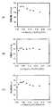
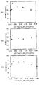
- FIGS. 5A, 5B, and 5C The discharge capacity, charge capacity, and charge / discharge efficiency of the first cycle are shown in FIGS. 5A, 5B, and 5C, respectively.
- the horizontal axis represents x in Na 4 Co (3-x) Fe x (PO 4 ) 2 P 2 O 7 .
- the charge / discharge efficiency was calculated from discharge capacity / charge capacity ⁇ 100%.
- -Potential range Upper limit voltage 4.7V, lower limit voltage 2.0V ⁇ Current density: 34 mA / g ⁇ Temperature: 25 °C
- Examples 1 to 8 in which x in Na 4 Co (3-x) Fe x (PO 4 ) 2 P 2 O 7 is in the range of 0.015 ⁇ x ⁇ 0.21 , Both had higher discharge capacity than Comparative Example 1 where x 0.
- Na 4 Co (3-x ) x in Fe x (PO 4) 2 P 2 O 7 is, 0.03 ⁇ x ⁇ 0.09 in the range of Examples 2-5, especially 0.03 ⁇ Examples 2 to 4 in the range of x ⁇ 0.06 had particularly high discharge capacity and excellent charge / discharge efficiency.
- the charging / discharging efficiency of the comparative example 2 is higher than the comparative example 1, this is because the charging capacity of the comparative example 2 is low.
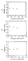
- Examples 9 to 13 in which x in Na 4 Co (3-x) Cr x (PO 4 ) 2 P 2 O 7 is in the range of 0.03 ⁇ x ⁇ 0.18 , Both had higher discharge capacity than Comparative Example 1 where x 0.
- Examples 10 to 13 showed higher charge / discharge efficiency than Comparative Example 1.
- Examples 11 to 12 in the range of x ⁇ 0.15 had particularly high discharge capacity and excellent charge / discharge efficiency.
- the charge / discharge efficiency of Comparative Example 3 is higher than that of Comparative Example 1 and Examples 9 to 13, because the charge capacity of Comparative Example 3 is very low.
- Table 3 also shows the composition of Comparative Example 1. Further, it was confirmed that the positive electrode active materials obtained in Comparative Examples 4 to 6 had a crystal structure belonging to the space group Pn2 1 a.
- Table 4 also shows the composition of Comparative Example 1. It was also confirmed that the positive electrode active materials obtained in Comparative Examples 7 to 9 had a crystal structure belonging to the space group Pn2 1 a.
- Table 6 also shows the composition of Comparative Example 1. It was also confirmed that the positive electrode active materials obtained in Comparative Examples 13 to 15 had a crystal structure belonging to the space group Pn2 1 a.
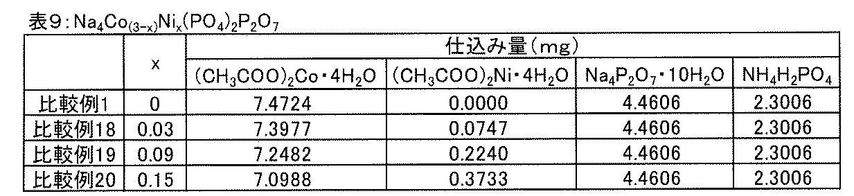
- Table 9 also shows the composition of Comparative Example 1. Further, it was confirmed that the positive electrode active materials obtained in Comparative Examples 18 to 20 had a crystal structure belonging to the space group Pn2 1 a.
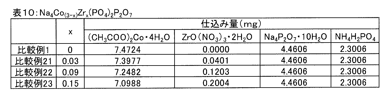
- Table 10 also shows the composition of Comparative Example 1. It was also confirmed that the positive electrode active materials obtained in Comparative Examples 21 to 23 had a crystal structure belonging to the space group Pn2 1 a.
Landscapes
- Chemical & Material Sciences (AREA)
- Organic Chemistry (AREA)
- Inorganic Chemistry (AREA)
- Chemical Kinetics & Catalysis (AREA)
- Electrochemistry (AREA)
- General Chemical & Material Sciences (AREA)
- Engineering & Computer Science (AREA)
- Crystallography & Structural Chemistry (AREA)
- Materials Engineering (AREA)
- Manufacturing & Machinery (AREA)
- Battery Electrode And Active Subsutance (AREA)
- Secondary Cells (AREA)
- Primary Cells (AREA)
Abstract
Description
リチウム電池は、上記したようにエネルギー密度や出力に優れる一方、リチウム電池の需要拡大に伴いリチウムの価格が上昇していることや、リチウムの埋蔵量が限られていること等が、量産や大型化のボトルネックとなっている。
例えば、特許文献1には、一般式NaxMy(AO4)zP2O7で表わされるナトリウム電池用正極活物質であって、前記MがNi、Mn、Coのいずれかであり、その一部がTi、V、Cr、Mn、Fe、Co、Ni、Cu及びZnよりなる群から選ばれる少なくとも1種で置換されていてもよい旨が記載されている。また、特許文献1には、上記一般式で表わされるナトリウム電池用正極活物質において、前記MがCoであって、その一部をMn及びNiの少なくとも一方で置換した正極活物質が合成、評価されている。
本発明によれば、上記一般式で表される化合物群において、Coの一部を、3価となり得る特定の金属Mで置換し、その置換する量xを適切な範囲内に調整することによって、放電容量に優れたナトリウム電池用正極活物質を提供することができる。
本発明のナトリウム電池用正極活物質は、一般式Na4Co(3-x)Mx(PO4)2P2O7で表わされ、前記MはFe、Cr、Mn、Alのいずれかであり、前記xは、前記MがFeの場合は、0.015≦x≦0.21であり、前記MがCrの場合は、0.03≦x≦0.18であり、前記MがMnの場合は、0.006≦x≦0.24であり、前記MがAlの場合は、0.03≦x≦0.06であることを特徴とするものである。
本発明には、次の第一から第四の正極活物質が含まれる。
第一のナトリウム電池用正極活物質は、一般式Na4Co(3-x)Fex(PO4)2P2O7(式中、0.015≦x≦0.21)で表わされることを特徴とするものである。
第二のナトリウム電池用正極活物質は、一般式Na4Co(3-x)Crx(PO4)2P2O7(式中、0.03≦x≦0.18)で表わされることを特徴とするものである。
第三のナトリウム電池用正極活物質は、一般式Na4Co(3-x)Mnx(PO4)2P2O7(式中、0.006≦x≦0.24)で表わされることを特徴とするものである。
また、第四のナトリウム電池用正極活物質は、一般式Na4Co(3-x)Alx(PO4)2P2O7(式中、0.03≦x≦0.06)で表わされることを特徴とするものである。
具体的には、Na4Co3(PO4)2P2O7の放電容量は、特許文献1の実施例3の結果によると、約90mAh/gである(段落0092、図11)。本明細書において後述する比較例の結果も、Na4Co3(PO4)2P2O7、つまり置換量x=0の場合の放電容量は、100mAh/gを超えないことを示している。
また、Na4Co3(PO4)2P2O7のCoの一部がMnで置換されたものの放電容量は、特許文献1の実施例4~8の結果によると、Mnの置換量xが0.3から0.9の範囲において、90~103mAh/gである(段落0101、図13、図14)。本明細書において後述する比較例の結果も、Na4Co3(PO4)2P2O7のCoの一部がMnで置換されたものは、Mnの置換量xが0.3の場合、つまり特許文献1で開示された置換量の場合の放電容量は、約100mAh/gであることを示している。
また、Na4Co3(PO4)2P2O7のCoの一部がMn及びNiで置換されたものの放電容量は、特許文献1の実施例9~12の結果によると、MnとNiの合計置換量Xが0.6から2.0の範囲において、90~95mAh/gである(段落0111、図16)。Niのみで置換した場合に関し、本明細書において後述する比較例は、Na4Co3(PO4)2P2O7のCoの一部がNiで置換されたものは、Niの置換量xが0.03から0.15の場合の放電容量は、100mAh/gを超えないことを示している。
Na4Co3(PO4)2P2O7等の上記正極活物質の放電容量が低い要因の一つとして、充電時に脱離したNa+の一部が放電時に挿入されないために、不可逆容量が発生することが挙げられる。充電時に脱離したNa+の一部が放電時に戻らないのは、放電末端における正極活物質内部のNa+の拡散性が低いためと推察される。
正極活物質の放電容量の増加は、充放電効率の向上に大きく寄与し、また、電気自動車の航続距離の増加等、一回の充電での電池の作動時間の増加をもたらす。
本発明のナトリウム電池用正極活物質の放電容量が、Na4Co3(PO4)2P2O7と比べて高くなる理由は現時点では明らかではないが、Coの一部(特定量)をFe、Cr、Mn、Al等の3価となり得る金属で置換することによって、放電時の正極活物質の結晶構造の可逆性が高くなること、また、放電末端の正極活物質内部でのNa+の拡散性が向上することが、要因として考えられる。
尚、Na4Co3(PO4)2P2O7を構成するCoの一部を、Mg、Ca等の2価で安定な金属(金属イオン)で置換しても、放電容量を向上できないこと、及び、3価となり得る金属であっても、上記特定の金属以外のもの、例えば、Cu、Zn、Ni、Zr等の金属で置換しても、放電容量を向上できないことが、本発明者によって確認されている(後述の比較例参照)。
(第一のナトリウム電池用正極活物質)
第一のナトリウム電池用正極活物質は、一般式Na4Co(3-x)Fex(PO4)2P2O7(式中、0.015≦x≦0.21)で表わされるものである。
第一のナトリウム電池用正極活物質において、FeによるCoの置換量を表すxは、0.015≦x≦0.21の範囲内であればよいが、より高い放電容量及び高い充放電効率が得られることから、0.03≦xであることが好ましい。同様の観点から、x≦0.09であることが好ましく、特にx≦0.06であることが好ましい。
図1~3に空間群Pn21aに帰属する結晶構造(Na4Co(3-x)Mx(PO4)2P2O7)を、a軸方向から見た図(図1)、b軸方向から見た図(図2)、及びc軸方向から見た図(図3)を示す。尚、Na4Co(3-x)Mx(PO4)2P2O7中、Mは、Coの一部と置換された金属であり、第一のナトリウム電池用正極活物質においてはFeである。
図1~3において、Coイオンの占有率及びMイオンの占有率、並びに、CoO6八面体の占有率及びMO6八面体の占有率は、CoのMによる置換量xの値に応じて変わる。
すなわち、Coイオンの占有率及びCoO6八面体の占有率は(3-x)/3×100%であり、Mイオンの占有率及びMO6八面体の占有率はx/3×100%である。
第一のナトリウム電池用正極活物質においては、Coイオンの占有率及びCoO6八面体の占有率は(3-x)/3×100%(式中、0.015≦x≦0.21)であり、MイオンすなわちFeイオンの占有率、及び、MO6八面体すなわちFeO6八面体の占有率は、x/3×100%(式中、0.015≦x≦0.21)である。
以上のような理由から、第一のナトリウム電池用正極活物質は、空間群Pn21aに帰属する結晶構造を有することが好ましい。
尚、空間群Pn21aに帰属する結晶構造は、格子軸を変更して結晶構造の対称性を表記した空間群Pna21に帰属する結晶構造と同じである。
尚、ナトリウム電池用正極活物質が、空間群Pn21aに帰属する結晶構造を有することは、X線回折により確認することができる。
第二のナトリウム電池用正極活物質は、一般式Na4Co(3-x)Crx(PO4)2P2O7(式中、0.03≦x≦0.18)で表わされるものである。
第二のナトリウム電池用正極活物質において、CrによるCoの置換量を表すxは、0.03≦x≦0.18の範囲内であればよいが、より高い放電容量及び高い充放電効率が得られることから、0.09≦xであることが好ましく、特に0.12≦xであることが好ましい。同様の観点から、x≦0.15であることが好ましい。
第三のナトリウム電池用正極活物質は、一般式Na4Co(3-x)Mnx(PO4)2P2O7(式中、0.006≦x≦0.24)で表わされるものである。
第三のナトリウム電池用正極活物質において、MnによるCoの置換量を表すxは、0.006≦x≦0.24の範囲内であればよいが、より高い放電容量及び高い充放電効率が得られることから、0.03≦xであることが好ましい。同様の観点から、x≦0.15であることが好ましい。
第四のナトリウム電池用正極活物質は、一般式Na4Co(3-x)Alx(PO4)2P2O7(式中、0.03≦x≦0.06)で表わされるものである。
第四のナトリウム電池用正極活物質において、AlによるCoの置換量を表すxは、0.03≦x≦0.06の範囲内であればよい。
本発明において、ナトリウム電池用正極活物質の平均粒径は、走査型電子顕微鏡(SEM)、透過型電子顕微鏡(TEM)で観察することにより測定することができる。
Co含有化合物として、例えば、CoCO3、(CH3COO)2Co、Co2O3及びこれらの水和物等が挙げられる。
P含有化合物としては、例えば、NH4H2PO4、(NH4)2HPO4、及びH3PO4等が挙げられる。
ゲルの焼成温度は、例えば、500~800℃とすることができ、好ましくは600~750℃である。焼成時間は特に限定されないが、例えば、1~100時間とすることができる。ゲル焼成時の大気雰囲気とは、酸素含有ガス雰囲気を意味する。
導電性炭素粒子と混練することによって、正極活物質を微粒子化することができる。導電性炭素粒子との混練により、正極活物質の結晶性が低下する場合があるが、混練後、不活性雰囲気下で焼成することによって、正極活物質の低下した結晶性を向上させることが可能である。また、導電性炭素粒子は、正極において導電助剤として作用するため、正極活物質と共に正極を構成する材料として使用可能である。
本発明により提供される正極活物質は、ナトリウム電池の正極活物質として好適に使用することができる。ナトリウム電池は一次電池でも二次電池でもよいが、本発明の正極活物質が充電時の可逆性に優れることから、二次電池として特に有用である。以下、ナトリウム二次電池を例に、本発明により提供される正極活物質を用いたナトリウム電池について説明する。
以下、各構成について説明する。
本発明のナトリウム電池において、正極は、上記にて説明した本発明の正極活物質を含む。典型的には、正極は、本発明の正極活物質を含む正極活物質層を備える。正極活物質については、上記「ナトリウム電池用正極活物質」の項にて説明したため、ここでの説明は省略する。
一方、正極活物質が粒子状である場合は、正極活物質に加えて結着剤を含有する正極活物質層とすることができる。正極活物質層における正極活物質の含有量は特に限定されないが、正極活物質層の重量を100としたときに、60~98重量部の範囲内であることが好ましい。
結着剤としては、例えば、ポリフッ化ビニリデン(PVdF)、ポリテトラフルオロエチレン(PTFE)、スチレンブタジエンゴム(SBR)等が挙げられる。正極活物質層における結着剤の含有量は特に限定されないが、正極活物質層の重量を100としたときに、1~20重量部の範囲内であることが好ましい。
導電性材料としては、例えば、カーボンブラック、活性炭、カーボン炭素繊維(例えばカーボンナノチューブ、カーボンナノファイバー等)、グラファイト等の炭素材料等を挙げることができる。正極活物質層における導電性材料の含有量は特に限定されないが、正極活物質層の重量を100としたときに、1~20重量部の範囲内であることが好ましい。
正極活物質層と同様、負極活物質層は、負極活物質のみを含有するものであってもよいが、負極活物質の他に導電性材料や、結着剤、電解質等を含有するものであってもよい。
負極活物質における導電性材料、結着剤については、正極活物質層と同様の材料を用いることができるため、ここでの説明は省略する。
正極集電体の材料としては、例えば、ステンレス、ニッケル、アルミニウム、鉄、チタン、銅等の金属材料、カーボンファイバー、カーボンペーパー等のカーボン材料、窒化チタン等の高電子伝導性セラミックス材料等が挙げられる。電池ケースが正極集電体としての機能を兼ね備えていてもよい。
負極集電体の材料としては、銅、ステンレス、ニッケル、アルミニウム等が挙げられる。電池ケースが負極集電体としての機能を有していてもよい。
正極集電体及び負極集電体の形状としては、例えば、板状、箔状、メッシュ状等が挙げられる。
電解質としては、ナトリウムイオン伝導性を有していればよく、例えば、電解液、電解液をポリマー等を用いてゲル化したゲル状電解質、固体電解質等が挙げられる。
ナトリウムイオン伝導性を有する電解液としては、例えば、ナトリウム塩を水系溶媒に溶解した水系電解液、ナトリウム塩を非水溶媒に溶解した非水系電解液が挙げられる。
非水系電解液において、ナトリウム塩の濃度は特に限定されない。
正極、電解質層、負極の順番で配置されている積層体を、繰り返し何層も重ねる構造を取る電池の場合には、安全性の観点から、正極および負極の間に、絶縁性材料からなるセパレータを備えることができる。このようなセパレータとしては、例えばポリエチレン多孔膜、ポリプロピレン多孔膜等の多孔膜;および樹脂不織布、ガラス繊維不織布等の不織布等を挙げることができる。
また、各電極の集電体には、それぞれ、外部との接続部となる端子を設けることができる。
(実施例1~8)
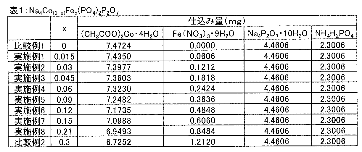
出発原料として、下記表1に示す仕込み量(mg)の(CH3COO)2Co・4H2O、Fe(NO3)3・9H2O、Na4P2O7・10H2O、及びNH4H2PO4を、硝酸水溶液中へ溶解させた。
上記溶液に、ゲル化材として、グリコール酸を添加し、80℃で攪拌した。水分が揮発した後、得られたゲルを、大気雰囲気下、700℃で50時間焼成し、正極活物質(Na4Co(3-x)Fex(PO4)2P2O7)を合成した。
得られた正極活物質の粉末1.0gを、小径化するために、それぞれ、第1の導電性炭素0.2gと混練した。その後、該混練により低下した正極活物質の結晶性を向上させるために、混練物を、アルゴン雰囲気下、700℃で5時間、再焼成した。
また、実施例1~8で得られた正極活物質(Na4Co(3-x)Fex(PO4)2P2O7)が、空間群Pn21aに帰属する結晶構造を有することが確認された。
出発原料の仕込み量(mg)を、表1に示す量に変更したこと以外は、実施例1~8と同様にして正極活物質(Na4Co(3-x)Fex(PO4)2P2O7)を得た。
得られた比較例1~2の正極活物質(Na4Co(3-x)Fex(PO4)2P2O7)をXRDにより分析したところ、それぞれ、Na4Co(3-x)Fex(PO4)2P2O7におけるxが表1に示す値(x=0、0.3)の組成を有することが確認された。また、比較例1~2で得られた正極活物質(Na4Co(3-x)Fex(PO4)2P2O7)が、空間群Pn21aに帰属する結晶構造を有することが確認された。
(実施例1~8、比較例1~2)
<正極の作製>
上記にて得られた実施例1~8の正極活物質と第1の導電性炭素の混練物を焼成したものを、それぞれ、第2の導電性炭素(導電助剤)及びPVdF(結着材)と混合し、N-メチル-2-ピロリドン(分散剤)中に分散させてスラリーを調製した。
尚、スラリーは、正極活物質:導電性炭素(焼成した混練物中の第1の導電性炭素+添加した第2の導電性炭素):PVdF=75:20:5(重量比)となるように、各成分を混合して調製した。すなわち、スラリーにおいて、導電性炭素の重量比20の内訳が、第1の導電性炭素15、第2の導電性炭素5となるようにした。
各スラリーをアルミニウム箔(集電体)上に塗布し、乾燥及び圧延し、集電体と正極活物質層とが積層した正極を作製した。
まず、箔状のナトリウム金属を打ち抜き、負極を作製した。
一方、エチレンカーボネート(EC)とジエチルカーボネート(DEC)とを1:1(体積比)で混合した混合溶媒に、ナトリウム塩(NaPF6)を添加し、ナトリウム塩濃度が1.0mol/dm3の非水溶媒系電解液を調製した。
上記にて作製した各正極と、ポリプロピレン製多孔質膜とポリエチレン製多孔質膜とポリプロピレン製多孔質膜とがこの順序で積層した多孔質膜(セパレータ)、及び上記にて作製した負極を、この順序で積層した。このとき、正極活物質層がセパレータ側となるように正極を積層した。
各積層体のセパレータに上記非水溶媒系電解液を含浸させ、コイン型のナトリウム二次電池を作製した。
上記にて作製した各二次電池を用いて、下記条件にて充放電試験を行った。1サイクル目の放電容量、充電容量及び充放電効率を、図5の(A)、(B)、(C)にそれぞれ示す。尚、図5において、横軸は、Na4Co(3-x)Fex(PO4)2P2O7におけるxである。また、充放電効率は、放電容量/充電容量×100%より算出した。
・電位範囲:上限電圧4.7V、下限電圧2.0V
・電流密度:34mA/g
・温度:25℃
一方、Na4Co(3-x)Fex(PO4)2P2O7において、x=0.3である比較例2は、比較例1よりも低い放電容量を示した。尚、比較例2の充放電効率は比較例1よりも高いが、これは比較例2の充電容量が低いためである。
(実施例9~13、比較例3)
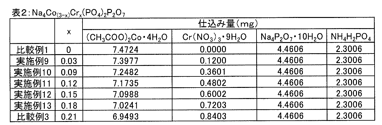
出発原料として、下記表2に示す仕込み量(mg)の(CH3COO)2Co・4H2O、Cr(NO3)3・9H2O、Na4P2O7・10H2O、及びNH4H2PO4を用いたこと以外は、実施例1~8と同様にして正極活物質(Na4Co(3-x)Crx(PO4)2P2O7)を得た。
得られた実施例9~13、比較例3の正極活物質をXRDにより分析したところ、それぞれ、Na4Co(3-x)Crx(PO4)2P2O7におけるxが表2に示す値(実施例9~13:x=0.03、0.09、0.12、0.15、0.18、比較例3:x=0.21)の組成を有することが確認された。尚、表2には、比較例1の組成についても示した。また、実施例9~13、比較例3で得られた正極活物質が、空間群Pn21aに帰属する結晶構造を有することが確認された。
(実施例9~13、比較例3)
実施例1~8及び比較例1~2と同様にして、正極、ナトリウム二次電池を作製し、充放電試験を行った。1サイクル目の放電容量、充電容量及び充放電効率を、図6の(A)、(B)、(C)にそれぞれ示す。尚、図6において、横軸は、Na4Co(3-x)Crx(PO4)2P2O7におけるxであり、図6には比較例1の結果も示した。
図6に示すように、Na4Co(3-x)Crx(PO4)2P2O7におけるxが、0.03≦x≦0.18の範囲内である実施例9~13は、いずれも、x=0である比較例1と比べて、高い放電容量を有していた。また、実施例10~13は、比較例1よりも高い充放電効率を示した。中でも、Na4Co(3-x)Crx(PO4)2P2O7におけるxが、0.12≦x≦0.18の範囲内である実施例11~13、特に0.12≦x≦0.15の範囲内である実施例11~12は、特に高い放電容量を有すると共に充放電効率にも優れていた。
一方、Na4Co(3-x)Crx(PO4)2P2O7において、x=0.21である比較例3は、比較例1よりも大幅に低い放電容量を示した。尚、比較例3の充放電効率は比較例1及び実施例9~13よりも高いが、これは比較例3の充電容量が非常に低いためである。
(比較例4~6)
出発原料として、下記表3に示す仕込み量(mg)の(CH3COO)2Co・4H2O、(CH3COO)2Cu・H2O、Na4P2O7・10H2O、及びNH4H2PO4を用いたこと以外は、実施例1~8と同様にして正極活物質(Na4Co(3-x)Cux(PO4)2P2O7)を得た。
得られた比較例4~6の正極活物質をXRDにより分析したところ、それぞれ、Na4Co(3-x)Cux(PO4)2P2O7におけるxが表3に示す値(x=0.03、0.09、0.15)の組成を有することが確認された。尚、表3には、比較例1の組成についても示した。また、比較例4~6で得られた正極活物質が、空間群Pn21aに帰属する結晶構造を有することが確認された。

(比較例4~6)
実施例1~8及び比較例1~2と同様にして、正極、ナトリウム二次電池を作製し、充放電試験を行った。1サイクル目の放電容量、充電容量及び充放電効率を図7の(A)、(B)、(C)にそれぞれに示す。尚、図7において、横軸は、Na4Co(3-x)Cux(PO4)2P2O7におけるxであり、図7には比較例1の結果も示した。
図7に示すように、Na4Co(3-x)Cux(PO4)2P2O7におけるxが、0より大きい(0.03≦x≦0.15)比較例4~6は、いずれも、x=0である比較例1と比べて、低い放電容量を有しており、xの増加に伴い放電容量が低下する傾向を示した。また、充放電効率についても、比較例4~6は、比較例1と比較して、xの増加に伴い低くなる傾向が見られた。
(比較例7~9)
出発原料として、下記表4に示す仕込み量(mg)の(CH3COO)2Co・4H2O、(CH3COO)2Ca・H2O、Na4P2O7・10H2O、及びNH4H2PO4を用いたこと以外は、実施例1~8と同様にして正極活物質(Na4Co(3-x)Cax(PO4)2P2O7)を得た。
得られた比較例7~9の正極活物質をXRDにより分析したところ、それぞれ、Na4Co(3-x)Cax(PO4)2P2O7におけるxが表4に示す値(x=0.03、0.09、0.15)の組成を有することが確認された。尚、表4には、比較例1の組成についても示した。また、比較例7~9で得られた正極活物質が、空間群Pn21aに帰属する結晶構造を有することが確認された。

(比較例7~9)
実施例1~8及び比較例1~2と同様にして、正極、ナトリウム二次電池を作製し、充放電試験を行った。1サイクル目の放電容量、充電容量及び充放電容量を図8の(A)、(B)、(C)にそれぞれ示す。尚、図8において、横軸は、Na4Co3-xCax(PO4)2P2O7におけるxであり、図8には比較例1の結果も示した。
図8に示すように、Na4Co(3-x)Cax(PO4)2P2O7におけるxが、0より大きい(0.03≦x≦0.15)比較例7~9は、いずれも、x=0である比較例1と比べて、低い放電容量を有しており、xの増加に伴い放電容量が低下する傾向を示した。また、充放電効率についても、比較例7~9は、比較例1よりも低かった。
(比較例10~12)
出発原料として、下記表5に示す仕込み量(mg)の(CH3COO)2Co・4H2O、(CH3COO)2Mg・4H2O、Na4P2O7・10H2O、及びNH4H2PO4を用いたこと以外は、実施例1~8と同様にして正極活物質(Na4Co(3-x)Mgx(PO4)2P2O7)を得た。
得られた比較例10~12の正極活物質をXRDにより分析したところ、それぞれ、Na4Co(3-x)Mgx(PO4)2P2O7におけるxが表5に示す値(x=0.03、0.09、0.15)の組成を有することが確認された。尚、表5には、比較例1の組成についても示した。また、比較例10~12で得られた正極活物質が、空間群Pn21aに帰属する結晶構造を有することが確認された。

(比較例10~12)
実施例1~8及び比較例1~2と同様にして、正極、ナトリウム二次電池を作製し、充放電試験を行った。1サイクル目の放電容量、充電容量及び充放電効率を図9の(A)、(B)、(C)にそれぞれ示す。尚、図9において、横軸は、Na4Co(3-x)Mgx(PO4)2P2O7におけるxであり、図9には比較例1の結果も示した。
図9に示すように、Na4Co(3-x)Mgx(PO4)2P2O7におけるxが、0より大きい(0.03≦x≦0.15)比較例10~12は、いずれも、x=0である比較例1と比べて、低い放電容量を有しており、xの増加に伴い放電容量が低下する傾向を示した。また、充放電効率についても、比較例10~12は、比較例1と比較して、xの増加に伴い低くなる傾向が見られた。
(比較例13~15)
出発原料として、下記表6に示す仕込み量(mg)の(CH3COO)2Co・4H2O、(CH3COO)2Zn・2H2O、Na4P2O7・10H2O、及びNH4H2PO4を用いたこと以外は、実施例1~8と同様にして正極活物質(Na4Co(3-x)Mgx(PO4)2P2O7)を得た。
得られた比較例13~15の正極活物質をXRDにより分析したところ、それぞれ、Na4Co(3-x)Znx(PO4)2P2O7におけるxが表6に示す値(x=0.03、0.09、0.15)の組成を有することが確認された。尚、表6には、比較例1の組成についても示した。また、比較例13~15で得られた正極活物質が、空間群Pn21aに帰属する結晶構造を有することが確認された。

(比較例13~15)
実施例1~8及び比較例1~2と同様にして、正極、ナトリウム二次電池を作製し、充放電試験を行った。1サイクル目の放電容量、充電容量及び充放電効率を図10の(A)、(B)、(C)にそれぞれ示す。尚、図10において、横軸は、Na4Co(3-x)Znx(PO4)2P2O7におけるxであり、図10には比較例1の結果も示した。
図10に示すように、Na4Co(3-x)Znx(PO4)2P2O7におけるxが、0より大きい(0.03≦x≦0.15)比較例13~15は、いずれも、x=0である比較例1と比べて、低い放電容量を有しており、xの増加に伴い放電容量が低下する傾向を示した。また、充放電効率についても、比較例13~15は、比較例1よりも低かった。
(実施例14~19、比較例16)
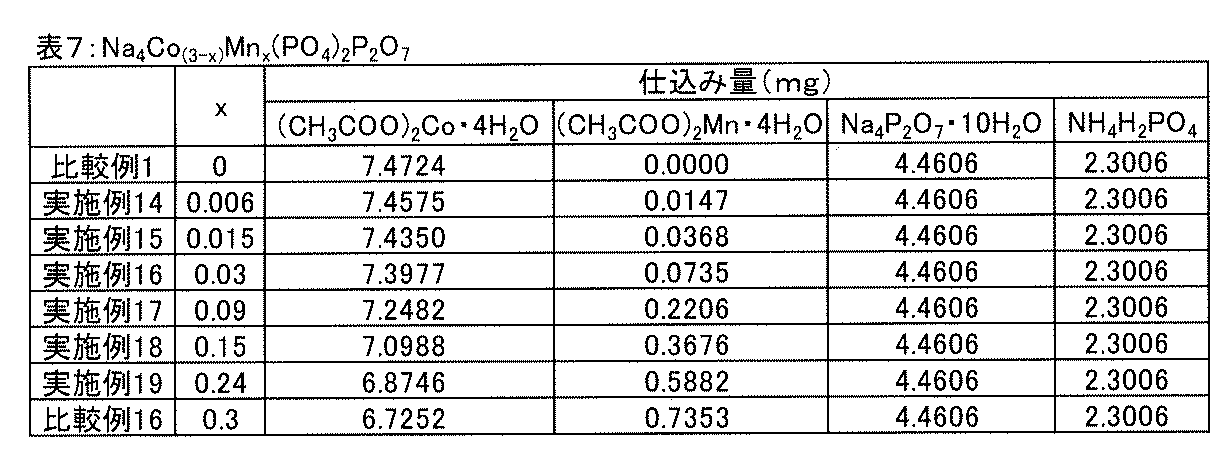
出発原料として、下記表7に示す仕込み量(mg)の(CH3COO)2Co・4H2O、(CH3COO)2Mn・4H2O、Na4P2O7・10H2O、及びNH4H2PO4を用いたこと以外は、実施例1~8と同様にして正極活物質(Na4Co(3-x)Mnx(PO4)2P2O7)を得た。
得られた実施例14~19、比較例16の正極活物質をXRDにより分析したところ、それぞれ、Na4Co(3-x)Mnx(PO4)2P2O7におけるxが表7に示す値(実施例14~19:x=0.006、0.015、0.03、0.09、0.15、0.24、比較例16:x=0.3)の組成を有することが確認された。尚、表7には、比較例1の組成についても示した。また、実施例14~19、比較例16で得られた正極活物質が、空間群Pn21aに帰属する結晶構造を有することが確認された。
(実施例14~19、比較例16)
実施例1~8及び比較例1~2と同様にして、正極、ナトリウム二次電池を作製し、充放電試験を行った。1サイクル目の放電容量、充電容量及び充放電効率を、図11の(A)、(B)、(C)にそれぞれ示す。尚、図11において、横軸は、Na4Co(3-x)Mnx(PO4)2P2O7におけるxであり、図11には比較例1の結果も示した。
図11に示すように、Na4Co(3-x)Mnx(PO4)2P2O7におけるxが、0.006≦x≦0.24の範囲内である実施例14~19は、いずれも、x=0である比較例1と比べて、高い放電容量を有していた。また、実施例14~19は、比較例1よりも高い充放電効率を示した。中でも、Na4Co(3-x)Mnx(PO4)2P2O7におけるxが、0.03≦x≦0.15の範囲内である実施例16~18は、特に高い放電容量を有すると共に充放電効率にも優れていた。
一方、Na4Co(3-x)Mnx(PO4)2P2O7において、x=0.3である比較例16は、比較例1よりも低い放電容量を示した。
(実施例20、21、比較例17)
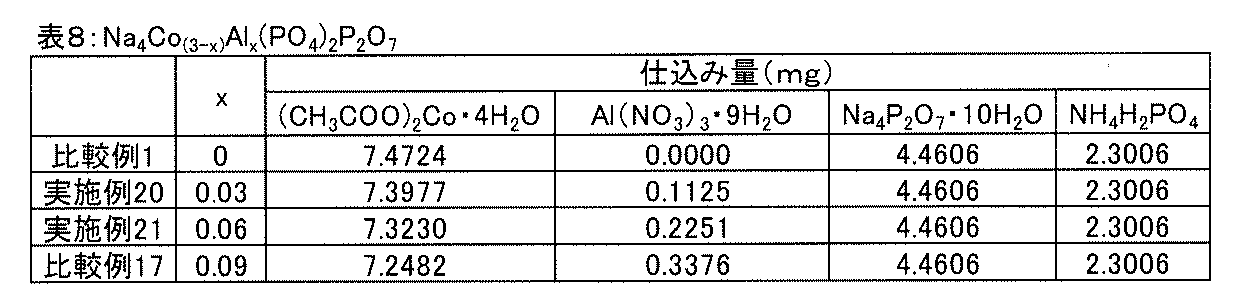
出発原料として、下記表8に示す仕込み量(mg)の(CH3COO)2Co・4H2O、Al(NO3)3・9H2O、Na4P2O7・10H2O、及びNH4H2PO4を用いたこと以外は、実施例1~8と同様にして正極活物質(Na4Co(3-x)Alx(PO4)2P2O7)を得た。
得られた実施例20、21、比較例17の正極活物質をXRDにより分析したところ、それぞれ、Na4Co(3-x)Alx(PO4)2P2O7におけるxが表8に示す値(実施例20、21:x=0.03、0.06、比較例17:x=0.09)の組成を有することが確認された。尚、表8には、比較例1の組成についても示した。また、実施例20、21、比較例17で得られた正極活物質が、空間群Pn21aに帰属する結晶構造を有することが確認された。
(実施例20、21、比較例17)
実施例1~8及び比較例1~2と同様にして、正極、ナトリウム二次電池を作製し、充放電試験を行った。1サイクル目の放電容量、充電容量及び充放電効率を、図12の(A)、(B)、(C)にそれぞれ示す。尚、図12において、横軸は、Na4Co(3-x)Alx(PO4)2P2O7におけるxであり、図12には比較例1の結果も示した。
図12に示すように、Na4Co(3-x)Alx(PO4)2P2O7におけるxが、0.03≦x≦0.06の範囲内である実施例20、21は、いずれも、x=0である比較例1と比べて、高い放電容量を有していた。また、実施例20、21は、比較例1よりも高い充放電効率を示した。
一方、Na4Co(3-x)Alx(PO4)2P2O7において、x=0.09である比較例17は、比較例1よりも低い放電容量を示した。
(比較例18~20)
出発原料として、下記表9に示す仕込み量(mg)の(CH3COO)2Co・4H2O、(CH3COO)2Ni・4H2O、Na4P2O7・10H2O、及びNH4H2PO4を用いたこと以外は、実施例1~8と同様にして正極活物質(Na4Co(3-x)Nix(PO4)2P2O7)を得た。
得られた比較例18~20の正極活物質をXRDにより分析したところ、それぞれ、Na4Co(3-x)Nix(PO4)2P2O7におけるxが表9に示す値(x=0.03、0.09、0.15)の組成を有することが確認された。尚、表9には、比較例1の組成についても示した。また、比較例18~20で得られた正極活物質が、空間群Pn21aに帰属する結晶構造を有することが確認された。
(比較例18~20)
実施例1~8及び比較例1~2と同様にして、正極、ナトリウム二次電池を作製し、充放電試験を行った。1サイクル目の放電容量、充電容量及び充放電効率を図13の(A)、(B)、(C)にそれぞれ示す。尚、図13において、横軸は、Na4Co(3-x)Nix(PO4)2P2O7におけるxであり、図13には比較例1の結果も示した。
図13に示すように、Na4Co(3-x)Nix(PO4)2P2O7におけるxが、0より大きい(0.03≦x≦0.15)比較例18~20は、いずれも、x=0である比較例1と比べて、低い放電容量を有しており、xの増加に伴い放電容量が低下する傾向を示した。
(比較例21~23)
出発原料として、下記表10に示す仕込み量(mg)の(CH3COO)2Co・4H2O、ZrO(NO3)3・2H2O、Na4P2O7・10H2O、及びNH4H2PO4を用いたこと以外は、実施例1~8と同様にして正極活物質(Na4Co(3-x)Zrx(PO4)2P2O7)を得た。
得られた比較例21~23の正極活物質をXRDにより分析したところ、それぞれ、Na4Co(3-x)Zrx(PO4)2P2O7におけるxが表10に示す値(x=0.03、0.09、0.15)の組成を有することが確認された。尚、表10には、比較例1の組成についても示した。また、比較例21~23で得られた正極活物質が、空間群Pn21aに帰属する結晶構造を有することが確認された。
(比較例21~23)
実施例1~8及び比較例1~2と同様にして、正極、ナトリウム二次電池を作製し、充放電試験を行った。1サイクル目の放電容量、充電容量及び充放電効率を図14の(A)、(B)、(C)にそれぞれ示す。尚、図14において、横軸は、Na4Co(3-x)Zrx(PO4)2P2O7におけるxであり、図14には比較例1の結果も示した。
図14に示すように、Na4Co(3-x)Zrx(PO4)2P2O7におけるxが、0より大きい(0.03≦x≦0.15)比較例21~23は、いずれも、x=0である比較例1と比べて、低い放電容量を有しており、xの増加に伴い放電容量が低下する傾向を示した。また、充放電効率についても、比較例21~23は、比較例1よりも低かった。
2…正極
3…電解質層
4…負極活物質層
5…負極集電体
6…正極活物質層
7…正極集電体
8…ナトリウム二次電池
Claims (7)
- 一般式Na4Co(3-x)Mx(PO4)2P2O7で表わされ、
前記MはFe、Cr、Mn、Alのいずれかであり、
前記Xは、前記MがFeの場合は、0.015≦x≦0.21であり、前記MがCrの場合は、0.03≦x≦0.18であり、前記MがMnの場合は、0.006≦x≦0.24であり、前記MがAlの場合は、0.03≦x≦0.06である、
ことを特徴とする、ナトリウム電池用の正極活物質。 - 一般式Na4Co(3-x)Fex(PO4)2P2O7(式中、0.015≦x≦0.21)で表されることを特徴とする、請求項1に記載のナトリウム電池用正極活物質。
- 一般式Na4Co(3-x)Crx(PO4)2P2O7(式中、0.03≦x≦0.18)で表されることを特徴とする、請求項1に記載のナトリウム電池用正極活物質。
- 一般式Na4Co(3-x)Mnx(PO4)2P2O7(式中、0.006≦x≦0.24)で表されることを特徴とする、請求項1に記載のナトリウム電池用正極活物質。
- 一般式Na4Co(3-x)Alx(PO4)2P2O7(式中、0.03≦x≦0.06)で表されることを特徴とする、請求項1に記載のナトリウム電池用正極活物質。
- 空間群Pn21aに帰属する結晶構造を有する、請求項1乃至請求項5に記載のナトリウム電池用正極活物質。
- 請求項1乃至6のいずれか一項に記載のナトリウム電池用正極活物質を含む正極を備えることを特徴とする、ナトリウム電池。
Priority Applications (4)
| Application Number | Priority Date | Filing Date | Title |
|---|---|---|---|
| CN201480057804.3A CN105684198B (zh) | 2013-10-24 | 2014-08-25 | 钠电池用正极活性物质和钠电池 |
| US15/030,091 US9716274B2 (en) | 2013-10-24 | 2014-08-25 | Cathode active material for sodium batteries, and sodium battery |
| GB1606881.9A GB2533536B (en) | 2013-10-24 | 2014-08-25 | Cathode active material for sodium batteries, and sodium battery |
| JP2015543747A JP6172288B2 (ja) | 2013-10-24 | 2014-08-25 | ナトリウム電池用正極活物質及びナトリウム電池 |
Applications Claiming Priority (2)
| Application Number | Priority Date | Filing Date | Title |
|---|---|---|---|
| JP2013-221302 | 2013-10-24 | ||
| JP2013221302 | 2013-10-24 |
Publications (1)
| Publication Number | Publication Date |
|---|---|
| WO2015059998A1 true WO2015059998A1 (ja) | 2015-04-30 |
Family
ID=52992606
Family Applications (1)
| Application Number | Title | Priority Date | Filing Date |
|---|---|---|---|
| PCT/JP2014/072172 Ceased WO2015059998A1 (ja) | 2013-10-24 | 2014-08-25 | ナトリウム電池用正極活物質及びナトリウム電池 |
Country Status (5)
| Country | Link |
|---|---|
| US (1) | US9716274B2 (ja) |
| JP (1) | JP6172288B2 (ja) |
| CN (1) | CN105684198B (ja) |
| GB (1) | GB2533536B (ja) |
| WO (1) | WO2015059998A1 (ja) |
Cited By (2)
| Publication number | Priority date | Publication date | Assignee | Title |
|---|---|---|---|---|
| JP2025537886A (ja) * | 2023-01-16 | 2025-11-20 | 香港時代新能源科技有限公司 | 正極活性材料、及びその製造方法、二次電池、電池モジュール、電池パック並びに電気装置 |
| JP2025539124A (ja) * | 2023-01-16 | 2025-12-03 | 香港時代新能源科技有限公司 | 正極活性材料、及びその製造方法、二次電池、電池モジュール、電池パック並びに電気装置 |
Families Citing this family (9)
| Publication number | Priority date | Publication date | Assignee | Title |
|---|---|---|---|---|
| CN106518742B (zh) | 2011-10-26 | 2020-01-21 | 阿勒根公司 | 作为甲酰肽受体样-1(fprl-1)受体调节剂的n-脲取代的氨基酸的酰胺衍生物 |
| WO2017197406A1 (en) | 2016-05-13 | 2017-11-16 | Quantumscape Corporation | Solid electrolyte separator bonding agent |
| SG11201908691PA (en) | 2017-03-20 | 2019-10-30 | Broad Inst Inc | Compounds and methods for the treatment of parasitic diseases |
| CN107069012B (zh) * | 2017-04-24 | 2020-01-24 | 国网河南省电力公司电力科学研究院 | 中空球形Na4Fe3(PO4)2P2O7/C复合物正极材料及其制备方法 |
| EP3718156A1 (en) * | 2017-11-28 | 2020-10-07 | QuantumScape Corporation | Catholyte management for a solid-state separator |
| CN110137492A (zh) * | 2018-02-08 | 2019-08-16 | 华南理工大学 | 双磷酸锰钠及其合成方法与在钠离子电池中的应用 |
| KR102905859B1 (ko) | 2018-06-06 | 2025-12-31 | 퀀텀스케이프 배터리, 인코포레이티드 | 고체-상태 배터리 |
| CN114361421A (zh) * | 2022-01-08 | 2022-04-15 | 温州大学碳中和技术创新研究院 | 一种聚阴离子型高电压钠离子电池正极材料及其制备方法 |
| CN115810737A (zh) * | 2022-12-29 | 2023-03-17 | 蜂巢能源科技股份有限公司 | 一种钠离子电池正极材料、制备方法、电池及用电设备 |
Citations (2)
| Publication number | Priority date | Publication date | Assignee | Title |
|---|---|---|---|---|
| JP2006523930A (ja) * | 2003-04-08 | 2006-10-19 | ヴァレンス テクノロジー インコーポレーテッド | オリゴリン酸塩をベースとした電極活物質およびその製造方法 |
| WO2013031331A1 (ja) * | 2011-08-29 | 2013-03-07 | トヨタ自動車株式会社 | ナトリウム電池用正極活物質及びその製造方法 |
Family Cites Families (4)
| Publication number | Priority date | Publication date | Assignee | Title |
|---|---|---|---|---|
| GB2495279A (en) * | 2011-09-30 | 2013-04-10 | Faradion Ltd | A condensed polyanion electrode material |
| EP2860800B1 (en) * | 2012-06-12 | 2018-07-25 | Toyota Jidosha Kabushiki Kaisha | Positive electrode material for sodium batteries and method for producing same |
| JP5527385B2 (ja) * | 2012-11-08 | 2014-06-18 | トヨタ自動車株式会社 | 正極活物質およびハイブリッドイオン電池 |
| JP2016039027A (ja) * | 2014-08-07 | 2016-03-22 | トヨタ自動車株式会社 | リチウム二次電池用正極活物質、リチウム二次電池およびリチウム二次電池用正極活物質の製造方法 |
-
2014
- 2014-08-25 CN CN201480057804.3A patent/CN105684198B/zh active Active
- 2014-08-25 US US15/030,091 patent/US9716274B2/en active Active
- 2014-08-25 GB GB1606881.9A patent/GB2533536B/en active Active
- 2014-08-25 JP JP2015543747A patent/JP6172288B2/ja active Active
- 2014-08-25 WO PCT/JP2014/072172 patent/WO2015059998A1/ja not_active Ceased
Patent Citations (2)
| Publication number | Priority date | Publication date | Assignee | Title |
|---|---|---|---|---|
| JP2006523930A (ja) * | 2003-04-08 | 2006-10-19 | ヴァレンス テクノロジー インコーポレーテッド | オリゴリン酸塩をベースとした電極活物質およびその製造方法 |
| WO2013031331A1 (ja) * | 2011-08-29 | 2013-03-07 | トヨタ自動車株式会社 | ナトリウム電池用正極活物質及びその製造方法 |
Non-Patent Citations (2)
| Title |
|---|
| MASAFUMI NOSE ET AL.: "Natoriumu Ion Denchi-yo no Na4Co3-xMx(PO4)2P2O7 [M=Mn,Ni] Seikyoku no Denki Kagaku Tokusei", DAI 54 KAI ABSTRACTS, BATTERY SYMPOSIUM IN JAPAN, 6 October 2013 (2013-10-06), pages 274 * |
| SHINJI NAKANISHI ET AL.: "Na 4M3 (PO4) 2P2O7 Seikyoku o Mochiita Natoriumu Ion Niji Denchi no Kenkyu", DAI 54 KAI ABSTRACTS, BATTERY SYMPOSIUM IN JAPAN, 6 October 2013 (2013-10-06), pages 280 * |
Cited By (2)
| Publication number | Priority date | Publication date | Assignee | Title |
|---|---|---|---|---|
| JP2025537886A (ja) * | 2023-01-16 | 2025-11-20 | 香港時代新能源科技有限公司 | 正極活性材料、及びその製造方法、二次電池、電池モジュール、電池パック並びに電気装置 |
| JP2025539124A (ja) * | 2023-01-16 | 2025-12-03 | 香港時代新能源科技有限公司 | 正極活性材料、及びその製造方法、二次電池、電池モジュール、電池パック並びに電気装置 |
Also Published As
| Publication number | Publication date |
|---|---|
| US20160315321A1 (en) | 2016-10-27 |
| JPWO2015059998A1 (ja) | 2017-03-09 |
| CN105684198A (zh) | 2016-06-15 |
| GB2533536B (en) | 2021-05-19 |
| JP6172288B2 (ja) | 2017-08-02 |
| CN105684198B (zh) | 2018-08-03 |
| GB2533536A (en) | 2016-06-22 |
| US9716274B2 (en) | 2017-07-25 |
Similar Documents
| Publication | Publication Date | Title |
|---|---|---|
| JP5673836B2 (ja) | ナトリウム電池用正極活物質及びその製造方法 | |
| JP6172288B2 (ja) | ナトリウム電池用正極活物質及びナトリウム電池 | |
| CN104364946B (zh) | 钠电池用正极材料及其制造方法 | |
| KR101670327B1 (ko) | 리튬 이온 배터리용 제어된 비가역 용량 손실을 갖는 복합체 캐소드 물질 | |
| JP6273584B2 (ja) | 複合金属酸化物、複合金属酸化物の製造方法およびナトリウム二次電池 | |
| JP2011213587A (ja) | リン酸マンガン鉄リチウム粒子粉末の製造方法、リン酸マンガン鉄リチウム粒子粉末、及び該粒子粉末を用いた非水電解質二次電池 | |
| JP2019003801A (ja) | 非水電解質二次電池用正極及び非水電解質二次電池 | |
| JP2015018621A (ja) | ナトリウム電池用正極活物質およびその製造方法 | |
| JP5401296B2 (ja) | リチウムイオン二次電池用正極及びリチウムイオン二次電池 | |
| JP5910730B2 (ja) | 活物質、およびそれを用いた電極、ならびにリチウムイオン二次電池 | |
| JP2017050204A (ja) | 非水電解質二次電池用正極材料、その製造方法および非水電解質二次電池 | |
| JP2012023006A (ja) | リチウム二次電池用陽極材料及びその製造方法並びにその材料を含むリチウム二次電池 | |
| JP2010238603A (ja) | フッ化リン酸鉄リチウム固溶体正極活物質粉末、及び製造方法、並びにリチウムイオン二次電池 | |
| JP5818086B2 (ja) | 二次電池およびその製造方法 | |
| JP2015026485A (ja) | ナトリウム電池用負極活物質及びナトリウム電池 | |
| JP2016157525A (ja) | 第一級及び/または第二級アミン化合物を含む非水電解質を有する非水電解質二次電池 | |
| JP2023084568A (ja) | 負極活物質、負極活物質の製造方法、負極、電池セル |
Legal Events
| Date | Code | Title | Description |
|---|---|---|---|
| 121 | Ep: the epo has been informed by wipo that ep was designated in this application |
Ref document number: 14855026 Country of ref document: EP Kind code of ref document: A1 |
|
| ENP | Entry into the national phase |
Ref document number: 2015543747 Country of ref document: JP Kind code of ref document: A |
|
| WWE | Wipo information: entry into national phase |
Ref document number: 15030091 Country of ref document: US |
|
| ENP | Entry into the national phase |
Ref document number: 201606881 Country of ref document: GB Kind code of ref document: A Free format text: PCT FILING DATE = 20140825 |
|
| NENP | Non-entry into the national phase |
Ref country code: DE |
|
| 122 | Ep: pct application non-entry in european phase |
Ref document number: 14855026 Country of ref document: EP Kind code of ref document: A1 |