WO2015053034A1 - Système de pile à combustible et procédé permettant de réguler un système de pile à combustible - Google Patents
Système de pile à combustible et procédé permettant de réguler un système de pile à combustible Download PDFInfo
- Publication number
- WO2015053034A1 WO2015053034A1 PCT/JP2014/073961 JP2014073961W WO2015053034A1 WO 2015053034 A1 WO2015053034 A1 WO 2015053034A1 JP 2014073961 W JP2014073961 W JP 2014073961W WO 2015053034 A1 WO2015053034 A1 WO 2015053034A1
- Authority
- WO
- WIPO (PCT)
- Prior art keywords
- fuel cell
- pressure
- current
- pulsation
- cell stack
- Prior art date
Links
Images


Classifications
-
- H—ELECTRICITY
- H01—ELECTRIC ELEMENTS
- H01M—PROCESSES OR MEANS, e.g. BATTERIES, FOR THE DIRECT CONVERSION OF CHEMICAL ENERGY INTO ELECTRICAL ENERGY
- H01M8/00—Fuel cells; Manufacture thereof
- H01M8/04—Auxiliary arrangements, e.g. for control of pressure or for circulation of fluids
- H01M8/04082—Arrangements for control of reactant parameters, e.g. pressure or concentration
-
- H—ELECTRICITY
- H01—ELECTRIC ELEMENTS
- H01M—PROCESSES OR MEANS, e.g. BATTERIES, FOR THE DIRECT CONVERSION OF CHEMICAL ENERGY INTO ELECTRICAL ENERGY
- H01M8/00—Fuel cells; Manufacture thereof
- H01M8/04—Auxiliary arrangements, e.g. for control of pressure or for circulation of fluids
- H01M8/04298—Processes for controlling fuel cells or fuel cell systems
- H01M8/04313—Processes for controlling fuel cells or fuel cell systems characterised by the detection or assessment of variables; characterised by the detection or assessment of failure or abnormal function
- H01M8/04537—Electric variables
- H01M8/04544—Voltage
- H01M8/04559—Voltage of fuel cell stacks
-
- H—ELECTRICITY
- H01—ELECTRIC ELEMENTS
- H01M—PROCESSES OR MEANS, e.g. BATTERIES, FOR THE DIRECT CONVERSION OF CHEMICAL ENERGY INTO ELECTRICAL ENERGY
- H01M8/00—Fuel cells; Manufacture thereof
- H01M8/04—Auxiliary arrangements, e.g. for control of pressure or for circulation of fluids
- H01M8/04082—Arrangements for control of reactant parameters, e.g. pressure or concentration
- H01M8/04089—Arrangements for control of reactant parameters, e.g. pressure or concentration of gaseous reactants
-
- H—ELECTRICITY
- H01—ELECTRIC ELEMENTS
- H01M—PROCESSES OR MEANS, e.g. BATTERIES, FOR THE DIRECT CONVERSION OF CHEMICAL ENERGY INTO ELECTRICAL ENERGY
- H01M8/00—Fuel cells; Manufacture thereof
- H01M8/04—Auxiliary arrangements, e.g. for control of pressure or for circulation of fluids
- H01M8/04291—Arrangements for managing water in solid electrolyte fuel cell systems
-
- H—ELECTRICITY
- H01—ELECTRIC ELEMENTS
- H01M—PROCESSES OR MEANS, e.g. BATTERIES, FOR THE DIRECT CONVERSION OF CHEMICAL ENERGY INTO ELECTRICAL ENERGY
- H01M8/00—Fuel cells; Manufacture thereof
- H01M8/04—Auxiliary arrangements, e.g. for control of pressure or for circulation of fluids
- H01M8/04298—Processes for controlling fuel cells or fuel cell systems
- H01M8/04313—Processes for controlling fuel cells or fuel cell systems characterised by the detection or assessment of variables; characterised by the detection or assessment of failure or abnormal function
- H01M8/04537—Electric variables
- H01M8/04574—Current
- H01M8/04589—Current of fuel cell stacks
-
- H—ELECTRICITY
- H01—ELECTRIC ELEMENTS
- H01M—PROCESSES OR MEANS, e.g. BATTERIES, FOR THE DIRECT CONVERSION OF CHEMICAL ENERGY INTO ELECTRICAL ENERGY
- H01M8/00—Fuel cells; Manufacture thereof
- H01M8/04—Auxiliary arrangements, e.g. for control of pressure or for circulation of fluids
- H01M8/04298—Processes for controlling fuel cells or fuel cell systems
- H01M8/04694—Processes for controlling fuel cells or fuel cell systems characterised by variables to be controlled
- H01M8/04746—Pressure; Flow
- H01M8/04753—Pressure; Flow of fuel cell reactants
-
- H—ELECTRICITY
- H01—ELECTRIC ELEMENTS
- H01M—PROCESSES OR MEANS, e.g. BATTERIES, FOR THE DIRECT CONVERSION OF CHEMICAL ENERGY INTO ELECTRICAL ENERGY
- H01M8/00—Fuel cells; Manufacture thereof
- H01M8/06—Combination of fuel cells with means for production of reactants or for treatment of residues
- H01M8/0662—Treatment of gaseous reactants or gaseous residues, e.g. cleaning
-
- H—ELECTRICITY
- H01—ELECTRIC ELEMENTS
- H01M—PROCESSES OR MEANS, e.g. BATTERIES, FOR THE DIRECT CONVERSION OF CHEMICAL ENERGY INTO ELECTRICAL ENERGY
- H01M2250/00—Fuel cells for particular applications; Specific features of fuel cell system
- H01M2250/20—Fuel cells in motive systems, e.g. vehicle, ship, plane
-
- Y—GENERAL TAGGING OF NEW TECHNOLOGICAL DEVELOPMENTS; GENERAL TAGGING OF CROSS-SECTIONAL TECHNOLOGIES SPANNING OVER SEVERAL SECTIONS OF THE IPC; TECHNICAL SUBJECTS COVERED BY FORMER USPC CROSS-REFERENCE ART COLLECTIONS [XRACs] AND DIGESTS
- Y02—TECHNOLOGIES OR APPLICATIONS FOR MITIGATION OR ADAPTATION AGAINST CLIMATE CHANGE
- Y02E—REDUCTION OF GREENHOUSE GAS [GHG] EMISSIONS, RELATED TO ENERGY GENERATION, TRANSMISSION OR DISTRIBUTION
- Y02E60/00—Enabling technologies; Technologies with a potential or indirect contribution to GHG emissions mitigation
- Y02E60/30—Hydrogen technology
- Y02E60/50—Fuel cells
-
- Y—GENERAL TAGGING OF NEW TECHNOLOGICAL DEVELOPMENTS; GENERAL TAGGING OF CROSS-SECTIONAL TECHNOLOGIES SPANNING OVER SEVERAL SECTIONS OF THE IPC; TECHNICAL SUBJECTS COVERED BY FORMER USPC CROSS-REFERENCE ART COLLECTIONS [XRACs] AND DIGESTS
- Y02—TECHNOLOGIES OR APPLICATIONS FOR MITIGATION OR ADAPTATION AGAINST CLIMATE CHANGE
- Y02T—CLIMATE CHANGE MITIGATION TECHNOLOGIES RELATED TO TRANSPORTATION
- Y02T90/00—Enabling technologies or technologies with a potential or indirect contribution to GHG emissions mitigation
- Y02T90/40—Application of hydrogen technology to transportation, e.g. using fuel cells
Definitions
- the present invention relates to a fuel cell system for estimating a current-voltage characteristic of a fuel cell and a control method for the fuel cell system.
- Some fuel cell systems detect the output voltage while changing the output current of the fuel cell to estimate the current-voltage (IV) characteristics of the fuel cell (see JP2000-357526A).
- impurities such as nitrogen gas and water remaining in the anode gas flow path of the fuel cell are discharged to a buffer tank provided in the anode gas discharge passage.
- impurities present in the power generation region of the fuel cell are reduced, so that a reduction in power generation efficiency of the fuel cell is suppressed.
- Such a fuel cell system may be started in a sub-zero temperature environment.
- the IV characteristic of the fuel cell becomes worse than that during normal operation, it is periodically confirmed whether or not the IV characteristic of the fuel cell has recovered to the IV characteristic that can supply power to the drive motor.
- the anode gas pressure is controlled to increase as the output current of the fuel cell increases. Therefore, when the output current is low, the stress generated in the fuel cell membrane due to the differential pressure between the cathode gas pressure and the anode gas pressure is suppressed.
- the present invention has been made paying attention to such a problem, and suppresses a decrease in estimation accuracy of IV characteristics due to the backflow of impurities while discharging impurities staying in the fuel cell to the volume portion. It is an object to provide a system and a control method for a fuel cell system.
- a fuel cell system that supplies anode gas and cathode gas to a fuel cell and generates power according to a load of the fuel cell includes a volume part that accumulates impurities discharged from the fuel cell.
- the fuel cell system has a pressure control unit for increasing the pressure of the anode gas when the current of the fuel cell is high and the current of the fuel cell when the current of the fuel cell is low.
- An estimation unit that estimates the current-voltage characteristics of the fuel cell based on the current value and voltage value to be acquired, and limits the pressure drop of the anode gas by the pressure control unit when the estimation unit estimates the current-voltage characteristics And a restricting section.
- FIG. 1 is a configuration diagram showing a fuel cell system according to a first embodiment of the present invention.
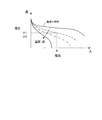
- FIG. 2 is an explanatory diagram showing an estimation method for estimating the IV characteristics of the fuel cell.
- FIG. 3 is a block diagram showing a control unit constituting the controller.
- FIG. 4 is an explanatory diagram illustrating a decrease in output voltage accompanying a decrease in anode gas pressure during IV estimation.
- FIG. 5 is a flowchart showing a limiting method for limiting the pressure drop of the anode gas during IV estimation.
- FIG. 6 is a block diagram showing an anode gas control unit in the second embodiment.
- FIG. 7 is an explanatory diagram showing a limiting method for limiting the pressure drop of the anode gas during IV estimation.
- FIG. 1 is a configuration diagram showing a fuel cell system according to a first embodiment of the present invention.
- FIG. 2 is an explanatory diagram showing an estimation method for estimating the IV characteristics of the fuel cell.
- FIG. 3 is
- FIG. 8 is an explanatory diagram showing the estimation accuracy of the IV characteristics of the fuel cell.
- FIG. 9 is a block diagram showing an anode gas control unit in the third embodiment.
- FIG. 10 is an explanatory diagram showing a limiting method for limiting the pressure drop of the anode gas during IV estimation.
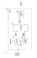
- FIG. 1 is a diagram showing a configuration of a fuel cell system 100 according to the first embodiment of the present invention.
- the fuel cell system 100 is a power supply system that supplies cathode gas and anode gas from the outside to the fuel cell stack 1 and generates power in the fuel cell stack 1 according to the load.
- the fuel cell system 100 supplies the generated power generated by the fuel cell stack 1 to a load such as the drive motor 53.
- the fuel cell system 100 includes a fuel cell stack 1, a cathode gas supply / discharge device 2, an anode gas supply / discharge device 3, a stack cooling device 4, a power system 5, and a controller 6.
- the fuel cell stack 1 is a stacked battery in which several hundred fuel cells (so-called battery cells) are stacked.
- the fuel cell stack 1 generates power by receiving supply of anode gas and cathode gas.
- the fuel cell stack 1 is provided with an anode electrode side output terminal 11 and a cathode electrode side output terminal 12 as terminals for taking out electric power.
- the fuel cell includes an anode electrode (fuel electrode), a cathode electrode (oxidant electrode), and an electrolyte membrane sandwiched between the anode electrode and cathode power.
- an anode gas (fuel gas) containing hydrogen in the anode electrode and a cathode gas (oxidant gas) containing oxygen in the cathode electrode cause an electrochemical reaction in the electrolyte membrane.
- the following electrochemical reaction proceeds in both the anode electrode and the cathode electrode.
- Anode electrode 2H 2 ⁇ 4H + + 4e ⁇ (1)
- Cathode electrode 4H + + 4e ⁇ + O 2 ⁇ 2H 2 O (2)
- the fuel cell stack 1 is supplied with cathode gas by the cathode gas supply / discharge device 2 and supplied with anode gas by the anode gas supply / discharge device 3.
- the cathode gas supply / discharge device 2 is a device that supplies cathode gas to the fuel cell stack 1 and discharges cathode off-gas discharged from the fuel cell stack 1 to the outside air.
- the cathode gas supply / discharge device 2 includes a cathode gas supply passage 21, a filter 22, a cathode compressor 23, a cathode pressure sensor 24, a cathode gas discharge passage 25, and a cathode pressure regulating valve 26.
- the cathode gas supply passage 21 is a passage through which the cathode gas supplied to the fuel cell stack 1 flows. One end of the cathode gas supply passage 21 is connected to the filter 22, and the other end is connected to the cathode gas inlet hole of the fuel cell stack 1.
- the filter 22 removes foreign matters in the cathode gas taken into the cathode gas supply passage 21.
- the cathode compressor 23 is provided in the cathode gas supply passage 21.
- the cathode compressor 23 takes air (outside air) as cathode gas into the cathode gas supply passage 21 through the filter 22 and supplies the air to the fuel cell stack 1.
- the cathode pressure sensor 24 is provided in the cathode gas supply passage 21 downstream of the cathode compressor 23.
- the cathode pressure sensor 24 detects the pressure of the cathode gas supplied to the fuel cell stack 1. The detected pressure detected by the cathode pressure sensor 24 is output to the controller 6.
- the cathode gas discharge passage 25 is a passage through which the cathode off gas discharged from the fuel cell stack 1 flows. One end of the cathode gas discharge passage 25 is connected to the cathode gas outlet hole of the fuel cell stack 1, and the other end is an open end.
- the cathode pressure regulating valve 26 is provided in the cathode gas discharge passage 25.
- the cathode pressure regulating valve 26 is controlled to be opened and closed by the controller 6 and adjusts the pressure of the cathode gas supplied from the cathode compressor 23 to the fuel cell stack 1 to a desired pressure.
- a humidifier may be provided in the cathode gas supply passage 21 for humidifying the fuel cell stack 1.
- the anode gas supply / discharge device 3 is a dead-end type system that supplies anode gas to the fuel cell stack 1 and discharges anode off-gas discharged from the fuel cell stack 1 to the cathode gas discharge passage 25. is there.
- the anode gas supply / discharge device 3 includes a high pressure tank 31, an anode gas supply passage 32, an anode pressure regulating valve 33, an anode pressure sensor 34, an anode gas discharge passage 35, a buffer tank 36, and a purge valve 37. Prepare.
- the high pressure tank 31 stores the anode gas supplied to the fuel cell stack 1 in a high pressure state.
- the anode gas supply passage 32 is a passage for supplying anode gas from the high-pressure tank 31 to the fuel cell stack 1. One end of the anode gas supply passage 32 is connected to the high-pressure tank 31, and the other end is connected to the anode gas inlet hole of the fuel cell stack 1.
- the anode pressure regulating valve 33 is provided in the anode gas supply passage 32.
- the anode pressure regulating valve 33 is controlled to be opened and closed by the controller 6 and adjusts the pressure of the anode gas flowing out from the high-pressure tank 31 to the anode gas supply passage 32 to a desired pressure.
- the anode pressure sensor 34 is provided in the anode gas supply passage 32 downstream of the anode pressure regulating valve 33.
- the anode pressure sensor 34 detects the pressure of the anode gas supplied to the fuel cell stack 1.
- the detected pressure detected by the anode pressure sensor 34 is output to the controller 6.
- the anode gas discharge passage 35 is a passage through which the anode off gas discharged from the fuel cell stack 1 flows. One end of the anode gas discharge passage 35 is connected to the anode gas outlet hole of the fuel cell stack 1, and the other end is connected to the cathode gas discharge passage 25.
- the buffer tank 36 is provided in the anode gas discharge passage 35.
- the buffer tank 36 is a volume portion that stores the anode off-gas discharged from the fuel cell stack 1.
- the buffer tank 36 can discharge the impurity gas downstream from the power generation region of the fuel cell stack 1. Therefore, an increase in the concentration of impurity gas in the power generation region of the fuel cell stack 1 can be suppressed.
- the power generation region of the fuel cell stack 1 is a region where the electrolyte membrane of the battery cell is sandwiched between the anode gas channel and the cathode gas channel.
- the anode off gas may be accumulated by providing a volume portion at a portion where the anode gas flow paths of the battery cells in the fuel cell stack 1 merge.
- the purge valve 37 is provided in the anode gas discharge passage 35.
- the purge valve 37 is controlled to be opened and closed by the controller 6 and controls the flow rate of the anode off gas that is discharged from the anode gas discharge passage 35 to the cathode gas discharge passage 25.
- the stack cooling device 4 is a device that cools the fuel cell stack 1 and maintains the fuel cell stack 1 at a temperature suitable for power generation.
- the stack cooling device 4 includes a cooling water circulation passage 41, a radiator 42, a bypass passage 43, a three-way valve 44, a circulation pump 45, a PTC heater 46, a first water temperature sensor 47, and a second water temperature sensor 48. Prepare.
- the cooling water circulation passage 41 is a passage through which cooling water for cooling the fuel cell stack 1 circulates.
- the radiator 42 is provided in the cooling water circulation passage 41.
- the radiator 42 cools the cooling water discharged from the fuel cell stack 1.
- the bypass passage 43 bypasses the radiator 42 and circulates the coolant in the fuel cell stack 1.
- One end of the bypass passage 43 is connected to the cooling water circulation passage 41, and the other end is connected to the three-way valve 44.
- the three-way valve 44 is provided in the cooling water circulation passage 41 on the downstream side of the radiator 42.
- the three-way valve 44 switches the cooling water circulation path according to the temperature of the cooling water.
- the circulation pump 45 is provided in the cooling water circulation passage 41 on the downstream side of the three-way valve 44 and circulates the cooling water.
- the PTC heater 46 is provided in the bypass passage 43.
- the PTC heater 46 is energized when the fuel cell stack 1 is warmed up to raise the temperature of the cooling water.
- the first water temperature sensor 47 is provided in the cooling water circulation passage 41 on the upstream side of the radiator 42.
- the first water temperature sensor 47 detects the temperature of the cooling water discharged from the fuel cell stack 1 (hereinafter referred to as “stack outlet water temperature”).
- the second water temperature sensor 48 is provided in the cooling water circulation passage 41 between the circulation pump 45 and the fuel cell stack 1.
- the second water temperature sensor 48 detects the temperature of the cooling water supplied to the fuel cell stack 1.
- the power system 5 includes a current sensor 51, a voltage sensor 52, a drive motor 53, an inverter 54, a battery 55, a DC / DC converter 56, and auxiliary machinery 57.
- the current sensor 51 detects a current (hereinafter referred to as “output current”) extracted from the fuel cell stack 1.
- the output current detected by the current sensor 51 is supplied to the controller 6.
- the voltage sensor 52 detects a potential difference (hereinafter referred to as “output voltage”) between the potential of the anode electrode side output terminal 11 and the potential of the cathode electrode side output terminal 12.
- the output voltage detected by the voltage sensor 52 is output to the controller 6.
- the drive motor 53 is a three-phase AC synchronous motor in which a permanent magnet is embedded in a rotor and a stator coil is wound around a stator.
- the drive motor 53 functions as an electric motor that rotates by receiving power supplied from the fuel cell stack 1 and the battery 55, and generates an electromotive force at both ends of the stator coil by rotating the rotor with an external force when the vehicle is decelerated. And function as a generator.
- the inverter 54 is composed of a plurality of semiconductor switches such as IGBT (Insulated Gate Bipolar Transistor).
- the semiconductor switch of the inverter 54 is controlled to be opened / closed by the controller 6, whereby DC power is converted into AC power or AC power is converted into DC power.
- the inverter 54 converts the combined DC power of the generated power of the fuel cell stack 1 and the output power of the battery 55 into three-phase AC power and supplies it to the drive motor 53.
- the drive motor 53 functions as a generator, the regenerative power (three-phase AC power) of the drive motor 53 is converted to DC power and supplied to the battery 55.
- the battery 55 charges the regenerative power of the drive motor 53 or the generated power of the fuel cell stack 1.
- the electric power charged in the battery 55 is supplied to the auxiliary machinery 57 and the drive motor 53 as necessary.
- the DC / DC converter 56 is a bidirectional voltage converter that raises and lowers the output voltage of the fuel cell stack 1.
- One voltage terminal of the DC / DC converter 56 is connected to the fuel cell stack 1, and the other voltage terminal is connected to the battery 55.
- the DC / DC converter 56 increases or decreases the voltage generated at the voltage terminal on the fuel cell stack 1 side by the electric power of the battery 55.
- the output voltage of the fuel cell stack 1 is adjusted by the DC / DC converter 56, and the output current of the fuel cell stack 1, and thus the generated power (output current ⁇ output voltage) is controlled.
- the auxiliary machines 57 are connected in parallel between the DC / DC converter 56 and the battery 55.
- the auxiliary machinery 57 includes the cathode compressor 23, the circulation pump 45, the PTC heater 46, and the like, and is driven by power supplied from the battery 55 or the fuel cell stack 1.
- the controller 6 includes a microcomputer having a central processing unit (CPU), a read only memory (ROM), a random access memory (RAM), and an input / output interface (I / O interface).
- CPU central processing unit
- ROM read only memory
- RAM random access memory
- I / O interface input / output interface
- the controller 6 receives signals from the first water temperature sensor 47, the second water temperature sensor 48, the current sensor 51, and the voltage sensor 52 described above. In addition, signals from various sensors necessary for controlling the fuel cell system 100 are input to the controller 6.
- Other sensors include a key sensor 61 that detects a start request and a stop request of the fuel cell system 100 based on ON / OFF of a start key, and an accelerator stroke sensor 62 that detects an amount of depression of an accelerator pedal.
- the controller 6 determines that the fuel cell system 100 has been activated, and warms up the fuel cell stack 1 to a power generation temperature suitable for power generation (hereinafter referred to as “warm-up promotion operation”). ”).
- the controller 6 controls the DC / DC converter 56 to supply electric power from the fuel cell stack 1 to the auxiliary devices 57, thereby supplying the fuel cell stack with electric power necessary for driving the auxiliary devices 57. 1 to generate electricity.
- the fuel cell stack 1 itself is warmed up by the self-heating caused by the power generation of the fuel cell stack 1.
- the controller 6 sets the rotation speed of the circulation pump 45 to the upper limit value of the variable range, and sets the output of the PTC heater 46, that is, the heat generation amount, to the upper limit value of the variable range.
- the fuel cell stack 1 is also warmed up by the cooling water heated by the PTC heater 46.
- the power consumed by the circulation pump 45 and the PTC heater 46 increases, the power generated by the fuel cell stack 1 increases and the amount of self-heating of the fuel cell stack 1 also increases. Warm-up is further promoted.
- IV estimation a calculation process for estimating the current-voltage (IV) characteristics of the fuel cell stack 1.
- IV estimation will be briefly described with reference to FIG.
- FIG. 2 is a diagram showing the relationship between the IV characteristics of the fuel cell stack 1 and the temperature of the fuel cell stack 1.
- the IV characteristics of the fuel cell stack 1 are lower than the reference IV characteristics, and the generated power (voltage ⁇ current) of the fuel cell stack 1 is also reduced.
- the reference IV characteristic is defined based on, for example, the IV characteristic during normal operation.
- the output current when the generated power of the fuel cell stack 1 is the minimum drive power is the current A
- the output voltage when the output current A is extracted is the voltage V1.
- the minimum drive power is a lower limit value of power that can drive the vehicle by the drive motor 53.
- the controller 6 since the minimum driving power can be supplied from the fuel cell stack 1 to the driving motor 53, the controller 6 enables the power supply from the fuel cell stack 1 to the driving motor 53. Allow.
- the output voltage when the output current A is extracted from the fuel cell stack 1 is the voltage V2.
- the output voltage of the fuel cell stack 1 is set to a voltage value within a range where both the drive motor 53 and the inverter 54 can operate, the output current taken out from the fuel cell stack 1 becomes small.
- the generated power of the stack 1 is smaller than the minimum driving power.
- the controller 6 prohibits the power supply from the fuel cell stack 1 to the drive motor 53.
- the generated power of the fuel cell stack 1 becomes equal to or greater than the minimum drive power. Must be determined accurately.
- the controller 6 performs current control to change the output current of the fuel cell stack 1 with a predetermined amplitude, and uses the current sensor 51 and the voltage sensor 52 to change the output current and output voltage ( Measure the generated voltage multiple times.
- the controller 6 calculates a and b in Expression (1) from these output currents and output voltages.
- the output voltage with respect to the output current A when supplying the minimum drive power from the fuel cell stack 1 to the drive motor 53 is known. It can be seen that the fuel cell stack 1 can supply the minimum drive power to the drive motor 53.
- the controller 6 repeatedly performs the IV estimation at a predetermined cycle (for example, at intervals of 5 seconds) after the IV estimation starts until the fuel cell stack 1 can supply the minimum drive power to the drive motor 53.
- FIG. 3 is a functional block diagram illustrating an example of the control unit 200 configuring the controller 6.
- the control unit 200 causes the fuel cell stack 1 to generate power based on input signals from various sensors provided in the fuel cell system 100 and command values for each control component and the like.
- the control unit 200 controls the cathode compressor 23, the cathode pressure regulating valve 26, the anode pressure regulating valve 33, and the purge valve 37, and supplies the anode gas and cathode gas flow rates suitable for power generation to the fuel cell stack 1. After permitting traveling, the control unit 200 controls the DC / DC converter 56 to supply the electric power generated by the fuel cell stack 1 to the inverter 54 and the auxiliary devices 57.
- control unit 200 performs a warm-up promotion operation. Specifically, when the fuel cell system 100 is activated, the control unit 200 determines whether or not the temperature of the fuel cell stack 1 is lower than a predetermined warm-up threshold (for example, 50 ° C.). As the temperature of the fuel cell stack 1, for example, a stack inlet water temperature or a value obtained by averaging the stack inlet water temperature and the stack outlet water temperature is used.
- a predetermined warm-up threshold for example, 50 ° C.
- the control unit 200 When it is determined that the temperature of the fuel cell stack 1 is lower than the warm-up threshold value, the control unit 200 starts the warm-up promotion operation, increases the power consumed by the auxiliary devices 57, and increases the fuel cell stack. A predetermined current required for warm-up from 1 (hereinafter referred to as “warm-up required current”) is taken out. For example, the control unit 200 sets the power consumption of the cathode compressor 23, the circulation pump 45, and the PTC heater 46 in the auxiliary machinery 57 to the upper limit value of the variable range.
- control unit 200 determines that the warm-up of the fuel cell stack 1 has been completed and ends the warm-up promotion operation.
- control unit 200 calculates a target value (hereinafter referred to as “target current”) of the current taken out from the fuel cell stack 1 based on the required power required from the auxiliary machinery 57 and the drive motor 53.
- target current increases as the amount of depression detected by the accelerator stroke sensor 62 increases.
- the control unit 200 calculates a target value (target pressure) of the anode gas pressure supplied to the fuel cell stack 1 based on the target current. Specifically, the control unit 200 sets the target pressure of the anode gas higher as the target current increases. At the same time, the control unit 200 calculates target values for the cathode gas pressure and the flow rate supplied to the fuel cell stack 1 based on the target current.
- target pressure target pressure
- the control unit 200 when calculating the target current, refers to the IV characteristics of the fuel cell stack 1 and calculates a voltage value corresponding to the target current as the target voltage. Then, the control unit 200 adjusts the voltage terminal on the fuel cell stack 1 side in the DC / DC converter 56 to the target voltage. As a result, a current equivalent to the target current is output from the fuel cell stack 1.
- the control unit 200 includes a pressure control unit 210, an IV estimation unit 220, and an anode gas restriction unit 230.
- the pressure control unit 210 controls the cathode compressor 23 and the cathode pressure regulating valve 26 when the target current of the fuel cell stack 1 is higher than when the target current of the fuel cell stack 1 is low, thereby supplying the supply pressure of the cathode gas. To increase.
- the pressure control unit 210 increases the duty ratio of the anode pressure regulating valve 33 when the target current of the fuel cell stack 1 is higher than when the target current of the fuel cell stack 1 is low. The pressure of the anode gas supplied to is increased.
- the pressure controller 210 stores a pressure map in which the generated current and the anode gas pressure are associated with each other.
- the pressure controller 210 acquires the target current
- the anode gas pressure associated with the target current is stored. Is calculated as the target pressure.
- the supply pressure of the anode gas supplied to the fuel cell stack 1 is adjusted to the target pressure by the anode pressure regulating valve 33.
- the IV estimation unit 220 executes current control for amplifying the output current of the fuel cell stack 1 in order to estimate the IV characteristics of the fuel cell stack 1. In the current control, the IV estimation unit 220 decreases the target current to the warm-up request current after increasing the target current from the warm-up request current to the upper limit value for IV estimation.
- the IV estimation unit 220 sequentially acquires a current value and a voltage value from the current sensor 51 and the voltage sensor 52.
- the IV estimation unit 220 uses the current value and the voltage value acquired when the output current of the fuel cell stack 1 is reduced among the current value and the voltage value, and the fuel cell stack 1 according to the equation (1). An approximate straight line for estimating the IV characteristic of the is calculated.
- the IV estimation unit 220 sequentially estimates the IV characteristics of the fuel cell stack 1, and the IV characteristics are restored until the IV characteristics recover to the IV characteristics that can supply the minimum driving power from the fuel cell stack 1 to the drive motor 53. Repeat the estimation.
- the pressure control unit 210 decreases the target pressure of the anode gas.
- the anode gas pressure supplied to the fuel cell stack 1 decreases, so that the impurities accumulated in the buffer tank 36 flow back to the fuel cell stack 1 and the impurity concentration in the power generation region of the fuel cell stack 1 increases.
- the power generation efficiency of the fuel cell stack 1 is reduced.
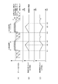
- FIG. 4 is a diagram showing a decrease in the output voltage of the fuel cell stack 1 due to general IV estimation.
- the controller 6 controls the opening degree of the anode pressure regulating valve 33 in order to push the generated water and nitrogen gas remaining in the downstream side of the anode gas flow path formed in the fuel cell stack 1 to the buffer tank 36.
- the pulsation operation for pulsating the pressure of the anode gas is performed.
- FIG. 4 (A) is a diagram showing fluctuations in the anode gas pressure supplied to the fuel cell stack 1.
- the pulsation pressure of the anode gas during IV estimation is indicated by a solid line
- the pulsation upper limit pressure and the pulsation lower limit pressure of the anode gas are respectively indicated by broken lines.
- FIG. 4B is a diagram showing an output current taken out from the fuel cell stack 1.
- FIG. 4C is a diagram showing the output voltage of the fuel cell stack 1.
- the horizontal axis of each drawing from FIG. 4A to FIG. 4C is a common time axis.
- the output current of the fuel cell stack 1 increases from the warm-up request current by the current control of the IV estimation unit 220.
- the increased output current is supplied from the fuel cell stack 1 to the battery 55 via the DC / DC converter 56.
- the warm-up request current is a current value taken out from the fuel cell stack 1 during the warm-up promotion operation.
- the pulsation lower limit pressure and the pulsation width from the pulsation lower limit pressure to the pulsation upper limit pressure are kept constant by the pressure control unit 210 as shown in FIG. Both pulsation upper limit pressures rise.
- the output voltage of the fuel cell stack 1 controls the voltage of the DC / DC converter 56 according to the IV characteristics of the fuel cell stack 1. To lower.
- the output current of the fuel cell stack 1 reaches the upper limit value set by the IV estimation unit 220. For this reason, as shown in FIG. 4B, the output current is lowered to the warm-up request current by the current control of the IV estimation unit 220.
- the upper limit value of the output current is set in advance according to the amount of current that can be supplied to the battery 55.
- the IV estimation unit 220 sequentially outputs the output current and output voltage of the fuel cell stack 1 detected at a predetermined sampling period from the current sensor 51 and the voltage sensor 52. get.
- the pulsation lower limit pressure and the pulsation upper limit pressure are both lowered by the pressure control unit 210 as shown in FIG.
- the pulsation lower limit pressure decreases while the anode gas pulsation pressure is decreased.
- the opening degree of the anode pressure regulating valve 33 is controlled so that the consumption amount of the anode gas consumed in the fuel cell stack 1 is larger than the supply flow rate of the anode gas.
- the pulsation pressure of the anode gas is greatly reduced below a predetermined pulsation width.
- the anode gas pressure in the fuel cell stack 1 temporarily becomes lower than the pressure in the buffer tank 36, so that the impurities accumulated in the buffer tank 36 are absorbed by the fuel cell stack. Backflow to 1. As a result, the impurity concentration in the fuel cell stack 1 increases, and the power generation efficiency of the fuel cell stack 1 temporarily decreases.
- the output voltage of the fuel cell stack 1 becomes lower than the original voltage value indicated by the broken line.
- the IV characteristics of the fuel cell stack 1 are estimated based on the output voltage detected by the voltage sensor 52 and the output current detected by the current sensor 51, the estimation accuracy of the IV characteristics of the fuel cell stack 1 is estimated. Becomes worse.
- the anode gas pressure is lowered in accordance with the control for lowering the target current during the IV estimation period, so that impurities flow backward from the buffer tank 36 to the fuel cell stack 1.
- the impurity concentration in the power generation region of each battery cell increases, the power generation efficiency of the fuel cell stack 1 decreases as a whole, and the output voltage of the fuel cell stack 1 decreases from the original voltage value. For this reason, the precision which estimates the IV characteristic of the fuel cell stack 1 will worsen.
- control unit 200 shown in FIG. 3 is provided with an anode gas restriction unit 230.
- the anode gas restriction unit 230 sets the target pressure of the anode gas based on the set value of the IV estimation flag to a predetermined lower limit value (hereinafter referred to as “backflow prevention”) for preventing the backflow of impurities from the buffer tank 36 to the fuel cell stack 1. It is a limiting unit set to “lower limit value”.
- the backflow prevention lower limit value is set in advance by, for example, experimental data. Or you may set based on the fall speed
- the IV estimation flag is a flag used for specifying a period during which IV estimation is performed, and is set by the IV estimation unit 220. For example, the IV estimation unit 220 sets the IV estimation flag to “1” at the start of the IV estimation period illustrated in FIG. 4 and sets the IV estimation flag to “0” at the end of the IV estimation period. Alternatively, the IV estimation unit 220 may set the IV estimation flag to “1” only during the current decrease period during which the output current of the fuel cell stack 1 is decreased.
- the anode gas restriction unit 230 sets the target pressure of the anode gas to the above-described backflow prevention lower limit value when the IV estimation flag indicates “1”.
- the anode gas restriction unit 230 increases the backflow prevention lower limit value as the upper limit value of the target current during the IV estimation period is larger.
- the anode gas restriction unit 230 obtains the target pressure of the anode gas from the pressure control unit 210, and does not limit the target pressure with the backflow prevention lower limit value. And output to the anode pressure regulating valve command unit 240.
- the anode pressure regulating valve command unit 240 sequentially acquires the detected pressure of the anode gas detected by the anode pressure sensor 34, and controls the anode pressure regulating valve 33 so that the pressure difference obtained by subtracting the detected pressure from the target pressure of the anode gas becomes zero. Feedback control.
- the anode pressure regulating valve command unit 240 increases the opening of the anode pressure regulating valve 33 so that the supply pressure of the anode gas increases when the pressure difference is larger than zero.
- the anode pressure regulating valve command unit 240 reduces the opening of the anode pressure regulating valve 33 so that the supply pressure of the anode gas is reduced.
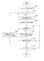
- FIG. 5 is a flowchart showing a limiting method for limiting a decrease in anode gas pressure accompanying IV estimation.
- control unit 200 of the controller 6 receives a start request from the key sensor 61, it starts the fuel cell system 100.
- control unit 200 acquires the stack inlet water temperature Ts from the second water temperature sensor 48 in step S901.
- step S902 the control unit 200 determines whether or not the stack inlet water temperature Ts is lower than the warm-up threshold (50 ° C.). If it is determined that the stack inlet water temperature Ts is 50 ° C. or higher, the process proceeds to step S909.
- the control unit 200 performs the warm-up promotion operation in step S903.
- the control unit 200 increases the power supplied to each of the cathode compressor 23 and the PTC heater 46 in the auxiliary machinery 57 to the upper limit value of the variable range.
- step S904 the IV estimation unit 220 of the control unit 200 executes current control in which the output current of the fuel cell stack 1 is amplified within a predetermined range at a predetermined cycle (for example, every 5 seconds). At this time, the IV estimation unit 220 changes the IV estimation flag from “0” to “1”.
- step S905 the anode gas restriction unit 230 of the control unit 200 determines whether current control is being executed by the IV estimation unit 220, that is, whether or not the IV estimation period is in progress. Specifically, the anode gas restriction unit 230 determines whether or not the IV estimation flag is set to “1”.
- step S906 when the anode gas restriction unit 230 determines that it is the IV estimation period, the anode gas restriction unit 230 sets the backflow prevention lower limit pressure described in FIG.
- the pressure control unit 210 sets the backflow prevention lower limit pressure to the target pressure of the anode gas, and adjusts the opening degree of the anode pressure regulating valve 33 so that the detected pressure of the anode gas supplied to the fuel cell stack 1 becomes the target pressure. .
- the IV estimation unit 220 obtains the current value and the voltage value from the current sensor 51 and the voltage sensor 52 during the current decrease period in which the output current is decreased. Obtain sequentially.
- the anode gas restriction unit 230 cancels the setting of the backflow prevention lower limit pressure to the pressure control unit 210.
- step S907 the IV estimation unit 220 obtains an approximate line of Formula (1) using the current value and the voltage value acquired during the current decrease period, refers to the approximate line, and as described in FIG. It is determined whether or not the stack 1 can provide the drive motor 53 with the minimum drive power. That is, the IV estimation unit 220 estimates the IV characteristics of the fuel cell stack 1 and determines whether or not the vehicle can travel using the estimated IV characteristics.
- step S905 If it is determined that the vehicle cannot travel, the process returns to step S905, and IV estimation is performed at a predetermined cycle until it is determined that the vehicle can travel. If it is determined in step S905 that it is not the IV estimation period, the process proceeds to step S909.
- step S909 the anode gas restriction unit 230 cancels the setting of the backflow prevention lower limit pressure for the pressure control unit 210.
- the pressure control unit 210 calculates the target pressure of the anode gas necessary for power generation of the fuel cell stack 1 based on the target current of the fuel cell stack 1, and the anode pressure is set so that the detected pressure of the anode gas becomes the target pressure.
- the opening degree of the pressure regulating valve 33 is adjusted.
- step S907 If it is determined in step S907 that the vehicle can travel, the control unit 200 determines in step S908 whether the stack inlet water temperature Ts has reached 50 ° C. Until the stack inlet water temperature Ts reaches 50 ° C., a series of processes from step S905 to S909 is repeated. When the stack inlet water temperature Ts reaches 50 ° C., the warm-up promotion operation ends, and the limiting method for limiting the pressure drop of the anode gas ends.
- the impurity concentration in the power generation region of the fuel cell stack 1 is lowered, and the power generation in the fuel cell stack 1 is performed. A decrease in efficiency can be suppressed.
- the anode gas restriction unit 230 restricts the pressure drop of the anode gas, so that the amount of impurities flowing back from the buffer tank 36 to the fuel cell stack 1 can be reduced. Can be suppressed. For this reason, it is possible to avoid a decrease in power generation efficiency of the fuel cell stack 1 due to the backflow of impurities, and it is possible to suppress a decrease in estimation accuracy of IV characteristics.
- FIG. 6 is a diagram showing a configuration of the anode gas control unit 201 in the second embodiment of the present invention.
- the fuel cell system of the present embodiment is basically the same as the configuration of the fuel cell system 100 shown in FIGS.
- the same components as those of the fuel cell system 100 are denoted by the same reference numerals, and detailed description thereof is omitted.
- the anode gas control unit 201 has a function of controlling the supply pressure of the anode gas supplied to the fuel cell stack 1 in the control unit 200 shown in FIG.
- the anode gas control unit 201 includes a pulsation operation unit 210A and a backflow prevention limiting unit 230A.
- the pulsation operation unit 210 ⁇ / b> A includes a pulsation width calculation unit 211, a pulsation upper limit pressure calculation unit 212, and a pulsation waveform calculation unit 213.
- the backflow prevention limiting unit 230A includes a pulsation restriction width holding unit 231, a pulsation width switching unit 232, a backflow prevention lower limit pressure holding unit 233, and a pulsation lower limit pressure switching unit 234.
- the pulsation operation unit 210A performs a pulsation operation that pulsates the pressure of the anode gas based on a pulsation width necessary for discharging impurities such as generated water and nitrogen gas accompanying power generation.
- the pulsation operation unit 210 ⁇ / b> A adjusts the pulsation width according to the wet state of the fuel cell stack 1.
- the wet state of the fuel cell stack 1 can be estimated by measuring the internal resistance (HFR) of the fuel cell stack 1, and the internal resistance of the fuel cell stack 1 is measured by an internal resistance measuring device (not shown).
- HFR internal resistance
- an internal resistance measuring device not shown.
- the internal resistance measuring device is connected to an intermediate terminal provided in the fuel cell stack 1 in addition to the anode electrode side output terminal 11 and the cathode electrode side output terminal 12.
- An intermediate potential between the potential of the anode electrode side output terminal 11 and the potential of the cathode electrode side output terminal 12 is output from the midway terminal.
- the internal resistance measuring device supplies a high-frequency (for example, 1 kHz) alternating current to each of the anode electrode side output terminal 11 and the cathode electrode side output terminal 12.
- the internal resistance measuring device detects an anode-side AC voltage generated between the anode electrode-side output terminal 11 and the halfway terminal, and also detects a cathode-side AC voltage generated between the cathode electrode-side output terminal 12 and the halfway terminal. Detect AC voltage.
- the internal resistance measuring device adjusts the amplitude of the alternating current at the anode electrode side output terminal 11 and the cathode electrode side output terminal 12 so that the anode side alternating voltage and the cathode side alternating voltage are equal to each other, An internal resistance value is calculated based on the alternating current.
- the backflow prevention limiting unit 230A limits the expansion of the decrease width of the anode gas pulsation pressure due to the amplitude of the output current of the fuel cell stack 1 during the IV estimation period.
- the backflow prevention lower limit pressure holding unit 233 holds the backflow prevention lower limit pressure that is set in order to limit the decrease width of the pulsation pressure of the anode gas.
- the backflow prevention lower limit pressure is output from the backflow prevention lower limit pressure holding unit 233 to the pulsation lower limit pressure switching unit 234.
- the pulsation lower limit pressure switching unit 234 switches the pulsation lower limit pressure of the anode gas from the cathode gas detection voltage detected by the cathode pressure sensor 24 to the backflow prevention lower limit pressure based on the set value of the IV estimation flag.
- the IV estimation flag is set by the IV estimation unit 220 as described in FIG.
- the pulsation lower limit pressure switching unit 234 determines that the fuel cell system 100 is in the IV estimation period, and acquires the backflow prevention lower limit pressure from the backflow prevention lower limit pressure holding unit 233. And output to the pulsation waveform calculation unit 213 as the pulsation lower limit pressure.
- the pulsation lower limit pressure switching unit 234 determines that the fuel cell system 100 is not in the IV estimation period, and uses the detected pressure output from the cathode pressure sensor 24 as the pulsation.
- the lower limit pressure is output to the pulsation waveform calculator 213.
- the pulsation width calculation unit 211 calculates a pulsation width W1 necessary for discharging generated water accompanying power generation based on the target current of the fuel cell stack 1.
- the pulsation width calculator 211 corrects the pulsation width W1 according to the internal resistance of the fuel cell stack 1.
- the pulsation width calculation unit 211 stores in advance a pulsation width calculation map in which the current of the fuel cell stack 1 and the pulsation width of the anode gas are associated with each other for each internal resistance value.
- the pulsation width calculation unit 211 acquires the target current and the internal resistance value
- the pulsation width calculation unit 211 refers to the pulsation width calculation map specified by the internal resistance value and determines the pulsation width associated with the target current as the target pulsation of the anode gas pressure.
- the width is output to the pulsation width switching unit 232.
- the pulsation width calculation unit 211 increases the pulsation width W1 because the amount of generated water accompanying power generation increases as the target current increases. Further, the lower the wetness of the electrolyte membrane, the greater the internal resistance of the fuel cell stack 1. Therefore, the pulsation width calculation unit 211 decreases the pulsation width W1 as the internal resistance of the fuel cell stack 1 increases.
- the pulsation restriction width holding unit 231 holds a restriction value for restricting the pulsation width W1 (hereinafter referred to as “pulsation restriction width W2”).
- the pulsation limit width W2 is a value smaller than the pulsation width W1, and nitrogen gas can be discharged from impurities remaining in the fuel cell stack 1 while preventing impurities from flowing back from the buffer tank 36 to the fuel cell stack 1.
- the pulsation restriction width W ⁇ b> 2 is output from the pulsation restriction width holding unit 231 to the pulsation width switching unit 232.
- the pulsation width switching unit 232 holds the target pulsation width of the anode gas pressure based on the set value of the IV estimation flag from the pulsation width W1 calculated by the pulsation width calculation unit 211 in the pulsation limit width holding unit 231. Switch to the pulsation limit width W2.
- the pulsation width switching unit 232 determines that the fuel cell system 100 is in the IV estimation period, and acquires the pulsation restriction width W2 from the pulsation restriction width holding unit 231. It outputs to the pulsation upper limit pressure calculation part 212 as a target pulsation width.
- the pulsation width switching unit 232 determines that the fuel cell system 100 is not in the IV estimation period, and uses the pulsation width W1 output from the pulsation width calculation unit 211. It outputs to the pulsation upper limit pressure calculation part 212.
- the pulsation upper limit pressure calculation unit 212 adds the target pulsation width to the detected pressure output from the cathode pressure sensor 24, and outputs the added value to the pulsation waveform calculation unit 213 as the pulsation upper limit pressure of the anode gas.
- the pulsation width W1 of the anode gas pressure is limited to the pulsation restriction width W2 by the backflow prevention restriction unit 230A during the IV estimation period in which the IV estimation unit 220 executes the current control.
- the pulsation waveform calculation unit 213 alternately selects the pulsation upper limit pressure and the pulsation lower limit pressure of the anode gas, and calculates the pulsation pressure of the anode gas so that the anode gas pressure has a pulsating waveform.
- the pulsation waveform calculation unit 213 calculates the pulsation pressure so that the anode gas pressure is increased at a constant rate from the pulsation lower limit pressure to the pulsation upper limit pressure.
- the pulsation waveform calculation unit 213 calculates the pulsation pressure so that the anode gas pressure is decreased at a constant rate from the pulsation upper limit pressure to the pulsation lower limit pressure.
- the pulsation waveform calculation unit 213 outputs the calculated pulsation pressure of the anode gas as a target pressure to the anode pressure regulating valve command unit 240 shown in FIG.
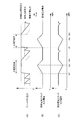
- FIG. 7 is a diagram showing a method of limiting the anode gas pressure by the anode gas control unit 201.
- FIG. 7 (A) is a diagram showing fluctuations in anode gas pulsation pressure during pulsation operation.
- the pulsation pressure of the anode gas is indicated by a solid line
- the pulsation upper limit pressure and the pulsation lower limit pressure are respectively indicated by broken lines.
- FIG. 7B is a diagram showing an output current taken out from the fuel cell stack 1.
- FIG. 7C is a diagram showing the output voltage of the fuel cell stack 1.
- the horizontal axis of each drawing from FIG. 7A to FIG. 7C is a common time axis.
- the warm-up promotion operation is performed as in FIG. 4, and current is supplied only from the fuel cell stack 1 to the auxiliary devices 57 by the voltage control of the DC / DC converter 56. Further, nitrogen gas and generated water staying in the fuel cell stack 1 are pushed out by the pulsation operation and accumulated in the buffer tank 36.
- the detected pressure of the cathode gas is set as the pulsation lower limit pressure, and a value obtained by adding the pulsation width W1 to the pulsation lower limit pressure is set as the pulsation upper limit pressure.
- the pulsation lower limit pressure switching unit 234 sets the anode gas pulsation lower limit pressure from the detection pressure of the cathode gas to limit the decrease in the anode gas pressure. It is switched to the backflow prevention lower limit pressure.
- the pulsation width switching unit 232 changes the target pulsation width of the anode gas pressure from the pulsation width W1 calculated by the pulsation width calculation unit 211 to a predetermined pulsation limit width W2 determined to prevent backflow of impurities. Can be switched. A value obtained by adding the pulsation restriction width W2 to the backflow prevention lower limit pressure is set as the pulsation upper limit pressure.
- the pulsation upper limit pressure set in the IV estimation period is set to an anode gas pressure value that can supply the minimum necessary anode gas flow rate to raise the output current of the fuel cell stack 1 to the upper limit value. Therefore, the larger the upper limit value of the output current during the IV estimation period, the larger the pulsation upper limit pressure is set.
- the pulsation limit width W2 is set to a predetermined pulsation width capable of discharging nitrogen gas staying in the anode gas flow path formed in the fuel cell stack 1.
- the backflow prevention lower limit pressure is fixed to a pressure value at which impurities do not backflow from the buffer tank 36 while ensuring the pulsation limit width W2.
- the target pressure of the cathode gas is increased by the pressure control unit 210 shown in FIG. 3, so that the detected pressure of the cathode gas output from the cathode pressure sensor 24 increases. .
- the pulsation lower limit pressure of the anode gas increases.
- the anode gas pressure is set to the pulsation limit width with the anode gas pulsation lower limit pressure and the pulsation upper limit pressure fixed. Pulsates at W2.
- the anode gas pressure is maintained in a state where the pulsation lower limit pressure and the pulsation upper limit pressure are fixed, as in the IV estimation period from time t61 to time t63. Pulsates with a pulsation limit width W2. Therefore, the IV characteristics of the fuel cell stack 1 can be estimated without causing impurities to flow back to the fuel cell stack 1.
- the output voltage temporarily decreases in the same manner as at time t47 shown in FIG.
- FIG. 8 is a diagram relating to a decrease in accuracy of IV characteristic estimation due to the backflow of impurities.
- FIG. 8A is a diagram showing the IV characteristics of the fuel cell stack 1 estimated by the IV estimation unit 220.
- the IV characteristic of the fuel cell stack 1 in the present embodiment is indicated by a solid line
- the IV characteristic when an impurity flows backward from the buffer tank 36 is indicated by a broken line
- the reference IV characteristic during normal operation is shown. Is indicated by a dotted line.
- the vertical axis indicates the output voltage V of the fuel cell stack 1
- the horizontal axis indicates the output current I of the fuel cell stack 1.
- FIG. 8B is a diagram showing the characteristics of the fuel cell stack 1 when the IV characteristics shown in FIG. 8A are approximated using the formula (1) described in FIG.
- the characteristics of the fuel cell stack 1 in the present embodiment are indicated by solid lines, and the characteristics of the fuel cell stack 1 when impurities flow back from the buffer tank 36 are indicated by broken lines.
- the vertical axis indicates the voltage difference ⁇ V obtained by subtracting the detected value of the output voltage from the voltage value of the reference IV characteristic, and the horizontal axis indicates the output current I of the fuel cell stack 1.
- the upper limit current Ic is the maximum value when the output current is increased during the IV estimation period, and is the upper limit value of the output current detectable range.
- the current range above the upper limit current Ic is the IV estimation range estimated by the equation (1).
- the slope of the approximate line when the impurities flow back into the fuel cell stack 1 is larger than the slope of the approximate line of the present embodiment. That is, the coefficient a of the formula (1) obtained when the impurities flow back is smaller than the coefficient a obtained in the present embodiment.
- the IV characteristic when the impurity flows back is estimated as a better characteristic than the actual IV characteristic of the fuel cell stack 1 in the IV estimation range. For this reason, it is necessary to increase the threshold value for permitting traveling in consideration of such circumstances, and it becomes difficult to accurately permit traveling.
- the IV estimation unit 220 of the present embodiment can accurately estimate the IV characteristics of the fuel cell stack 1 as compared with the case where impurities flow backward.
- the backflow prevention limiting unit 230A changes the anode gas pulsation lower limit pressure while the IV estimation unit 220 changes the output current of the fuel cell stack 1, that is, during the IV estimation period. Fix to the predetermined pressure (backflow prevention lower limit pressure).
- the backflow prevention limiting unit 230A can prevent the decrease in the anode gas pressure from decreasing during the IV estimation period, so that the backflow of nitrogen gas from the buffer tank 36 to the fuel cell stack 1 can be suppressed. Therefore, it is possible to suppress a decrease in the estimation accuracy of the IV characteristics due to the backflow of impurities while suppressing an increase in the impurity concentration staying in the power generation region of the fuel cell stack 1 by the buffer tank 36.
- the pulsation operation unit 210A pulsates the pressure of the anode gas based on the pulsation width W1 necessary for discharging the generated water accompanying the power generation of the fuel cell stack 1. And during the IV estimation period, the backflow prevention limiting unit 230A limits the pulsation width W1 by the pulsation operation unit 210A to a pulsation restriction width W2 that is smaller than the pulsation width necessary for discharging the generated water.
- the pulsation limit width W2 is set to the minimum pulsation width necessary for the discharge of nitrogen gas.
- the IV estimation unit 220 acquires the output current and output voltage of the fuel cell stack 1 from the current sensor 51 and the voltage sensor 52 during the current reduction period in which the output current of the fuel cell stack 1 is reduced.
- the IV characteristic is recovered by warm-up, so that the reference voltage and output of the reference IV characteristic increase as the output current increases.
- the voltage difference ⁇ V from the voltage tends to be small.
- the slope a of the equation (1) described with reference to FIG. 2 becomes small, and it is determined that the estimated IV characteristic is better than the actual IV characteristic.
- the backflow prevention lower limit pressure is set from when the output current of the fuel cell stack 1 is raised to when it is lowered.
- a lower limit pressure may be set. Even in this case, it is possible to suppress a decrease in the accuracy of IV characteristic estimation due to the backflow of impurities accumulated in the buffer tank 36. Furthermore, the drainage of the fuel cell stack 1 can be improved by shortening the time for limiting the pulsation width W1 and increasing the time for pulsation with the pulsation width W1.
- FIG. 9 is a diagram showing a configuration of the anode gas control unit 202 in the third embodiment of the present invention.
- the fuel cell system of the present embodiment is basically the same as the configuration of the fuel cell system 100 shown in FIGS.
- the same components as those of the fuel cell system 100 are denoted by the same reference numerals, and detailed description thereof is omitted.
- the anode gas control unit 202 has a function of controlling the supply pressure of the anode gas supplied to the fuel cell stack 1 in the control unit 200 shown in FIG.
- the anode gas control unit 202 includes a pulsation operation unit 210B and a backflow prevention limiting unit 230B.
- the pulsation operation unit 210B has basically the same configuration as the pulsation operation unit 210A shown in FIG. 6, and the same components as those in the pulsation operation unit 210A are denoted by the same reference numerals and description thereof is omitted here.
- the backflow prevention limiting unit 230B includes a backflow prevention fixed pressure holding unit 235 and a target pressure switching unit 236.
- the backflow prevention fixed pressure holding unit 235 holds a fixed value (hereinafter referred to as “backflow prevention fixed pressure”) determined to fix the anode gas pulsation pressure during the IV estimation period.
- the backflow prevention fixed pressure is a pressure value set to limit the anode gas pressure drop accompanying the current control of the IV estimation unit 220.
- the backflow prevention fixed pressure is output from the backflow prevention fixed pressure holding unit 235 to the target pressure switching unit 236.
- the target pressure switching unit 236 calculates the target pressure of the anode gas from the pulsation pressure calculated by the pulsation waveform calculation unit 213.
- the backflow prevention fixed pressure holding unit 235 is switched to a fixed value.
- the target pressure switching unit 236 determines that the IV estimation period is in progress, acquires the backflow prevention fixed pressure from the backflow prevention fixed pressure holding unit 235, and sets it as the target pressure. It outputs to the anode pressure regulating valve command unit 240 shown in FIG.
- the target pressure switching unit 236 determines that the IV estimation period is not in progress, and determines the pulsation pressure output from the pulsation waveform calculation unit 213 as the anode pressure regulating valve command unit 240. Output to.
- the pulsation pressure of the anode gas is limited to the backflow prevention fixed pressure by the backflow prevention restriction unit 230B.
- FIG. 10 is a diagram showing a method of limiting the anode gas pressure by the anode gas control unit 202. Note that the vertical axis of each drawing from FIG. 10A to FIG. 10C is the same as the vertical axis of each drawing from FIG. 7A to FIG. The horizontal axis of each drawing from A) to FIG. 10C is a common time axis.
- the IV estimation unit 220 sets the IV estimation flag to “1”, and outside the IV estimation period, the IV estimation flag is set to “0”.
- the IV estimation flag indicates “0”
- the detected value of the cathode gas pressure is set as the pulsation lower limit pressure
- the pulsation width W1 calculated by the pulsation width calculation unit 211 is added to the pulsation lower limit pressure. This value is set as the pulsation upper limit pressure.
- the target pressure switching unit 236 causes the target pressure of the anode gas to prevent the backflow of the cathode gas from being limited to a predetermined backflow that is determined to limit the pressure drop of the anode gas. Switch to fixed pressure.
- the backflow prevention fixed pressure is set to an anode gas pressure value that can supply a minimum necessary anode gas flow rate when the output current is increased to the upper limit value during the IV estimation period. Therefore, as the upper limit value of the output current is increased during the IV estimation period, the backflow prevention fixed pressure is set to a larger value.
- the anode gas pressure is set to the fixed backflow prevention fixed pressure, so that the anode gas is supplied to the fuel cell stack 1 at a flow rate necessary for power generation, and from the buffer tank 36 to the fuel cell stack 1. Nitrogen gas can be prevented from flowing backward.
- the IV characteristic of the fuel cell stack 1 can be accurately estimated. Also, in the IV estimation period from time t04 to time t06, the IV characteristics of the fuel cell stack 1 are estimated without causing impurities to flow back into the fuel cell stack 1 as in the IV estimation period from time t01 to time t03. can do.
- the backflow prevention limiting unit 230B switches the anode gas pressure from the pulsation pressure by the pulsation operation unit 210B to a predetermined pressure (backflow prevention fixed pressure) during the IV estimation period.
- the pressure drop of the anode gas can be limited during the IV estimation period, so that impurities can be prevented from flowing back from the buffer tank 36 to the fuel cell stack 1. Therefore, it is possible to suppress a decrease in the accuracy of IV characteristic estimation.
- the present invention can also be applied to a configuration that calculates the pulsation lower limit pressure based on the pulsation upper limit pressure. It is.
- the present invention can also be applied to a fuel cell system in which a humidifier such as a water recovery device (WRD) is provided in the cathode gas supply passage 21.
- a humidifier such as a water recovery device (WRD)
- the cathode pressure sensor 24 is provided in the cathode gas supply passage 21 upstream from the humidifier, and the detected pressure detected by the cathode pressure sensor 24 is set as the pulsation lower limit pressure of the anode gas.
- the present invention has been described with respect to the example in which IV estimation is performed during the warm-up promotion operation, the IV estimation may be performed during normal operation, and in this case, the same effect as in the present embodiment can be obtained.
Landscapes
- Life Sciences & Earth Sciences (AREA)
- Engineering & Computer Science (AREA)
- Manufacturing & Machinery (AREA)
- Sustainable Development (AREA)
- Sustainable Energy (AREA)
- Chemical & Material Sciences (AREA)
- Chemical Kinetics & Catalysis (AREA)
- Electrochemistry (AREA)
- General Chemical & Material Sciences (AREA)
- Fuel Cell (AREA)
Abstract
Priority Applications (5)
| Application Number | Priority Date | Filing Date | Title |
|---|---|---|---|
| US15/027,402 US9843056B2 (en) | 2013-10-08 | 2014-09-10 | Fuel cell system and method for controlling fuel cell system |
| CN201480053695.8A CN105594046B (zh) | 2013-10-08 | 2014-09-10 | 燃料电池系统以及燃料电池系统的控制方法 |
| EP14851766.7A EP3057164B1 (fr) | 2013-10-08 | 2014-09-10 | Système de pile à combustible et procédé permettant de réguler un système de pile à combustible |
| JP2015541492A JP6160703B2 (ja) | 2013-10-08 | 2014-09-10 | 燃料電池システム及び燃料電池システムの制御方法 |
| CA2926746A CA2926746C (fr) | 2013-10-08 | 2014-09-10 | Systeme de pile a combustible et procede permettant de reguler un systeme de pile a combustible |
Applications Claiming Priority (2)
| Application Number | Priority Date | Filing Date | Title |
|---|---|---|---|
| JP2013-211335 | 2013-10-08 | ||
| JP2013211335 | 2013-10-08 |
Publications (1)
| Publication Number | Publication Date |
|---|---|
| WO2015053034A1 true WO2015053034A1 (fr) | 2015-04-16 |
Family
ID=52812854
Family Applications (1)
| Application Number | Title | Priority Date | Filing Date |
|---|---|---|---|
| PCT/JP2014/073961 WO2015053034A1 (fr) | 2013-10-08 | 2014-09-10 | Système de pile à combustible et procédé permettant de réguler un système de pile à combustible |
Country Status (6)
| Country | Link |
|---|---|
| US (1) | US9843056B2 (fr) |
| EP (1) | EP3057164B1 (fr) |
| JP (1) | JP6160703B2 (fr) |
| CN (1) | CN105594046B (fr) |
| CA (1) | CA2926746C (fr) |
| WO (1) | WO2015053034A1 (fr) |
Cited By (1)
| Publication number | Priority date | Publication date | Assignee | Title |
|---|---|---|---|---|
| EP3121890A1 (fr) * | 2015-07-23 | 2017-01-25 | Toyota Jidosha Kabushiki Kaisha | Système de pile à combustible |
Families Citing this family (5)
| Publication number | Priority date | Publication date | Assignee | Title |
|---|---|---|---|---|
| KR101611123B1 (ko) * | 2015-02-16 | 2016-04-08 | 현대자동차주식회사 | 연료전지 출력 추정방법 |
| JP7127306B2 (ja) * | 2018-03-16 | 2022-08-30 | トヨタ自動車株式会社 | 車両及びその制御方法 |
| DE202019102314U1 (de) * | 2019-04-25 | 2020-07-29 | Aradex Ag | Vorrichtung mit wenigstens einer Brennstoffzelle |
| CN112820901B (zh) * | 2020-12-31 | 2022-04-12 | 华中科技大学 | 一种解决封闭环境中氢氧燃料电池水淹问题的方法 |
| CN114914488B (zh) * | 2022-05-25 | 2023-04-14 | 厦门金龙联合汽车工业有限公司 | 一种燃料电池缺氢检测与诊断方法 |
Citations (6)
| Publication number | Priority date | Publication date | Assignee | Title |
|---|---|---|---|---|
| JP2000357526A (ja) | 1999-06-15 | 2000-12-26 | Nippon Telegr & Teleph Corp <Ntt> | 燃料電池発電装置およびそのセルスタックの劣化診断方法 |
| JP2004241272A (ja) * | 2003-02-06 | 2004-08-26 | Toyota Motor Corp | 燃料電池制御装置、その方法及びその装置を搭載した車両 |
| JP2009026525A (ja) * | 2007-07-18 | 2009-02-05 | Toyota Motor Corp | 燃料電池 |
| WO2010058747A1 (fr) * | 2008-11-21 | 2010-05-27 | 日産自動車株式会社 | Système de pile à combustible et procédé de commande associé |
| WO2013027634A1 (fr) * | 2011-08-23 | 2013-02-28 | 日産自動車株式会社 | Dispositif d'estimation de caractéristiques de production d'énergie d'une pile à combustible |
| WO2014054560A1 (fr) * | 2012-10-01 | 2014-04-10 | 日産自動車株式会社 | Système de pile à combustible et procédé de commande |
Family Cites Families (3)
| Publication number | Priority date | Publication date | Assignee | Title |
|---|---|---|---|---|
| JP3972675B2 (ja) * | 2002-02-15 | 2007-09-05 | 日産自動車株式会社 | 燃料電池システム |
| JP4784076B2 (ja) * | 2004-11-26 | 2011-09-28 | 日産自動車株式会社 | 燃料電池システムの制御装置 |
| JP5267669B2 (ja) * | 2009-07-07 | 2013-08-21 | 日産自動車株式会社 | 燃料電池パワープラントの運転制御装置及び運転制御方法 |
-
2014
- 2014-09-10 CN CN201480053695.8A patent/CN105594046B/zh not_active Expired - Fee Related
- 2014-09-10 JP JP2015541492A patent/JP6160703B2/ja not_active Expired - Fee Related
- 2014-09-10 US US15/027,402 patent/US9843056B2/en active Active
- 2014-09-10 CA CA2926746A patent/CA2926746C/fr active Active
- 2014-09-10 EP EP14851766.7A patent/EP3057164B1/fr not_active Not-in-force
- 2014-09-10 WO PCT/JP2014/073961 patent/WO2015053034A1/fr active Application Filing
Patent Citations (6)
| Publication number | Priority date | Publication date | Assignee | Title |
|---|---|---|---|---|
| JP2000357526A (ja) | 1999-06-15 | 2000-12-26 | Nippon Telegr & Teleph Corp <Ntt> | 燃料電池発電装置およびそのセルスタックの劣化診断方法 |
| JP2004241272A (ja) * | 2003-02-06 | 2004-08-26 | Toyota Motor Corp | 燃料電池制御装置、その方法及びその装置を搭載した車両 |
| JP2009026525A (ja) * | 2007-07-18 | 2009-02-05 | Toyota Motor Corp | 燃料電池 |
| WO2010058747A1 (fr) * | 2008-11-21 | 2010-05-27 | 日産自動車株式会社 | Système de pile à combustible et procédé de commande associé |
| WO2013027634A1 (fr) * | 2011-08-23 | 2013-02-28 | 日産自動車株式会社 | Dispositif d'estimation de caractéristiques de production d'énergie d'une pile à combustible |
| WO2014054560A1 (fr) * | 2012-10-01 | 2014-04-10 | 日産自動車株式会社 | Système de pile à combustible et procédé de commande |
Cited By (3)
| Publication number | Priority date | Publication date | Assignee | Title |
|---|---|---|---|---|
| EP3121890A1 (fr) * | 2015-07-23 | 2017-01-25 | Toyota Jidosha Kabushiki Kaisha | Système de pile à combustible |
| CN106374123A (zh) * | 2015-07-23 | 2017-02-01 | 丰田自动车株式会社 | 燃料电池系统 |
| CN106374123B (zh) * | 2015-07-23 | 2019-05-10 | 丰田自动车株式会社 | 燃料电池系统 |
Also Published As
| Publication number | Publication date |
|---|---|
| CN105594046A (zh) | 2016-05-18 |
| US9843056B2 (en) | 2017-12-12 |
| EP3057164A4 (fr) | 2016-10-12 |
| US20160254554A1 (en) | 2016-09-01 |
| CN105594046B (zh) | 2018-06-22 |
| EP3057164A1 (fr) | 2016-08-17 |
| CA2926746C (fr) | 2019-07-09 |
| JPWO2015053034A1 (ja) | 2017-03-09 |
| JP6160703B2 (ja) | 2017-07-12 |
| CA2926746A1 (fr) | 2015-04-16 |
| EP3057164B1 (fr) | 2017-11-08 |
Similar Documents
| Publication | Publication Date | Title |
|---|---|---|
| JP6160703B2 (ja) | 燃料電池システム及び燃料電池システムの制御方法 | |
| US10020553B2 (en) | Fuel cell system and method for controlling fuel cell system | |
| US10854900B2 (en) | Fuel cell system and control method for fuel cell system | |
| JP6171846B2 (ja) | 燃料電池の電力調整システム | |
| JP5928603B2 (ja) | 燃料電池システム及び制御方法 | |
| KR20190053102A (ko) | 연료 전지 시스템 및 그 제어 방법 | |
| US9812722B2 (en) | Fuel cell system and control method for fuel cell system | |
| US9780397B2 (en) | Fuel cell system | |
| JP6160313B2 (ja) | 燃料電池システム | |
| JP6090052B2 (ja) | 燃料電池システム | |
| JP6156041B2 (ja) | 燃料電池システム | |
| JP2015076246A (ja) | 燃料電池システム | |
| JP2016122548A (ja) | 燃料電池システム |
Legal Events
| Date | Code | Title | Description |
|---|---|---|---|
| 121 | Ep: the epo has been informed by wipo that ep was designated in this application |
Ref document number: 14851766 Country of ref document: EP Kind code of ref document: A1 |
|
| ENP | Entry into the national phase |
Ref document number: 2015541492 Country of ref document: JP Kind code of ref document: A |
|
| WWE | Wipo information: entry into national phase |
Ref document number: 15027402 Country of ref document: US |
|
| ENP | Entry into the national phase |
Ref document number: 2926746 Country of ref document: CA |
|
| NENP | Non-entry into the national phase |
Ref country code: DE |
|
| REEP | Request for entry into the european phase |
Ref document number: 2014851766 Country of ref document: EP |
|
| WWE | Wipo information: entry into national phase |
Ref document number: 2014851766 Country of ref document: EP |