WO2015049920A1 - イオン発生装置 - Google Patents
イオン発生装置 Download PDFInfo
- Publication number
- WO2015049920A1 WO2015049920A1 PCT/JP2014/070671 JP2014070671W WO2015049920A1 WO 2015049920 A1 WO2015049920 A1 WO 2015049920A1 JP 2014070671 W JP2014070671 W JP 2014070671W WO 2015049920 A1 WO2015049920 A1 WO 2015049920A1
- Authority
- WO
- WIPO (PCT)
- Prior art keywords
- ion
- ion generator
- air
- electrode
- ions
- Prior art date
- Legal status (The legal status is an assumption and is not a legal conclusion. Google has not performed a legal analysis and makes no representation as to the accuracy of the status listed.)
- Ceased
Links
Images






Classifications
-
- H—ELECTRICITY
- H01—ELECTRIC ELEMENTS
- H01T—SPARK GAPS; OVERVOLTAGE ARRESTERS USING SPARK GAPS; SPARKING PLUGS; CORONA DEVICES; GENERATING IONS TO BE INTRODUCED INTO NON-ENCLOSED GASES
- H01T23/00—Apparatus for generating ions to be introduced into non-enclosed gases, e.g. into the atmosphere
-
- F—MECHANICAL ENGINEERING; LIGHTING; HEATING; WEAPONS; BLASTING
- F24—HEATING; RANGES; VENTILATING
- F24F—AIR-CONDITIONING; AIR-HUMIDIFICATION; VENTILATION; USE OF AIR CURRENTS FOR SCREENING
- F24F11/00—Control or safety arrangements
- F24F11/88—Electrical aspects, e.g. circuits
-
- F—MECHANICAL ENGINEERING; LIGHTING; HEATING; WEAPONS; BLASTING
- F24—HEATING; RANGES; VENTILATING
- F24F—AIR-CONDITIONING; AIR-HUMIDIFICATION; VENTILATION; USE OF AIR CURRENTS FOR SCREENING
- F24F11/00—Control or safety arrangements
- F24F11/30—Control or safety arrangements for purposes related to the operation of the system, e.g. for safety or monitoring
-
- F—MECHANICAL ENGINEERING; LIGHTING; HEATING; WEAPONS; BLASTING
- F24—HEATING; RANGES; VENTILATING
- F24F—AIR-CONDITIONING; AIR-HUMIDIFICATION; VENTILATION; USE OF AIR CURRENTS FOR SCREENING
- F24F8/00—Treatment, e.g. purification, of air supplied to human living or working spaces otherwise than by heating, cooling, humidifying or drying
- F24F8/10—Treatment, e.g. purification, of air supplied to human living or working spaces otherwise than by heating, cooling, humidifying or drying by separation, e.g. by filtering
- F24F8/192—Treatment, e.g. purification, of air supplied to human living or working spaces otherwise than by heating, cooling, humidifying or drying by separation, e.g. by filtering by electrical means, e.g. by applying electrostatic fields or high voltages
- F24F8/194—Treatment, e.g. purification, of air supplied to human living or working spaces otherwise than by heating, cooling, humidifying or drying by separation, e.g. by filtering by electrical means, e.g. by applying electrostatic fields or high voltages by filtering using high voltage
-
- F—MECHANICAL ENGINEERING; LIGHTING; HEATING; WEAPONS; BLASTING
- F24—HEATING; RANGES; VENTILATING
- F24F—AIR-CONDITIONING; AIR-HUMIDIFICATION; VENTILATION; USE OF AIR CURRENTS FOR SCREENING
- F24F8/00—Treatment, e.g. purification, of air supplied to human living or working spaces otherwise than by heating, cooling, humidifying or drying
- F24F8/30—Treatment, e.g. purification, of air supplied to human living or working spaces otherwise than by heating, cooling, humidifying or drying by ionisation
-
- F—MECHANICAL ENGINEERING; LIGHTING; HEATING; WEAPONS; BLASTING
- F24—HEATING; RANGES; VENTILATING
- F24F—AIR-CONDITIONING; AIR-HUMIDIFICATION; VENTILATION; USE OF AIR CURRENTS FOR SCREENING
- F24F8/00—Treatment, e.g. purification, of air supplied to human living or working spaces otherwise than by heating, cooling, humidifying or drying
- F24F8/80—Self-contained air purifiers
-
- F—MECHANICAL ENGINEERING; LIGHTING; HEATING; WEAPONS; BLASTING
- F24—HEATING; RANGES; VENTILATING
- F24F—AIR-CONDITIONING; AIR-HUMIDIFICATION; VENTILATION; USE OF AIR CURRENTS FOR SCREENING
- F24F2110/00—Control inputs relating to air properties
-
- Y—GENERAL TAGGING OF NEW TECHNOLOGICAL DEVELOPMENTS; GENERAL TAGGING OF CROSS-SECTIONAL TECHNOLOGIES SPANNING OVER SEVERAL SECTIONS OF THE IPC; TECHNICAL SUBJECTS COVERED BY FORMER USPC CROSS-REFERENCE ART COLLECTIONS [XRACs] AND DIGESTS
- Y02—TECHNOLOGIES OR APPLICATIONS FOR MITIGATION OR ADAPTATION AGAINST CLIMATE CHANGE
- Y02A—TECHNOLOGIES FOR ADAPTATION TO CLIMATE CHANGE
- Y02A50/00—TECHNOLOGIES FOR ADAPTATION TO CLIMATE CHANGE in human health protection, e.g. against extreme weather
- Y02A50/20—Air quality improvement or preservation, e.g. vehicle emission control or emission reduction by using catalytic converters
Definitions
- the present invention relates to an ion generator.
- ion generators include an ion generator that emits ions into the air and an ion sensor that measures the amount of ions in the air. According to this ion generator, it is possible to monitor the deterioration of the ion generator over time based on the measurement result of the ion amount by the ion sensor, or to control the ion release amount by the ion generator.
- Japanese Patent Application Laid-Open No. 2004-228561 discloses a conventional technique related to such an ion generator.
- the conventional air conditioner described in Patent Document 1 individually includes an ion generator that emits ions into the air and an ion sensor that measures the amount of ions in the air. This air conditioner detects the amount of ions in the room by an ion sensor and adjusts the amount of ions in the room to be a predetermined amount.
- some ion sensors have a mechanism for detecting, as a current, a charge per unit time generated when ions touch a collection electrode formed on the surface of a circuit board.
- the electric current generated when the ion touches the collecting electrode is an extremely small current of picoampere (pA) to nanoampere (nA) level, and an insulation resistance of gigaohm (G ⁇ ) or more is required between circuit patterns. .
- the present invention has been made in view of the above points, can suppress the occurrence of problems such as dust adhesion and salt damage on the circuit board of the ion sensor, and can maintain an insulating state between circuit patterns.
- An object is to provide a possible ion generator.
- an ion generator of the present invention includes an ion generator having an ion generator that emits ions into the air, a circuit board, and the circuit that collects ions emitted by the ion generator.
- An ion sensor having a collection electrode provided on the first surface of the substrate and a circuit portion provided on the second surface of the circuit board that operates to measure the amount of ions in the air using the collection electrode;
- the ion generator and the ion sensor are built in, and have an emission opening that exposes the ion generation part to the outside and a collection opening that exposes the collection electrode to the outside, and is disposed facing the air circulation space.
- a main body housing wherein the second surface is liquid-tightly sealed while forming an air layer on the surface of the second surface of the circuit board.
- the second surface provided with the circuit portion of the circuit board is liquid-tightly sealed, intrusion of dust, salt water, water, or the like into the circuit portion is prevented. Therefore, the occurrence of problems such as dust adhesion and salt damage on the circuit board is suppressed. Furthermore, since the air layer is formed on the surface of the second surface of the circuit board, the circuit portion is in an air insulating state. Therefore, the insulation state between circuit patterns is maintained.
- liquid tightness mentioned here is the same as “water tightness” that prevents the flow of water and “airtightness” that prevents the flow of gas. Means that. Sealing the second surface of the circuit board in a liquid-tight manner prevents the flow of solids and liquids such as dust, but the gas may be air-tight or breathable.
- a case incorporating the ion sensor an electrode opening exposing the collection electrode to the outside of the case provided in the case, and the case corresponding to the periphery of the electrode opening And a sealing member that liquid-tightly seals the inside of the case provided between the circuit board and the first surface of the circuit board.
- the ion sensor is built in the case, only the collecting electrode is exposed to the outside from the electrode opening, and the periphery of the electrode opening is liquid-tightly sealed with the sealing member. Therefore, intrusion of dust, salt water, water or the like into the case is prevented while exposing the collecting electrode to the outside of the case. Moreover, since an air layer is formed on the surface of the second surface of the circuit board inside the case, the circuit portion is in an air-insulated state.
- the collection electrode and the sealing member overlap with the first surface of the circuit board.
- the frame which has a ceiling part spaced apart and opposed from the said 2nd surface attached to the said 2nd surface of the said circuit board might cover the circumference
- the second surface is liquid-tightly sealed with the sealing resin while forming an air layer on the surface of the second surface of the circuit board using the frame. Therefore, the effect
- a positive ion generator that discharges positive ions into the air a negative ion generator that discharges negative ions into the air
- the body housing corresponding to the periphery of the collection opening.
- a second rib for the generation of ions disposed at a distance from the positive ion generating portion or the negative ion generating portion disposed at a distance from the collection opening. Part emits It is characterized by and a shielding rib for preventing flowing into the collection aperture of the ion.
- the first rib guides the ions flowing along the air flow direction to the collecting electrode. For example, ions staying in the stagnation portion of the air in the direction in which the second rib intersects the first rib are guided to the collecting electrode.
- the shielding rib prevents inflow of ions emitted from the ion generating section that is not desired to be guided to the collecting electrode into the collecting electrode. Therefore, polar ions to be measured by the ion sensor among positive ions or negative ions are efficiently guided to the collecting electrode.
- the ion generator having the above-described configuration is an ion generator arranged to face the air circulation space formed at least in part using polystyrene foam, and emits positive ions into the air.
- the ion sensor is arranged on the downstream side in the air flow direction of the positive ion generator.
- the ion sensor suitably collects positive ions and efficiently measures the amount of ions.
- the ion generating apparatus having the above-described configuration includes a light emitting unit that irradiates light to the outside of the main body housing, and the light emitting unit is disposed on the downstream side in the air flow direction of the ion generating unit. It is said.
- This configuration prevents charging of the light emitting part. Accordingly, accumulation of dust in the light emitting unit is suppressed, and light is effectively irradiated to the outside of the main body housing.
- the circuit unit of the ion sensor includes an electrode setting unit that sets a voltage of the collection electrode to a reference voltage when the collection electrode is reset, and a voltage of the collection electrode.
- the voltage of the collection electrode measured by the electrode voltage measurement unit measured immediately after resetting the collection electrode and when the ion generator is not performing an ion emission operation is the reference voltage.
- a reference voltage determination unit that determines whether or not the voltage of the collection electrode is immediately after the reference voltage determination unit is reset and when the ion generator is not performing an ion emission operation.
- an output unit that outputs information relating to the determination that the voltage is not the reference voltage.
- the ion sensor sets the voltage of the collection electrode to the reference voltage when the collection electrode is reset, the ion sensor captures immediately after the collection electrode is reset and when the ion generator is not performing the ion emission operation.
- the abnormality of the ion sensor is identified. Therefore, the abnormality of the ion generator or the deterioration with time is distinguished from the abnormality of the ion sensor.
- an ion generator that can suppress the occurrence of problems such as dust adhesion and salt damage on the circuit board of an ion sensor and can maintain an insulation state between circuit patterns. can do.
- 1 is a perspective view of an ion generator according to a first embodiment of the present invention. It is a front view of the ion generator concerning a 1st embodiment of the present invention. It is a top view of the ion generator concerning a 1st embodiment of the present invention. It is a side view of the ion generator concerning a 1st embodiment of the present invention. It is a rear view of the ion generator which concerns on 1st Embodiment of this invention. It is a rear view of the state which removed the lid
- FIG. 9 is a vertical sectional side view of the ion sensor and case shown in FIG. 8 taken along line XX. It is a perspective view in the state where the lid of the case of the ion sensor of the ion generator concerning a 1st embodiment of the present invention was removed. It is a rear view of the state which removed the cover of the case of the ion sensor of the ion generator concerning a 1st embodiment of the present invention.
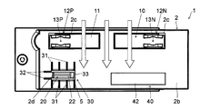
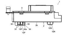
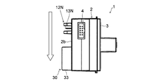
- FIGS. 1 to 5 are a perspective view, a front view, a top view, a side view, and a rear view of an ion generator.
- FIG. 6 is a rear view of the ion generator with the lid removed.
- the ion generator 1 includes a main body housing 2, a lid portion 3, a terminal portion 4, an ion generator 10, an ion sensor 20, a rib portion 30, and a light emitting portion 40.
- the main body housing 2 is a box-shaped member whose outer shape is a substantially rectangular parallelepiped shape, and one surface thereof opens as a main opening 2a (see FIG. 6).
- a lid 3 is attached to the main opening 2a of the main body housing 2 and closed.
- the front surface 2b which is the other surface facing the main opening 2a of the main body housing 2, is provided with an ion discharge opening 2c and a collection opening 2d each having a substantially rectangular shape.
- the ion generator 1 is arranged so that the front surface 2b having the discharge opening 2c and the collection opening 2d of the main body housing 2 faces the air circulation space.
- the white arrows drawn in FIGS. 1, 2 and 4 indicate the air flow path and flow direction.
- the lid 3 has a substantially rectangular shape in plan view covering the main opening 2a of the main body housing 2.
- the lid 3 is fitted into the main opening 2a and tightened with a screw 3a to seal the main opening 2a (see FIGS. 3 to 5).
- the terminal unit 4 is disposed on the side surface of the main body housing 2 as shown in FIGS. 1 and 4 and is electrically connected to the ion generator 10, the ion sensor 20, and the light emitting unit 40.
- the terminal unit 4 receives power supply from the outside and supplies the power to the ion generator 10, the ion sensor 20, and the light emitting unit 40. Further, the terminal unit 4 is electrically connected to an external control circuit, for example, and used to exchange control signals and the like.
- the ion generator 10 is disposed adjacent to the two discharge openings 2c of the main body housing 2 as shown in FIGS.
- the ion generator 10 can be attached to and detached from the main body housing 2.
- discharge electrodes 13 13P, 13N
- discharge for discharging ions and other electronic parts are provided in the housing 11, and are packaged as shown in FIG. 6, for example.
- the ion generator 10 includes a discharge circuit unit (not shown), a positive ion generation unit 12P, and a negative ion generation unit 12N.
- the discharge circuit unit includes a high-voltage electricity generation circuit that generates a high-voltage electric pulse upon receiving external power supply.
- the positive ion generator 12P and the negative ion generator 12N are arranged side by side at a predetermined interval (see FIGS. 1 and 2), and project toward the outside of the main body housing 2 of the ion generator 10 through separate discharge openings 2c. Facing the air circulation space (see FIGS. 3 and 4).
- the positive ion generator 12P and the negative ion generator 12N are arranged in a direction that intersects the air flow direction of the air flow space and forms a substantially right angle.
- the positive ion generation unit 12P and the negative ion generation unit 12N may be collectively referred to as the ion generation unit 12.
- the positive ion generator 12P includes a positive discharge electrode 13P
- the negative ion generator 12N includes a negative discharge electrode 13N.
- the positive discharge electrode 13P and the negative discharge electrode 13N are each formed in a needle shape protruding outward from the housing 11. Both the positive ion generator 12P and the negative ion generator 12N have the same structure, and a high voltage generated by the high voltage electricity generator circuit is supplied to each of the positive discharge electrode 13P and the negative discharge electrode 13N to generate a discharge. Release.
- a voltage having an AC waveform or an impulse waveform is applied to the positive discharge electrode 13P and the negative discharge electrode 13N of the ion generator 10.
- a positive voltage is applied to the positive discharge electrode 13P, and hydrogen ions generated by corona discharge combine with moisture in the air to generate positive ions mainly composed of H + (H 2 O) m.
- a negative voltage is applied to the negative discharge electrode 13N, and oxygen ions generated by corona discharge combine with moisture in the air to generate negative ions mainly composed of O 2 ⁇ (H 2 O) n.
- m and n are arbitrary natural numbers.
- H + (H 2 O) m and O 2 ⁇ (H 2 O) n aggregate around the surface of airborne bacteria and odorous components and surround them.
- active species [ ⁇ OH] hydroxyl radical
- H 2 O 2 hydrogen peroxide
- m ′ and n ′ are arbitrary natural numbers. Therefore, the ion generator 10 discharges the air flowing outside to include positive ions and negative ions generated by the discharge at the positive discharge electrode 13P and the negative discharge electrode 13N, for example, indoor sterilization. And can be deodorized.
- positive ions and negative ions may be generated together by the ion generator 10, or only positive ions or only negative ions may be generated.
- the ion includes charged fine particle water.
- the ion generator 10 consists of an electrostatic atomizer, and the charged fine particle water containing a radical component is produced
- the ion generator 10 may be composed of an electrostatic atomizer that generates either positive ions or negative ions and fine particle water charged to a polarity opposite to that of the positive ions or negative ions.
- negative ion or negatively charged fine particle water is generated, it is said that in addition to sterilization and deodorization in the room, a relaxing effect is also produced.
- the ion sensor 20 is built in the case 5 and is disposed adjacent to the collection opening 2d of the main body housing 2 (see FIG. 2).
- the case 5 can be attached to and detached from the main body housing 2.
- the ion generator 1 is disposed facing at least a part of the air circulation space formed using foamed polystyrene. It has been found that expanded polystyrene is generally easily charged positively, and negative ions are likely to adhere to the air circulation space made of expanded polystyrene. For this reason, the collection opening 2d and the ion sensor 20 are disposed on the downstream side of the positive ion generator 12P in the air flow direction. The detailed configurations of the ion sensor 20 and the case 5 will be described later.
- the rib portion 30 is provided on the front surface 2b having the discharge opening 2c and the collection opening 2d of the main body housing 2 as shown in FIGS.
- the rib part 30 is arrange
- the rib portion 30 protrudes from the front surface 2b which is the outer surface of the main body housing 2 toward the air circulation space.
- the rib portion 30 includes a first rib 31, a second rib 32, and a shielding rib 33.
- the first ribs 31 are formed so as to extend along the air flow direction on the upstream side and the downstream side of the collection opening 2d in the air flow direction.
- the plurality of first ribs 31 extending in parallel on the upstream side and the downstream side in the air flow direction of the collection opening 2d are provided side by side in a direction intersecting the air flow direction.
- Two pieces of the second rib 32 extending in parallel with the first rib 31 are formed.
- One of the two second ribs 32 is connected to the downstream end of the first rib 31 provided upstream of the collection opening 2d in the air flow direction, and the other one is downstream of the collection opening 2d in the air flow direction. It connects with the upstream end of the 1st rib 31 provided in the side, and the collection opening 2d is arrange
- the second rib 32 introduces air into the collection opening 2 d from the direction intersecting the first rib 31.
- each of the two second ribs 32 has an opening 32 a at a connecting portion with the first rib 31. Thereby, the 2nd rib 32 does not prevent the flow of the air along an air circulation direction.
- the shielding rib 33 is provided corresponding to an end of the positive ion generating part 12P or the negative ion generating part 12N on the side of the negative ion generating part 12N disposed far from the collection opening 2d.
- the shielding rib 33 extends along the air flow direction so as to close the gap between the two second ribs 32 on the negative ion generating part 12N side with respect to the collection opening 2d. Thereby, the shielding rib 33 prevents the negative ions released from the negative ion generator 12N from flowing into the collection opening 2d.
- the light emitting unit 40 is provided on the front surface 2b having the discharge opening 2c and the collection opening 2d of the main body housing 2 as shown in FIGS.
- the light emission part 40 is arrange
- the light emitting unit 40 includes an LED substrate 41 (see FIG. 6) on which, for example, an LED (Light Emitting Diode) is mounted as a light emitter, and a diffusion lens 42 for diffusing the LED light to the air circulation space side.
- the light emitting unit 40 emits light so that it can be easily recognized from the outside that the ion generator 10 is operating normally.
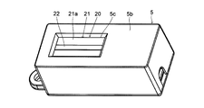
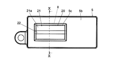
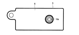
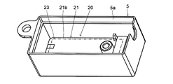
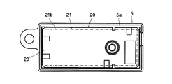
- FIGS. 7 to 9 are perspective views, a front view and a rear view of the ion sensor 20 and the case 5, and FIG. 10 is a vertical sectional side view of the ion sensor 20 and the case 5 shown in FIG. 11 and 12 are a perspective view and a rear view of the case 5 with the lid removed.
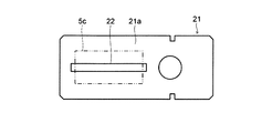
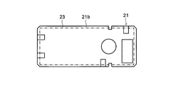
- 13 and 14 are a plan view showing a first surface of a circuit board of the ion sensor 20 and a plan view showing a second surface.
- the ion sensor 20 is built in the case 5 and includes a circuit board 21 as shown in FIGS. 7, 8, 11, and 12.
- the case 5 is a box-shaped member whose outer shape is a substantially rectangular parallelepiped shape, and one surface thereof opens as a main opening 5a.
- a lid 6 is attached to the main opening 5a of the case 5 and closed.
- the front surface 5b which is the other surface facing the main opening 5a of the case 5, is provided with a substantially rectangular electrode opening 5c that exposes a collecting electrode 22 to be described later to the outside of the case 5.
- the case 5 is disposed inside the main body housing 2 so that the front surface 5b having the electrode opening 5c is adjacent to the collection opening 2d of the main body housing 2 and the collecting electrode 22 faces the air circulation space.
- the lid 6 has a substantially rectangular shape in plan view covering the main opening 5a of the case 5 as shown in FIG.
- the lid 6 is fitted into the main opening 5a and is tightened by a screw 6a to seal the main opening 5a.
- a packing 7 shown in FIG. 10 is sandwiched between the lid 6 and the case 5.
- the packing 7 is made of, for example, ethylene-propylene-diene rubber (EPDM) in a rectangular ring shape, and seals the main opening 5a in a liquid-tight manner.
- EPDM ethylene-propylene-diene rubber
- the circuit board 21 includes a collecting electrode 22 on a first surface 21a (see FIGS. 10 and 13), and a circuit portion 23 on a second surface 21b (see FIGS. 10 and 14).
- the first surface 21 a and the second surface 21 b of the circuit board 21 form the front and back of the circuit board 21.
- the circuit board 21 is disposed inside the case 5 so that the first surface 21 a provided with the collecting electrode 22 is adjacent to the electrode opening 5 c of the case 5.
- the collecting electrode 22 is formed in a band shape and is affixed to the first surface 21 a of the circuit board 21.
- the collecting electrode 22 is disposed such that the longitudinal direction of the strip shape and the width direction perpendicular to the longitudinal direction coincide with the rectangular longitudinal and lateral directions of the electrode opening 5c.
- the collecting electrode 22 is longer in the longitudinal direction than the corresponding electrode opening 5c, and both end portions are not exposed to the outside from the electrode opening 5c.
- a packing 8 as a sealing member is sandwiched between the case 5 corresponding to the periphery of the electrode opening 5c and the first surface 21a of the circuit board 21 (see FIGS. 8 and 10).
- the packing 8 is formed of, for example, ethylene-propylene-diene rubber (EPDM) in a rectangular ring shape and seals the inside of the case 5 in a liquid-tight manner at the electrode opening 5c.
- EPDM ethylene-propylene-diene rubber
- the collecting electrode 22 and the packing 8 overlap with the first surface 21 a of the circuit board 21.
- the second surface 21b is liquid-tightly sealed while forming an air layer A1 on the surface of the second surface 21b of the circuit board 21.
- the collection electrode 22 having such a configuration collects ions released into the air by the ion generator 10 through the electrode opening 5c and the collection opening 2d.
- the circuit unit 23 is formed on the second surface 21 b of the circuit board 21 and is electrically connected to the collecting electrode 22.
- the circuit unit 23 operates to measure the amount of ions in the air using the collecting electrode 22.
- the circuit unit 23 transmits information related to the measured ion amount to an external control circuit, for example, via the terminal unit 4 of the main body housing 2.
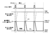
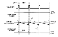
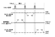
- FIGS. 15 to 17 are timing charts related to the ion amount measurement operation by the ion sensor 20.
- FIGS. 15 to 17 shows the waveform of the reset signal of the collecting electrode 22.
- the lower part of FIG. 15 to FIG. 17 shows an integrated waveform of the current generated when ions are brought into contact with the collecting electrode 22.
- the integrated waveform at the time of positive ion detection is drawn with a solid line, and the integrated waveform at the time of negative ion detection is drawn with a one-dot chain line. .
- the ion sensor 20 detects the electric charge per unit time generated by the ion touching the collecting electrode 22 as a current.
- a voltage corresponding to the amount of ions collected is obtained by satisfying the capacity of an integrator (not shown) provided in the circuit unit 23.
- the amount of ions can be measured by confirming this voltage after a predetermined time since the collection electrode 22 is reset.
- the collection electrode 22 is reset a predetermined number of times at regular intervals.
- the ion sensor 20 sets the voltage of the collecting electrode 22 to the reference voltage when the collecting electrode 22 is reset.
- the reference voltage is set to a substantially intermediate potential in the operating voltage range of the circuit unit 23. As shown in FIGS. 15 to 17, for example, when the operating voltage of the circuit unit 23 is 3.3V, the reference voltage is set to 1.6V.
- the voltage of the collection electrode 22 is a reference voltage, it means that the detected ion amount is zero.
- the amount of ions can be measured by deriving the difference (V2 ⁇ V1) between the voltage V1 of the collection electrode 22 at the reset and the voltage V2 of the collection electrode 22 after a predetermined time from the start of integration. .
- the integrated waveform when positive ions are detected in a relatively new state of the ion generator 12 is drawn with a solid line.
- the voltage of the collecting electrode 22 changes abruptly and reaches 0 V indicating that the amount of positive ions is appropriate.
- the change in the voltage of the collection electrode 22 after reset becomes gentle as shown in FIG. Furthermore, the state is such that the next reset is performed before reaching 0V indicating that the amount of positive ions is appropriate.
- the collecting electrode 22 and the packing 8 with respect to the first surface 21 a of the circuit board 21 on both ends of the collecting electrode 22. And overlap each other.
- the change in the voltage of the collecting electrode 22 after the reset can be abrupt with respect to the state shown in FIG. That is, the sensitivity of ion detection by the ion sensor 20 is improved.
- the ion generator 1 collects the ions generated by the ion generator 10 having the ion generator 12 that discharges ions into the air, and the circuit board 21 and the ions generated by the ion generator 10.
- the circuit part 23 provided on the second surface 21b of the circuit board 21 that operates to measure the amount of ions in the air using the collecting electrode 22 provided on the first surface 21a of the circuit board 21 to be collected.
- An ion sensor 20 having an ion generator 10 and an ion sensor 20, and a discharge opening 2 c that exposes the ion generator 12 to the outside and a collection opening 2 d that exposes the collection electrode 22 to the outside.
- a main body housing 2 disposed facing the air circulation space.
- the ion generator 1 liquid-tightly seals the 2nd surface 21b, ie, the circuit part 23, forming air layer A1 on the surface of the 2nd surface 21b of the circuit board 21.
- the circuit unit 23 can be in an air-insulated state. Therefore, it is possible to maintain an insulation state between circuit patterns.
- the ion generator 1 includes a case 5 containing the ion sensor 20, an electrode opening 5c that exposes the collecting electrode 22 to the outside of the case 5 provided in the case 5, and a case 5 corresponding to the periphery of the electrode opening 5c. And a packing 8 for liquid-tightly sealing the inside of the case 5 provided between the first surface 21a of the circuit board 21.
- the ion sensor 20 is built in the case 5, and only the collecting electrode 22 is exposed to the outside from the electrode opening 5 c, and the periphery of the electrode opening 5 c can be liquid-tightly sealed with the packing 8.
- the circuit portion 23 can be in an air-insulated state.
- the ion generator 1 can improve the sensitivity of ion detection by the ion sensor 20.
- the ion generator 1 includes a positive ion generator 12P that emits positive ions into the air, a negative ion generator 12N that discharges negative ions into the air, and a main body housing corresponding to the periphery of the collection opening 2d.
- the rib part 30 which is arrange
- the second rib 32 for introducing air into the collection opening 2d and the negative ion generation section 12N provided corresponding to the end on the side of the negative ion generation section 12N disposed far from the collection opening 2d.
- a shielding rib 33 for preventing inflow of negative ions emitted from the gas into the collection opening 2d.
- positive ions flowing through the first rib 31 along the air flow direction can be guided to the collecting electrode 22.
- positive ions staying in the stagnation portion of air in the direction in which the second rib 32 intersects the first rib 31 can be guided to the collecting electrode 22.
- the shielding rib 33 can prevent the negative ions that are not desired to be guided to the collecting electrode 22 from flowing into the collecting electrode 22. Therefore, it is possible to efficiently guide positive ions to be measured by the ion sensor 20 to the collecting electrode 22.
- the ion generator 1 is a device that is disposed facing at least a part of an air circulation space formed using polystyrene foam, and includes a positive ion generator 12P that discharges positive ions into the air.
- the ion sensor 20 is arrange
- the ion generator 1 includes a light emitting unit 40 that irradiates light to the outside of the main body housing 2, and the light emitting unit 40 is disposed on the downstream side of the negative ion generating unit 12N in the air flow direction. According to this configuration, charging of the light emitting unit 40 can be prevented. Therefore, accumulation of dust in the light emitting unit 40 can be suppressed, and light can be effectively irradiated to the outside of the main body housing 2.
- FIG. 18 is a vertical sectional top view of the ion sensor of the ion generator. Since the basic configuration of this embodiment is the same as that of the first embodiment described above, the same components as those of the first embodiment are denoted by the same reference numerals as before, and the description of the drawings and the description thereof. Shall be omitted.
- the ion sensor 20 includes a frame body 24 and a sealing resin 25 as shown in FIG.
- the frame body 24 is attached to the second surface 21 b of the circuit board 21.
- the frame body 24 has a ceiling portion 24a facing away from the second surface 21b and covers the entire circuit portion 23 provided on the second surface 21b.
- the frame body 24 forms an air layer A2 on the surface of the second surface 21b.
- Sealing resin 25 is provided around the frame body 24.
- the sealing resin 25 is made of a coating material having a moisture-proof function such as urethane.
- the sealing resin 25 is provided so as to cover the periphery of the frame body 24 after the frame body 24 is attached to the second surface 21 b of the circuit board 21.
- the second surface 21b can be liquid-tightly sealed with the sealing resin 25 while the air layer A2 is formed on the surface of the second surface 21b of the circuit board 21 using the frame body 24. it can. Therefore, it is possible to improve the action of liquid-tightly sealing the second surface 21b of the circuit board 21 while keeping the circuit portion 23 in an air-insulated state.
- FIG. 19 is a block diagram showing the configuration of the ion sensor of the ion generator
- FIG. 20 is a timing chart relating to the ion amount measurement operation by the ion sensor. Since the basic configuration of this embodiment is the same as that of the first embodiment described above, the same components as those of the first embodiment are denoted by the same reference numerals as before, and the description of the drawings and the description thereof. Shall be omitted.
- the circuit unit 23 of the ion sensor 20 includes an electrode setting unit 23a, an electrode voltage measurement unit 23b, a reference voltage determination unit 23c, and an output unit 23d as shown in FIG.
- the electrode setting unit 23a sets the voltage of the collecting electrode 22 to the reference voltage when the collecting electrode 22 is reset.
- the electrode setting unit 23a preferably sets the reference voltage in the vicinity of a substantially intermediate potential in the operating voltage range of the circuit unit 23 (see FIGS. 15 to 17). For example, when the operating voltage of the circuit unit 23 is 3.3V, the reference voltage is set to 1.6V.
- the electrode voltage measuring unit 23b measures the voltage of the collecting electrode 22.
- the amount of ions is measured by confirming the voltage of the collecting electrode 22 after a predetermined time from the resetting of the collecting electrode 22 (end of the integration period in FIGS. 15 to 17) (V2 ⁇ V1 ⁇ 0). With ions).
- the voltage of the collection electrode 22 should be close to the reference voltage as shown in FIGS.
- the reference voltage determination unit 23c uses the voltage of the collection electrode 22 measured by the electrode voltage measurement unit 23b immediately after the collection electrode 22 is reset and when the ion generator 10 is not performing the ion emission operation as the reference voltage. It is determined whether or not. Thereby, it is distinguished from the case where the ion generator 10 has abnormality or deterioration with time, and it is identified that the ion sensor 20 itself has abnormality.
- the ion sensor 20 sets the voltage of the collection electrode 22 to the reference voltage when the collection electrode 22 is reset, the ion generator 10 performs the ion emission operation immediately after the collection electrode 22 is reset. Abnormality of the ion sensor 20 can be identified by measuring the voltage of the collecting electrode 22 when there is not. Therefore, it is possible to distinguish between abnormality of the ion generator 10 or deterioration with time and abnormality of the ion sensor 20.
- the ion generator 1 is arranged facing the air circulation space formed using the polystyrene foam, but the installation location of the ion generator 1 is limited to such a form. It is not done.
- the said embodiment it arrange
- it comprised it may arrange
- the ion sensor 20 is built in the case 5 and sealed in a liquid-tight manner with respect to the outside. You may comprise so that it may seal liquid-tightly.
- the present invention can be used in an ion generator.
Landscapes
- Engineering & Computer Science (AREA)
- Chemical & Material Sciences (AREA)
- Combustion & Propulsion (AREA)
- Mechanical Engineering (AREA)
- General Engineering & Computer Science (AREA)
- Disinfection, Sterilisation Or Deodorisation Of Air (AREA)
Abstract
Description
最初に、本発明の第1実施形態に係るイオン発生装置について、図1~図6を用いてその構成を説明する。図1~図5はイオン発生装置の斜視図、正面図、上面図、側面図及び背面図である。図6はイオン発生装置の蓋を外した状態の背面図である。
H+(H2O)m+H+(H2O)m’+O2 -(H2O)n+O2 -(H2O)n’
→ 2・OH+O2+(m+m'+n+n')H2O ・・・(2)
H+(H2O)m+H+(H2O)m’+O2 -(H2O)n+O2 -(H2O)n’
→ H2O2+O2+(m+m'+n+n')H2O ・・・(3)
次に、本発明の第2実施形態に係るイオン発生装置について、図18を用いてその構成を説明する。図18はイオン発生装置のイオンセンサの垂直断面上面図である。なお、この実施形態の基本的な構成は先に説明した第1実施形態と同じであるので、第1実施形態と共通する構成要素には前と同じ符号を付し、図面の記載及びその説明を省略するものとする。
次に、本発明の第3実施形態に係るイオン発生装置について、図19及び図20を用いてその構成を説明する。図19はイオン発生装置のイオンセンサの構成を示すブロック図、図20はイオンセンサによるイオン量の測定動作に係るタイミングチャートである。なお、この実施形態の基本的な構成は先に説明した第1実施形態と同じであるので、第1実施形態と共通する構成要素には前と同じ符号を付し、図面の記載及びその説明を省略するものとする。
2 本体筐体
2c 放出開口
2d 捕集開口
5 ケース
5c 電極開口
8 パッキン(封止部材)
10 イオン発生器
10 イオン発生器
12 イオン発生部
12P 正イオン発生部
12N 負イオン発生部
20 イオンセンサ
21 回路基板
21a 第一面
21b 第二面
22 捕集電極
23 回路部
23a 電極設定部
23b 電極電圧測定部
23c 基準電圧判定部
23d 出力部
24 枠体
24a 天井部
25 封止樹脂
30 リブ部
31 第一リブ
32 第二リブ
33 遮蔽リブ
40 発光部
Claims (7)
- 空気中にイオンを放出するイオン発生部を有するイオン発生器と、
回路基板と前記イオン発生器が放出したイオンを捕集する前記回路基板の第一面に設けた捕集電極と前記捕集電極を用いて空気中のイオン量を測定するために動作する前記回路基板の第二面に設けた回路部とを有するイオンセンサと、
前記イオン発生器及び前記イオンセンサを内蔵するとともに前記イオン発生部を外部に露出する放出開口と前記捕集電極を外部に露出する捕集開口とを有して空気流通空間に臨んで配置される本体筐体と、
を備え、
前記回路基板の前記第二面の表面上に空気層を形成しながら前記第二面を液密に封止したことを特徴とするイオン発生装置。 - 前記イオンセンサを内蔵するケースと、
前記ケースに設けた前記ケースの外部に前記捕集電極を露出する電極開口と、
前記電極開口の周縁に対応する前記ケースと前記回路基板の前記第一面との間に設けた前記ケースの内側を液密に封止する封止部材と、
を備えることを特徴とする請求項1に記載のイオン発生装置。 - 前記回路基板の前記第一面に対して前記捕集電極と前記封止部材とが重なり合うことを特徴とする請求項2に記載のイオン発生装置。
- 前記回路基板の前記第二面に取り付けた前記第二面から離隔して対向する天井部を有する枠体と、
前記枠体の周囲を覆うように設けた封止樹脂と、
を備えることを特徴とする請求項1に記載のイオン発生装置。 - 空気中に正イオンを放出する正イオン発生部と、
空気中に負イオンを放出する負イオン発生部と、
前記捕集開口の周囲に対応する前記本体筐体の外面であって前記正イオン発生部及び前記負イオン発生部の少なくとも一方の空気流通方向下流側に配置されて空気流通空間に向かって突出するリブ部と、
を備え、
前記リブ部が、前記捕集開口の空気流通方向上流側及び下流側の各々において空気流通方向に沿って延びるよう形成された第一リブと、前記第一リブと交差する方向から前記捕集開口に空気を導入するための第二リブと、前記捕集開口に対して遠方に配置された前記正イオン発生部または前記負イオン発生部の側の端部に対応して設けられて前記遠方に配置されたイオン発生部が放出するイオンの前記捕集開口への流入を阻止するための遮蔽リブと、を備えることを特徴とする請求項1~請求項4のいずれか1項に記載のイオン発生装置。 - 少なくとも一部に発泡スチロールを利用して形成した前記空気流通空間に臨んで配置されるイオン発生装置であって、
空気中に正イオンを放出する正イオン発生部を備え、
前記イオンセンサが、前記正イオン発生部の空気流通方向下流側に配置されることを特徴とする請求項1~請求項5のいずれか1項に記載のイオン発生装置。 - 前記本体筐体の外部に対して光を照射する発光部を備え、
前記発光部が、前記イオン発生部の空気流通方向下流側に配置されることを特徴とする請求項1~請求項6のいずれか1項に記載のイオン発生装置。
Priority Applications (2)
| Application Number | Priority Date | Filing Date | Title |
|---|---|---|---|
| JP2015540416A JP6023346B2 (ja) | 2013-10-01 | 2014-08-06 | イオン発生装置 |
| CN201480043833.4A CN105453356B (zh) | 2013-10-01 | 2014-08-06 | 离子发生装置 |
Applications Claiming Priority (2)
| Application Number | Priority Date | Filing Date | Title |
|---|---|---|---|
| JP2013-206471 | 2013-10-01 | ||
| JP2013206471 | 2013-10-01 |
Publications (1)
| Publication Number | Publication Date |
|---|---|
| WO2015049920A1 true WO2015049920A1 (ja) | 2015-04-09 |
Family
ID=52778517
Family Applications (1)
| Application Number | Title | Priority Date | Filing Date |
|---|---|---|---|
| PCT/JP2014/070671 Ceased WO2015049920A1 (ja) | 2013-10-01 | 2014-08-06 | イオン発生装置 |
Country Status (3)
| Country | Link |
|---|---|
| JP (1) | JP6023346B2 (ja) |
| CN (1) | CN105453356B (ja) |
| WO (1) | WO2015049920A1 (ja) |
Cited By (1)
| Publication number | Priority date | Publication date | Assignee | Title |
|---|---|---|---|---|
| WO2017168800A1 (ja) * | 2016-03-28 | 2017-10-05 | シャープ株式会社 | イオン発生装置、及び、イオン発生装置の製造方法 |
Families Citing this family (2)
| Publication number | Priority date | Publication date | Assignee | Title |
|---|---|---|---|---|
| JP7029466B2 (ja) * | 2017-10-20 | 2022-03-03 | シャープ株式会社 | 放電装置 |
| IL262022B (en) * | 2018-09-27 | 2020-11-30 | Riskin Yefim | A method of air disinfection and disinfectant |
Citations (6)
| Publication number | Priority date | Publication date | Assignee | Title |
|---|---|---|---|---|
| JPS56151977U (ja) * | 1980-04-15 | 1981-11-13 | ||
| JP2004189147A (ja) * | 2002-12-12 | 2004-07-08 | Altia Co Ltd | 車両用マイナスイオン発生装置 |
| JP2011228075A (ja) * | 2010-04-19 | 2011-11-10 | Sharp Corp | イオン発生装置 |
| JP2012048867A (ja) * | 2010-08-24 | 2012-03-08 | Sharp Corp | イオン送出装置 |
| JP2012077923A (ja) * | 2010-09-30 | 2012-04-19 | Sharp Corp | 空気調和機 |
| JP2013031344A (ja) * | 2011-07-29 | 2013-02-07 | Sharp Corp | モータ制御装置、モータ制御方法及びイオン発生装置 |
Family Cites Families (3)
| Publication number | Priority date | Publication date | Assignee | Title |
|---|---|---|---|---|
| JP2002260820A (ja) * | 2001-02-27 | 2002-09-13 | Diamond Electric Mfg Co Ltd | イオン発生器とこれを備える電気機器 |
| CN2654404Y (zh) * | 2003-11-12 | 2004-11-10 | 周发崇 | 汽车负离子空气加湿器 |
| JP4769900B2 (ja) * | 2010-01-20 | 2011-09-07 | シャープ株式会社 | イオン発生装置及びその装置におけるイオン検出方法 |
-
2014
- 2014-08-06 WO PCT/JP2014/070671 patent/WO2015049920A1/ja not_active Ceased
- 2014-08-06 CN CN201480043833.4A patent/CN105453356B/zh not_active Expired - Fee Related
- 2014-08-06 JP JP2015540416A patent/JP6023346B2/ja not_active Expired - Fee Related
Patent Citations (6)
| Publication number | Priority date | Publication date | Assignee | Title |
|---|---|---|---|---|
| JPS56151977U (ja) * | 1980-04-15 | 1981-11-13 | ||
| JP2004189147A (ja) * | 2002-12-12 | 2004-07-08 | Altia Co Ltd | 車両用マイナスイオン発生装置 |
| JP2011228075A (ja) * | 2010-04-19 | 2011-11-10 | Sharp Corp | イオン発生装置 |
| JP2012048867A (ja) * | 2010-08-24 | 2012-03-08 | Sharp Corp | イオン送出装置 |
| JP2012077923A (ja) * | 2010-09-30 | 2012-04-19 | Sharp Corp | 空気調和機 |
| JP2013031344A (ja) * | 2011-07-29 | 2013-02-07 | Sharp Corp | モータ制御装置、モータ制御方法及びイオン発生装置 |
Cited By (3)
| Publication number | Priority date | Publication date | Assignee | Title |
|---|---|---|---|---|
| WO2017168800A1 (ja) * | 2016-03-28 | 2017-10-05 | シャープ株式会社 | イオン発生装置、及び、イオン発生装置の製造方法 |
| JPWO2017168800A1 (ja) * | 2016-03-28 | 2019-02-07 | シャープ株式会社 | イオン発生装置、及び、イオン発生装置の製造方法 |
| US10980909B2 (en) | 2016-03-28 | 2021-04-20 | Sharp Kabushiki Kaisha | Ion generating device and method for manufacturing ion generating device |
Also Published As
| Publication number | Publication date |
|---|---|
| JPWO2015049920A1 (ja) | 2017-03-09 |
| CN105453356B (zh) | 2017-03-15 |
| CN105453356A (zh) | 2016-03-30 |
| JP6023346B2 (ja) | 2016-11-09 |
Similar Documents
| Publication | Publication Date | Title |
|---|---|---|
| US10320160B2 (en) | Ion generation apparatus and electrical equipment | |
| CN102428324B (zh) | 离子产生装置 | |
| US9754757B2 (en) | Ion generation apparatus and electric equipment including the same | |
| EP3767733B1 (en) | Aerosol suction device | |
| US20150083931A1 (en) | Ion generating apparatus | |
| JP2010049829A (ja) | 除電器及び除電方法 | |
| US11458223B2 (en) | Discharge device and electric machine | |
| JP6023346B2 (ja) | イオン発生装置 | |
| CN112237301A (zh) | 气溶胶生成设备的供电单元和供电单元的控制方法 | |
| JPWO2018189928A1 (ja) | 放電装置および電気機器 | |
| WO2015050045A1 (ja) | イオン発生装置および電気機器 | |
| WO2010143491A1 (ja) | イオン発生装置 | |
| JP2017009202A (ja) | 送風装置 | |
| KR100805225B1 (ko) | 살균장치 및 이온발생장치 | |
| JP2007141692A (ja) | イオン化装置 | |
| JP4411356B1 (ja) | イオン検出装置及びそれを備えたイオン発生装置 | |
| JP2013218852A (ja) | 帯電粒子発生装置 | |
| TWI624194B (zh) | Ion generator | |
| JP6334152B2 (ja) | イオン発生装置 | |
| CN109997035B (zh) | 氧传感器的排气方法 | |
| CN202651619U (zh) | 离子产生装置 | |
| KR102530020B1 (ko) | 염습도 측정 기반 안전 관리 장치가 구비된 태양광발전시스템 | |
| JP2009279557A (ja) | イオン壁形成装置 | |
| JP4842151B2 (ja) | 除電装置 | |
| JP2006107778A (ja) | 除電装置 |
Legal Events
| Date | Code | Title | Description |
|---|---|---|---|
| WWE | Wipo information: entry into national phase |
Ref document number: 201480043833.4 Country of ref document: CN |
|
| 121 | Ep: the epo has been informed by wipo that ep was designated in this application |
Ref document number: 14851047 Country of ref document: EP Kind code of ref document: A1 |
|
| ENP | Entry into the national phase |
Ref document number: 2015540416 Country of ref document: JP Kind code of ref document: A |
|
| NENP | Non-entry into the national phase |
Ref country code: DE |
|
| 122 | Ep: pct application non-entry in european phase |
Ref document number: 14851047 Country of ref document: EP Kind code of ref document: A1 |