EP3767733B1 - Aerosol suction device - Google Patents
Aerosol suction device Download PDFInfo
- Publication number
- EP3767733B1 EP3767733B1 EP20186210.9A EP20186210A EP3767733B1 EP 3767733 B1 EP3767733 B1 EP 3767733B1 EP 20186210 A EP20186210 A EP 20186210A EP 3767733 B1 EP3767733 B1 EP 3767733B1
- Authority
- EP
- European Patent Office
- Prior art keywords
- power supply
- electrostatic capacitance
- controller
- electrolytic solution
- aerosol
- Prior art date
- Legal status (The legal status is an assumption and is not a legal conclusion. Google has not performed a legal analysis and makes no representation as to the accuracy of the status listed.)
- Active
Links
- 239000000443 aerosol Substances 0.000 title claims description 91
- 239000007788 liquid Substances 0.000 claims description 87
- 239000008151 electrolyte solution Substances 0.000 claims description 77
- XLYOFNOQVPJJNP-UHFFFAOYSA-N water Substances O XLYOFNOQVPJJNP-UHFFFAOYSA-N 0.000 claims description 35
- 238000007599 discharging Methods 0.000 claims description 10
- 238000001514 detection method Methods 0.000 description 25
- 239000000796 flavoring agent Substances 0.000 description 18
- 235000019634 flavors Nutrition 0.000 description 18
- 239000003990 capacitor Substances 0.000 description 14
- 238000010586 diagram Methods 0.000 description 10
- DNIAPMSPPWPWGF-UHFFFAOYSA-N Propylene glycol Chemical compound CC(O)CO DNIAPMSPPWPWGF-UHFFFAOYSA-N 0.000 description 9
- IAZDPXIOMUYVGZ-UHFFFAOYSA-N Dimethylsulphoxide Chemical compound CS(C)=O IAZDPXIOMUYVGZ-UHFFFAOYSA-N 0.000 description 8
- 238000012545 processing Methods 0.000 description 7
- 238000000034 method Methods 0.000 description 6
- 238000010438 heat treatment Methods 0.000 description 5
- 239000011259 mixed solution Substances 0.000 description 5
- 229920000742 Cotton Polymers 0.000 description 4
- PEDCQBHIVMGVHV-UHFFFAOYSA-N Glycerine Chemical compound OCC(O)CO PEDCQBHIVMGVHV-UHFFFAOYSA-N 0.000 description 4
- JBTWLSYIZRCDFO-UHFFFAOYSA-N ethyl methyl carbonate Chemical compound CCOC(=O)OC JBTWLSYIZRCDFO-UHFFFAOYSA-N 0.000 description 4
- RUOJZAUFBMNUDX-UHFFFAOYSA-N propylene carbonate Chemical compound CC1COC(=O)O1 RUOJZAUFBMNUDX-UHFFFAOYSA-N 0.000 description 4
- 241000208125 Nicotiana Species 0.000 description 3
- 235000002637 Nicotiana tabacum Nutrition 0.000 description 3
- OIFBSDVPJOWBCH-UHFFFAOYSA-N Diethyl carbonate Chemical compound CCOC(=O)OCC OIFBSDVPJOWBCH-UHFFFAOYSA-N 0.000 description 2
- KMTRUDSVKNLOMY-UHFFFAOYSA-N Ethylene carbonate Chemical compound O=C1OCCO1 KMTRUDSVKNLOMY-UHFFFAOYSA-N 0.000 description 2
- 230000005856 abnormality Effects 0.000 description 2
- 238000000889 atomisation Methods 0.000 description 2
- 230000005540 biological transmission Effects 0.000 description 2
- 239000000919 ceramic Substances 0.000 description 2
- 238000002485 combustion reaction Methods 0.000 description 2
- 238000004891 communication Methods 0.000 description 2
- 239000003989 dielectric material Substances 0.000 description 2
- IEJIGPNLZYLLBP-UHFFFAOYSA-N dimethyl carbonate Chemical compound COC(=O)OC IEJIGPNLZYLLBP-UHFFFAOYSA-N 0.000 description 2
- 239000003571 electronic cigarette Substances 0.000 description 2
- 235000011187 glycerol Nutrition 0.000 description 2
- 235000008216 herbs Nutrition 0.000 description 2
- 239000000463 material Substances 0.000 description 2
- 239000005486 organic electrolyte Substances 0.000 description 2
- 239000002994 raw material Substances 0.000 description 2
- 239000011347 resin Substances 0.000 description 2
- 229920005989 resin Polymers 0.000 description 2
- 238000007789 sealing Methods 0.000 description 2
- NOOLISFMXDJSKH-UTLUCORTSA-N (+)-Neomenthol Chemical compound CC(C)[C@@H]1CC[C@@H](C)C[C@@H]1O NOOLISFMXDJSKH-UTLUCORTSA-N 0.000 description 1
- RNFJDJUURJAICM-UHFFFAOYSA-N 2,2,4,4,6,6-hexaphenoxy-1,3,5-triaza-2$l^{5},4$l^{5},6$l^{5}-triphosphacyclohexa-1,3,5-triene Chemical compound N=1P(OC=2C=CC=CC=2)(OC=2C=CC=CC=2)=NP(OC=2C=CC=CC=2)(OC=2C=CC=CC=2)=NP=1(OC=1C=CC=CC=1)OC1=CC=CC=C1 RNFJDJUURJAICM-UHFFFAOYSA-N 0.000 description 1
- NOOLISFMXDJSKH-UHFFFAOYSA-N DL-menthol Natural products CC(C)C1CCC(C)CC1O NOOLISFMXDJSKH-UHFFFAOYSA-N 0.000 description 1
- 241000196324 Embryophyta Species 0.000 description 1
- HBBGRARXTFLTSG-UHFFFAOYSA-N Lithium ion Chemical compound [Li+] HBBGRARXTFLTSG-UHFFFAOYSA-N 0.000 description 1
- 235000006679 Mentha X verticillata Nutrition 0.000 description 1
- 235000002899 Mentha suaveolens Nutrition 0.000 description 1
- 235000001636 Mentha x rotundifolia Nutrition 0.000 description 1
- 229910000831 Steel Inorganic materials 0.000 description 1
- 230000002159 abnormal effect Effects 0.000 description 1
- 239000000654 additive Substances 0.000 description 1
- 230000000996 additive effect Effects 0.000 description 1
- 229910052782 aluminium Inorganic materials 0.000 description 1
- XAGFODPZIPBFFR-UHFFFAOYSA-N aluminium Chemical compound [Al] XAGFODPZIPBFFR-UHFFFAOYSA-N 0.000 description 1
- 239000000872 buffer Substances 0.000 description 1
- 230000001419 dependent effect Effects 0.000 description 1
- 229940079593 drug Drugs 0.000 description 1
- 239000003814 drug Substances 0.000 description 1
- 238000005485 electric heating Methods 0.000 description 1
- 239000003792 electrolyte Substances 0.000 description 1
- 230000005674 electromagnetic induction Effects 0.000 description 1
- 239000003063 flame retardant Substances 0.000 description 1
- 239000012530 fluid Substances 0.000 description 1
- 239000003365 glass fiber Substances 0.000 description 1
- 230000006698 induction Effects 0.000 description 1
- 239000002608 ionic liquid Substances 0.000 description 1
- 229910001416 lithium ion Inorganic materials 0.000 description 1
- 229910003002 lithium salt Inorganic materials 0.000 description 1
- 159000000002 lithium salts Chemical class 0.000 description 1
- 229940041616 menthol Drugs 0.000 description 1
- 229910052751 metal Inorganic materials 0.000 description 1
- 239000002184 metal Substances 0.000 description 1
- 239000000203 mixture Substances 0.000 description 1
- 238000000465 moulding Methods 0.000 description 1
- 239000003960 organic solvent Substances 0.000 description 1
- 230000002093 peripheral effect Effects 0.000 description 1
- 230000000704 physical effect Effects 0.000 description 1
- 239000002985 plastic film Substances 0.000 description 1
- 229920006255 plastic film Polymers 0.000 description 1
- 230000004044 response Effects 0.000 description 1
- 239000004065 semiconductor Substances 0.000 description 1
- 239000007787 solid Substances 0.000 description 1
- 239000007784 solid electrolyte Substances 0.000 description 1
- 239000000243 solution Substances 0.000 description 1
- 238000001179 sorption measurement Methods 0.000 description 1
- 239000010959 steel Substances 0.000 description 1
- 239000000126 substance Substances 0.000 description 1
- 238000012546 transfer Methods 0.000 description 1
- 238000013519 translation Methods 0.000 description 1
- 230000032258 transport Effects 0.000 description 1
Images


Classifications
-
- A—HUMAN NECESSITIES
- A24—TOBACCO; CIGARS; CIGARETTES; SIMULATED SMOKING DEVICES; SMOKERS' REQUISITES
- A24F—SMOKERS' REQUISITES; MATCH BOXES; SIMULATED SMOKING DEVICES
- A24F40/00—Electrically operated smoking devices; Component parts thereof; Manufacture thereof; Maintenance or testing thereof; Charging means specially adapted therefor
- A24F40/90—Arrangements or methods specially adapted for charging batteries thereof
-
- A—HUMAN NECESSITIES
- A24—TOBACCO; CIGARS; CIGARETTES; SIMULATED SMOKING DEVICES; SMOKERS' REQUISITES
- A24F—SMOKERS' REQUISITES; MATCH BOXES; SIMULATED SMOKING DEVICES
- A24F40/00—Electrically operated smoking devices; Component parts thereof; Manufacture thereof; Maintenance or testing thereof; Charging means specially adapted therefor
- A24F40/50—Control or monitoring
-
- A—HUMAN NECESSITIES
- A24—TOBACCO; CIGARS; CIGARETTES; SIMULATED SMOKING DEVICES; SMOKERS' REQUISITES
- A24F—SMOKERS' REQUISITES; MATCH BOXES; SIMULATED SMOKING DEVICES
- A24F40/00—Electrically operated smoking devices; Component parts thereof; Manufacture thereof; Maintenance or testing thereof; Charging means specially adapted therefor
- A24F40/40—Constructional details, e.g. connection of cartridges and battery parts
- A24F40/48—Fluid transfer means, e.g. pumps
- A24F40/485—Valves; Apertures
-
- A—HUMAN NECESSITIES
- A24—TOBACCO; CIGARS; CIGARETTES; SIMULATED SMOKING DEVICES; SMOKERS' REQUISITES
- A24F—SMOKERS' REQUISITES; MATCH BOXES; SIMULATED SMOKING DEVICES
- A24F40/00—Electrically operated smoking devices; Component parts thereof; Manufacture thereof; Maintenance or testing thereof; Charging means specially adapted therefor
- A24F40/50—Control or monitoring
- A24F40/51—Arrangement of sensors
-
- A—HUMAN NECESSITIES
- A24—TOBACCO; CIGARS; CIGARETTES; SIMULATED SMOKING DEVICES; SMOKERS' REQUISITES
- A24F—SMOKERS' REQUISITES; MATCH BOXES; SIMULATED SMOKING DEVICES
- A24F40/00—Electrically operated smoking devices; Component parts thereof; Manufacture thereof; Maintenance or testing thereof; Charging means specially adapted therefor
- A24F40/50—Control or monitoring
- A24F40/53—Monitoring, e.g. fault detection
-
- A—HUMAN NECESSITIES
- A24—TOBACCO; CIGARS; CIGARETTES; SIMULATED SMOKING DEVICES; SMOKERS' REQUISITES
- A24F—SMOKERS' REQUISITES; MATCH BOXES; SIMULATED SMOKING DEVICES
- A24F47/00—Smokers' requisites not otherwise provided for
-
- A—HUMAN NECESSITIES
- A61—MEDICAL OR VETERINARY SCIENCE; HYGIENE
- A61M—DEVICES FOR INTRODUCING MEDIA INTO, OR ONTO, THE BODY; DEVICES FOR TRANSDUCING BODY MEDIA OR FOR TAKING MEDIA FROM THE BODY; DEVICES FOR PRODUCING OR ENDING SLEEP OR STUPOR
- A61M15/00—Inhalators
- A61M15/06—Inhaling appliances shaped like cigars, cigarettes or pipes
-
- G—PHYSICS
- G01—MEASURING; TESTING
- G01M—TESTING STATIC OR DYNAMIC BALANCE OF MACHINES OR STRUCTURES; TESTING OF STRUCTURES OR APPARATUS, NOT OTHERWISE PROVIDED FOR
- G01M3/00—Investigating fluid-tightness of structures
- G01M3/02—Investigating fluid-tightness of structures by using fluid or vacuum
- G01M3/04—Investigating fluid-tightness of structures by using fluid or vacuum by detecting the presence of fluid at the leakage point
- G01M3/16—Investigating fluid-tightness of structures by using fluid or vacuum by detecting the presence of fluid at the leakage point using electric detection means
- G01M3/18—Investigating fluid-tightness of structures by using fluid or vacuum by detecting the presence of fluid at the leakage point using electric detection means for pipes, cables or tubes; for pipe joints or seals; for valves; for welds; for containers, e.g. radiators
- G01M3/186—Investigating fluid-tightness of structures by using fluid or vacuum by detecting the presence of fluid at the leakage point using electric detection means for pipes, cables or tubes; for pipe joints or seals; for valves; for welds; for containers, e.g. radiators for containers, e.g. radiators
-
- H—ELECTRICITY
- H01—ELECTRIC ELEMENTS
- H01M—PROCESSES OR MEANS, e.g. BATTERIES, FOR THE DIRECT CONVERSION OF CHEMICAL ENERGY INTO ELECTRICAL ENERGY
- H01M10/00—Secondary cells; Manufacture thereof
- H01M10/05—Accumulators with non-aqueous electrolyte
- H01M10/052—Li-accumulators
- H01M10/0525—Rocking-chair batteries, i.e. batteries with lithium insertion or intercalation in both electrodes; Lithium-ion batteries
-
- H—ELECTRICITY
- H01—ELECTRIC ELEMENTS
- H01M—PROCESSES OR MEANS, e.g. BATTERIES, FOR THE DIRECT CONVERSION OF CHEMICAL ENERGY INTO ELECTRICAL ENERGY
- H01M10/00—Secondary cells; Manufacture thereof
- H01M10/42—Methods or arrangements for servicing or maintenance of secondary cells or secondary half-cells
- H01M10/4228—Leak testing of cells or batteries
-
- H—ELECTRICITY
- H01—ELECTRIC ELEMENTS
- H01M—PROCESSES OR MEANS, e.g. BATTERIES, FOR THE DIRECT CONVERSION OF CHEMICAL ENERGY INTO ELECTRICAL ENERGY
- H01M10/00—Secondary cells; Manufacture thereof
- H01M10/42—Methods or arrangements for servicing or maintenance of secondary cells or secondary half-cells
- H01M10/425—Structural combination with electronic components, e.g. electronic circuits integrated to the outside of the casing
-
- H—ELECTRICITY
- H01—ELECTRIC ELEMENTS
- H01M—PROCESSES OR MEANS, e.g. BATTERIES, FOR THE DIRECT CONVERSION OF CHEMICAL ENERGY INTO ELECTRICAL ENERGY
- H01M10/00—Secondary cells; Manufacture thereof
- H01M10/42—Methods or arrangements for servicing or maintenance of secondary cells or secondary half-cells
- H01M10/48—Accumulators combined with arrangements for measuring, testing or indicating the condition of cells, e.g. the level or density of the electrolyte
- H01M10/488—Cells or batteries combined with indicating means for external visualization of the condition, e.g. by change of colour or of light density
-
- H—ELECTRICITY
- H02—GENERATION; CONVERSION OR DISTRIBUTION OF ELECTRIC POWER
- H02J—CIRCUIT ARRANGEMENTS OR SYSTEMS FOR SUPPLYING OR DISTRIBUTING ELECTRIC POWER; SYSTEMS FOR STORING ELECTRIC ENERGY
- H02J7/00—Circuit arrangements for charging or depolarising batteries or for supplying loads from batteries
- H02J7/0063—Circuit arrangements for charging or depolarising batteries or for supplying loads from batteries with circuits adapted for supplying loads from the battery
-
- A—HUMAN NECESSITIES
- A24—TOBACCO; CIGARS; CIGARETTES; SIMULATED SMOKING DEVICES; SMOKERS' REQUISITES
- A24F—SMOKERS' REQUISITES; MATCH BOXES; SIMULATED SMOKING DEVICES
- A24F40/00—Electrically operated smoking devices; Component parts thereof; Manufacture thereof; Maintenance or testing thereof; Charging means specially adapted therefor
- A24F40/10—Devices using liquid inhalable precursors
-
- A—HUMAN NECESSITIES
- A24—TOBACCO; CIGARS; CIGARETTES; SIMULATED SMOKING DEVICES; SMOKERS' REQUISITES
- A24F—SMOKERS' REQUISITES; MATCH BOXES; SIMULATED SMOKING DEVICES
- A24F40/00—Electrically operated smoking devices; Component parts thereof; Manufacture thereof; Maintenance or testing thereof; Charging means specially adapted therefor
- A24F40/30—Devices using two or more structurally separated inhalable precursors, e.g. using two liquid precursors in two cartridges
-
- A—HUMAN NECESSITIES
- A61—MEDICAL OR VETERINARY SCIENCE; HYGIENE
- A61M—DEVICES FOR INTRODUCING MEDIA INTO, OR ONTO, THE BODY; DEVICES FOR TRANSDUCING BODY MEDIA OR FOR TAKING MEDIA FROM THE BODY; DEVICES FOR PRODUCING OR ENDING SLEEP OR STUPOR
- A61M2205/00—General characteristics of the apparatus
- A61M2205/15—Detection of leaks
-
- H—ELECTRICITY
- H01—ELECTRIC ELEMENTS
- H01M—PROCESSES OR MEANS, e.g. BATTERIES, FOR THE DIRECT CONVERSION OF CHEMICAL ENERGY INTO ELECTRICAL ENERGY
- H01M10/00—Secondary cells; Manufacture thereof
- H01M10/42—Methods or arrangements for servicing or maintenance of secondary cells or secondary half-cells
- H01M10/425—Structural combination with electronic components, e.g. electronic circuits integrated to the outside of the casing
- H01M2010/4271—Battery management systems including electronic circuits, e.g. control of current or voltage to keep battery in healthy state, cell balancing
-
- H—ELECTRICITY
- H01—ELECTRIC ELEMENTS
- H01M—PROCESSES OR MEANS, e.g. BATTERIES, FOR THE DIRECT CONVERSION OF CHEMICAL ENERGY INTO ELECTRICAL ENERGY
- H01M2220/00—Batteries for particular applications
- H01M2220/30—Batteries in portable systems, e.g. mobile phone, laptop
-
- H—ELECTRICITY
- H02—GENERATION; CONVERSION OR DISTRIBUTION OF ELECTRIC POWER
- H02J—CIRCUIT ARRANGEMENTS OR SYSTEMS FOR SUPPLYING OR DISTRIBUTING ELECTRIC POWER; SYSTEMS FOR STORING ELECTRIC ENERGY
- H02J7/00—Circuit arrangements for charging or depolarising batteries or for supplying loads from batteries
- H02J7/02—Circuit arrangements for charging or depolarising batteries or for supplying loads from batteries for charging batteries from ac mains by converters
-
- Y—GENERAL TAGGING OF NEW TECHNOLOGICAL DEVELOPMENTS; GENERAL TAGGING OF CROSS-SECTIONAL TECHNOLOGIES SPANNING OVER SEVERAL SECTIONS OF THE IPC; TECHNICAL SUBJECTS COVERED BY FORMER USPC CROSS-REFERENCE ART COLLECTIONS [XRACs] AND DIGESTS
- Y02—TECHNOLOGIES OR APPLICATIONS FOR MITIGATION OR ADAPTATION AGAINST CLIMATE CHANGE
- Y02E—REDUCTION OF GREENHOUSE GAS [GHG] EMISSIONS, RELATED TO ENERGY GENERATION, TRANSMISSION OR DISTRIBUTION
- Y02E60/00—Enabling technologies; Technologies with a potential or indirect contribution to GHG emissions mitigation
- Y02E60/10—Energy storage using batteries
Definitions
- the present disclosure relates to an aerosol suction device having a power supply unit.
- Patent Literature 1 Japanese Translation of PCT International Application Publication No. JP-T-2016-536023 discloses a personal electronic inhaler including a power supply such as a battery, an atomizer that may include one or a plurality of heating element(s), and a bulkhead for separating a battery from an atomizer region. According to such a personal electronic inhaler, when an electrolytic solution leaks from the battery, the bulkhead can prevent the electrolytic solution from flowing out to an atomizer side.
- a power supply such as a battery
- an atomizer that may include one or a plurality of heating element(s)
- a bulkhead for separating a battery from an atomizer region. According to such a personal electronic inhaler, when an electrolytic solution leaks from the battery, the bulkhead can prevent the electrolytic solution from flowing out to an atomizer side.
- Patent Literature 2 Description of Chinese Patent Publication No. 103099319 (hereinafter, referred to as Patent Literature 2) discloses a sealing layer that prevents outflow of an electrolytic solution and an adsorption layer that adsorbs the electrolytic solution when the outflow of the electrolytic solution cannot be stopped by the sealing layer.
- Patent Literature 3 discloses an electronic cigarette in which a housing made of aluminum and a plastic film is provided in a housing made of steel in order to prevent an electrolytic solution from flowing out to outside.
- Patent Literatures 1 to 3 although a method is disclosed which prevents other components from being influenced when the electrolytic solution leaks from the battery, the leakage of the electrolytic solution from the battery cannot be recognized. In other words, even after the electrolytic solution leaks, an operation of the personal electronic inhaler or the like is continued.
- Patent Literatures 1 to 3 when a liquid enters into the housing due to submersion or the like, the entering of the liquid cannot be recognized.
- a power supply unit of an aerosol generation apparatus it is important to recognize a state that may influence an operation of the aerosol generation apparatus, such as the leakage of the liquid, the entering of the liquid, a bulge of the power supply (cell), and the like.
- An object of the present disclosure is to provide an aerosol suction device comprising a power supply unit that can accurately diagnose a state of the power supply unit.
- EP 3 476 645 A1 discloses a vehicle battery safety sensor system. It proposes to mount batteries into an enclosure (so-called “battery cell bay 26") that comprises a "low point area 32" where any liquid could accumulate in a case of spillage. It is in this area, where the corresponding teaching proposes to provide a "first sensor 36".
- JP H10-012284 A refers to possible leakage from an organic electrolyte battery and proposes a detection electrode "2". A current will flow through this electrode once an insulating film is fused by leaked organic electrolyte.
- EP 3 072 406 A1 discloses an electronic cigarette and specifically proposes a capacitive sensor for sensing a pressure differential. The teaching claims that capacitive pressure sensors are more precise and sensitive than mechanical sensors.
- the present invention provides the subject-matter of the independent claim. Further preferred embodiments are defined in the dependent claims.
- the influence of at least one of the leakage of the liquid and the entering of the liquid can be avoided.
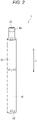
- An aerosol suction device 1 is a device for suctioning a flavor without combustion and has a rod shape that extends along a predetermined direction (hereinafter, referred to as a longitudinal direction A). As shown in Figs. 1 and 2 , the aerosol suction device 1 is provided with a power supply unit 10, a first cartridge 20, and a second cartridge 30 in this order along the longitudinal direction A. The first cartridge 20 is attachable to and detachable from the power supply unit 10, and the second cartridge 30 is attachable to and detachable from the first cartridge 20. In other words, the first cartridge 20 and the second cartridge 30 can be replaced with each other.
- the power supply unit 10 of the present embodiment houses a power supply 12, a charger 13, a controller 50, various sensors, and the like inside a cylindrical power supply unit case 11.
- the power supply 12 is a rechargeable secondary battery, and preferably a lithium-ion secondary battery.
- the power supply 12 of the present embodiment includes a cylindrical case 12a that houses various components such as an electrode and an electrolytic solution (not shown).
- a pair of tabs 12b serving as positive and negative electrodes are provided at one end portion or both end portions of the power supply 12 in a length direction (longitudinal direction A).
- the positive electrode tab 12b may be provided on one end of both ends of the power supply 12 in the length direction
- the positive electrode tab 12b may be provided on the other end of both ends of the power supply 12 in the length direction.
- both the positive electrode tab 12b and the negative electrode tab 12b may be provided on one end of the power supply 12 in the length direction.
- the power supply 12 includes a safety valve (not shown) that opens when an internal pressure of the power supply 12 is larger than a predetermined pressure, on one end portion or both end portions in the length direction.
- a discharge terminal 41 is provided on a top portion 11a positioned on one end side (first cartridge 20 side) of the power supply unit case 11 in the longitudinal direction A.
- the discharge terminal 41 protrudes from an upper surface of the top portion 11a toward the first cartridge 20 and can be electrically connected to a load 21 of the first cartridge 20.
- An air supply portion 42 that supplies air to the load 21 of the first cartridge 20 is provided in the vicinity of the discharge terminal 41 on the upper surface of the top portion 11a.
- a charging terminal 43 that can be electrically connected to an external power supply 60 (see Fig. 5 ) that can charge the power supply 12 is provided inside a bottom portion 11b positioned on the other end side (side opposite to the first cartridge 20) of the power supply unit case 11 in the longitudinal direction A.
- the charging terminal 43 is provided inside a side surface of the bottom portion 11b, and at least one of a USB terminal, a microUSB terminal, and a Lightning (registered trademark) terminal can be connected to the charging terminal 43.
- the charging terminal 43 may be a power receiving unit that can receive, in a wireless manner, power supplied from the external power supply 60.
- the charging terminal 43 (power receiving unit) may be configured with a power receiving coil.
- a method for the wireless power transfer may be electromagnetic induction or magnetic resonance.
- the charging terminal 43 may be a power receiving unit that can receive, without contact, the power supplied from the external power supply 60.
- at least one of the USB terminal, the microUSB terminal, and the Lightning (registered trademark) terminal can be connected to the charging terminal 43, and the charging terminal 43 may include the above-described power receiving unit.
- the power supply unit 10 is configured such that the external power supply 60 can be electrically connected to the charging terminal 43 in a state where the power supply 12 can be discharged via the discharge terminal 41. Further, in the power supply unit 10, when an aerosol generation request is detected while the charging terminal 43 and the external power supply 60 are electrically connected, simultaneous charging and discharging of the power supply 12 is prohibited.
- the power supply unit case 11 is provided with an operation unit 14 that can be operated by a user, on a side surface of the top portion 11a, so as to face a side opposite to the charging terminal 43. More specifically, the operation unit 14 and the charging terminal 43 are in a point-symmetrical relationship with an intersection of a straight line that connects the operation unit 14 to the charging terminal 43 and a center line L of the power supply unit 10 in the longitudinal direction A.
- the operation unit 14 is configured with a button type switch, a touch panel, and the like and is used when a use intention of the user is reflected so as to activate/interrupt the controller 50 and various sensors.
- the controller 50 and an intake sensor 15 that detects a puff operation are provided in the vicinity of the operation unit 14.
- the charger 13 controls charging power input from the charging terminal 43 to the power supply 12.
- the charger 13 is configured by using a charging IC that is mounted on a charging cable connected to the charging terminal 43 and that includes a converter that converts a direct current from an inverter 61 or the like into a direct current having different magnitude, a voltmeter, an ammeter, a processor, and the like.
- the inverter 61 or the like converts an alternating current into a direct current.
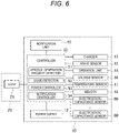
- the controller 50 is connected to the charger 13, the operation unit 14, various sensor devices such as the intake sensor 15 that detects the puff (intake) operation, a voltage sensor 16 that measures a voltage of the power supply 12, a temperature sensor 17 that detects a temperature, an electrostatic capacitance sensor 80 that is separate from the intake sensor 15 and detects electrostatic capacitance inside the power supply unit case 11, and a memory 18 that stores the number of puff operations, time for energizing the load 21, or the like, and performs various controls of the aerosol suction device 1.
- the intake sensor 15 may be configured with a condenser microphone, a pressure sensor, or the like.
- the controller 50 is a processor (MCU: Micro Controller Unit). More specifically, the structure of the processor is an electric circuit in which circuit elements such as semiconductor elements are combined. Details of the controller 50 will be described later.
- the power supply unit case 11 is provided with an air intake port 11c that takes outside air into inside thereof.
- the air intake port 11c may be provided around the operation unit 14 or may be provided around the charging terminal 43.
- the first cartridge 20 includes, inside a cylindrical cartridge case 27, a reservoir 23 that stores an aerosol source 22, the electrical load 21 that atomizes the aerosol source 22, a wick 24 that draws the aerosol source from the reservoir 23 into the load 21, an aerosol flow path 25 that causes an aerosol generated by the atomization of the aerosol source 22 to flow toward the second cartridge 30, and an end cap 26 that houses a part of the second cartridge 30.
- the reservoir 23 is partitioned and formed so as to surround a periphery of the aerosol flow path 25 and stores the aerosol source 22.
- a porous body such as a resin web or cotton may be housed in the reservoir 23, and the aerosol source 22 may be impregnated in the porous body.
- the porous body on the resin web or the cotton may not be housed and only the aerosol source 22 may be stored.
- the aerosol source 22 contains liquids such as glycerin, propylene glycol, and water.
- the wick 24 is a liquid holding member that draws the aerosol source 22 from the reservoir 23 into the load 21 by using a capillary phenomenon, and is configured with, for example, glass fiber or porous ceramic.
- the load 21 atomizes the aerosol source 22 without combustion by power supplied from the power supply 12 via the discharge terminal 41.
- the load 21 is configured with an electric heating wire (coil) wound at a predetermined pitch.
- the load 21 may be an element that can atomize the aerosol source 22 so as to generate an aerosol, and is, for example, a heating element or an ultrasonic generator. Examples of the heating element include a heating resistor, a ceramic heater, and an induction heating heater.
- the aerosol flow path 25 is downstream of the load 21 and provided on the center line L of the power supply unit 10.
- the end cap 26 includes a cartridge housing portion 26a that houses a part of the second cartridge 30, and a communication path 26b that communicates the aerosol flow path 25 with the cartridge housing portion 26a.
- the second cartridge 30 stores a flavor source 31.
- the second cartridge 30 is detachably housed in the cartridge housing portion 26a provided in the end cap 26 of the first cartridge 20.
- An end portion of the second cartridge 30 on a side opposite to a first cartridge 20 side is a suction port 32 of the user.
- the suction port 32 is not limited to the case of being integrally formed with the second cartridge 30 and may be configured to be attachable to and detachable from the second cartridge 30. Accordingly, the suction port 32 is separate from the power supply unit 10 and the first cartridge 20, so that the suction port 32 can be kept hygienic.
- the second cartridge 30 causes an aerosol generated by atomizing the aerosol source 22 by the load 21 to pass through the flavor source 31, so that a flavor is given to the aerosol.
- a raw material piece that constitutes the flavor source 31 a molded body obtained by molding shredded tobacco or a tobacco raw material into a granular shape can be used.
- the flavor source 31 may be configured with a plant other than tobacco (for example, mint, Chinese herbs, herbs, or the like). A flavor material such as menthol may be given to the flavor source 31.
- the aerosol source 22, the flavor source 31, and the load 21 can generate an aerosol to which a flavor is added. That is, the aerosol source 22 and the flavor source 31 can be referred to as an aerosol generation source that generates an aerosol.
- the configuration of the aerosol generation source used in the aerosol suction device 1 may be a configuration in which the aerosol source 22 and the flavor source 31 are integrally formed, a configuration in which the flavor source 31 is omitted and a substance that may be contained in the flavor source 31 is added to the aerosol source 22, a configuration in which a medication or the like is added to the aerosol source 22 instead of the flavor source 31, or the like.
- air that flows in from the air intake port 11c provided in the power supply unit case 11 passes near the load 21 of the first cartridge 20 from the air supply portion 42.
- the load 21 atomizes the aerosol source 22 drawn or moved from the reservoir 23 by the wick 24.
- An aerosol generated by the atomization flows through the aerosol flow path 25 together with air that flows in from the air intake port 11c, and is supplied to the second cartridge 30 via the communication path 26b.
- the aerosol supplied to the second cartridge 30 is given a flavor by passing through the flavor source 31 and is supplied to the suction port 32.
- the aerosol suction device 1 is provided with a notification unit 45 that notifies various pieces of information.
- the notification unit 45 may be configured with a light-emitting element, may be configured with a vibration element, or may be configured with a sound output element. Further, the notification unit 45 may be a combination of two or more elements among the light-emitting element, the vibration element, and the sound output element.
- the notification unit 45 may be provided in any of the power supply unit 10, the first cartridge 20, and the second cartridge 30, and is preferably provided in the power supply unit 10 in order to shorten a conductive wire from the power supply 12. For example, a periphery of the operation unit 14 is translucent.
- the notification unit 45 emits light by a light-emitting element such as an LED.
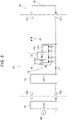
- the power supply unit 10 includes the power supply 12, a positive electrode side discharge terminal 41a and a negative electrode side discharge terminal 41b that constitute the discharge terminal 41, a positive electrode side charging terminal 43a and a negative electrode side charging terminal 43b that constitute the charging terminal 43, the controller 50 connected between a positive electrode side of the power supply 12 and the positive electrode side discharge terminal 41a and between a negative electrode side of the power supply 12 and the negative electrode side discharge terminal 41b, the charger 13 disposed on a power transmission path between the charging terminal 43 and the power supply 12, the voltage sensor 16 connected in parallel with the power supply 12, a switch 19 disposed on a power transmission path between the power supply 12 and the discharge terminal 41, and plural electrostatic capacitance sensors 80 connected to the controller 50.
- the switch 19 is configured with, for example, a MOSFET, and is opened and closed by the controller 50 adjusting a gate voltage.
- the controller 50 includes an aerosol generation request detector 51, a liquid detector 52, a power controller 53, and a notification controller 54.
- the aerosol generation request detector 51 detects an aerosol generation request based on an output result of the intake sensor 15.
- the intake sensor 15 outputs a value of a pressure change in the power supply unit 10 caused by suction of the user through the suction port 32.
- the intake sensor 15 is, for example, a pressure sensor that outputs an output value (for example, a voltage value or a current value) corresponding to an atmospheric pressure that changes in accordance with a flow rate of air suctioned from the air intake port 11c toward the suction port 32 (that is, a puff operation of the user).
- the liquid detector 52 Based on an output of the electrostatic capacitance sensor 80, the liquid detector 52 detects leakage of a liquid inside the power supply unit case 11 (hereinafter, referred to as liquid leakage detection), or detects entering of the liquid into the power supply unit case 11 (hereinafter, referred to as liquid entering detection). Further, the liquid detector 52 prohibits charging/discharging of the power supply 12 in accordance with a detection result. According to such a liquid detector 52, it is possible to avoid an influence of the leakage of the liquid, the entering of the liquid, or the like on an operation of the aerosol suction device 1. Further, the electrostatic capacitance sensor 80 is used, so that the leakage of the liquid and the entering of the liquid can be accurately detected with an inexpensive configuration. A specific processing procedure of the liquid detector 52 will be described later.
- the notification controller 54 controls the notification unit 45 so as to notify various pieces of information.
- the notification controller 54 controls the notification unit 45 so as to notify a replacement timing of the second cartridge 30 in response to detection of the replacement timing of the second cartridge 30.
- the notification controller 54 notifies the replacement timing of the second cartridge 30 based on the number of puff operations or accumulated energization time for the load 21 that are stored in the memory 18.
- the notification controller 54 is not limited to the notification of the replacement timing of the second cartridge 30, and may notify a replacement timing of the first cartridge 20, a replacement timing of the power supply 12, a charging timing of the power supply 12, and the like.
- the power controller 53 controls discharge of the power supply 12 via the discharge terminal 41 by turning ON/OFF the switch 19 when the aerosol generation request detector 51 detects an aerosol generation request.
- the power controller 53 performs control such that an amount of an aerosol generated by the load 21 atomizing the aerosol source falls within a desired range, in other words, performs control such that an amount of power supplied from the power supply 12 to the load 21 falls within a certain range.
- the power controller 53 controls ON/OFF of the switch 19 by, for example, pulse width modulation (PWM) control.
- PWM pulse width modulation
- the power controller 53 may control ON/OFF of the switch 19 by pulse frequency modulation (PFM) control.
- PFM pulse frequency modulation
- the power controller 53 may stop power supply from the power supply 12 to the load 21 when a predetermined period has elapsed after the power supply to the load 21 is started. In other words, the power controller 53 stops the power supply from the power supply 12 to the load 21 when a puff period exceeds a predetermined period even within the puff period during which the user actually performs the puff operation. The predetermined period is determined in order to prevent a variation in the puff period of the user.
- the power controller 53 controls an ON/OFF duty ratio of the switch 19 in a single puff operation in accordance with a power storage amount of the power supply 12. For example, the power controller 53 controls an on-time interval (pulse interval) for supplying power from the power supply 12 to the load 21, or controls an on-time length (pulse width) for supplying power from the power supply 12 to the load 21.
- the power controller 53 detects an electrical connection between the charging terminal 43 and the external power supply 60 and controls charging of the power supply 12 via the charger 13.
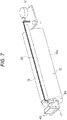
- the power supply unit 10 includes a first circuit board 71 provided with the charging terminal 43 and the like, a second circuit board 72 provided with the controller 50, the charger 13, the switch 19 and the like, and a conductive member 73 that electrically connects the first circuit board 71 to the second circuit board 72.
- the conductive member 73 of the present embodiment is configured using a flexible printed circuit board (FPCB), but may be configured with a conductive wire.
- the first circuit board 71 and the second circuit board 72 are arranged apart from each other. Specifically, the first circuit board 71 is provided on one end side in the length direction of the power supply 12 (longitudinal direction A), the second circuit board 72 is provided on the other end side in the length direction of the power supply 12 (longitudinal direction A), and the first circuit board 71 and the second circuit board 72 are electrically connected to each other via the conductive member 73 that extends in the length direction of the power supply 12 along a peripheral surface of the power supply 12.
- an electrolytic solution of the power supply 12 is assumed as a liquid leaked inside the power supply unit case 11. It should be noted that in the following description, the term "electrolytic solution” may indicate either an ionic liquid or a flame retardant organic solvent.
- the power supply 12 may include an electrolyte other than an electrolytic solution.
- the power supply 12 may include both a solid or gel-shaped solid electrolyte and an electrolytic solution.
- the electrolytic solution may be a mixed solution containing a plurality of liquids.
- a lithium salt or the like for improving performance of the power supply 12 may be added as an additive to the electrolytic solution.
- the electrostatic capacitance sensor 80 is a sensor that detects an object, a fluid, or the like based on a change in an electrostatic capacitance that occurs between a sensor electrode 81 and a GND potential, and detects the electrolytic solution leaked from the power supply 12 in the present embodiment.
- the electrostatic capacitance sensor 80 of the present embodiment constitutes, between the electrode 81 and the GND potential, a pseudo capacitor by sandwiching a first porous body 82 that absorbs the electrolytic solution so as to guide the electrolytic solution to the electrode 81, and measures an electrostatic capacitance of the capacitor by the controller 50.
- the controller 50 charges and discharges the capacitor including the electrostatic capacitance sensor 80, and measures an electrostatic capacitance based on a time required for the charging and discharging.
- an electrostatic capacitance sensor 80 when the first porous body 82 absorbs the electrolytic solution, an electrostatic capacitance is changed. Therefore, the controller 50 can accurately detect the electrolytic solution leaked from the power supply 12.
- the electrode 81 can be configured with a metal plate and the first porous body 82 can be configured with a cotton sheet, a sponge, absorbent cotton, or the like, the electrolytic solution leakage of the power supply 12 can be detected with an inexpensive configuration.
- the electrode 81 and the first porous body 82 may be unitized so as to form an electrostatic capacitance sensor unit.
- the electrostatic capacitance sensor 80 may be configured with a capacitor including two facing electrodes 81.
- the electrostatic capacitance sensor 80 is disposed in the power supply 12 at a location where the electrolytic solution leaks easily.
- the electrolytic solution leakage easily occurs in the vicinity of the tab 12b and the safety valve. Therefore, it is desirable that at least a part of the first porous body 82 is disposed so as to abut against the tab 12b and the safety valve or is disposed in the vicinity of the tab 12b and the safety valve. Accordingly, when the electrolytic solution leakage occurs in the vicinity of the tab 12b and the safety valve of the power supply 12, the electrolytic solution leakage can be effectively and rapidly detected.
- At least a part of the first porous body 82 being disposed so as to abut against the tab 12b and the safety valve obviously means that the entire first porous body 82 abuts against the tab 12b and the safety valve, and means that a part of the first porous body 82 (for example, arm portion) extends toward the tab 12b and the safety valve and abuts against the tab 12b and the safety valve while the first porous body 82 is separated from the tab 12b and the safety valve.
- the vicinity is a position including at least a position that can be in contact with an electrolytic solution when the electrolytic solution leaks.
- the power supply unit 10 including a power supply holder (not shown) that is disposed inside the power supply unit case 11 and holds the power supply 12, it is desirable that at least a part of the first porous body 82 is disposed between the power supply 12 and the power supply holder.
- the power supply holder generates an inevitable gap with the power supply 12 and the electrolytic solution easily enters the gap. Accordingly, even when the electrolytic solution leaks between the power supply 12 and the power supply holder, the electrolytic solution leakage can be detected.
- the electrostatic capacitance sensor 80 may be disposed between the power supply 12 and the power supply holder.
- the power supply holder may be electrically conductive or non-conductive.
- an electrostatic capacitance of the electrostatic capacitance sensor 80 is changed, based on the electrolytic solution absorbed by the first porous body 82, with a significant difference. Further, it is preferable that the first porous body 82 rapidly transports the absorbed electrolytic solution to a location where the electrostatic capacitance of the electrostatic capacitance sensor 80 is changed. Under such a background, physical properties such as a size of the first porous body 82 are preferably limited. As a result, the first porous body 82 may not be able to absorb the electrolytic solution depending on an amount of the leaked electrolytic solution. It should be noted that the electrolytic solution that cannot be absorbed by the first porous body 82 includes one that cannot be completely absorbed while being once in contact with the first porous body 82 and one that cannot be in contact with the first porous body 82.
- the electrostatic capacitance sensor 80 when the electrostatic capacitance sensor 80 is disposed in the vicinity of the circuit boards 71 and 72, it is desirable to provide a second porous body 84 between the electrostatic capacitance sensor 80 (electrode 81) and the circuit boards 71 and 72. Accordingly, the second porous body 84 can absorb the electrolytic solution that cannot be absorbed by the first porous body 82. As a result, the circuit boards 71 and 72 can be protected from the electrolytic solution that cannot be absorbed by the first porous body 82.
- a liquid that enters into the power supply unit case 11 is assumed to be water that enters during submersion.
- a structure of the electrostatic capacitance sensor 80 used for the liquid entering detection is substantially the same as the structure of the electrostatic capacitance sensor 80 used for the liquid leakage detection. It is preferable that the electrostatic capacitance sensor 80 used for the liquid entering detection also preferably includes both the first porous body 82 and the second porous body 84.
- the controller 50 detects, based on the output of the electrostatic capacitance sensor 80, entering of water from openings K1 to K5 provided in the power supply unit case 11. For example, it is desirable that at least a part of the first porous body 82 that guides water toward the electrode 81 of the electrostatic capacitance sensor 80 is disposed so as to abut against the openings K1 to K5 or is disposed in the vicinity of the openings K1 to K5. Accordingly, entering of water can be effectively detected when the water enters from the openings K1 to K5.
- At least a part of the first porous body 82 being disposed so as to abut against the openings K1 to K5 obviously means that the entire first porous body 82 abuts against the openings K1 to K5, and means that a part of the first porous body 82 (for example, arm portion) extends toward the openings K1 to K5 and abuts against the openings K1 to K5 while the first porous body 82 is separated from the openings K1 to K5.
- the first porous body 82 being disposed in the vicinity of the openings K1 to K5 obviously means that the entire first porous body 82 is positioned in the vicinity of the openings K1 to K5, and means that a part of the first porous body 82 (for example, arm portion) is positioned in the vicinity of the openings K1 to K5 while the first porous body 82 is separated from the openings K1 to K5.
- the vicinity is a position that can be in contact with water when the water enters.
- the electrostatic capacitance of the electrostatic capacitance sensor 80 is rapidly changed, so that the submersion can be rapidly detected.
- the electrostatic capacitance sensor 80 can be disposed apart from the openings K1 to K5, a degree of freedom in disposing an electronic component in the power supply unit case 11 is improved. As a result, the power supply unit 10 can be downsized.
- the opening K1 is formed in the power supply unit case 11 and around the charging terminal 43.
- the electrostatic capacitance sensor 80 is disposed in the vicinity of the opening K1 in the power supply unit case 11, entering of water from around the charging terminal 43 can be detected. Further, an influence of the entering of the water on the operation of the aerosol suction device 1 can be avoided.
- the opening K2 is the air intake port 11c.
- the electrostatic capacitance sensor 80 is disposed in the vicinity of the opening K2 in the power supply unit case 11, entering of water from the air intake port 11c can be detected. Further, an influence of the entering of the water on the operation of the aerosol suction device 1 can be avoided.
- the opening K3 is formed in the power supply unit case 11 and around the operation unit 14.
- the electrostatic capacitance sensor 80 is disposed in the vicinity of the opening K3 in the power supply unit case 11, entering of water from around the operation unit 14 can be detected. Further, an influence of the entering of the water on the operation of the aerosol suction device 1 can be avoided.
- the opening K4 is formed in the power supply unit case 11 and around the discharge terminal 41.
- the electrostatic capacitance sensor 80 is disposed in the vicinity of the opening K4 in the power supply unit case 11, entering of water from around the discharge terminal 41 can be detected. Further, an influence of the entering of the water on the operation of the aerosol suction device 1 can be avoided.
- the opening K5 is the air supply portion 42.
- the electrostatic capacitance sensor 80 is disposed in the vicinity of the opening K5 in the power supply unit case 11, entering of water from the air supply portion 42 can be detected. Further, an influence of the entering of the water on the operation of the aerosol suction device 1 can be avoided.
- the opening K2 and the opening K5 are positively provided in the power supply unit case 11 as air flow paths. Therefore, the opening K2 and the opening K5 themselves may become water entering paths.
- the openings K1, K3, and K4 are provided for assembling separate components to the power supply unit case 11. Therefore, to be precise, in the openings K1, K3, and K4, buffers for absorbing product tolerances of the components to be assembled to the power supply unit case 11 may become water entering paths.
- the electrostatic capacitance sensors 80 are arranged at both a location where the electrolytic solution easily leaks and a location where the water easily enters, so that both the liquid leakage detection and the liquid entering detection can be performed. Both the liquid leakage detection and the liquid entering detection are performed, so that safety of the power supply unit 10 and the aerosol suction device 1 can be improved.
- the power supply unit 10 includes a plurality of electrostatic capacitance sensors 80.
- the controller 50 liquid detector 52 diagnoses a state of the power supply unit 10 (leakage of a liquid or entering of a liquid) based on outputs of the plurality of electrostatic capacitance sensors 80. Accordingly, the state of the power supply unit 10 can be accurately diagnosed as compared with a case where the state of the power supply unit 10 is diagnosed based on an output of one electrostatic capacitance sensor 80.
- a method for detecting the leakage of the liquid or the entering of the liquid by using the plurality of electrostatic capacitance sensors 80 will be described in detail.
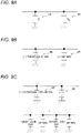
- the plurality of electrostatic capacitance sensors 80 are connected in parallel to each other. Accordingly, wiring for connecting the plurality of electrostatic capacitance sensors 80 and the controller 50 can be simplified. At the same time, the wiring for connecting the plurality of electrostatic capacitance sensors 80 and the controller 50 can be reduced. Further, when the plurality of electrostatic capacitance sensors 80 are connected in parallel, the controller 50 can diagnose the state of the power supply unit 10 based on a sum of capacitances that are output values of the plurality of electrostatic capacitance sensors 80. Therefore, even when the number of electrostatic capacitance sensors 80 is increased, a complicated signal processing for an output value thereof is unnecessary.
- a state where the capacitance of the electrostatic capacitance sensor 80 is defined by the air 100% indicates a state where the electrostatic capacitance sensor 80 does not detect any detection target liquid.
- ⁇ liquid is a relative permittivity of a detection target liquid
- ⁇ 0 is a permittivity of air
- S is an area of one parallel plate electrode
- d is a distance between plates of the parallel plate electrodes.
- ⁇ liquid is a relative permittivity of a detection target liquid
- ⁇ 0 is a permittivity of air
- S is an area of one parallel plate electrode
- d is a distance between plates of the parallel plate electrodes.
- the liquid may be locally present and may diffuse in a wide range inside the power supply unit case 11.
- an electrostatic capacitance sensor 80 is provided in the vicinity of a location where the liquid is present, the liquid leakage and the like can be accurately detected with one electrostatic capacitance sensor 80.
- the electrostatic capacitance sensor 80 when the electrostatic capacitance sensor 80 is not provided at the location where the liquid is present, a capacitance of one electrostatic capacitance sensor 80 is predominantly defined by air whose permittivity and relative permittivity are extremely small. Therefore, since the electrostatic capacitance output by one electrostatic capacitance sensor 80 has a small value, the liquid leakage and the like may not be detected by only one electrostatic capacitance sensor 80. Similarly, when the liquid diffuses in a wide range inside the power supply unit case 11, since most of the capacitance of one electrostatic capacitance sensor 80 is defined by air, the liquid leakage and the like also may not be detected by only one electrostatic capacitance sensor 80.
- a liquid at a location that cannot be obtained by only one electrostatic capacitance sensor 80 can also be detected. Further, as long as a liquid having the same amount is detected as described above, an electrostatic capacitance detected by the controller 50 is the same regardless of a ratio of a liquid detected by the plurality of capacitance sensors 80.
- the liquid leakage and the like cannot be detected by one electrostatic capacitance sensor 80, the liquid leakage and the like can be detected by other electrostatic capacitance sensors 80. Further, even when the electrolytic solution or the like diffuses in a wide range, the liquid leakage and the like can be detected by a sum of the plurality of electrostatic capacitance sensors 80. Therefore, the state of the power supply unit 10 can be accurately diagnosed.
- the electrostatic capacitance sensors 80 may be the same.
- the electrostatic capacitance sensors 80 are configured using the electrodes 81 of the same material, the same dimension, and the same part number. Further, dimensions and part numbers of the plurality of electrostatic capacitance sensors 80 are unified, so that the specifications of the plurality of electrostatic capacitance sensors 80 may be the same. Accordingly, a cost of the power supply unit 10 can be reduced by reducing a procurement cost. Further, an output value for a physical quantity is the same among the plurality of electrostatic capacitance sensors 80, and a processing for a plurality of output values can be simplified.
- the controller 50 includes a plurality of pins for inputting sensor signals and power and outputting control signals. As shown in Fig. 5 , the plurality of electrostatic capacitance sensors 80 are connected to the same pins 50a and 50b among the plurality of pins. Accordingly, since the controller 50 including a large number of pins is unnecessary, a cost and a size of the controller 50 can be reduced. Further, wiring for connecting the plurality of electrostatic capacitance sensors 80 to the controller 50 can be prevented from becoming complicated (spaghetti-like).
- Table 1 shows typical dielectrics among dielectrics that can be present inside the aerosol suction device 1 and relative permittivities thereof.
- Dielectric Relative permittivity ⁇ r Application Ethylene carbonate (EC) 90.0 Electrolytic solution Water 80.4 Aerosol source Propylene carbonate (PC) 65.0 Electrolytic solution Glycerin (G) 47.0 Aerosol source Dimethyl sulfoxide (DMSO) 46.7 Electrolytic solution Propylene glycol (PG) 32.0 Aerosol source Dimethyl carbonate (DMC) 3.1 Electrolytic solution Ethyl methyl carbonate (EMC) 2.9 Electrolytic solution Diethyl carbonate 2.8 Electrolytic solution Air 1.0 Atmospheric atmosphere
- the controller 50 diagnoses an abnormality of the power supply unit 10 based on a comparison between output values of the plurality of electrostatic capacitance sensors 80 and a threshold that is based on a smaller one of a permittivity or relative permittivity of the water and a permittivity or relative permittivity of the electrolytic solution (see Fig. 11 ). Accordingly, since the threshold is set based on one, of the water and the electrolytic solution, that has a smaller permittivity or relative permittivity, occurrence of the abnormality can be rapidly detected without making a distinction between the electrolytic solution leakage and the submersion.
- Fig. 11 it is assumed that any one of propylene carbonate (PC), dimethyl sulfoxide (DMSO), dimethyl carbonate (DMC), ethyl methyl carbonate (EMC), and diethyl carbonate or a mixed solution thereof is used as the electrolytic solution.
- PC propylene carbonate
- DMSO dimethyl sulfoxide
- DMC dimethyl carbonate
- EMC ethyl methyl carbonate
- diethyl carbonate or a mixed solution thereof is used as the electrolytic solution.
- a relative permittivity or permittivity of the mixed solution is obtained by adding relative permittivities or permittivities of the respective solutions that constitute the mixed solution in accordance with ratios thereof. Therefore, 2.8 to 65.0 is shown as a relative permittivity that can be obtained by the electrolytic solution.
- 80.4 is a relative permittivity that can be obtained by water at room temperature, and less than 2.8 is shown as a relative permittivity in the absence of a liquid such as an electrolytic solution or water.
- the present disclosure is not limited thereto.
- An obtainable value of the relative permittivity can be set in accordance with components of the electrolytic solution and the like.
- the threshold is set based on the electrolytic solution having a smaller relative permittivity between the water and the electrolytic solution.
- a relative permittivity that can be obtained by the electrolytic solution may be obtained experimentally, or may be obtained by adding known relative permittivities of the liquids that constitute the mixed solution in accordance with a composition ratio thereof.
- a permittivity may be used instead of a relative permittivity.
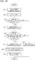
- the controller 50 when executing control example 2, the controller 50 first charges the capacitor (pseudo capacitor or capacitor configured by the electrostatic capacitance sensor 80) with a current generated inside the controller 50 (S201) and activates a timer (S202). Thereafter, the controller 50 repeatedly determines completion of charging of the capacitor (S203), releases electric charge accumulated in the capacitor when a determination result is YES, and obtains the time T required for charging or charging/discharging of the capacitor (S204).
- the controller 50 determines whether the time T is larger than the second threshold (S205). When a determination result is NO, the controller 50 determines that the electrostatic capacitance is small (S206), that is, determines that the electrolytic solution leakage and the submersion do not occur, and then ends the single detection processing. On the other hand, when YES is determined in step S205, the controller 50 determines that the electrostatic capacitance is moderate (S207), that is, determines that the electrolytic solution leakage or the submersion has been detected (S208), and prohibits a discharging processing from the power supply 12 to at least the load 21 and a charging processing of the power supply 12 (S209).
- the notification controller 54 may control the notification unit 45 so as to notify at the same time as step S209 or before and after step S209 that the electrolytic solution leakage has been detected. Further, the controller 50 may perform control so as to prohibit all charging and discharging processes with respect to the power supply 12 in step S209. Further, the controller 50 may perform control so as to prohibit a discharging processing from the power supply 12 to components other than the controller 50 in step S209.
- the threshold may be set based on the electrolytic solution having a smaller relative permittivity between the water and the electrolytic solution.
- electrostatic capacitances of the electrostatic capacitance sensors 80 during the electrolytic solution leakage or the submersion are derived based on Formula (I) and Formula (II). From the derived electrostatic capacitances, a time required for charging or charging/discharging the capacitors during the electrolytic solution leakage or the submersion may be derived, and a derived value may be used as the threshold.
- times required for charging or charging/discharging the capacitors during the electrolytic solution leakage and the submersion may be respectively and experimentally calculated, and a smaller value may be used as the threshold. It is apparent that the threshold set as described above is based on a smaller one of the relative permittivity or permittivity of the water and the relative permittivity or permittivity of the electrolytic solution.
- step S205 the time T is compared with the first threshold having a dimension of time.
- the time T may be converted into a permittivity, and a converted value may be compared with a first threshold having a dimension of permittivity.
- the time T may be converted into a relative permittivity, and a converted value may be compared with a first threshold corresponding to the relative permittivity.
- the present disclosure is not limited to the above-described embodiment, and can be appropriately modified, improved, and the like.
- the electrolytic solution leakage and the submersion are detected without distinction by using the plurality of electrostatic capacitance sensors 80, either one of the electrolytic solution leakage and the submersion may be detected using the plurality of electrostatic capacitance sensors 80.
- the controller 50 can diagnose the leakage of the electrolytic solution based on a comparison between output values of the plurality of electrostatic capacitance sensors 80 and a threshold that is based on a permittivity or a relative permittivity of the electrolytic solution.
- the controller 50 can diagnose entering of the water from the openings K1 to K5 based on a comparison between the output values of the plurality of electrostatic capacitance sensors 80 and a threshold that is based on a permittivity or a relative permittivity of the water.
- the plurality of sensors are not limited to the electrostatic capacitance sensors 80 as long as the plurality of sensors are sensors that can output the same physical quantity inside the power supply unit case 11.
- the plurality of sensors may be sensors that can detect a bulge of the power supply 12.
- the controller 50 may be configured to diagnose the bulge of the power supply 12 based on outputs of the plurality of sensors. Accordingly, the abnormal bulge of the power supply 12 can be rapidly detected.
- a sensor that can detect the bulge of the power supply 12 a pressure sensor, a strain gauge, or the like may be used.
Description
- The present disclosure relates to an aerosol suction device having a power supply unit.
- Japanese Translation of
PCT International Application Publication No. JP-T-2016-536023 - Description of
Chinese Patent Publication No. 103099319 (hereinafter, referred to as Patent Literature 2) discloses a sealing layer that prevents outflow of an electrolytic solution and an adsorption layer that adsorbs the electrolytic solution when the outflow of the electrolytic solution cannot be stopped by the sealing layer. - Description of
Chinese Patent Publication No. 107432498 (hereinafter, referred to as Patent Literature 3) discloses an electronic cigarette in which a housing made of aluminum and a plastic film is provided in a housing made of steel in order to prevent an electrolytic solution from flowing out to outside. - However, in
Patent Literatures 1 to 3, although a method is disclosed which prevents other components from being influenced when the electrolytic solution leaks from the battery, the leakage of the electrolytic solution from the battery cannot be recognized. In other words, even after the electrolytic solution leaks, an operation of the personal electronic inhaler or the like is continued. - Further, in
Patent Literatures 1 to 3, when a liquid enters into the housing due to submersion or the like, the entering of the liquid cannot be recognized. In a power supply unit of an aerosol generation apparatus, it is important to recognize a state that may influence an operation of the aerosol generation apparatus, such as the leakage of the liquid, the entering of the liquid, a bulge of the power supply (cell), and the like. - An object of the present disclosure is to provide an aerosol suction device comprising a power supply unit that can accurately diagnose a state of the power supply unit.
EP 3 476 645 A1 discloses a vehicle battery safety sensor system. It proposes to mount batteries into an enclosure (so-called "battery cell bay 26") that comprises a "low point area 32" where any liquid could accumulate in a case of spillage. It is in this area, where the corresponding teaching proposes to provide a "first sensor 36". -
JP H10-012284 A -
EP 3 072 406 A1 discloses an electronic cigarette and specifically proposes a capacitive sensor for sensing a pressure differential. The teaching claims that capacitive pressure sensors are more precise and sensitive than mechanical sensors. -
US 2004/108861 A1 was acknowledged to merely disclose the detection of water by using capacitive sensors as, for example, in a wristwatch. - The present invention provides the subject-matter of the independent claim. Further preferred embodiments are defined in the dependent claims.
- According to the present disclosure, the influence of at least one of the leakage of the liquid and the entering of the liquid can be avoided.
-
-
Fig. 1 is a perspective view of an aerosol suction device on which a power supply unit according to an embodiment of the present disclosure is mounted; -
Fig. 2 is another perspective view of the aerosol suction device ofFig. 1 ; -
Fig. 3 is a cross-sectional view of the aerosol suction device ofFig. 1 ; -
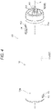
Fig. 4 is a perspective view of the power supply unit in the aerosol suction device ofFig. 1 ; -
Fig. 5 is a schematic diagram showing a circuit configuration of the power supply unit in the aerosol suction device ofFig. 1 ; -
Fig. 6 is a block diagram showing a configuration of main parts of the power supply unit in the aerosol suction device ofFig. 1 ; -
Fig. 7 is a perspective view of main parts showing a board configuration of the power supply unit in the aerosol suction device ofFig. 1 ; -
Fig. 8 is an illustrative diagram illustrating an electrostatic capacitance sensor of the power supply unit in the aerosol suction device ofFig. 1 ; -
Fig. 9A is an illustrative diagram of a combined capacitance of two electrostatic capacitance sensors connected in parallel, and is an illustrative diagram showing a state where none of the electrostatic capacitance sensors detects a liquid; -
Fig. 9B is an illustrative diagram of a combined capacitance of the two electrostatic capacitance sensors connected in parallel, and is an illustrative diagram showing a state where one of the electrostatic capacitance sensors detects the liquid; -
Fig. 9C is an illustrative diagram of a combined capacitance of the two electrostatic capacitance sensors connected in parallel, and is an illustrative diagram showing a state where the two electrostatic capacitance sensors detect the liquid; -
Fig. 10 is a flowchart showing a control example of the power supply unit in the aerosol suction device ofFig. 1 ; and -
Fig. 11 is an illustrative diagram of a threshold used in the control example ofFig. 10 . - Hereinafter, the power supply unit of the aerosol generation apparatus according to an embodiment of the present disclosure will be described. First, the aerosol suction device on which the power supply unit is mounted will be described with reference to
Figs. 1 to 6 . - An
aerosol suction device 1 is a device for suctioning a flavor without combustion and has a rod shape that extends along a predetermined direction (hereinafter, referred to as a longitudinal direction A). As shown inFigs. 1 and2 , theaerosol suction device 1 is provided with apower supply unit 10, afirst cartridge 20, and asecond cartridge 30 in this order along the longitudinal direction A. Thefirst cartridge 20 is attachable to and detachable from thepower supply unit 10, and thesecond cartridge 30 is attachable to and detachable from thefirst cartridge 20. In other words, thefirst cartridge 20 and thesecond cartridge 30 can be replaced with each other. - As shown in
Figs. 3 to 6 , thepower supply unit 10 of the present embodiment houses apower supply 12, acharger 13, acontroller 50, various sensors, and the like inside a cylindrical powersupply unit case 11. - The
power supply 12 is a rechargeable secondary battery, and preferably a lithium-ion secondary battery. Thepower supply 12 of the present embodiment includes acylindrical case 12a that houses various components such as an electrode and an electrolytic solution (not shown). A pair oftabs 12b (seeFig. 8 ) serving as positive and negative electrodes are provided at one end portion or both end portions of thepower supply 12 in a length direction (longitudinal direction A). In other words, thepositive electrode tab 12b may be provided on one end of both ends of thepower supply 12 in the length direction, and thepositive electrode tab 12b may be provided on the other end of both ends of thepower supply 12 in the length direction. Alternatively, both thepositive electrode tab 12b and thenegative electrode tab 12b may be provided on one end of thepower supply 12 in the length direction. Further, thepower supply 12 includes a safety valve (not shown) that opens when an internal pressure of thepower supply 12 is larger than a predetermined pressure, on one end portion or both end portions in the length direction. - A
discharge terminal 41 is provided on atop portion 11a positioned on one end side (first cartridge 20 side) of the powersupply unit case 11 in the longitudinal direction A. Thedischarge terminal 41 protrudes from an upper surface of thetop portion 11a toward thefirst cartridge 20 and can be electrically connected to aload 21 of thefirst cartridge 20. - An
air supply portion 42 that supplies air to theload 21 of thefirst cartridge 20 is provided in the vicinity of thedischarge terminal 41 on the upper surface of thetop portion 11a. - A
charging terminal 43 that can be electrically connected to an external power supply 60 (seeFig. 5 ) that can charge thepower supply 12 is provided inside abottom portion 11b positioned on the other end side (side opposite to the first cartridge 20) of the powersupply unit case 11 in the longitudinal direction A. Thecharging terminal 43 is provided inside a side surface of thebottom portion 11b, and at least one of a USB terminal, a microUSB terminal, and a Lightning (registered trademark) terminal can be connected to thecharging terminal 43. - The
charging terminal 43 may be a power receiving unit that can receive, in a wireless manner, power supplied from theexternal power supply 60. In such a case, the charging terminal 43 (power receiving unit) may be configured with a power receiving coil. A method for the wireless power transfer may be electromagnetic induction or magnetic resonance. Further, the chargingterminal 43 may be a power receiving unit that can receive, without contact, the power supplied from theexternal power supply 60. As another example, at least one of the USB terminal, the microUSB terminal, and the Lightning (registered trademark) terminal can be connected to the chargingterminal 43, and the chargingterminal 43 may include the above-described power receiving unit. - That is, in the
power supply unit 10, thedischarge terminal 41 and the chargingterminal 43 are separately configured and arranged apart from each other in the longitudinal direction A. Therefore, thepower supply unit 10 is configured such that theexternal power supply 60 can be electrically connected to the chargingterminal 43 in a state where thepower supply 12 can be discharged via thedischarge terminal 41. Further, in thepower supply unit 10, when an aerosol generation request is detected while the chargingterminal 43 and theexternal power supply 60 are electrically connected, simultaneous charging and discharging of thepower supply 12 is prohibited. - The power
supply unit case 11 is provided with anoperation unit 14 that can be operated by a user, on a side surface of thetop portion 11a, so as to face a side opposite to the chargingterminal 43. More specifically, theoperation unit 14 and the chargingterminal 43 are in a point-symmetrical relationship with an intersection of a straight line that connects theoperation unit 14 to the chargingterminal 43 and a center line L of thepower supply unit 10 in the longitudinal direction A. Theoperation unit 14 is configured with a button type switch, a touch panel, and the like and is used when a use intention of the user is reflected so as to activate/interrupt thecontroller 50 and various sensors. Thecontroller 50 and anintake sensor 15 that detects a puff operation are provided in the vicinity of theoperation unit 14. - The
charger 13 controls charging power input from the chargingterminal 43 to thepower supply 12. Thecharger 13 is configured by using a charging IC that is mounted on a charging cable connected to the chargingterminal 43 and that includes a converter that converts a direct current from aninverter 61 or the like into a direct current having different magnitude, a voltmeter, an ammeter, a processor, and the like. Theinverter 61 or the like converts an alternating current into a direct current. - As shown in
Fig. 6 , thecontroller 50 is connected to thecharger 13, theoperation unit 14, various sensor devices such as theintake sensor 15 that detects the puff (intake) operation, avoltage sensor 16 that measures a voltage of thepower supply 12, atemperature sensor 17 that detects a temperature, anelectrostatic capacitance sensor 80 that is separate from theintake sensor 15 and detects electrostatic capacitance inside the powersupply unit case 11, and amemory 18 that stores the number of puff operations, time for energizing theload 21, or the like, and performs various controls of theaerosol suction device 1. Theintake sensor 15 may be configured with a condenser microphone, a pressure sensor, or the like. Specifically, thecontroller 50 is a processor (MCU: Micro Controller Unit). More specifically, the structure of the processor is an electric circuit in which circuit elements such as semiconductor elements are combined. Details of thecontroller 50 will be described later. - The power
supply unit case 11 is provided with anair intake port 11c that takes outside air into inside thereof. Theair intake port 11c may be provided around theoperation unit 14 or may be provided around the chargingterminal 43. - As shown in
Fig. 3 , thefirst cartridge 20 includes, inside acylindrical cartridge case 27, areservoir 23 that stores anaerosol source 22, theelectrical load 21 that atomizes theaerosol source 22, awick 24 that draws the aerosol source from thereservoir 23 into theload 21, anaerosol flow path 25 that causes an aerosol generated by the atomization of theaerosol source 22 to flow toward thesecond cartridge 30, and anend cap 26 that houses a part of thesecond cartridge 30. - The
reservoir 23 is partitioned and formed so as to surround a periphery of theaerosol flow path 25 and stores theaerosol source 22. A porous body such as a resin web or cotton may be housed in thereservoir 23, and theaerosol source 22 may be impregnated in the porous body. In thereservoir 23, the porous body on the resin web or the cotton may not be housed and only theaerosol source 22 may be stored. Theaerosol source 22 contains liquids such as glycerin, propylene glycol, and water. - The
wick 24 is a liquid holding member that draws theaerosol source 22 from thereservoir 23 into theload 21 by using a capillary phenomenon, and is configured with, for example, glass fiber or porous ceramic. - The
load 21 atomizes theaerosol source 22 without combustion by power supplied from thepower supply 12 via thedischarge terminal 41. Theload 21 is configured with an electric heating wire (coil) wound at a predetermined pitch. Theload 21 may be an element that can atomize theaerosol source 22 so as to generate an aerosol, and is, for example, a heating element or an ultrasonic generator. Examples of the heating element include a heating resistor, a ceramic heater, and an induction heating heater. - The
aerosol flow path 25 is downstream of theload 21 and provided on the center line L of thepower supply unit 10. - The
end cap 26 includes acartridge housing portion 26a that houses a part of thesecond cartridge 30, and acommunication path 26b that communicates theaerosol flow path 25 with thecartridge housing portion 26a. - The
second cartridge 30 stores aflavor source 31. Thesecond cartridge 30 is detachably housed in thecartridge housing portion 26a provided in theend cap 26 of thefirst cartridge 20. An end portion of thesecond cartridge 30 on a side opposite to afirst cartridge 20 side is asuction port 32 of the user. Thesuction port 32 is not limited to the case of being integrally formed with thesecond cartridge 30 and may be configured to be attachable to and detachable from thesecond cartridge 30. Accordingly, thesuction port 32 is separate from thepower supply unit 10 and thefirst cartridge 20, so that thesuction port 32 can be kept hygienic. - The
second cartridge 30 causes an aerosol generated by atomizing theaerosol source 22 by theload 21 to pass through theflavor source 31, so that a flavor is given to the aerosol. As a raw material piece that constitutes theflavor source 31, a molded body obtained by molding shredded tobacco or a tobacco raw material into a granular shape can be used. Theflavor source 31 may be configured with a plant other than tobacco (for example, mint, Chinese herbs, herbs, or the like). A flavor material such as menthol may be given to theflavor source 31. - In the
aerosol suction device 1 of the present embodiment, theaerosol source 22, theflavor source 31, and theload 21 can generate an aerosol to which a flavor is added. That is, theaerosol source 22 and theflavor source 31 can be referred to as an aerosol generation source that generates an aerosol. - In addition to the configuration in which the
aerosol source 22 and theflavor source 31 are separated from each other, the configuration of the aerosol generation source used in theaerosol suction device 1 may be a configuration in which theaerosol source 22 and theflavor source 31 are integrally formed, a configuration in which theflavor source 31 is omitted and a substance that may be contained in theflavor source 31 is added to theaerosol source 22, a configuration in which a medication or the like is added to theaerosol source 22 instead of theflavor source 31, or the like. - In the
aerosol suction device 1 configured as described above, as indicated by an arrow B inFig. 3 , air that flows in from theair intake port 11c provided in the powersupply unit case 11 passes near theload 21 of thefirst cartridge 20 from theair supply portion 42. Theload 21 atomizes theaerosol source 22 drawn or moved from thereservoir 23 by thewick 24. An aerosol generated by the atomization flows through theaerosol flow path 25 together with air that flows in from theair intake port 11c, and is supplied to thesecond cartridge 30 via thecommunication path 26b. The aerosol supplied to thesecond cartridge 30 is given a flavor by passing through theflavor source 31 and is supplied to thesuction port 32. - The
aerosol suction device 1 is provided with anotification unit 45 that notifies various pieces of information. Thenotification unit 45 may be configured with a light-emitting element, may be configured with a vibration element, or may be configured with a sound output element. Further, thenotification unit 45 may be a combination of two or more elements among the light-emitting element, the vibration element, and the sound output element. Thenotification unit 45 may be provided in any of thepower supply unit 10, thefirst cartridge 20, and thesecond cartridge 30, and is preferably provided in thepower supply unit 10 in order to shorten a conductive wire from thepower supply 12. For example, a periphery of theoperation unit 14 is translucent. Thenotification unit 45 emits light by a light-emitting element such as an LED. - Next, an electric circuit of the
power supply unit 10 will be described with reference toFig. 5 . - The
power supply unit 10 includes thepower supply 12, a positive electrodeside discharge terminal 41a and a negative electrodeside discharge terminal 41b that constitute thedischarge terminal 41, a positive electrode side charging terminal 43a and a negative electrode side charging terminal 43b that constitute the chargingterminal 43, thecontroller 50 connected between a positive electrode side of thepower supply 12 and the positive electrodeside discharge terminal 41a and between a negative electrode side of thepower supply 12 and the negative electrodeside discharge terminal 41b, thecharger 13 disposed on a power transmission path between the chargingterminal 43 and thepower supply 12, thevoltage sensor 16 connected in parallel with thepower supply 12, aswitch 19 disposed on a power transmission path between thepower supply 12 and thedischarge terminal 41, and pluralelectrostatic capacitance sensors 80 connected to thecontroller 50. Theswitch 19 is configured with, for example, a MOSFET, and is opened and closed by thecontroller 50 adjusting a gate voltage. - As shown in
Fig. 6 , thecontroller 50 includes an aerosolgeneration request detector 51, aliquid detector 52, apower controller 53, and anotification controller 54. - The aerosol
generation request detector 51 detects an aerosol generation request based on an output result of theintake sensor 15. Theintake sensor 15 outputs a value of a pressure change in thepower supply unit 10 caused by suction of the user through thesuction port 32. Theintake sensor 15 is, for example, a pressure sensor that outputs an output value (for example, a voltage value or a current value) corresponding to an atmospheric pressure that changes in accordance with a flow rate of air suctioned from theair intake port 11c toward the suction port 32 (that is, a puff operation of the user). - Based on an output of the
electrostatic capacitance sensor 80, theliquid detector 52 detects leakage of a liquid inside the power supply unit case 11 (hereinafter, referred to as liquid leakage detection), or detects entering of the liquid into the power supply unit case 11 (hereinafter, referred to as liquid entering detection). Further, theliquid detector 52 prohibits charging/discharging of thepower supply 12 in accordance with a detection result. According to such aliquid detector 52, it is possible to avoid an influence of the leakage of the liquid, the entering of the liquid, or the like on an operation of theaerosol suction device 1. Further, theelectrostatic capacitance sensor 80 is used, so that the leakage of the liquid and the entering of the liquid can be accurately detected with an inexpensive configuration. A specific processing procedure of theliquid detector 52 will be described later. - The
notification controller 54 controls thenotification unit 45 so as to notify various pieces of information. For example, thenotification controller 54 controls thenotification unit 45 so as to notify a replacement timing of thesecond cartridge 30 in response to detection of the replacement timing of thesecond cartridge 30. Thenotification controller 54 notifies the replacement timing of thesecond cartridge 30 based on the number of puff operations or accumulated energization time for theload 21 that are stored in thememory 18. Thenotification controller 54 is not limited to the notification of the replacement timing of thesecond cartridge 30, and may notify a replacement timing of thefirst cartridge 20, a replacement timing of thepower supply 12, a charging timing of thepower supply 12, and the like. - The
power controller 53 controls discharge of thepower supply 12 via thedischarge terminal 41 by turning ON/OFF theswitch 19 when the aerosolgeneration request detector 51 detects an aerosol generation request. - The
power controller 53 performs control such that an amount of an aerosol generated by theload 21 atomizing the aerosol source falls within a desired range, in other words, performs control such that an amount of power supplied from thepower supply 12 to theload 21 falls within a certain range. Specifically, thepower controller 53 controls ON/OFF of theswitch 19 by, for example, pulse width modulation (PWM) control. Instead, thepower controller 53 may control ON/OFF of theswitch 19 by pulse frequency modulation (PFM) control. - The
power controller 53 may stop power supply from thepower supply 12 to theload 21 when a predetermined period has elapsed after the power supply to theload 21 is started. In other words, thepower controller 53 stops the power supply from thepower supply 12 to theload 21 when a puff period exceeds a predetermined period even within the puff period during which the user actually performs the puff operation. The predetermined period is determined in order to prevent a variation in the puff period of the user. Thepower controller 53 controls an ON/OFF duty ratio of theswitch 19 in a single puff operation in accordance with a power storage amount of thepower supply 12. For example, thepower controller 53 controls an on-time interval (pulse interval) for supplying power from thepower supply 12 to theload 21, or controls an on-time length (pulse width) for supplying power from thepower supply 12 to theload 21. - The
power controller 53 detects an electrical connection between the chargingterminal 43 and theexternal power supply 60 and controls charging of thepower supply 12 via thecharger 13. - As shown in
Fig. 7 , thepower supply unit 10 includes afirst circuit board 71 provided with the chargingterminal 43 and the like, asecond circuit board 72 provided with thecontroller 50, thecharger 13, theswitch 19 and the like, and aconductive member 73 that electrically connects thefirst circuit board 71 to thesecond circuit board 72. Theconductive member 73 of the present embodiment is configured using a flexible printed circuit board (FPCB), but may be configured with a conductive wire. - The
first circuit board 71 and thesecond circuit board 72 are arranged apart from each other. Specifically, thefirst circuit board 71 is provided on one end side in the length direction of the power supply 12 (longitudinal direction A), thesecond circuit board 72 is provided on the other end side in the length direction of the power supply 12 (longitudinal direction A), and thefirst circuit board 71 and thesecond circuit board 72 are electrically connected to each other via theconductive member 73 that extends in the length direction of thepower supply 12 along a peripheral surface of thepower supply 12. - Next, the liquid leakage detection by the controller 50 (liquid detector 52) will be described with reference to
Figs. 7 and8 . In the present embodiment, an electrolytic solution of thepower supply 12 is assumed as a liquid leaked inside the powersupply unit case 11. It should be noted that in the following description, the term "electrolytic solution" may indicate either an ionic liquid or a flame retardant organic solvent. - The
power supply 12 may include an electrolyte other than an electrolytic solution. As an example, thepower supply 12 may include both a solid or gel-shaped solid electrolyte and an electrolytic solution. Further, the electrolytic solution may be a mixed solution containing a plurality of liquids. Further, a lithium salt or the like for improving performance of thepower supply 12 may be added as an additive to the electrolytic solution. - The
electrostatic capacitance sensor 80 is a sensor that detects an object, a fluid, or the like based on a change in an electrostatic capacitance that occurs between asensor electrode 81 and a GND potential, and detects the electrolytic solution leaked from thepower supply 12 in the present embodiment. Theelectrostatic capacitance sensor 80 of the present embodiment constitutes, between theelectrode 81 and the GND potential, a pseudo capacitor by sandwiching a firstporous body 82 that absorbs the electrolytic solution so as to guide the electrolytic solution to theelectrode 81, and measures an electrostatic capacitance of the capacitor by thecontroller 50. For example, thecontroller 50 charges and discharges the capacitor including theelectrostatic capacitance sensor 80, and measures an electrostatic capacitance based on a time required for the charging and discharging. According to such anelectrostatic capacitance sensor 80, when the firstporous body 82 absorbs the electrolytic solution, an electrostatic capacitance is changed. Therefore, thecontroller 50 can accurately detect the electrolytic solution leaked from thepower supply 12. Further, since theelectrode 81 can be configured with a metal plate and the firstporous body 82 can be configured with a cotton sheet, a sponge, absorbent cotton, or the like, the electrolytic solution leakage of thepower supply 12 can be detected with an inexpensive configuration. Theelectrode 81 and the firstporous body 82 may be unitized so as to form an electrostatic capacitance sensor unit. Instead of the pseudo capacitor including only oneelectrode 81, theelectrostatic capacitance sensor 80 may be configured with a capacitor including two facingelectrodes 81. - It is desirable that the
electrostatic capacitance sensor 80 is disposed in thepower supply 12 at a location where the electrolytic solution leaks easily. Generally, in thepower supply 12, the electrolytic solution leakage easily occurs in the vicinity of thetab 12b and the safety valve. Therefore, it is desirable that at least a part of the firstporous body 82 is disposed so as to abut against thetab 12b and the safety valve or is disposed in the vicinity of thetab 12b and the safety valve. Accordingly, when the electrolytic solution leakage occurs in the vicinity of thetab 12b and the safety valve of thepower supply 12, the electrolytic solution leakage can be effectively and rapidly detected. At least a part of the firstporous body 82 being disposed so as to abut against thetab 12b and the safety valve obviously means that the entire firstporous body 82 abuts against thetab 12b and the safety valve, and means that a part of the first porous body 82 (for example, arm portion) extends toward thetab 12b and the safety valve and abuts against thetab 12b and the safety valve while the firstporous body 82 is separated from thetab 12b and the safety valve. Further, at least a part of the firstporous body 82 being disposed in the vicinity of thetab 12b and the safety valve obviously means that the entire firstporous body 82 is positioned in the vicinity of thetab 12b and the safety valve, and means that a part of the first porous body 82 (for example, arm portion) is positioned in the vicinity of thetab 12b and the safety valve while the firstporous body 82 is separated from thetab 12b and the safety valve. The vicinity is a position including at least a position that can be in contact with an electrolytic solution when the electrolytic solution leaks. - As shown in
Fig. 7 , when theelectrostatic capacitance sensor 80 is disposed on one end side of thepower supply 12 and the controller 50 (second circuit board 72) is disposed on the other end side of thepower supply 12, it is desirable to incorporate theconductive wire 83 that connects theelectrostatic capacitance sensor 80 to thecontroller 50 into theconductive member 73 that is a flexible printed circuit board. Accordingly, wiring of thepower supply unit 10 can be saved. - In a case of the
power supply unit 10 including a power supply holder (not shown) that is disposed inside the powersupply unit case 11 and holds thepower supply 12, it is desirable that at least a part of the firstporous body 82 is disposed between thepower supply 12 and the power supply holder. As a result of intensive studies by the inventors of the present application, it has been found that the power supply holder generates an inevitable gap with thepower supply 12 and the electrolytic solution easily enters the gap. Accordingly, even when the electrolytic solution leaks between thepower supply 12 and the power supply holder, the electrolytic solution leakage can be detected. In addition to the firstporous body 82, theelectrostatic capacitance sensor 80 may be disposed between thepower supply 12 and the power supply holder. The power supply holder may be electrically conductive or non-conductive. - It is preferable that an electrostatic capacitance of the
electrostatic capacitance sensor 80 is changed, based on the electrolytic solution absorbed by the firstporous body 82, with a significant difference. Further, it is preferable that the firstporous body 82 rapidly transports the absorbed electrolytic solution to a location where the electrostatic capacitance of theelectrostatic capacitance sensor 80 is changed. Under such a background, physical properties such as a size of the firstporous body 82 are preferably limited. As a result, the firstporous body 82 may not be able to absorb the electrolytic solution depending on an amount of the leaked electrolytic solution. It should be noted that the electrolytic solution that cannot be absorbed by the firstporous body 82 includes one that cannot be completely absorbed while being once in contact with the firstporous body 82 and one that cannot be in contact with the firstporous body 82. - Therefore, as shown in
Figs. 7 and8 , when theelectrostatic capacitance sensor 80 is disposed in the vicinity of thecircuit boards porous body 84 between the electrostatic capacitance sensor 80 (electrode 81) and thecircuit boards porous body 84 can absorb the electrolytic solution that cannot be absorbed by the firstporous body 82. As a result, thecircuit boards porous body 82. - Next, the liquid entering detection by the controller 50 (liquid detector 52) will be described. In the present embodiment, a liquid that enters into the power
supply unit case 11 is assumed to be water that enters during submersion. A structure of theelectrostatic capacitance sensor 80 used for the liquid entering detection is substantially the same as the structure of theelectrostatic capacitance sensor 80 used for the liquid leakage detection. It is preferable that theelectrostatic capacitance sensor 80 used for the liquid entering detection also preferably includes both the firstporous body 82 and the secondporous body 84. - The
controller 50 detects, based on the output of theelectrostatic capacitance sensor 80, entering of water from openings K1 to K5 provided in the powersupply unit case 11. For example, it is desirable that at least a part of the firstporous body 82 that guides water toward theelectrode 81 of theelectrostatic capacitance sensor 80 is disposed so as to abut against the openings K1 to K5 or is disposed in the vicinity of the openings K1 to K5. Accordingly, entering of water can be effectively detected when the water enters from the openings K1 to K5. At least a part of the firstporous body 82 being disposed so as to abut against the openings K1 to K5 obviously means that the entire firstporous body 82 abuts against the openings K1 to K5, and means that a part of the first porous body 82 (for example, arm portion) extends toward the openings K1 to K5 and abuts against the openings K1 to K5 while the firstporous body 82 is separated from the openings K1 to K5. Further, at least a part of the firstporous body 82 being disposed in the vicinity of the openings K1 to K5 obviously means that the entire firstporous body 82 is positioned in the vicinity of the openings K1 to K5, and means that a part of the first porous body 82 (for example, arm portion) is positioned in the vicinity of the openings K1 to K5 while the firstporous body 82 is separated from the openings K1 to K5. The vicinity is a position that can be in contact with water when the water enters. - In a case where the entire first
porous body 82 is disposed so as to abut against the openings K1 to K5 or is disposed in the vicinity of the openings K1 to K5, when submersion occurs, the electrostatic capacitance of theelectrostatic capacitance sensor 80 is rapidly changed, so that the submersion can be rapidly detected. When a part of the firstporous body 82 extends toward the openings K1 to K5 and abuts against the openings K1 to K5 while the firstporous body 82 is separated from the openings K1 to K5, or a part of the firstporous body 82 is positioned in the vicinity of the openings K1 to K5, since theelectrostatic capacitance sensor 80 can be disposed apart from the openings K1 to K5, a degree of freedom in disposing an electronic component in the powersupply unit case 11 is improved. As a result, thepower supply unit 10 can be downsized. - As shown in
Fig. 4 , the opening K1 is formed in the powersupply unit case 11 and around the chargingterminal 43. When theelectrostatic capacitance sensor 80 is disposed in the vicinity of the opening K1 in the powersupply unit case 11, entering of water from around the chargingterminal 43 can be detected. Further, an influence of the entering of the water on the operation of theaerosol suction device 1 can be avoided. - The opening K2 is the
air intake port 11c. When theelectrostatic capacitance sensor 80 is disposed in the vicinity of the opening K2 in the powersupply unit case 11, entering of water from theair intake port 11c can be detected. Further, an influence of the entering of the water on the operation of theaerosol suction device 1 can be avoided. - The opening K3 is formed in the power
supply unit case 11 and around theoperation unit 14. When theelectrostatic capacitance sensor 80 is disposed in the vicinity of the opening K3 in the powersupply unit case 11, entering of water from around theoperation unit 14 can be detected. Further, an influence of the entering of the water on the operation of theaerosol suction device 1 can be avoided. - The opening K4 is formed in the power
supply unit case 11 and around thedischarge terminal 41. When theelectrostatic capacitance sensor 80 is disposed in the vicinity of the opening K4 in the powersupply unit case 11, entering of water from around thedischarge terminal 41 can be detected. Further, an influence of the entering of the water on the operation of theaerosol suction device 1 can be avoided. - The opening K5 is the
air supply portion 42. When theelectrostatic capacitance sensor 80 is disposed in the vicinity of the opening K5 in the powersupply unit case 11, entering of water from theair supply portion 42 can be detected. Further, an influence of the entering of the water on the operation of theaerosol suction device 1 can be avoided. - Among the openings K1 to K5, the opening K2 and the opening K5 are positively provided in the power
supply unit case 11 as air flow paths. Therefore, the opening K2 and the opening K5 themselves may become water entering paths. On the other hand, the openings K1, K3, and K4 are provided for assembling separate components to the powersupply unit case 11. Therefore, to be precise, in the openings K1, K3, and K4, buffers for absorbing product tolerances of the components to be assembled to the powersupply unit case 11 may become water entering paths. - The
electrostatic capacitance sensors 80 are arranged at both a location where the electrolytic solution easily leaks and a location where the water easily enters, so that both the liquid leakage detection and the liquid entering detection can be performed. Both the liquid leakage detection and the liquid entering detection are performed, so that safety of thepower supply unit 10 and theaerosol suction device 1 can be improved. - As shown in
Figs. 5 and6 , thepower supply unit 10 includes a plurality ofelectrostatic capacitance sensors 80. The controller 50 (liquid detector 52) diagnoses a state of the power supply unit 10 (leakage of a liquid or entering of a liquid) based on outputs of the plurality ofelectrostatic capacitance sensors 80. Accordingly, the state of thepower supply unit 10 can be accurately diagnosed as compared with a case where the state of thepower supply unit 10 is diagnosed based on an output of oneelectrostatic capacitance sensor 80. Hereinafter, a method for detecting the leakage of the liquid or the entering of the liquid by using the plurality ofelectrostatic capacitance sensors 80 will be described in detail. - As shown in
Fig. 5 , the plurality ofelectrostatic capacitance sensors 80 are connected in parallel to each other. Accordingly, wiring for connecting the plurality ofelectrostatic capacitance sensors 80 and thecontroller 50 can be simplified. At the same time, the wiring for connecting the plurality ofelectrostatic capacitance sensors 80 and thecontroller 50 can be reduced. Further, when the plurality ofelectrostatic capacitance sensors 80 are connected in parallel, thecontroller 50 can diagnose the state of thepower supply unit 10 based on a sum of capacitances that are output values of the plurality ofelectrostatic capacitance sensors 80. Therefore, even when the number ofelectrostatic capacitance sensors 80 is increased, a complicated signal processing for an output value thereof is unnecessary. - As shown in
Fig. 9A , for example, when twoelectrostatic capacitance sensors 80 are connected in parallel to thecontroller 50, a capacitance detected by the controller 50 (combined capacitance: Csum) is a sum (Csum = C1 + C2) of capacitances (C1, C2) of the twoelectrostatic capacitance sensors 80. - Here, as shown in
Fig. 9B , when the capacitance C1 of oneelectrostatic capacitance sensor 80 is defined by detection target liquid 100% and the capacitance C2 of the otherelectrostatic capacitance sensor 80 is defined byair 100%, a sum (Csum = C1 + C2) of capacitances (C1, C2) of the twoelectrostatic capacitance sensors 80 is obtained by the following Formula (I). A state where the capacitance of theelectrostatic capacitance sensor 80 is defined by theair 100% indicates a state where theelectrostatic capacitance sensor 80 does not detect any detection target liquid.

electrostatic capacitance sensor 80 is configured with a pseudo capacitor including only oneelectrode 81, a distance between oneelectrode 81 and a GND potential may be used for d. - As shown on an upper side of
Fig. 9C , when the capacitances C1 and C2 of the respectiveelectrostatic capacitance sensors 80 are equal and both of the capacitances C1 and C2 are defined by detection target liquid 50% andair 50%, the capacitances C1 and C2 of the respectiveelectrostatic capacitance sensors 80 are replaced as shown on a lower side ofFig. 9C . In other words, in eachelectrostatic capacitance sensor 80, since it can be regarded that the area of the parallel plate electrode contributing to the detection target liquid and the air becomes half, a sum (C'sum = C1 + C2) of the capacitances (C1, C2) of the twoelectrostatic capacitance sensors 80 is obtained by the following Formula (II).

- That is, when the two
electrostatic capacitance sensors 80 are connected in parallel to thecontroller 50, even when a liquid amount detected by eachelectrostatic capacitance sensor 80 is different, when a sum of liquid amounts detected by theelectrostatic capacitance sensors 80 is the same, an electrostatic capacitance detected by thecontroller 50 is the same. This relationship holds even when a ratio between the detection target liquid and the air of the twoelectrostatic capacitance sensors 80 is changed. Further, this relationship holds even when the number of theelectrostatic capacitance sensors 80 connected in parallel to thecontroller 50 is increased. - Even when a liquid in an amount should be detected inside the power
supply unit case 11 is generated due to the leakage of the liquid or the entering of the liquid, the liquid may be locally present and may diffuse in a wide range inside the powersupply unit case 11. When the liquid is locally present inside the powersupply unit case 11 and anelectrostatic capacitance sensor 80 is provided in the vicinity of a location where the liquid is present, the liquid leakage and the like can be accurately detected with oneelectrostatic capacitance sensor 80. - However, when the
electrostatic capacitance sensor 80 is not provided at the location where the liquid is present, a capacitance of oneelectrostatic capacitance sensor 80 is predominantly defined by air whose permittivity and relative permittivity are extremely small. Therefore, since the electrostatic capacitance output by oneelectrostatic capacitance sensor 80 has a small value, the liquid leakage and the like may not be detected by only oneelectrostatic capacitance sensor 80. Similarly, when the liquid diffuses in a wide range inside the powersupply unit case 11, since most of the capacitance of oneelectrostatic capacitance sensor 80 is defined by air, the liquid leakage and the like also may not be detected by only oneelectrostatic capacitance sensor 80. - On the other hand, when the plurality of
electrostatic capacitance sensors 80 are used, a liquid at a location that cannot be obtained by only oneelectrostatic capacitance sensor 80 can also be detected. Further, as long as a liquid having the same amount is detected as described above, an electrostatic capacitance detected by thecontroller 50 is the same regardless of a ratio of a liquid detected by the plurality ofcapacitance sensors 80. - When the plurality of
electrostatic capacitance sensors 80 are used in this way, even when the liquid leakage and the like cannot be detected by oneelectrostatic capacitance sensor 80, the liquid leakage and the like can be detected by otherelectrostatic capacitance sensors 80. Further, even when the electrolytic solution or the like diffuses in a wide range, the liquid leakage and the like can be detected by a sum of the plurality ofelectrostatic capacitance sensors 80. Therefore, the state of thepower supply unit 10 can be accurately diagnosed. - Specifications of the plurality of
electrostatic capacitance sensors 80 may be the same. For example, theelectrostatic capacitance sensors 80 are configured using theelectrodes 81 of the same material, the same dimension, and the same part number. Further, dimensions and part numbers of the plurality ofelectrostatic capacitance sensors 80 are unified, so that the specifications of the plurality ofelectrostatic capacitance sensors 80 may be the same. Accordingly, a cost of thepower supply unit 10 can be reduced by reducing a procurement cost. Further, an output value for a physical quantity is the same among the plurality ofelectrostatic capacitance sensors 80, and a processing for a plurality of output values can be simplified. - The
controller 50 includes a plurality of pins for inputting sensor signals and power and outputting control signals. As shown inFig. 5 , the plurality ofelectrostatic capacitance sensors 80 are connected to the same pins 50a and 50b among the plurality of pins. Accordingly, since thecontroller 50 including a large number of pins is unnecessary, a cost and a size of thecontroller 50 can be reduced. Further, wiring for connecting the plurality ofelectrostatic capacitance sensors 80 to thecontroller 50 can be prevented from becoming complicated (spaghetti-like). - Next, a specific control procedure of the
controller 50 will be described with reference toFigs. 10 and11 . - First, Table 1 shows typical dielectrics among dielectrics that can be present inside the
aerosol suction device 1 and relative permittivities thereof.[Table 1] Dielectric Relative permittivity εr Application Ethylene carbonate (EC) 90.0 Electrolytic solution Water 80.4 Aerosol source Propylene carbonate (PC) 65.0 Electrolytic solution Glycerin (G) 47.0 Aerosol source Dimethyl sulfoxide (DMSO) 46.7 Electrolytic solution Propylene glycol (PG) 32.0 Aerosol source Dimethyl carbonate (DMC) 3.1 Electrolytic solution Ethyl methyl carbonate (EMC) 2.9 Electrolytic solution Diethyl carbonate 2.8 Electrolytic solution Air 1.0 Atmospheric atmosphere - In a case of a control example shown in
Fig. 10 , thecontroller 50 diagnoses an abnormality of thepower supply unit 10 based on a comparison between output values of the plurality ofelectrostatic capacitance sensors 80 and a threshold that is based on a smaller one of a permittivity or relative permittivity of the water and a permittivity or relative permittivity of the electrolytic solution (seeFig. 11 ). Accordingly, since the threshold is set based on one, of the water and the electrolytic solution, that has a smaller permittivity or relative permittivity, occurrence of the abnormality can be rapidly detected without making a distinction between the electrolytic solution leakage and the submersion. - In
Fig. 11 , it is assumed that any one of propylene carbonate (PC), dimethyl sulfoxide (DMSO), dimethyl carbonate (DMC), ethyl methyl carbonate (EMC), and diethyl carbonate or a mixed solution thereof is used as the electrolytic solution. It is known that a relative permittivity or permittivity of the mixed solution is obtained by adding relative permittivities or permittivities of the respective solutions that constitute the mixed solution in accordance with ratios thereof. Therefore, 2.8 to 65.0 is shown as a relative permittivity that can be obtained by the electrolytic solution. Further, 80.4 is a relative permittivity that can be obtained by water at room temperature, and less than 2.8 is shown as a relative permittivity in the absence of a liquid such as an electrolytic solution or water. However, the present disclosure is not limited thereto. An obtainable value of the relative permittivity can be set in accordance with components of the electrolytic solution and the like. In the present embodiment, the threshold is set based on the electrolytic solution having a smaller relative permittivity between the water and the electrolytic solution. - A relative permittivity that can be obtained by the electrolytic solution may be obtained experimentally, or may be obtained by adding known relative permittivities of the liquids that constitute the mixed solution in accordance with a composition ratio thereof. In the following description, a permittivity may be used instead of a relative permittivity.
- As shown in
Fig. 10 , when executing control example 2, thecontroller 50 first charges the capacitor (pseudo capacitor or capacitor configured by the electrostatic capacitance sensor 80) with a current generated inside the controller 50 (S201) and activates a timer (S202). Thereafter, thecontroller 50 repeatedly determines completion of charging of the capacitor (S203), releases electric charge accumulated in the capacitor when a determination result is YES, and obtains the time T required for charging or charging/discharging of the capacitor (S204). - Next, the
controller 50 determines whether the time T is larger than the second threshold (S205). When a determination result is NO, thecontroller 50 determines that the electrostatic capacitance is small (S206), that is, determines that the electrolytic solution leakage and the submersion do not occur, and then ends the single detection processing. On the other hand, when YES is determined in step S205, thecontroller 50 determines that the electrostatic capacitance is moderate (S207), that is, determines that the electrolytic solution leakage or the submersion has been detected (S208), and prohibits a discharging processing from thepower supply 12 to at least theload 21 and a charging processing of the power supply 12 (S209). Thenotification controller 54 may control thenotification unit 45 so as to notify at the same time as step S209 or before and after step S209 that the electrolytic solution leakage has been detected. Further, thecontroller 50 may perform control so as to prohibit all charging and discharging processes with respect to thepower supply 12 in step S209. Further, thecontroller 50 may perform control so as to prohibit a discharging processing from thepower supply 12 to components other than thecontroller 50 in step S209. - As described above, in the present embodiment, the threshold may be set based on the electrolytic solution having a smaller relative permittivity between the water and the electrolytic solution. When a permittivity of the electrolytic solution and a liquid amount for determining that the electrolytic solution leakage or the submersion has been detected are known, electrostatic capacitances of the
electrostatic capacitance sensors 80 during the electrolytic solution leakage or the submersion are derived based on Formula (I) and Formula (II). From the derived electrostatic capacitances, a time required for charging or charging/discharging the capacitors during the electrolytic solution leakage or the submersion may be derived, and a derived value may be used as the threshold. As another example, times required for charging or charging/discharging the capacitors during the electrolytic solution leakage and the submersion may be respectively and experimentally calculated, and a smaller value may be used as the threshold. It is apparent that the threshold set as described above is based on a smaller one of the relative permittivity or permittivity of the water and the relative permittivity or permittivity of the electrolytic solution. - In the present embodiment, in step S205, the time T is compared with the first threshold having a dimension of time. Alternatively, in step S205, the time T may be converted into a permittivity, and a converted value may be compared with a first threshold having a dimension of permittivity. Further, in step S205, the time T may be converted into a relative permittivity, and a converted value may be compared with a first threshold corresponding to the relative permittivity.
- The present disclosure is not limited to the above-described embodiment, and can be appropriately modified, improved, and the like. For example, in the above-described embodiment, although the electrolytic solution leakage and the submersion are detected without distinction by using the plurality of
electrostatic capacitance sensors 80, either one of the electrolytic solution leakage and the submersion may be detected using the plurality ofelectrostatic capacitance sensors 80. When only the electrolytic solution leakage is detected, thecontroller 50 can diagnose the leakage of the electrolytic solution based on a comparison between output values of the plurality ofelectrostatic capacitance sensors 80 and a threshold that is based on a permittivity or a relative permittivity of the electrolytic solution. When only the submersion is detected, thecontroller 50 can diagnose entering of the water from the openings K1 to K5 based on a comparison between the output values of the plurality ofelectrostatic capacitance sensors 80 and a threshold that is based on a permittivity or a relative permittivity of the water. - In an example not falling under the scope of the appended claims, the plurality of sensors are not limited to the
electrostatic capacitance sensors 80 as long as the plurality of sensors are sensors that can output the same physical quantity inside the powersupply unit case 11. For example, the plurality of sensors may be sensors that can detect a bulge of thepower supply 12. Thecontroller 50 may be configured to diagnose the bulge of thepower supply 12 based on outputs of the plurality of sensors. Accordingly, the abnormal bulge of thepower supply 12 can be rapidly detected. As a sensor that can detect the bulge of thepower supply 12, a pressure sensor, a strain gauge, or the like may be used.
Claims (12)
- An aerosol suction device (1) comprising a power supply unit (10), said power supply unit comprising:a power supply (12) capable of discharging to a load for generating an aerosol from an aerosol source;a controller (50) that includes a liquid detector (52) and is configured to control the power supply (12);a housing configured to house the power supply (12) and the controller (50); anda plurality of electrostatic capacitance sensors (80), whereinthe liquid detector (52) is configured to diagnose, based on outputs of the plurality of electrostatic capacitance sensors (80), at least one of leakage of a liquid inside the housing and entering of a liquid into the housing.
- The aerosol suction device (1) according to claim 1, wherein
the plurality of electrostatic capacitance sensors (80) are connected in parallel to each other. - The aerosol suction device (1) according to claim 1 or 2, wherein
the controller (50) is configured to diagnose, based on a sum of output values of the plurality of electrostatic capacitance sensors (80), at least one of the leakage and the entering. - The aerosol suction device (1) according to any one of claims 1 to 3, wherein
specifications of the plurality of electrostatic capacitance sensors (80) are the same. - The aerosol suction device (1) according to any one of claims 1 to 4, whereinthe controller (50) has a plurality of pins, andthe plurality of electrostatic capacitance sensors (80) are connected to the same pins among the plurality of pins.
- The aerosol suction device (1) according to any one of claims 1 to 5, whereinthe plurality of electrostatic capacitance sensors (80) include at least a first electrostatic capacitance sensor and a second electrostatic capacitance sensor,the first electrostatic capacitance sensor is connected to a safety valve or a tab that are provided in the power supply (12) or is disposed in a vicinity of the safety valve or the tab, andthe second electrostatic capacitance sensor is connected to an opening provided in the housing or is disposed in a vicinity of the opening.
- The aerosol suction device (1) according to claim 6, whereinthe power supply (12) includes an electrolytic solution, andthe controller (50) is configured to diagnose at least one of the leakage and the entering based on output values of the plurality of electrostatic capacitance sensors (80) on the smaller one of the permittivity or relative permittivity of water and the permittivity or relative permittivity of the electrolytic solution.
- The aerosol suction device (1) according to any one of claims 1 to 5, wherein
at least one of the plurality of electrostatic capacitance sensors (80) is connected to a safety valve or a tab that are provided in the power supply (12) or is disposed in a vicinity of the safety valve or the tab. - The aerosol suction device (1) according to claim 8, whereinthe power supply (12) includes an electrolytic solution, andthe controller (50) is configured to diagnose leakage of the electrolytic solution as the leakage, based on a comparison between output values of the plurality of electrostatic capacitance sensors (80) and a threshold that is based on a permittivity or a relative permittivity of the electrolytic solution.
- The aerosol suction device (1) according to any one of claims 1 to 5, wherein
at least one of the plurality of electrostatic capacitance sensors (80) is connected to an opening provided in the housing or is disposed in a vicinity of the opening. - The aerosol suction device (1) according to claim 10, wherein
the controller (50) is configured to diagnose entering of water from the opening as the entering, based on a comparison between output values of the plurality of electrostatic capacitance sensors (80) and a threshold that is based on a permittivity or a relative permittivity of the water. - The aerosol suction device (1) according to any one of claims 6, 8, and 10, wherein
each electrostatic capacitance sensor is connected via a porous body configured to guide the liquid to the electrostatic capacitance sensor.
Priority Applications (1)
| Application Number | Priority Date | Filing Date | Title |
|---|---|---|---|
| EP22196069.3A EP4148862A1 (en) | 2019-07-17 | 2020-07-16 | Power supply unit of aerosol generation apparatus |
Applications Claiming Priority (1)
| Application Number | Priority Date | Filing Date | Title |
|---|---|---|---|
| JP2019131692A JP6682031B1 (en) | 2019-07-17 | 2019-07-17 | Power supply unit for aerosol generator |
Related Child Applications (2)
| Application Number | Title | Priority Date | Filing Date |
|---|---|---|---|
| EP22196069.3A Division EP4148862A1 (en) | 2019-07-17 | 2020-07-16 | Power supply unit of aerosol generation apparatus |
| EP22196069.3A Division-Into EP4148862A1 (en) | 2019-07-17 | 2020-07-16 | Power supply unit of aerosol generation apparatus |
Publications (2)
| Publication Number | Publication Date |
|---|---|
| EP3767733A1 EP3767733A1 (en) | 2021-01-20 |
| EP3767733B1 true EP3767733B1 (en) | 2022-10-26 |
Family
ID=70166541
Family Applications (2)
| Application Number | Title | Priority Date | Filing Date |
|---|---|---|---|
| EP20186210.9A Active EP3767733B1 (en) | 2019-07-17 | 2020-07-16 | Aerosol suction device |
| EP22196069.3A Pending EP4148862A1 (en) | 2019-07-17 | 2020-07-16 | Power supply unit of aerosol generation apparatus |
Family Applications After (1)
| Application Number | Title | Priority Date | Filing Date |
|---|---|---|---|
| EP22196069.3A Pending EP4148862A1 (en) | 2019-07-17 | 2020-07-16 | Power supply unit of aerosol generation apparatus |
Country Status (6)
| Country | Link |
|---|---|
| US (1) | US11089816B2 (en) |
| EP (2) | EP3767733B1 (en) |
| JP (1) | JP6682031B1 (en) |
| KR (1) | KR102274286B1 (en) |
| CN (1) | CN112237302A (en) |
| RU (1) | RU2740055C1 (en) |
Families Citing this family (2)
| Publication number | Priority date | Publication date | Assignee | Title |
|---|---|---|---|---|
| JP6683865B1 (en) * | 2019-07-17 | 2020-04-22 | 日本たばこ産業株式会社 | Power supply unit of aerosol generation apparatus, control method of power supply unit of aerosol generation apparatus, and control program of power supply unit of aerosol generation apparatus |
| JP6837594B1 (en) * | 2020-09-30 | 2021-03-03 | 日本たばこ産業株式会社 | Aerosol aspirator power supply unit and aerosol aspirator |
Family Cites Families (19)
| Publication number | Priority date | Publication date | Assignee | Title |
|---|---|---|---|---|
| JP3402933B2 (en) * | 1996-06-21 | 2003-05-06 | エヌイーシートーキン栃木株式会社 | Organic electrolyte battery leak detection device |
| JP2002117911A (en) * | 2000-10-06 | 2002-04-19 | Nec Mobile Energy Kk | Battery mounted apparatus |
| US6885201B2 (en) * | 2002-12-05 | 2005-04-26 | Asuiab S.A. | Portable electronic device including capacitive water detection means and method of implementation |
| DE602006006897D1 (en) | 2006-03-31 | 2009-07-02 | Sony Deutschland Gmbh | System for detecting a leak in a battery |
| ES2745204T3 (en) * | 2011-08-04 | 2020-02-28 | Fontem Holdings 1 Bv | Electronic cigarette |
| MY177353A (en) * | 2011-12-30 | 2020-09-14 | Philip Morris Products Sa | Aerosol-generating system with consumption monitoring and feedback |
| CN104114049A (en) * | 2012-03-26 | 2014-10-22 | 韩国极光科技有限公司 | Atomization control unit and a portable atomizing apparatus having the same |
| US8881737B2 (en) | 2012-09-04 | 2014-11-11 | R.J. Reynolds Tobacco Company | Electronic smoking article comprising one or more microheaters |
| CN103099319B (en) | 2013-02-05 | 2015-07-08 | 广东精进能源有限公司 | Electronic cigarette |
| US10653180B2 (en) * | 2013-06-14 | 2020-05-19 | Juul Labs, Inc. | Multiple heating elements with separate vaporizable materials in an electric vaporization device |
| CA2852318A1 (en) | 2013-09-16 | 2015-03-16 | Cameron Lanning Cormack | Printed battery for electronic personal vaporizer |
| CN103812090B (en) * | 2013-10-29 | 2017-08-01 | 小米科技有限责任公司 | Electronic equipment, battery protecting method and device |
| US11357936B2 (en) * | 2016-02-25 | 2022-06-14 | Altria Client Services Llc | Method and devices for controlling electronic vaping devices |
| CN107432498A (en) | 2016-05-28 | 2017-12-05 | 深圳市量能科技有限公司 | Safety-type soft bag lithium ionic cell and electronic cigarette |
| US10051893B2 (en) * | 2016-07-25 | 2018-08-21 | Fontem Holdings 1 B.V. | Apparatus and method for communication and negotiation of charge rate between electronic smoking device and charger |
| JP6642470B2 (en) * | 2017-02-02 | 2020-02-05 | 株式会社デンソー | Power control device, battery pack, and power system |
| JP7094971B2 (en) * | 2017-09-27 | 2022-07-04 | 日本たばこ産業株式会社 | Battery unit and flavor aspirator |
| US11114706B2 (en) * | 2017-10-31 | 2021-09-07 | DUS Operating, LLC | Liquid detection inside a battery tray to avoid battery malfunction |
| CN207946390U (en) | 2017-11-30 | 2018-10-09 | 清华大学 | Parallel capacitance sensor array for the infiltration detection of porous media insulating sheet material |
-
2019
- 2019-07-17 JP JP2019131692A patent/JP6682031B1/en active Active
-
2020
- 2020-07-15 RU RU2020123393A patent/RU2740055C1/en active
- 2020-07-15 KR KR1020200087271A patent/KR102274286B1/en active IP Right Grant
- 2020-07-16 EP EP20186210.9A patent/EP3767733B1/en active Active
- 2020-07-16 EP EP22196069.3A patent/EP4148862A1/en active Pending
- 2020-07-17 CN CN202010690468.3A patent/CN112237302A/en active Pending
- 2020-07-17 US US16/931,447 patent/US11089816B2/en active Active
Also Published As
| Publication number | Publication date |
|---|---|
| JP2021016307A (en) | 2021-02-15 |
| US11089816B2 (en) | 2021-08-17 |
| EP4148862A1 (en) | 2023-03-15 |
| EP3767733A1 (en) | 2021-01-20 |
| RU2740055C1 (en) | 2020-12-31 |
| US20210015163A1 (en) | 2021-01-21 |
| KR102274286B1 (en) | 2021-07-06 |
| KR20210010373A (en) | 2021-01-27 |
| JP6682031B1 (en) | 2020-04-15 |
| CN112237302A (en) | 2021-01-19 |
Similar Documents
| Publication | Publication Date | Title |
|---|---|---|
| EP3767734A1 (en) | Power supply unit of aerosol generation apparatus, control method of power supply unit of aerosol generation apparatus, and control program of power supply unit of aerosol generation apparatus | |
| KR102162751B1 (en) | Power supply unit for aerosol inhaler | |
| US11337460B2 (en) | Power supply unit for aerosol inhaler | |
| JP7291094B2 (en) | POWER SUPPLY UNIT OF AEROSOL GENERATOR, CONTROL METHOD OF POWER UNIT OF AEROSOL GENERATOR, AND CONTROL PROGRAM FOR POWER UNIT OF AEROSOL GENERATOR | |
| EP3767733B1 (en) | Aerosol suction device | |
| US11478020B2 (en) | Power supply unit for aerosol generation device and aerosol generation device | |
| US11764675B2 (en) | Power supply unit for aerosol inhaler | |
| US11452314B2 (en) | Power supply unit for aerosol generation device | |
| US20210015169A1 (en) | Power supply unit for aerosol suction device and power supply diagnosis method of aerosol suction device | |
| US11563334B2 (en) | Power supply unit for aerosol generation device | |
| US11246351B2 (en) | Power supply unit for aerosol generation device | |
| US11369149B2 (en) | Power supply unit for aerosol inhaler, and aerosol inhaler | |
| EP3937337A1 (en) | Power supply unit for aerosol inhaler comprising a temperature sensor | |
| EP3937340A1 (en) | Power supply unit for aerosol generation device | |
| CN117615667A (en) | Power supply unit for aerosol-generating device |
Legal Events
| Date | Code | Title | Description |
|---|---|---|---|
| PUAI | Public reference made under article 153(3) epc to a published international application that has entered the european phase |
Free format text: ORIGINAL CODE: 0009012 |
|
| STAA | Information on the status of an ep patent application or granted ep patent |
Free format text: STATUS: EXAMINATION IS IN PROGRESS |
|
| 17P | Request for examination filed |
Effective date: 20200716 |
|
| AK | Designated contracting states |
Kind code of ref document: A1 Designated state(s): AL AT BE BG CH CY CZ DE DK EE ES FI FR GB GR HR HU IE IS IT LI LT LU LV MC MK MT NL NO PL PT RO RS SE SI SK SM TR |
|
| AX | Request for extension of the european patent |
Extension state: BA ME |
|
| STAA | Information on the status of an ep patent application or granted ep patent |
Free format text: STATUS: EXAMINATION IS IN PROGRESS |
|
| GRAP | Despatch of communication of intention to grant a patent |
Free format text: ORIGINAL CODE: EPIDOSNIGR1 |
|
| STAA | Information on the status of an ep patent application or granted ep patent |
Free format text: STATUS: GRANT OF PATENT IS INTENDED |
|
| INTG | Intention to grant announced |
Effective date: 20220506 |
|
| RAP3 | Party data changed (applicant data changed or rights of an application transferred) |
Owner name: JAPAN TOBACCO INC. |
|
| GRAS | Grant fee paid |
Free format text: ORIGINAL CODE: EPIDOSNIGR3 |
|
| GRAA | (expected) grant |
Free format text: ORIGINAL CODE: 0009210 |
|
| STAA | Information on the status of an ep patent application or granted ep patent |
Free format text: STATUS: THE PATENT HAS BEEN GRANTED |
|
| AK | Designated contracting states |
Kind code of ref document: B1 Designated state(s): AL AT BE BG CH CY CZ DE DK EE ES FI FR GB GR HR HU IE IS IT LI LT LU LV MC MK MT NL NO PL PT RO RS SE SI SK SM TR |
|
| REG | Reference to a national code |
Ref country code: GB Ref legal event code: FG4D |
|
| REG | Reference to a national code |
Ref country code: CH Ref legal event code: EP |
|
| REG | Reference to a national code |
Ref country code: AT Ref legal event code: REF Ref document number: 1527715 Country of ref document: AT Kind code of ref document: T Effective date: 20221115 |
|
| REG | Reference to a national code |
Ref country code: DE Ref legal event code: R096 Ref document number: 602020005845 Country of ref document: DE |
|
| REG | Reference to a national code |
Ref country code: IE Ref legal event code: FG4D |
|
| REG | Reference to a national code |
Ref country code: LT Ref legal event code: MG9D |
|
| REG | Reference to a national code |
Ref country code: NL Ref legal event code: MP Effective date: 20221026 |
|
| REG | Reference to a national code |
Ref country code: AT Ref legal event code: MK05 Ref document number: 1527715 Country of ref document: AT Kind code of ref document: T Effective date: 20221026 |
|
| PG25 | Lapsed in a contracting state [announced via postgrant information from national office to epo] |
Ref country code: NL Free format text: LAPSE BECAUSE OF FAILURE TO SUBMIT A TRANSLATION OF THE DESCRIPTION OR TO PAY THE FEE WITHIN THE PRESCRIBED TIME-LIMIT Effective date: 20221026 |
|
| PG25 | Lapsed in a contracting state [announced via postgrant information from national office to epo] |
Ref country code: SE Free format text: LAPSE BECAUSE OF FAILURE TO SUBMIT A TRANSLATION OF THE DESCRIPTION OR TO PAY THE FEE WITHIN THE PRESCRIBED TIME-LIMIT Effective date: 20221026 Ref country code: PT Free format text: LAPSE BECAUSE OF FAILURE TO SUBMIT A TRANSLATION OF THE DESCRIPTION OR TO PAY THE FEE WITHIN THE PRESCRIBED TIME-LIMIT Effective date: 20230227 Ref country code: NO Free format text: LAPSE BECAUSE OF FAILURE TO SUBMIT A TRANSLATION OF THE DESCRIPTION OR TO PAY THE FEE WITHIN THE PRESCRIBED TIME-LIMIT Effective date: 20230126 Ref country code: LT Free format text: LAPSE BECAUSE OF FAILURE TO SUBMIT A TRANSLATION OF THE DESCRIPTION OR TO PAY THE FEE WITHIN THE PRESCRIBED TIME-LIMIT Effective date: 20221026 Ref country code: FI Free format text: LAPSE BECAUSE OF FAILURE TO SUBMIT A TRANSLATION OF THE DESCRIPTION OR TO PAY THE FEE WITHIN THE PRESCRIBED TIME-LIMIT Effective date: 20221026 Ref country code: ES Free format text: LAPSE BECAUSE OF FAILURE TO SUBMIT A TRANSLATION OF THE DESCRIPTION OR TO PAY THE FEE WITHIN THE PRESCRIBED TIME-LIMIT Effective date: 20221026 Ref country code: AT Free format text: LAPSE BECAUSE OF FAILURE TO SUBMIT A TRANSLATION OF THE DESCRIPTION OR TO PAY THE FEE WITHIN THE PRESCRIBED TIME-LIMIT Effective date: 20221026 |
|
| PG25 | Lapsed in a contracting state [announced via postgrant information from national office to epo] |
Ref country code: RS Free format text: LAPSE BECAUSE OF FAILURE TO SUBMIT A TRANSLATION OF THE DESCRIPTION OR TO PAY THE FEE WITHIN THE PRESCRIBED TIME-LIMIT Effective date: 20221026 Ref country code: PL Free format text: LAPSE BECAUSE OF FAILURE TO SUBMIT A TRANSLATION OF THE DESCRIPTION OR TO PAY THE FEE WITHIN THE PRESCRIBED TIME-LIMIT Effective date: 20221026 Ref country code: LV Free format text: LAPSE BECAUSE OF FAILURE TO SUBMIT A TRANSLATION OF THE DESCRIPTION OR TO PAY THE FEE WITHIN THE PRESCRIBED TIME-LIMIT Effective date: 20221026 Ref country code: IS Free format text: LAPSE BECAUSE OF FAILURE TO SUBMIT A TRANSLATION OF THE DESCRIPTION OR TO PAY THE FEE WITHIN THE PRESCRIBED TIME-LIMIT Effective date: 20230226 Ref country code: HR Free format text: LAPSE BECAUSE OF FAILURE TO SUBMIT A TRANSLATION OF THE DESCRIPTION OR TO PAY THE FEE WITHIN THE PRESCRIBED TIME-LIMIT Effective date: 20221026 Ref country code: GR Free format text: LAPSE BECAUSE OF FAILURE TO SUBMIT A TRANSLATION OF THE DESCRIPTION OR TO PAY THE FEE WITHIN THE PRESCRIBED TIME-LIMIT Effective date: 20230127 |
|
| P01 | Opt-out of the competence of the unified patent court (upc) registered |
Effective date: 20230530 |
|
| REG | Reference to a national code |
Ref country code: DE Ref legal event code: R097 Ref document number: 602020005845 Country of ref document: DE |
|
| PG25 | Lapsed in a contracting state [announced via postgrant information from national office to epo] |
Ref country code: SM Free format text: LAPSE BECAUSE OF FAILURE TO SUBMIT A TRANSLATION OF THE DESCRIPTION OR TO PAY THE FEE WITHIN THE PRESCRIBED TIME-LIMIT Effective date: 20221026 Ref country code: RO Free format text: LAPSE BECAUSE OF FAILURE TO SUBMIT A TRANSLATION OF THE DESCRIPTION OR TO PAY THE FEE WITHIN THE PRESCRIBED TIME-LIMIT Effective date: 20221026 Ref country code: EE Free format text: LAPSE BECAUSE OF FAILURE TO SUBMIT A TRANSLATION OF THE DESCRIPTION OR TO PAY THE FEE WITHIN THE PRESCRIBED TIME-LIMIT Effective date: 20221026 Ref country code: DK Free format text: LAPSE BECAUSE OF FAILURE TO SUBMIT A TRANSLATION OF THE DESCRIPTION OR TO PAY THE FEE WITHIN THE PRESCRIBED TIME-LIMIT Effective date: 20221026 Ref country code: CZ Free format text: LAPSE BECAUSE OF FAILURE TO SUBMIT A TRANSLATION OF THE DESCRIPTION OR TO PAY THE FEE WITHIN THE PRESCRIBED TIME-LIMIT Effective date: 20221026 |
|
| PG25 | Lapsed in a contracting state [announced via postgrant information from national office to epo] |
Ref country code: SK Free format text: LAPSE BECAUSE OF FAILURE TO SUBMIT A TRANSLATION OF THE DESCRIPTION OR TO PAY THE FEE WITHIN THE PRESCRIBED TIME-LIMIT Effective date: 20221026 Ref country code: AL Free format text: LAPSE BECAUSE OF FAILURE TO SUBMIT A TRANSLATION OF THE DESCRIPTION OR TO PAY THE FEE WITHIN THE PRESCRIBED TIME-LIMIT Effective date: 20221026 |
|
| PLBE | No opposition filed within time limit |
Free format text: ORIGINAL CODE: 0009261 |
|
| STAA | Information on the status of an ep patent application or granted ep patent |
Free format text: STATUS: NO OPPOSITION FILED WITHIN TIME LIMIT |
|
| 26N | No opposition filed |
Effective date: 20230727 |
|
| PGFP | Annual fee paid to national office [announced via postgrant information from national office to epo] |
Ref country code: IT Payment date: 20230731 Year of fee payment: 4 |
|
| PG25 | Lapsed in a contracting state [announced via postgrant information from national office to epo] |
Ref country code: SI Free format text: LAPSE BECAUSE OF FAILURE TO SUBMIT A TRANSLATION OF THE DESCRIPTION OR TO PAY THE FEE WITHIN THE PRESCRIBED TIME-LIMIT Effective date: 20221026 |
|
| PGFP | Annual fee paid to national office [announced via postgrant information from national office to epo] |
Ref country code: FR Payment date: 20230726 Year of fee payment: 4 Ref country code: DE Payment date: 20230719 Year of fee payment: 4 |
|
| PG25 | Lapsed in a contracting state [announced via postgrant information from national office to epo] |
Ref country code: MC Free format text: LAPSE BECAUSE OF FAILURE TO SUBMIT A TRANSLATION OF THE DESCRIPTION OR TO PAY THE FEE WITHIN THE PRESCRIBED TIME-LIMIT Effective date: 20221026 |
|
| PG25 | Lapsed in a contracting state [announced via postgrant information from national office to epo] |
Ref country code: MC Free format text: LAPSE BECAUSE OF FAILURE TO SUBMIT A TRANSLATION OF THE DESCRIPTION OR TO PAY THE FEE WITHIN THE PRESCRIBED TIME-LIMIT Effective date: 20221026 |
|
| REG | Reference to a national code |
Ref country code: CH Ref legal event code: PL |
|
| PG25 | Lapsed in a contracting state [announced via postgrant information from national office to epo] |
Ref country code: LU Free format text: LAPSE BECAUSE OF NON-PAYMENT OF DUE FEES Effective date: 20230716 |
|
| PG25 | Lapsed in a contracting state [announced via postgrant information from national office to epo] |
Ref country code: LU Free format text: LAPSE BECAUSE OF NON-PAYMENT OF DUE FEES Effective date: 20230716 |