WO2015049885A1 - 狭隙間点検装置 - Google Patents
狭隙間点検装置 Download PDFInfo
- Publication number
- WO2015049885A1 WO2015049885A1 PCT/JP2014/055862 JP2014055862W WO2015049885A1 WO 2015049885 A1 WO2015049885 A1 WO 2015049885A1 JP 2014055862 W JP2014055862 W JP 2014055862W WO 2015049885 A1 WO2015049885 A1 WO 2015049885A1
- Authority
- WO
- WIPO (PCT)
- Prior art keywords
- main body
- narrow gap
- mirror
- imaging
- width direction
- Prior art date
- Legal status (The legal status is an assumption and is not a legal conclusion. Google has not performed a legal analysis and makes no representation as to the accuracy of the status listed.)
- Ceased
Links
Images


Classifications
-
- G—PHYSICS
- G01—MEASURING; TESTING
- G01N—INVESTIGATING OR ANALYSING MATERIALS BY DETERMINING THEIR CHEMICAL OR PHYSICAL PROPERTIES
- G01N21/00—Investigating or analysing materials by the use of optical means, i.e. using sub-millimetre waves, infrared, visible or ultraviolet light
- G01N21/84—Systems specially adapted for particular applications
- G01N21/88—Investigating the presence of flaws or contamination
- G01N21/95—Investigating the presence of flaws or contamination characterised by the material or shape of the object to be examined
- G01N21/954—Inspecting the inner surface of hollow bodies, e.g. bores
Definitions
- the present invention relates to a narrow gap inspection device that checks a narrow gap.
- a concrete bridge etc. are illustrated as what needs inspection of a narrow gap.
- the concrete of such a concrete bridge has cracks on the surface due to aging deterioration, alkali aggregate reaction, or sodium chloride sprayed for prevention of freezing on the bridge in winter, penetrating into the inside and corroding and expanding reinforcing bars. enter. And if this crack is left to stand, the width of the crack will expand and the concrete will break, and the strength of the bridge will be reduced.
- the narrow gap between the base (abut) of the bridge and the upper work end is, for example, 8m in width, 1m in height, space Since the width is about 20 mm, direct visual observation is impossible.
- a photographing apparatus for inspection of a concrete structure in consideration of such a problem, and the photographing apparatus for inspection is fixed to the carriage capable of moving in the horizontal free direction on the floor surface and the base to the carriage.
- a bridge inspection facility consisting of a robot control unit that operates and receives the inspection results, laying a tightly coupled cable that leaks weak radio waves along the rails and making non-contact with the closely coupled cable to the inspection robot
- a bridge inspection facility e.g., Patent Document 2
- a coupler which is an antenna in close proximity, is provided and a communication signal is transmitted and received between a patrol robot and a robot control device via a tightly coupled cable.
- the camera unit attached to the free end tip of the extension bar is suspended downward from the central axis of the extension bar or attached in a state positioned above the central axis
- the stability is good, and in particular, observation and photographing in the deep narrow part can be performed, but there is a problem that the device becomes complicated. is there.
- the camera unit installs a small CCD video camera equipped with a lens at one end of a flat plate, and at the center, a mirror is installed at an angle of 45 degrees with respect to the flat plate.
- the image in the range of F1 to F2 in the direction of the front side axis F can be reflected by the mirror and taken into the CCD video camera through the lens, so that imaging can be performed only in a narrow range. There is a problem that it takes time to shoot the entire narrow gap. In addition, since a small CCD video camera having a lens on a flat plate and a mirror are provided barely, if it is inserted in a narrow gap, there is a possibility that the image can not be captured finely due to dust or the like.
- this invention solves the said problem, and it aims at providing the narrow gap inspection apparatus which can be imaged widely in narrow gap by an imaging means.
- the main body is provided with a mirror for copying an inspection location, illumination means for illuminating the inspection location, and imaging means for imaging the inspection location copied to the mirror, and the main body has a length direction from the thickness direction
- the mirror is formed to be large in a width direction intersecting the length direction, and the mirror is provided obliquely with respect to the length direction, and the mirror has a dimension in the width direction larger than a dimension in the length direction.
- the main body is formed larger in the length direction than in the thickness direction and in the width direction intersecting the length direction. At this time, since the length dimension in the width direction is larger than the dimension in the length direction, imaging of a wide area is possible.
- the present invention is characterized in that an imaging unit including the mirror and the imaging unit is incorporated in the main body, and the main body is provided with a transparent window portion corresponding to the mirror.
- the present invention is characterized in that a plurality of the imaging units are arranged in parallel in the width direction.
- imaging can be performed in a wide range in the width direction.
- the present invention is characterized in that a plurality of the main bodies having the imaging unit incorporated therein are arranged in parallel in the width direction.
- the present invention is characterized in that the main body has a size capable of accommodating a plurality of the imaging units in parallel.
- a plurality of imaging units can be accommodated in the main body.
- the present invention is characterized in that a traveling means is provided at the lower part.
- the main body can travel.
- the present invention also includes an attachment body in which a plurality of the main bodies are juxtaposed and integrated.
- the plurality of main bodies can be juxtaposed and integrated by the mounting body.
- the main body is provided with a guide roller
- the outer diameter of the guide roller is formed to be slightly larger than the thickness of the main body
- the outer periphery of the guide roller is arranged to extend from both sides in the width direction of the main body.
- the narrow gap can be stably moved.
- the present invention is characterized in that the plate-like wide side surface portion is fixed to the opening on both sides in the thickness direction of the main body to close the opening, and the imaging unit is incorporated in the main body.
- the present invention is characterized in that the mounting body includes a rear side connecting means for mounting a plurality of main bodies by a rear side connecting means, and a mounting portion of the traveling means provided at a lower portion of the rear side connection receiving portion.
- the plurality of main bodies integrated by the rear side connection means can travel stably.
- the movable body includes a plurality of the main bodies including the imaging unit arranged in parallel in the width direction, and includes drive means for driving the movable body.
- a wheel is provided, a driven wheel is provided rotatably at the other end of the rail, a movement driving means for operating the movement wire is provided in the case, the movement wire is disposed along the rail, and the movement wire is disposed.
- One end of the wire is hooked on the driving wheel and folded back, one end of the folded moving wire is connected to the moving body, and the other end of the moving wire is hooked on the driving wheel and folded back The other end of the moving wire is connected to the moving body.
- the movable body can be moved left and right in the narrow gap by the driving means.
- the present invention can provide a narrow gap inspection device capable of imaging a wide area in a narrow gap by an imaging means.
- FIG. 10 is a front view of the moving body with a part thereof enlarged in cross section. It is a perspective view of the moving body which arranged the several main body in parallel same as the above. It is a perspective view of the mobile body which consists of one main body same as the above.
- FIG. 10 is a perspective view of a movable body in which a plurality of imaging units are arranged in parallel, showing the fourth embodiment of the present invention. It is a sectional view of a mobile same as the above. It is a side view of a movable body same as the above.
- FIG. 6 is an explanatory view of an image processing unit of the same embodiment. It is explanatory drawing of the image processing which shows Example 9 of this invention same as the above.
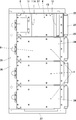
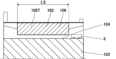
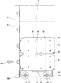
- the narrow gap inspection apparatus 1 of the present embodiment checks the narrow gap 102 in the longitudinal direction of the concrete bridge 101.
- a step portion 104 is provided on the concrete base (abut) 103 of the concrete bridge 101
- a slide shoe 105 is provided on the upper surface of the step portion 104
- the slide shoe 105 is used to The narrow gap 102 is provided between the longitudinal end face 106T of the bridge girder 106 and the vertical wall surface 104T of the step portion 104 to support the bridge girder 106.
- an expansion and contraction device 107 for closing the upper portion of the narrow gap 102 is provided between the upper surface of the base portion 103 and the upper surface of the bridge girder 106.
- a narrow gap 102 is also provided between the end faces 106T, 106T of the adjacent bridge beams 106, 106.
- the vertical wall surface 104T and the end surface 106T are inspection points. Note that at least one of the vertical wall surface 104T and the end surface 106T may be a concrete surface. Further, in FIG. 9, in order to facilitate understanding, the end face 106T which is an inspection point is hatched.
- the width WS of the narrow gap 102 is 20 mm
- the lateral width LS of the narrow gap 102 is 8450 mm
- the distance HS between the upper surface of the step portion 104 and the lower surface of the bridge girder 106 is about 150 mm.
- the narrow gap inspection apparatus 1 includes a movable body 2 that moves in the narrow gap 102 to capture an inspection point, and an apparatus main body 3 that controls the movable body 2.
- the movable body 2 is configured by arranging a plurality of main bodies 4 in parallel.
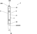
- the movable body 2 can also be configured by one main body 4.
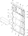
- the movable body 2 includes at least one box-shaped main body 4.
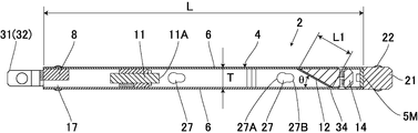
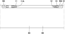
- the main body 4 is formed so that the dimension L in the length direction and the dimension W in the width direction intersecting with the dimension T in the thickness direction are larger than the dimension L in the length direction which is the movement direction It is larger than the dimension W in the width direction (L> W> T).
- the main body 4 includes a front surface 5M and a rear surface 5K located forward and backward in the traveling direction, wide side surfaces 6 and 6 located on both sides in the thickness direction, and narrow side surfaces 7 and 7 located on both sides in the width direction.
- a frame 8 is provided at the rear of the main body 4, and the frame 8 is sandwiched between the wide side faces 6, 6 and the narrow side faces 7, 7, and the rear face of the frame 8 is the rear face It constitutes 5K.
- An opening 8A is formed at the center of the frame 8.
- an imaging means 11 such as an endoscope camera or a CCD camera is provided, and the lens 11A of the imaging means 11 is disposed in the front to image the front.
- a mirror 12 is provided in front of the image pickup means 11 at a predetermined distance, and the mirror 12 is provided obliquely with respect to the length direction, and in this example, 30 degrees with respect to the length direction It is disposed at an angle ⁇ .
- the mirror 12 is provided on substantially the entire length in the width direction in the main body 4, and the angle ⁇ is 89 degrees or less, 1 degree or more, and the area for copying the inspection portion can be adjusted.
- the mirror 12 has a length dimension W1 in the width direction larger than a dimension L1 in the length direction.
- the thickness of the main body 4 is 10 mm or less.
- An imaging unit 13 is configured by the imaging means 11 and the mirror 12.
- the imaging unit 13 may include an illumination unit 14 in addition to the imaging unit 11 and the mirror 12.
- an illumination means 14 composed of an LED or the like which emits light in a bar-like shape or a plurality of point shapes. It is provided in a cross direction at an angle to the substantially full length or the length direction.
- the illumination means 14 may be provided on the rear side of the mirror 12.
- a circuit board 15 serving as a main body side control means for controlling the operation of the illumination means 14 is provided at an appropriate place such as the front face of the frame 8 or in the vicinity thereof.
- the image pickup means 11 is also electrically connected to the apparatus main body 3 by the cable 16, and the insertion portion 17 for inserting the cable 16 is formed in the length direction at the rear of the frame 8.
- the frame A groove is formed on one side surface of the rear portion 8 to form the insertion portion 17.
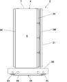
- Guide portions 21 are provided in front of the front surface portion 5M of the main body 4, and guide rollers 22, 22 made of a solid tire or the like are rotatably provided on both sides in the width direction of the guide portions 21, respectively.
- the dimension of the guide portion 21 in the thickness direction is the same as or smaller than the dimension T in the thickness direction, and the outer diameter D of the guide roller 22 is formed slightly larger than the dimension T. It is arranged so that the outer periphery of 22 may come out. Then, the focal distance can be kept constant by the guide rollers 22 and 23.
- the end portions 23S and 23S of the support shafts 23 and 23 of the guide rollers 22 and 22 on both sides are formed in a curved shape, and between the end portions 23S and 23S are set to be within the dimension W in the width direction. ing.
- step portions 24, 24 for housing the guide rollers 22 are provided, and in the step portions 24, 24 on both sides, guide rollers 22, 22 are rotatably provided. .
- the axial center of the support shaft 23 of the guide roller 22 is provided in the width direction.
- the body 4 comprises connecting means 26 connected in parallel.
- the connecting means 26 comprises a locking hole 27 provided on one side of the narrow side surface 7 and a locking projection 28 also provided on the other side of the narrow side surface 7, and the locking hole 27 extends in the length direction.
- the large diameter portion 27A and the small diameter portion 27B are continuously formed, and the locking projection 28 has a head 28A for inserting the large diameter portion 27A and a shaft portion 28B for locking to the small diameter portion 27B. In the state where the shaft portion 28B is inserted, the head portion 28A larger than the small diameter portion 27B is engaged with the small diameter portion 27B.
- the locking projection 28 is a convex locking portion, and the locking hole 27 is a concave locking portion.
- a rear connection means 31 is provided at the rear of the main body 4.
- the rear side connection means 31 includes a rear facing connection arm 32 as a backward directed longitudinal direction connecting portion disposed at intervals in the width direction, and a width direction connecting arm 33 as a width direction connecting portion projecting downward. .
- the plate-like wide side portions 6, 6 are fixed to the openings on both sides in the thickness direction of the main body 4 to close the openings, and the wide side portions 6 on the reflective surface side of the mirror 12 are closed.
- a transparent window 34 is provided corresponding to the mirror 12 and the illumination means 14.
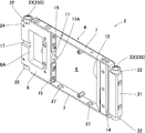
- a mounting body 35 is used in which a plurality of main bodies 4, 4.
- the mounting body 35 has a rear connection receiving portion 36 for connecting the rear connection means 31, and both ends receiving the plurality of main bodies 4, 4 ... from both sides in the width direction. It has a substantially U-shape having portions 37, 37.
- the main bodies which adjoin the width direction are connected by the said connection means 26, and the backward direction connection arm 32 and the width direction connection arm 33 of several main bodies 4 and 4 ...
- the rear connection receiving portion 36 is connected by a bolt or the like.
- the main bodies 4 and 4 of the width direction both sides and the both-ends receiving parts 37 and 37 are connected by the connection means which is not shown in figure.
- a moving body 2 is formed in which a plurality (four in this example) of the main body 4 provided with the imaging means 11, the mirror 12 and the illumination means 14 are connected, and the mirrors 12 of the four main bodies 4 are substantially continuous. Line up on the line.
- the both end receiving portions 37 have a substantially U-shaped cross section, and constitute a wire guard through which the cord-like body can be inserted.
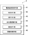
- the device body 3 operates the power supply means 41 for supplying power to the imaging means 11 and the illumination means 14 via the cable 16 to the main body 4, the control means 42 for the movable body 2, and the movable body 2.
- Operation means 43 for The operation means 43 may be provided separately from the device body 3. In this case, the device body 3 may be operated by the operation means 43 in a wired or wireless manner.
- the movable body 2 when the movable body 2 is used by moving it in the left-right direction, or when it is used by moving it up and down, the transparent window 34 is placed on the lower side and the movable body 2 is disposed in the narrow gap 102.
- Wires (not shown) are connected in advance to the both end receiving parts 37 located on the left and right sides, and the moving body 2 is moved, raised or lowered at a constant speed by using the wires on both sides.
- a rod-like member may be used to move leftward, rightward, up or down.
- the image pickup unit 11 continuously or intermittently shoots a plurality of times according to the movement amount by the control unit 42, and the photographed data is input to the recording unit 45 of the apparatus main body 3, and the image processing unit 46 A continuous image of the vertical wall surface 104T, the end face 106T) is obtained.
- the moving object 2 may be imaged while moving in the left and right direction of the narrow gap 102.
- the imaging unit 11 may be one for capturing a continuous image which is a video system, and the image processing unit 46 performs image processing on the continuous image data to obtain an image of an inspection point.
- the imaging means 11 a commercially available endoscopic camera with a focal length of about 20 to 50 mm is used, and the focal length is extended using the mirror 12, and in this example, the distance between the lens 11 A and the mirror 12 Is set to about 77 mm, which is longer than the focal length of the imaging means 11, to enable wide-range imaging.
- the mirror 12 used was 19 mm ⁇ 90 mm long in the width direction of the main body 4.
- an area of about 900 mm 2 can be photographed at 90 mm ⁇ (19 mm ⁇ sin 30 °). Furthermore, in order to shoot a wider range in one shooting (shooting), by arranging the imaging units 13 in series or in parallel, it is possible to take a plurality of photographs at the same time.
- the imaging unit 11 can use a compound eye camera (having a plurality of lenses arranged on one substrate and having a function of a dragonfly eye).
- photographing or moving picture photographing may be performed by the imaging unit 11.
- the illumination means 14 capable of recognizing a crack at the inspection point by image processing is used.
- the illumination unit 14 irradiates a large amount of light, a so-called electronic copy method or a necessary amount of light, using a unit capable of image processing.
- this illumination means 14 can irradiate light from a direction such as at right angles, parallel or circular with respect to the direction of the imaging means 11, simultaneously or in sequence, etc., and can recognize cracks by monitor or image processing It is.
- the imaging unit 11 is housed in the box-shaped main body 4.
- the photographs taken by the imaging means 11, 11 ... provided respectively in the plural juxtaposed main bodies 4, 4 ... are displayed as connected or continuous images by image processing. That is, a plurality of pieces of image data captured by the imaging unit 11 are connected to produce continuous image data, and the occurrence of a crack or the like is checked based on the image data. Moreover, what was image-formed can display a crack on an image by image processing for every width
- the imaging range at the inspection point is about 8 m in width and about 1 m in height.
- the mobile unit 2 and / or the device main body 3 is provided with a self-position recognizing unit 44 that recognizes the position in the imaging range.
- this position recognition means 44 it is possible to use a laser or a gauge (not shown) for measuring the number of rotations or the amount of movement of moving wheels to be described later.
- the own position recognition means 44 may use an encoder or the like that reads the amount of movement of the wire pulling the main body 4, the number of rotations of the wheel, and the like.
- This gauge measures the distance from the upper and lower ends of the left and right ends of the base 103 and the vertical wall surface 104T.
- light beams such as a laser are emitted from the main body 4 in the left and right and up and down directions, and the position is confirmed by receiving reflected light from a reflection plate installed in the reflection direction.
- the reflecting plate is disposed in the narrow gap 102 or in the vicinity thereof.
- the narrow gap 102 is about 20 mm, and this narrow gap 102 is narrower than the design size due to the swelling of the form at the time of putting concrete, the protrusion of the joint material of the joint portion, or free lime exuding from the concrete. Therefore, the width of the main body 4 is less than 20 mm.
- the main body 4 incorporates an imaging means 11 provided with a lens 11A, and a circuit board 15 serving as a control means for controlling the imaging means 11. Furthermore, the main body 4 uses a laser or the like of its own position recognition means 44.
- the measuring instrument sensor means, moving means for moving the main body 4 horizontally and vertically, and a removing device (not shown) for removing dirt on the lens 11A can be incorporated.
- the device body 3 controls movement and photographing of the movable body 2, and the power supply means 41 supplies power to the body 4.
- the recording means 45 has a function of obtaining and storing imaging data of the imaging means 11 and displaying an image based on the imaging data on an image monitor (not shown).
- the apparatus main body 3 and the main body 4 are electrically connected by a cable 16 for the supply of power and the input of imaging data.
- the device body 3 supplies power to these, and further, data from the instrument sensor means is obtained and stored, and based on the data
- the position of the main unit 4 is output to the image monitor. These are performed by the control of the control means 42.
- the space under the bridge 101 that is, the distance between the upper surface of the step portion 104 and the lower surface of the bridge girder 106 is about 150 mm, but the height of the back part is about 100 mm in order to make the drainage gradient. Therefore, the size of the apparatus main body 3 is, for example, about 60 mm in height, about 200 mm in the lateral direction of the bridge 101, and portable. In order to store the necessary functions in the device main body 3, when the above dimensions are exceeded, a plurality of divided device main bodies 3 are used.
- the apparatus main body 3 is provided with various output terminals. For example, an output terminal for NPSC to a monitor screen, an output terminal for a head mounted display, an output terminal for remote control, an output terminal for failure monitoring, etc. are raised. If output terminals such as these are provided, operation and failure monitoring of the entire apparatus 1 can be performed at a place away from the bridge 101 or in a car, and it is also possible to relate captured images displayed on a monitor screen. It is possible to provide a remote control device for remotely controlling the narrow gap inspection device 1 and a failure monitoring device for failure.
- the following devices can be incorporated into the device main body 3, and these may be configured to be performed by the recording means 45 and the image processing means 46 described above.
- Power supply means 41 for the mobile unit 2 means for acquiring and storing image information, and means for processing and storing image data, and supplying power to a meter sensor for checking the own position of the mobile unit 2 And means for obtaining and storing the information of the gage meter sensor and outputting the information to the monitor, and means for displaying the image based on the imaging data and the gage meter data on the monitor.
- the apparatus main body 3 can be provided with left and right driving means for driving the moving body 2 to move left and right, and vertical driving means for driving the moving body 2 to move up and down.
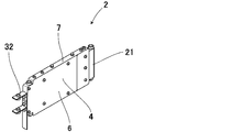
- the main body 4 includes the mirror 12 that captures the vertical wall surface 104T or the end face 106T, which is the inspection site, the illumination unit 14 that illuminates the inspection site, and the imaging unit 11 that images the inspection site that is copied to the mirror 12
- the main body 4 is formed larger in the length direction than in the thickness direction and in the width direction intersecting the length direction, and the mirror 12 is provided obliquely with respect to the length direction, and the mirror 12 has dimensions in the length direction Since the length dimension W1 in the width direction is larger than L1, the inspection portion 11 inserted in the narrow gap 102 and captured on the mirror 12 can be imaged by the imaging means 11. At this time, the mirror 12 has a dimension L1 in the length direction. Since the dimension W1 in the width direction is larger, imaging of a wide area is possible.
- the illumination means 14 can be light-controlled to make it easy to photograph a crack or the like. Furthermore, the illumination device 14 can be attached to the main body 4 by adjusting the attachment angle with respect to the imaging means 11 and the mirror 12.
- the imaging unit 13 including the mirror 12 and the imaging unit 11 is incorporated in the main body 4, and the transparent window portion 34 corresponding to the mirror 12 is provided in the main body 4.
- the transparent window portion 34 corresponding to the mirror 12 is provided in the main body 4.
- a plurality of imaging units 13 are arranged in parallel in the width direction, so that imaging can be performed in a wide range in the width direction.
- a plurality of main bodies 4 incorporating the imaging unit 13 are arranged in parallel in the width direction, so by arranging the necessary number of main bodies 4 in parallel according to the size of the inspection location. A wide range of imaging is possible at one time.
- the guide rollers 22 are provided on both sides before and after the moving direction of the main body 4 so that the inside of the narrow gap 102 can be stably moved. Furthermore, the narrow side surface portion 7 of the main body 4, 4 is provided with the connection means 26 which connects the main body 4, 4 with the locking projection 28 which is a convex locking portion and the locking hole 27 which is a concave locking portion. 7 can be connected closely without gaps. In addition, the plurality of main bodies 4 can be easily attached to the attachment body 35 by the rear side connection means 31.
- the plate-like wide side surface portions 6 and 6 are fixed to the openings on both sides in the thickness direction of the main body 4 to close the openings and the imaging unit 13 is built in the main body 4, dust can be prevented from entering. If the body 4 is made watertight and waterproof, water will not intrude inside.
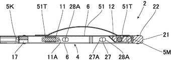
- FIG. 10 shows a second embodiment of the present invention, in which the same reference numerals are given to the same parts as the first embodiment and the detailed explanation thereof is omitted.
- a wide side surface opposite to the transparent window 34 is shown.
- the portion 6 is provided with biasing means which slides on the opposite side of the inspection point and biases the main body 4 to the inspection point side.
- a curved plate spring 51 is used as the urging means, Both ends 51 T, 51 T of the plate spring 51 are connected to the front and back of the main body 4.
- the leaf spring 51 slides and moves on the opposite surface, and the movable body 2 is moved along the inspection point side by the biasing of the leaf spring 51.
- a predetermined clearance can be obtained by the guide roller 22, and the movable body 2 can be moved at a substantially constant distance from the surface on the inspection site side.
- the inspection site needs to be cleaned.
- the width of the narrow gap 102 after the load is about 50 mm. Since the surface after hanging is extremely uneven due to aggregate (gravel), mortar or reinforcing bar, biasing by the plate spring 51 of this embodiment is effective. In addition, crawler type moving means described later is also effective.
- the main body 4 is provided with the plate spring 51 which is urging means on the opposite side of the reflection surface of the mirror 12, and the guide roller 22 which is guide means is provided.
- the mobile unit 2 can be moved.
- the plate spring 51 can be provided at an appropriate place of the movable body 2 and may be provided on the mounting body 35 other than the main body 4.
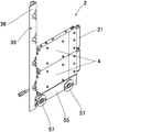
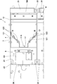
- a wheel mounting portion 52 in the front-rear direction is provided at the lower portion of the receiving portion 36.
- the wheel attachment portion 52 is equal to or less than the thickness of the main body 4 and integrally includes the upper surface portion 53, front and rear surface portions 54M and 54K provided on the front and rear of the upper surface portion 53, and one wide side surface portion 55.
- pivots 56 are provided on the front and back of the inner surface of the wide side surface portion 55, and a thin moving wheel 57 is rotatably provided on the pivot 56, and the wheel 57 is positioned at the center in the thickness direction of the wheel mounting portion 52, The lower portion of the wheel 57 is disposed downward from the lower edge of the wide side surface portion 55.
- the locking projection 28 is provided on the upper surface portion 53 of the wheel mounting portion 52. Furthermore, at the rear of the rear side connection receiving portion 36, a connecting portion 36R that detachably connects the operating rod 58 is provided. Further, the mounting body 35 is provided with a cable 16A, and the cables 16, 16 ... of the plurality of main bodies 4, 4 ... are electrically connected to the cable 16A, and the cable 16 is a device main body It is electrically connected to 3.
- the moving body 2 is configured by arranging a plurality of main bodies 4, 4... In parallel to the mounting body 35, and the wheel 57 is disposed in the narrow gap 102 in a state of contacting the upper surface of the base 103.
- the inspection site can be photographed while moving the movable body 2 by an appropriate means.
- the same operation and effect as the above-described embodiments can be obtained.
- the wheel 57 which is the traveling means is provided, stable movement of the movable body 2 becomes possible.
- the mounting body 35 is provided with a cable 16A, and the cables 16A, 16B of the plurality of main bodies 4, 4 ... are electrically connected to the cable 16A. A plurality of main bodies 4 can be connected easily.
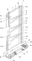
- the units 13 have a size that can be accommodated side by side and can be stored, and as shown in the figure, the length in the width direction of the main body 4 is formed larger than that of the first embodiment.
- partition plates 61, 61A,... Connecting the rear surface portion 5K and the front surface portion 5M are provided, and the partition plates 61, 61A at positions sandwiching the imaging means 11 are arranged to spread from the rear side to the front side.
- a guide roller 62 is provided on the upper narrow side surface portion 6, and a bottom portion 63 made of a plate material larger in the front-rear direction than the distance between the front and rear surface portions 5M and 5K is provided on the lower portion of the main body 4.
- a pair of guide rollers 62 are provided at the front and rear, respectively.
- One guide roller 62 is disposed at one side in the width direction
- the other guide roller 62 is disposed at the other side in the width direction
- the guide rollers 62 at one side in the width direction The other guide roller 62 in the width direction rolls on the other surface of the narrow portion 102.
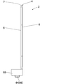
- a traveling means 64 is provided on one side of the bottom portion 63.
- This traveling means 64 is an endless track, and is provided with toothed pulleys 65, 65 at the front and back of the bottom, and an endless belt 66 is hooked on these toothed pulleys 65, 65.
- the uneven portion 67 engaged with the pulley 65 is provided, and the outer surface of the endless belt 66 is formed with an uneven portion 67A for anti-slip.
- one of the toothed pulleys 65 is rotationally driven by a drive motor 68 which is drive means.
- the height of the endless belt 66 is smaller than the distance HS between the upper surface of the step portion 104 and the lower surface of the bridge beam 106 and is 100 mm or less.
- the traveling means 64 is driven by the control of the apparatus main body 3. Further, the upper part and the central part of the traveling means 64 are covered by a box-like case 69.
- the traveling means 64 is driven by the apparatus main body 3, While moving 2 in the left-right direction, the imaging of the inspection point can be performed and the imaging data can be sent to the apparatus main body 3.
- the same operation and effect as the above-described embodiments can be obtained. Further, in this example, it is possible to perform imaging in a wide range in the width direction in which the plurality of imaging units 13 are arranged in parallel in the width direction on the main body 4. Furthermore, since the moving means is an endless track, stable traveling is possible using the space between the upper surface of the step portion 104 and the lower surface of the bridge girder 106.
- FIG. 20 shows a fifth embodiment of the present invention, in which the same reference numerals as in the above embodiments denote the same parts, and a detailed description thereof will be omitted.
- rails used for the moving body 2 are shown.
- the wheels provided on the lower part of the movable body 2 on the rails travel, and the sliding member in the form of a slide slides so that the movable body 2 can move.
- a U-shaped or U-shaped rail 71 is laid on the upper surface of the base portion 103 in order to prevent the imaging from being disturbed when traveling on the uneven surface by the wheel 57 or a sliding member in the form of a sled.
- the rail 71 has vertical surface portions 73, 73 on both sides of the bottom surface portion 72.
- the openings 74 are provided in at least one and preferably both vertical surface portions 73 to secure the field of view, and the shape of the openings 74 is rectangular, circular, mesh-like It can be done. In the case of a mesh, the mesh is an opening.
- the heights of the vertical surface portions 73 on the both sides are made the same, and the vertical surface portions 73 on the inspection portion side are lowered to secure the visibility. There is.
- the heights of the vertical surface portions 73, 73 on both sides are lowered so as not to disturb the view.
- the rail 71 of 2 to 8 m in length secures a strength that does not cause a bend that may cause a hindrance to the movement of the movable body 2 by bending, deformation, and the like.
- the rail 71 facilitates the movement of the wheel, the sliding member, and the like.
- FIG. 21 shows a sixth embodiment of the present invention, in which the same reference numerals are given to the same portions as those in the above-mentioned respective embodiments, and the description thereof is omitted to describe in detail.
- the parts 7 and 7 are connected by a universal joint 76.
- the vertical wall surface 104T and the end surface 106T which are inspection points may have unevenness of the concrete form during manufacture, burrs of the form, or unevenness due to concrete free lime. If the moving body 2 can not follow these, the moving body 2 may be caught in the narrow gap 102 and may not be able to move. Therefore, by connecting the main bodies 4 and 4 freely by the universal joint 76 serving as the connecting means, that is, the main bodies 4 and 4 are connected so as to be able to swing, it is possible to follow the unevenness of the narrow gap 102.
- FIG. 22 shows a seventh embodiment of the present invention.
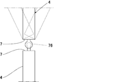
- a mechanism for movement is contained in the main body 4
- the helical portion 82 is provided on the vertically installed main shaft 81 and a rotational driving means 83 for rotationally driving the main shaft 81 is provided.
- a screwing portion 84 screwed to 82 is provided, and the moving body 2 is moved up and down by the rotational sliding action of the spiral portion 82 and the screwing portion 84. This eliminates the need to provide a moving mechanism in the main body 4.
- a removing device (not shown) for removing dust attached to the spiral portion 82 and the screwing portion 84.
- the power supply of the rotational drive means 83 for rotationally driving the main shaft 81 is incorporated in the apparatus main body 3.
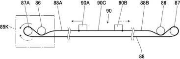
- the movable body 2 is configured by attaching the main bodies 4, 4, 4 of the base).
- the driving means 85 of the movable body 2 is detachably provided.
- the driving means 85 includes a case 85 K, and the height of the case 85 K is formed smaller than the distance HS between the upper surface of the step 104 and the lower surface of the bridge 106, and the case 85 K is the upper surface of the step 104 and the bridge 106 It can also be used by placing it on the lower surface of
- the driving means 85 has the following configuration.
- One end of the rail 71 is connected to the case 85 K, and a guide wheel 86 and a driven wheel 87 are provided on the other end of the rail 71 so as to be able to idle.
- the guide wheel 86 and the driven wheel 87 are covered by a cover not shown.
- an electric motor 89 as a movement drive means for operating the movement wire 88 is incorporated, and at one end of the rail 71, a drive wheel 87A rotationally driven by the motor 89, and a freely rotatable guide A ring 86 is provided.
- a movable body receiving member 90 moving along the rail 71 is provided, and the movable body receiving member 90 couples the one side portion 90A and the other side portion 90B to the central portion 90C along the bottom portion 72 of the rail 71.
- the lower portion of the movable body 2 is detachably connected between the one side 90A and the other side 90B.
- wheels are provided on both sides in the left-right direction of the movable body receiving member 90 or the movable body 2. When the wheel is provided in the moving body receiving portion 90, a wheel (not shown) is provided on the one side portion 90A and the other side portion 90B.
- a moving wire 88 is disposed along the rail 71, and the other end 88B of the moving wire 88 is passed around the lower portion of the guide ring 86 on the other end side, and is wound around the driven wheel 87 and folded back.
- the other end 88B of the moving wire 88 hung on the driven wheel 87 is connected to the other end 90B.
- one end 88A of the moving wire 88 passes through the lower part of the guide wheel 86 in the case 85K and is looped over the drive wheel 87A and folded back, and one end 88A of the moving wire 88 looped around the drive wheel 87A. Is connected to the one end.
- An encoder 91 for detecting the number of revolutions of the motor 89 is incorporated in the case 85K. Then, the driving wheel 87A is rotationally driven by the motor 89 and the moving wire 88 is pulled in one direction or the other direction, whereby the moving body 2 moves in the left and right direction. In this case, the number of rotations of the motor 89 is detected by the encoder 91, the amount of movement of the movable body 2 can be detected from this number of rotations, and the position of the movable body 2 can be detected from this amount of movement.
- the lower part of the movable body 2 is slidingly moved along the inside of the rail 71, or wheels (not shown) provided on the left and right lower parts of the movable body 2 are rolled in the rail 71 to move the movable body 2 It may be configured to move left and right.
- the movable body 2 can be moved to the left and right in the narrow gap 102 by the driving means 85 having the above configuration. In this case, it is possible to perform imaging of one of the vertical wall portion 104T and the end surface 106T which are inspection points.
- the drive means 85 is provided on one side in the left-right direction of one end of the rail 71, whereas the case 85K incorporating the drive means 85 operates attachment / detachment with the rail 71.
- An operation button 85K is provided, and by operating the operation button 85K, as shown by an alternate long and short dash line in FIG. 23, the case 85K is provided to be connected to the other side of one end of the rail 71 in the left and right direction 85 can be coupled to the drive wheel 87A.
- the case 85K is provided on the other side in the left-right direction of one end of the rail 71, the rail 71 and the movable body 2 are reversed horizontally and set in the narrow gap 102, and the case 85K is mounted on the upper surface of the step 104 and the bridge girder. It can be disposed between the lower surface of 106. Then, the moving body 2 can perform imaging of the other of the vertical wall portion 104T and the end surface 106T.
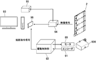
- the control unit 42 is provided with a drive control unit 92, and the drive control unit 92 is incorporated in the drive unit 85 or the device body 3.
- the drive control unit 92 controls the movable body 2 moving along the rail 71, controls the drive of the motor 89 based on the position information from the encoder 91, and takes a photographing command signal at every fixed movement distance interval.
- An image capturing instruction is issued to a personal computer 93 generated by the imaging unit 11 and constituting a part of the control unit 42.
- the image signal distributor 94 is provided with the image data from the image pickup means 11, specifically an NTSC ⁇ 4 channel signal, which is part of the personal computer 93 and the recording means 45. It distributes to the recorder 95.
- the image capturing board 95 is provided, and the image capturing board 95 is a substrate for capturing the NTSC signal from the imaging means 11 into the personal computer 93.
- the personal computer 93 constitutes a part of the control means 42 and the image processing means 46, and image processing software is installed.
- This image processing software sequentially stores images by the input of a photographing command signal generated at a fixed distance section (take-in interval) as the imaging unit 11 moves.
- the images stored in this way are combined at offset intervals after capture and combined to obtain a continuous combined image. This combined image makes it possible to grasp rough cracks at the site.
- the moving picture recorder 95 has a function of simultaneously storing the image even in the moving picture format and performing post-processing (screen connection and confirmation of a crack location) in an office other than the site, for example, away from the site.
- post-processing screen connection and confirmation of a crack location
- the same operation and effect as the above-described embodiments can be obtained.
- the drive means 85 provided with the motor 89, the rail 71, and the movable body receiving member 90 to which the movable body 2 can be attached and detached is used, installation at the site becomes easy and highly convenient.
- the endless moving wire 88 is hooked on the driving wheel 87A by connecting to the moving body receiving member 90, and the driving wheel 87A is rotationally driven by the motor 89 to move the moving body 2
- the position of the moving body 2 can be detected by detecting the rotation of the motor 89 by the encoder 91.
- 26 to 28 show a ninth embodiment of the present invention, in which the same reference numerals as in the above embodiments denote the same parts, and a detailed description thereof will be omitted.
- software used for the personal computer 93 A modification of the control of the apparatus, the image processing and the like will be described.
- the moving body 2 is inserted into the narrow gap 102 of about 20 mm minimum between the base of the expressway concrete bridge and the bridge pier, and the respective end faces (vertical wall portion 104T and end face 106T) of the base and the bridge foot are imaged.
- the end face portion projected on the mirror 12 in the captured image is the necessary part.
- the wheel 57 is provided in the mobile unit 2 in which four main units 4 are connected, and the wheel 57 is inserted into the narrow gap 102 between the base and the bridge leg of the concrete bridge 101.
- the imaging portion is only one of the vertical wall portion 104T and the end face 106T, imaging on the opposite side can be performed by attaching the movable body 2 upside down or reversing the lateral direction.
- the mobile unit 2 including the four imaging units 11 will be described by way of example.
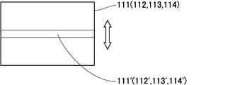
- the four imaging units 11 sequentially display the NTSC of four screens 111, 112, 113, and 114 from the top.
- the signal is captured.
- Necessary parts (parts displayed on the mirror 12) 111 ', 112', 113 'and 114' are cut out on the screens 111, 112, 113 and 114, and displayed on the monitor 115 as shown on the upper right of FIG. Thereby, the imaging state in the same place can be confirmed.
- the moving body 2 is driven to travel by a motor, and the moving distance can be known by the encoder 91.
- a capture command is transmitted to the capture board according to the capture interval (predetermined interval) set by the control of the mobile unit 2, and images are sequentially saved at the timing of the received capture command.
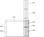
- the images of the necessary parts 111 ', 112', 113 'and 114' are combined. Since the obtained coupling becomes a huge surface, it is controlled to scroll vertically and horizontally on the monitor 115 as a display means.
- necessary portions 111 ', 112', 113 'and 114' are coupled by shifting necessary portions by a fixed pixel value according to the capture interval. Further, the four combined images are further arranged vertically to form one image.
- the monitor 115 is provided with a scroll bar 116 and can scroll the image up and down. Further, a scale 117 is provided on the monitor to know the display position, and this scale 117 makes it possible to know which part of the whole image the monitor 115 is displaying.
- the combination of the images may be an automatic combination by feature extraction. In the case of such automatic coupling, an external capture command is unnecessary.
- the image may be scaled in the X direction according to the total movement distance. Furthermore, it is preferable to be able to adjust the conversion between the pixels on the screen and the actual size as needed.
- the combined screen may be confirmed, and the above portion such as a crack may be marked and displayed by image processing.
- the control part of the mobile unit 2 can be operated using the control box or the like, various controls may be processed and operated by the software side. In this case, the command is determined and the software is inserted.
- the personal computer 93 is connected via USB or serial to a control box (case 85K) or the like.
- FIG. 29 shows a tenth embodiment of the present invention, in which the same reference numerals as in the above embodiments denote the same parts, and a detailed description thereof will be omitted.
- the slopes 121, 121 are provided so as to sandwich the plurality of lighting means 122... Are provided on the slopes 121, 121, and the lighting means 122. Illumination light in the orthogonal direction is irradiated to the mirror 12, and the inspection light is illuminated by the reflected light of the mirror 12.
- the slopes 121 and 121 on both sides form an angle of 45 degrees with respect to the front-rear direction, but this angle and the distance from the imaging unit 11 and the mirror 12 can be selected as appropriate.
- the present invention is not limited to the present embodiment, and various modifications can be made within the scope of the present invention.
- various connection means can be used as long as they connect the main bodies.
Landscapes
- General Health & Medical Sciences (AREA)
- Health & Medical Sciences (AREA)
- Life Sciences & Earth Sciences (AREA)
- Chemical & Material Sciences (AREA)
- Analytical Chemistry (AREA)
- Biochemistry (AREA)
- Physics & Mathematics (AREA)
- General Physics & Mathematics (AREA)
- Immunology (AREA)
- Pathology (AREA)
- Investigating Materials By The Use Of Optical Means Adapted For Particular Applications (AREA)
- Length Measuring Devices By Optical Means (AREA)
- Bridges Or Land Bridges (AREA)
Applications Claiming Priority (2)
| Application Number | Priority Date | Filing Date | Title |
|---|---|---|---|
| JP2013208558A JP5992893B2 (ja) | 2013-10-03 | 2013-10-03 | 狭隙間点検装置 |
| JP2013-208558 | 2013-10-03 |
Publications (1)
| Publication Number | Publication Date |
|---|---|
| WO2015049885A1 true WO2015049885A1 (ja) | 2015-04-09 |
Family
ID=52778485
Family Applications (1)
| Application Number | Title | Priority Date | Filing Date |
|---|---|---|---|
| PCT/JP2014/055862 Ceased WO2015049885A1 (ja) | 2013-10-03 | 2014-03-06 | 狭隙間点検装置 |
Country Status (2)
| Country | Link |
|---|---|
| JP (1) | JP5992893B2 (enExample) |
| WO (1) | WO2015049885A1 (enExample) |
Families Citing this family (7)
| Publication number | Priority date | Publication date | Assignee | Title |
|---|---|---|---|---|
| JP6661071B2 (ja) * | 2015-08-12 | 2020-03-11 | 国立大学法人佐賀大学 | 壁面撮像装置 |
| WO2017057356A1 (ja) * | 2015-09-28 | 2017-04-06 | 倉敷紡績株式会社 | 構造物撮像装置、構造物検査装置および構造物検査システム |
| JP6602624B2 (ja) * | 2015-09-28 | 2019-11-06 | 倉敷紡績株式会社 | 構造物検査システム |
| WO2018134991A1 (ja) | 2017-01-23 | 2018-07-26 | 三菱電機株式会社 | 無限軌道走行装置、及び移動体 |
| KR101938860B1 (ko) * | 2018-04-17 | 2019-01-16 | 주식회사 제이더블유이앤씨 | 콘크리트 구조물의 탄산화 깊이 측정장치 |
| EP3786036B1 (en) | 2018-04-23 | 2022-05-11 | Mitsubishi Electric Corporation | Endless track traveling device and moving body for generator inspection robot equipped with same |
| CN112378359A (zh) * | 2021-01-15 | 2021-02-19 | 潍坊凯速建筑科技有限公司 | 一种装配式建筑的pc构件厚度检测装置 |
Citations (5)
| Publication number | Priority date | Publication date | Assignee | Title |
|---|---|---|---|---|
| JPS61135247U (enExample) * | 1985-02-12 | 1986-08-23 | ||
| JPS63169542A (ja) * | 1987-01-07 | 1988-07-13 | Tokyu Constr Co Ltd | コンクリ−ト構造物に於ける表面異常の検査方法 |
| JPH02149839A (ja) * | 1988-12-01 | 1990-06-08 | Tokyu Constr Co Ltd | 遠隔撮影装置 |
| JPH0687853U (ja) * | 1993-06-01 | 1994-12-22 | 石川島播磨重工業株式会社 | 配管検査装置 |
| JP2005024260A (ja) * | 2003-06-30 | 2005-01-27 | Tokyo Electric Power Co Inc:The | コンクリート構造物の検査用撮影装置 |
Family Cites Families (4)
| Publication number | Priority date | Publication date | Assignee | Title |
|---|---|---|---|---|
| JPS60107818U (ja) * | 1983-12-19 | 1985-07-22 | 三菱重工業株式会社 | 構造物内部簡易検知器 |
| JP3276621B2 (ja) * | 1999-11-11 | 2002-04-22 | 計測検査株式会社 | トンネルの内部壁面のひび割れ検出方法 |
| JP2002243649A (ja) * | 2001-02-16 | 2002-08-28 | Ishikawajima Harima Heavy Ind Co Ltd | 外観検査装置 |
| JP5372644B2 (ja) * | 2009-07-30 | 2013-12-18 | オリンパス株式会社 | 内視鏡 |
-
2013
- 2013-10-03 JP JP2013208558A patent/JP5992893B2/ja active Active
-
2014
- 2014-03-06 WO PCT/JP2014/055862 patent/WO2015049885A1/ja not_active Ceased
Patent Citations (5)
| Publication number | Priority date | Publication date | Assignee | Title |
|---|---|---|---|---|
| JPS61135247U (enExample) * | 1985-02-12 | 1986-08-23 | ||
| JPS63169542A (ja) * | 1987-01-07 | 1988-07-13 | Tokyu Constr Co Ltd | コンクリ−ト構造物に於ける表面異常の検査方法 |
| JPH02149839A (ja) * | 1988-12-01 | 1990-06-08 | Tokyu Constr Co Ltd | 遠隔撮影装置 |
| JPH0687853U (ja) * | 1993-06-01 | 1994-12-22 | 石川島播磨重工業株式会社 | 配管検査装置 |
| JP2005024260A (ja) * | 2003-06-30 | 2005-01-27 | Tokyo Electric Power Co Inc:The | コンクリート構造物の検査用撮影装置 |
Also Published As
| Publication number | Publication date |
|---|---|
| JP5992893B2 (ja) | 2016-09-14 |
| JP2015072220A (ja) | 2015-04-16 |
Similar Documents
| Publication | Publication Date | Title |
|---|---|---|
| WO2015049885A1 (ja) | 狭隙間点検装置 | |
| CA2488301C (en) | Laser survey device | |
| RU2445571C1 (ru) | Устройство для измерения параметров пересечений | |
| JP2004347585A (ja) | 建築および土木構造物計測・解析システム | |
| JP6602625B2 (ja) | 構造物検査システム | |
| JP4567533B2 (ja) | パンタグラフのすり板検査装置 | |
| JP6602624B2 (ja) | 構造物検査システム | |
| JP2004309491A (ja) | 建築および土木構造物計測・解析システム | |
| KR101745988B1 (ko) | 차량 하부 촬영시스템 | |
| JP5298929B2 (ja) | 架線検測装置 | |
| JP6392642B2 (ja) | 狭隙間点検装置のレール装置 | |
| JP6482248B2 (ja) | 狭隙間点検装置 | |
| JP2004187220A (ja) | ひび割れ検査装置のカメラ画角調整方法 | |
| KR102195061B1 (ko) | 통로형 구조물의 검사방법 | |
| WO2017057356A1 (ja) | 構造物撮像装置、構造物検査装置および構造物検査システム | |
| JP2004352107A (ja) | 鉄道設備管理装置 | |
| JP6950948B2 (ja) | 構造物点検装置 | |
| KR100816826B1 (ko) | 레이저 이미지를 이용한 균열측정 장치 및 방법 | |
| JP6661071B2 (ja) | 壁面撮像装置 | |
| JP2004309492A (ja) | 建築および土木構造物計測・解析システム | |
| JP6446691B2 (ja) | 埋設中空構造物内検査方法及び埋設中空構造物内検査装置 | |
| JP4551990B2 (ja) | パノラマ映像作成方法と作成装置 | |
| JPH03212610A (ja) | 走行検査装置 | |
| JP7517876B2 (ja) | 点検装置、および、点検システム | |
| KR101210737B1 (ko) | 영상 취득 시스템 |
Legal Events
| Date | Code | Title | Description |
|---|---|---|---|
| 121 | Ep: the epo has been informed by wipo that ep was designated in this application |
Ref document number: 14850574 Country of ref document: EP Kind code of ref document: A1 |
|
| NENP | Non-entry into the national phase |
Ref country code: DE |
|
| 122 | Ep: pct application non-entry in european phase |
Ref document number: 14850574 Country of ref document: EP Kind code of ref document: A1 |