WO2015049860A1 - 燃料電池用セパレーターおよび燃料電池 - Google Patents
燃料電池用セパレーターおよび燃料電池 Download PDFInfo
- Publication number
- WO2015049860A1 WO2015049860A1 PCT/JP2014/004992 JP2014004992W WO2015049860A1 WO 2015049860 A1 WO2015049860 A1 WO 2015049860A1 JP 2014004992 W JP2014004992 W JP 2014004992W WO 2015049860 A1 WO2015049860 A1 WO 2015049860A1
- Authority
- WO
- WIPO (PCT)
- Prior art keywords
- groove
- cooling water
- separator
- central region
- fuel cell
- Prior art date
- Legal status (The legal status is an assumption and is not a legal conclusion. Google has not performed a legal analysis and makes no representation as to the accuracy of the status listed.)
- Ceased
Links
Images


Classifications
-
- H—ELECTRICITY
- H01—ELECTRIC ELEMENTS
- H01M—PROCESSES OR MEANS, e.g. BATTERIES, FOR THE DIRECT CONVERSION OF CHEMICAL ENERGY INTO ELECTRICAL ENERGY
- H01M8/00—Fuel cells; Manufacture thereof
- H01M8/02—Details
- H01M8/0202—Collectors; Separators, e.g. bipolar separators; Interconnectors
- H01M8/0247—Collectors; Separators, e.g. bipolar separators; Interconnectors characterised by the form
- H01M8/0254—Collectors; Separators, e.g. bipolar separators; Interconnectors characterised by the form corrugated or undulated
-
- H—ELECTRICITY
- H01—ELECTRIC ELEMENTS
- H01M—PROCESSES OR MEANS, e.g. BATTERIES, FOR THE DIRECT CONVERSION OF CHEMICAL ENERGY INTO ELECTRICAL ENERGY
- H01M8/00—Fuel cells; Manufacture thereof
- H01M8/02—Details
- H01M8/0202—Collectors; Separators, e.g. bipolar separators; Interconnectors
- H01M8/0258—Collectors; Separators, e.g. bipolar separators; Interconnectors characterised by the configuration of channels, e.g. by the flow field of the reactant or coolant
- H01M8/026—Collectors; Separators, e.g. bipolar separators; Interconnectors characterised by the configuration of channels, e.g. by the flow field of the reactant or coolant characterised by grooves, e.g. their pitch or depth
-
- H—ELECTRICITY
- H01—ELECTRIC ELEMENTS
- H01M—PROCESSES OR MEANS, e.g. BATTERIES, FOR THE DIRECT CONVERSION OF CHEMICAL ENERGY INTO ELECTRICAL ENERGY
- H01M8/00—Fuel cells; Manufacture thereof
- H01M8/02—Details
- H01M8/0202—Collectors; Separators, e.g. bipolar separators; Interconnectors
- H01M8/0258—Collectors; Separators, e.g. bipolar separators; Interconnectors characterised by the configuration of channels, e.g. by the flow field of the reactant or coolant
- H01M8/0263—Collectors; Separators, e.g. bipolar separators; Interconnectors characterised by the configuration of channels, e.g. by the flow field of the reactant or coolant having meandering or serpentine paths
-
- H—ELECTRICITY
- H01—ELECTRIC ELEMENTS
- H01M—PROCESSES OR MEANS, e.g. BATTERIES, FOR THE DIRECT CONVERSION OF CHEMICAL ENERGY INTO ELECTRICAL ENERGY
- H01M8/00—Fuel cells; Manufacture thereof
- H01M8/02—Details
- H01M8/0202—Collectors; Separators, e.g. bipolar separators; Interconnectors
- H01M8/0267—Collectors; Separators, e.g. bipolar separators; Interconnectors having heating or cooling means, e.g. heaters or coolant flow channels
-
- H—ELECTRICITY
- H01—ELECTRIC ELEMENTS
- H01M—PROCESSES OR MEANS, e.g. BATTERIES, FOR THE DIRECT CONVERSION OF CHEMICAL ENERGY INTO ELECTRICAL ENERGY
- H01M8/00—Fuel cells; Manufacture thereof
- H01M8/24—Grouping of fuel cells, e.g. stacking of fuel cells
- H01M8/241—Grouping of fuel cells, e.g. stacking of fuel cells with solid or matrix-supported electrolytes
-
- H—ELECTRICITY
- H01—ELECTRIC ELEMENTS
- H01M—PROCESSES OR MEANS, e.g. BATTERIES, FOR THE DIRECT CONVERSION OF CHEMICAL ENERGY INTO ELECTRICAL ENERGY
- H01M8/00—Fuel cells; Manufacture thereof
- H01M8/24—Grouping of fuel cells, e.g. stacking of fuel cells
- H01M8/2457—Grouping of fuel cells, e.g. stacking of fuel cells with both reactants being gaseous or vaporised
-
- H—ELECTRICITY
- H01—ELECTRIC ELEMENTS
- H01M—PROCESSES OR MEANS, e.g. BATTERIES, FOR THE DIRECT CONVERSION OF CHEMICAL ENERGY INTO ELECTRICAL ENERGY
- H01M8/00—Fuel cells; Manufacture thereof
- H01M8/24—Grouping of fuel cells, e.g. stacking of fuel cells
- H01M8/2465—Details of groupings of fuel cells
- H01M8/2483—Details of groupings of fuel cells characterised by internal manifolds
-
- H—ELECTRICITY
- H01—ELECTRIC ELEMENTS
- H01M—PROCESSES OR MEANS, e.g. BATTERIES, FOR THE DIRECT CONVERSION OF CHEMICAL ENERGY INTO ELECTRICAL ENERGY
- H01M8/00—Fuel cells; Manufacture thereof
- H01M8/10—Fuel cells with solid electrolytes
- H01M2008/1095—Fuel cells with polymeric electrolytes
-
- Y—GENERAL TAGGING OF NEW TECHNOLOGICAL DEVELOPMENTS; GENERAL TAGGING OF CROSS-SECTIONAL TECHNOLOGIES SPANNING OVER SEVERAL SECTIONS OF THE IPC; TECHNICAL SUBJECTS COVERED BY FORMER USPC CROSS-REFERENCE ART COLLECTIONS [XRACs] AND DIGESTS
- Y02—TECHNOLOGIES OR APPLICATIONS FOR MITIGATION OR ADAPTATION AGAINST CLIMATE CHANGE
- Y02E—REDUCTION OF GREENHOUSE GAS [GHG] EMISSIONS, RELATED TO ENERGY GENERATION, TRANSMISSION OR DISTRIBUTION
- Y02E60/00—Enabling technologies; Technologies with a potential or indirect contribution to GHG emissions mitigation
- Y02E60/30—Hydrogen technology
- Y02E60/50—Fuel cells
Definitions
- the present invention relates to a fuel cell separator and a fuel cell.
- the fuel cell has a stack structure in which a plurality of fuel cells serving as a power generation unit are stacked, and each fuel cell sandwiches a membrane electrode assembly between opposing separators.
- the fuel gas gas flow path and the cooling water flow path can be formed by multiple streaks by press molding or by providing a plurality of protrusions.
- a method for forming the separator on the front and back surfaces is proposed in, for example, International Publication No. WO2012 / 160607.
- the cooling water flow path proposed in the above-mentioned patent document allows the cooling water to pass through while changing the direction of the flow of the cooling water due to the height of the convex part and the groove bottom part, thereby improving the diffusibility and distribution of the cooling water. Can do.
- the cooling water passes through the parts having the heights of the convex part and the groove bottom part while changing the direction of the flow, stagnation can occur in the flow of the cooling water.
- the cooling water flow channel After the start of the operation of the fuel cell, the cooling water flow channel has already spread and the flow channel is filled with the cooling water, so there is no particular problem even if the cooling water flow is stagnation.
- air remains in the cooling water flow path when the fuel cell is assembled, and that the following new problem may occur.
- a fuel cell separator is a fuel cell separator having a first surface and a second surface forming the back surface of the first surface, which are assembled to a membrane electrode assembly, A first surface including a central region facing the power generation possible region of the electrode assembly, an ascending outer edge from the central region to a peripheral edge, and a plurality of grooves formed in the central region in the first surface
- the second surface side concave groove portion including a plurality of grooves formed in the central region on the second surface, and the first surface side concave groove portion
- a central region and the outer edge portion communicate with each other, and an air discharge portion for discharging air in the groove of the second surface side concave groove portion from the central region together with the cooling water to the outer edge portion.
- air in the groove of the second surface side concave groove portion can accumulate on the upper end side of the central region. It is formed in the place. According to the fuel cell separator according to the first aspect, even if the air in the groove of the second surface side concave groove portion accumulates at the upper end side of the central region of the separator, the air discharge portion provided at a place where the air accumulation occurs. As a result, air can be discharged to the outer edge portion, and air accumulation on the upper end side of the separator central region can be avoided.
- the fuel cell separator according to the first aspect further includes a cooling water supply side manifold at the outer edge portion on one side in the horizontal direction of the central region, and the cooling water supplied from the cooling water supply side manifold. And a cooling water introduction part that diffuses and introduces the water into each of the grooves on the second surface side while changing the flow direction of the cooling water, and the air discharge part is on the upper end side of the central region. And it may be formed in the central area corner part located in the side of the above-mentioned cooling water introduction part. In the cooling water introduction part, since the cooling water passes while changing the direction of the flow, air accumulation may occur on the upper side of the cooling water introduction part. According to the fuel cell separator according to the first aspect, This air accumulation can be avoided more by the air discharge portion located at the corner portion of the separator central region.
- a fuel gas supply side manifold that supplies fuel gas into the groove of the first surface side groove portion at the outer edge portion above the cooling water supply side manifold. You may make it have.
- the fuel gas is always supplied into the groove of the first surface side concave groove portion, so that in the form of the fuel cell having the fuel cell separator according to the first aspect, The electrochemical reaction for power generation is promoted, and heat generation by this electrochemical reaction is activated.
- the side of the fuel gas supply side manifold close to the separator central region corner portion by avoiding air accumulation at the separator central region corner portion above the cooling water introduction portion. Can be cooled sufficiently.
- the groove of the first surface side groove portion and the groove of the second surface side groove portion are formed by forming a plurality of concave and convex stripes by press molding with respect to the central region.
- the fuel cell according to the second aspect in the first separator sandwiching the membrane electrode assembly, an air pool at the upper end side of the central region of the separator can be avoided in each fuel cell. It is possible to suppress a cooling failure due to being present. Moreover, according to the fuel cell which concerns on a 2nd aspect, since the 1st separator which has an air discharge part should just be replaced in the existing fuel cell, its manufacturing cost can be reduced, and an air pool is It is possible to easily eliminate or suppress a cooling problem caused by the existence.
- the first-surface-side groove in the central region of the first separator can be used as a gas flow path for supplying the membrane electrode assembly.
- the bottom wall of the first surface side groove portion of the first separator of one of the fuel cells stacked adjacent to each other is brought into contact with the second separator of the other fuel cell, so that the second surface side is recessed.
- the groove portion is closed, and the closed second surface side groove portion can be used as a cooling water flow path through which the cooling water passes.
- the present invention can be realized in various forms, for example, in the form of a fuel cell manufacturing method or a fuel battery cell.
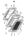
- FIG. 2 is a schematic perspective view showing an exploded configuration of a unit cell 100.
- 3 is a schematic plan view showing a configuration of an anode separator 120.
- FIG. It is a schematic perspective view which expands and shows the formation condition of the flow-path groove
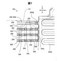
- FIG. 6 is an explanatory diagram showing a further enlargement of the flow channel groove formation state in the corner portion DC of the separator central region 121 on the fuel gas supply hole 122IN side shown in FIG. 5 in plan view from the cooling surface side.
- FIG. 9 is a schematic cross-sectional view of the fuel cell 10 taken along line 9-9 at the enlarged portion C of FIG. It is explanatory drawing which expands further in planar view from the cooling surface side, and shows the formation condition of the flow-path groove
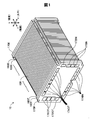
- FIG. 1 is a schematic perspective view showing the configuration of a fuel cell 10 as an embodiment of the present invention.
- the fuel cell 10 has a stack structure in which a plurality of unit cells 100 as fuel cells are stacked in the Z direction (hereinafter also referred to as “stacking direction”) and sandwiched between a pair of end plates 170F and 170E.
- the fuel cell 10 has a front end side terminal plate 160F between a front end side end plate 170F and the unit cell 100 with a front end side insulating plate 165F interposed therebetween.
- the fuel cell 10 has a rear end side terminal plate 160E between the rear end side end plate 170E and the unit cell 100 with a rear end side insulating plate 165E interposed therebetween.
- the unit cell 100, the terminal plates 160F and 160E, the insulating plates 165F and 165E, and the end plates 170F and 170E each have a plate structure having a substantially rectangular outer shape, and the long sides are in the x direction (horizontal direction). ) And the short side is arranged along the y direction (vertical direction, vertical direction).
- the end plate 170F, the insulating plate 165F, and the terminal plate 160F on the front end side include a fuel gas supply hole 172IN and a fuel gas discharge hole 172OT, a plurality of oxidant gas supply holes 174IN and an oxidant gas discharge hole 174OT, and a plurality of cooling waters. It has a supply hole 176IN and a cooling water discharge hole 176OT. These supply / discharge holes are connected to respective holes (not shown) provided at corresponding positions of the unit cells 100 to constitute gas / cooling water supply / discharge manifolds corresponding to the respective holes.
- these supply / discharge holes are not provided in the end plate 170E, the insulating plate 165E, and the terminal plate 160E on the rear end side. This is because the reaction gas (fuel gas, oxidant gas) and cooling water are supplied from the front end plate 170F to each unit cell 100 via the supply manifold, while the exhaust gas from each unit cell 100 is discharged.
- the fuel cell is a type that discharges discharged water from the front end side end plate 170F to the outside through a discharge manifold.
- the present invention is not limited to this, for example, a type in which reaction gas and cooling water are supplied from the end plate 170F on the front end side, and exhaust gas and discharge water are discharged to the outside from the end plate 170E on the rear end side.
- the plurality of oxidant gas supply holes 174IN are arranged along the x direction (long side direction) at the outer edge of the lower end of the front end side end plate 170F, and the plurality of oxidant gas discharge holes 174OT are arranged at the outer edge of the upper end. It is arrange
- the fuel gas supply hole 172IN is arranged at the upper end portion in the y direction (short side direction) of the outer edge portion of the right end of the front end side end plate 170F, and the fuel gas discharge hole 172OT is arranged in the y direction of the outer edge portion of the left end. It is arranged at the lower end.
- the plurality of cooling water supply holes 176IN are arranged along the y direction below the fuel gas supply holes 172IN, and the plurality of cooling water discharge holes 176OT are arranged in the y direction above the fuel gas discharge holes 172OT. They are arranged side by side.
- the two cooling water supply holes 176IN on the upper side of the row of cooling water supply holes 176IN are positioned so as to face the two cooling water discharge holes 176OT on the lower side of the row of cooling water discharge holes 176OT.
- a part of 176IN and the cooling water discharge hole 176OT overlap in the y direction (vertical direction) with the separator central region 121 interposed therebetween.
- the front end side terminal plate 160F and the rear end side terminal plate 160E are power collecting plates for the generated power of each unit cell 100, and output the power collected from terminals not shown to the outside.
- the anode-side separator 120 includes a plurality of groove-shaped fuel gas flow paths on the MEGA 110 side surface, and a plurality of groove-shaped cooling water flow paths on the opposite surface. They are arranged alternately on the back side. These flow paths will be described later.
- the anode-side separator 120 includes a fuel gas supply hole 122IN and a fuel gas discharge hole 122OT, a plurality of oxidant gas supply holes 124IN and an oxidant gas discharge hole 124OT, and a plurality of supply and discharge holes constituting the manifold described above.
- a cooling water supply hole 126IN and a cooling water discharge hole 126OT are provided.
- the cathode separator 130 includes a fuel gas supply hole 132IN and a fuel gas discharge hole 132OT, a plurality of oxidant gas supply holes 134IN and an oxidant gas discharge hole 134OT, a plurality of cooling water supply holes 136IN and a cooling water discharge. Hole 136OT.
- the fuel gas supply hole 142IN and the fuel gas discharge hole 142OT, and the plurality of oxidant gas supply holes 144IN and the oxidant corresponding to the supply / discharge holes of the anode separator 120 are provided in the adhesive seal 140.
- a gas discharge hole 144OT, a plurality of cooling water supply holes 146IN, and a cooling water discharge hole 146OT are provided.
- the adhesive seal 140 is formed of a resin or rubber having sealing properties and insulating properties, and has a power generation region window 141 adapted to the rectangular shape of the MEGA 110 at the center thereof.
- the peripheral edge of the power generation area window 141 has a stepped shape, and the MEGA 110 is assembled and attached to the stepped portion.
- the MEGA 110 thus mounted on the power generation region window 141 is overlapped with the adhesive seal 140 at the step portion of the adhesive seal 140, and the region exposed at the power generation region window 141 is supplied with fuel gas from the anode-side separator 120 described later.
- It is defined as a power generation possible region (hereinafter referred to as “power generation region”) 112 capable of generating power by an electrochemical reaction at least in part.
- the adhesive seal 140 includes the supply / discharge holes described above in the peripheral region of the power generation region window 141 in which the MEGA 110 is incorporated, and the anode-side separator 120 and the cathode-side separator 130 are connected in a state where the MEGA 110 is incorporated in the power generation region window 141. , Seal around each supply and discharge hole. That is, the adhesive seal 140 seals the MEGA 110 at the step portion over the outer region of the power generation region 112 and also seals the rectangular outer peripheral surface of the MEGA 110 between the anode side separator 120 and the cathode side separator 130. .
- the gas flow path member 150 is located between the MEGA 110 and the cathode-side separator 130 with the adhesive seal 140 interposed therebetween, and the oxidant gas applied from the oxidant gas supply hole 134IN to the oxidant gas discharge hole 134OT.
- the flow path is formed.
- the gas flow path member 150 has its upper and lower ends extending so as to overlap the upper end of the oxidant gas supply hole 134IN and the lower end of the oxidant gas discharge hole 134OT. For this reason, the gas flow path member 150 introduces the oxidant gas supplied from the oxidant gas supply hole 134IN of the cathode separator 130 from the lower end of the member, and introduces the introduced oxidant gas into the surface direction (XY) of the MEGA 110.
- the cathode-side separator 130 has a substantially flat plate shape including the above-described supply / exhaust hole formation region, and the legs 131 protrude in the vicinity of the upper and lower ends of the gas flow path member 150 in FIG. I am letting.
- the legs 131 come into contact with an outer edge portion 123 (described later) in the anode-side separator 120 of the adjacent unit cell 100. This situation will be described later.
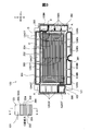
- FIG. 3 is a schematic plan view showing the configuration of the anode separator 120.
- FIG. 3 shows a state as viewed from the surface facing the other unit cell 100 adjacent to the anode separator 120 (hereinafter also referred to as “cooling surface”).
- a surface facing the MEGA 110 opposite to the cooling surface is also referred to as a “gas surface”.
- the anode-side separator 120 is formed by press-molding stainless steel or the like, and sandwiches the MEGA 110 together with the cathode-side separator 130 with an adhesive seal 140 and a gas flow path member 150 interposed therebetween as shown in FIG.
- the fuel gas supply hole 122IN and the fuel gas discharge hole 122OT are individually sealed by the fuel gas sealing material 300, and have a plurality of oxidant gas supply holes 124IN and a plurality of oxidant gas discharge holes 124OT. Is sealed by the oxidant sealing material 301 along the array of holes.
- the cooling water sealing material 302 surrounds the cooling water circulation area including the plurality of cooling water supply holes 126IN, the cooling water discharge holes 126OT, and the separator central area 121 on the cooling surface side, and seals the cooling water circulation area. .
- Such a supply / discharge hole seal is also made in the cathode separator 130.
- the first groove 202 is a concave groove on the gas surface side (first surface) of the anode separator 120 described above, and is concave on the back surface side in FIG. 3, and extends in this gas surface.
- the second groove 204 is a concave groove that is concave on the cooling surface side (second surface) of the anode-side separator 120 described above, and in FIG. Then, the first groove 202 and the second groove 204 are formed as a plurality of concave and convex strips by press molding that presses a concave and convex mold adapted to both groove shapes against the separator central region 121, and in the separator central region 121.
- the anode-side separator 120 is alternately arranged on the front and back surfaces (first surface and second surface). That is, the anode-side separator 120 has a cross-sectional uneven shape (cross-sectional corrugated shape) in which the first grooves 202 and the second grooves 204 are alternately and repeatedly arranged in a longitudinal sectional view in FIG.
- the first groove 202 that is concave on the gas surface side is a fuel gas passage groove that supplies fuel gas to the MEGA 110 exposed to the power generation area window 141 of the adhesive seal 140 (hereinafter also referred to as “fuel gas passage groove 202”).
- fuel gas passage groove 202 constitutes the 1st surface side recessed groove part.
- the second groove 204 that is concave on the cooling surface side constitutes a rib that partitions the fuel gas flow channel groove 202, and the anode side separator 120 comes into contact with the cathode side separator 130 described later, so that the cooling water passes therethrough.
- a cooling water channel groove (hereinafter also referred to as “cooling water channel groove 204”) is formed.
- the plurality of second grooves 204 constitute a second surface side groove portion.
- the fuel gas flow path 200 constituted by the plurality of fuel gas flow path grooves 202 is formed in a serpentine shape from the fuel gas supply hole 122IN to the fuel gas discharge hole 122OT, and the gas surface described above on the back side of the paper in FIG. Formed on the side.
- the unit cell 100 of the present embodiment includes a serpentine-shaped fuel gas flow channel 200 in which a fuel gas flow channel groove 202 positioned on the upper and lower ends of the separator central region 121 shown in FIG.
- the region 121 extends in the left-right direction, that is, the x direction in FIG.
- the first groove 202 functions as a rib that partitions the cooling water flow channel groove 204 on the cooling surface side in the linear flow channel region extending in the x direction including the conversion region A.
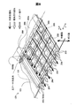
- FIG. 4 is a schematic perspective view showing, in an enlarged manner, the formation state of flow channel grooves in the cooling water supply hole peripheral region B included in the conversion region A shown in FIG.
- the front side of the paper surface is the cooling surface side
- the back surface of the paper surface is the gas surface side.
- Shallow grooves 208 are dotted in the fuel gas flow channel 202 formed along the y direction.
- the shallow groove portion 208 is a portion having a shallower depth than other portions (hereinafter also referred to as “deep groove portion 206”).
- the depth of the fuel gas flow channel 202 means the distance from the position of the portion of the gas surface of the anode separator 120 in contact with the MEGA 110 to the bottom of the fuel gas flow channel 202.
- the depth of the fuel gas flow channel groove 202 is deep at the position of the deep groove portion 206 and becomes shallow at the position of the shallow groove portion 208, the deep groove portion 206 and the shallow groove portion 208 are different in the fuel gas flow in the conversion region A of FIG. Although they are alternately arranged along the groove path of the road groove 202, none of them is in contact with the MEGA 110. Therefore, the fuel gas channel groove 202 allows the fuel gas to pass along the channel groove path also in the conversion region A of FIG. In this case, the depth of the deep groove portion 206 is the same as that of the fuel gas flow path groove 202 in the flow path groove path (fuel gas flow path 200: see FIG. 3) other than the conversion region A.
- the anode separator 120 is formed on the surface of the cathode separator 130 of the adjacent unit cell 100 on the bottom wall of each deep groove 206.
- the outer peripheral surface of 202 s, the ceiling surface in the illustration of FIG. 4, is brought into contact, and the cathode-side separator 130 is not contacted at the position of the shallow groove portion 208.
- communication is established between the surface of the cathode side separator 130 and the two adjacent cooling water passage grooves 204 with the shallow groove portion 208 interposed therebetween.
- a plurality of flow channel grooves 205 are formed.
- This communication channel groove 205 extends from the cooling water supply hole 126IN side and intersects with the cooling water channel groove 204 extending in the y direction.
- the cooling water can flow not only in the y direction along the cooling water channel groove 204 but also in the x direction via the communication channel groove 205. That is, the communication flow channel 205 allows the cooling water to pass through the adjacent cooling water flow channel 204, so that cooling water flows between the adjacent cooling water flow channels 204.
- the cooling water flowing through the cooling water passage groove 204 extending along the x direction is not blocked by the fuel gas passage groove 202 extending along the y direction.
- cooling water flow channel groove 204 extending in the y direction in the cooling water supply hole peripheral region B shown in FIG. 4 eventually extends in the x direction, and in the range extending in the x direction, along the groove path. Pour cooling water.
- shallow grooves 208 are similarly formed in the fuel gas passage grooves 202 along the x direction of the conversion region A shown in FIG. As a result, the flow of the cooling water flowing through the cooling water channel groove 204 parallel to the fuel gas channel groove 202 extending along the y direction is not blocked by the fuel gas channel groove 202 extending along the x direction.
- the fuel gas flow channel groove 202 in which the groove path direction changes obliquely with respect to the x direction and the y direction in the conversion region A is also used.
- the shallow grooves 208 are formed in a dotted manner.
- the cooling water flowing through the cooling water passage groove 204 parallel to the fuel gas passage groove 202 whose groove passage direction extends obliquely with respect to the x direction and the y direction is obliquely extended on both sides of the cooling water passage groove 204.
- the flow is not blocked by the gas flow path groove 202. Therefore, the anode-side separator 120 does not block the cooling water supplied from the cooling water supply hole 126IN by the fuel gas passage groove 202 along either the x direction or the y direction, and the cooling water discharge hole It is possible to flow toward 126 OT.
- the cooling water is changed not only in the cooling water supply hole peripheral region B while changing the flow direction. It flows in the entire area A.
- the anode-side separator 120 is provided with the fuel gas flow channel grooves 202 alternately arranged in the deep groove portions 206 and the shallow groove portions 208 along the groove paths in the conversion region A of FIG.
- the anode-side separator 120 has a linear path in the serpentine-shaped groove path, that is, in the x direction in FIG. 3, other fuel gas flow path grooves 202 including the gas surface side end first grooves 202t, and cooling water
- the cooling water passage groove 204 on the side has a simple concave groove shape.
- the anode-side separator 120 includes a guide projection 127 and a supply hole projection 128.
- the guide convex portion 127 is inclined with respect to the separator central region 121 and protrudes toward the cooling surface between the cooling water supply hole 126IN and the separator central region 121 (see FIG. 3), and has a flat top surface.
- the inter-supply hole convex portion 128 protrudes from the guide convex portion 127 to the cooling surface side in a shape extending between the supply holes, and has a flat top surface.
- the guide convex portion 127 and the supply hole convex portion 128 protrude toward the cooling surface such that the top surface has the same height as the bottom wall 202 s of the deep groove portion 206.
- the guide convex portion 127 and the inter-supply-hole convex portion 128 have their top surfaces in close contact with the cathode-side separator 130 and between the separators.
- a cooling water circulation region is formed, and a rectifying function for introducing the cooling water into the cooling water channel groove 204 and the communication channel groove 205 is exhibited while guiding the cooling water from the cooling water supply hole 126IN.
- FIG. 5 is an explanatory diagram showing, in plan view, from the cooling surface side, the state of formation of flow channel grooves in the fuel gas supply hole peripheral region D included in the conversion region A shown in FIG. Also in FIG. 5, the front side of the paper surface is the cooling surface side, and the back surface of the paper surface is the gas surface side.
- the introduction flow path section 230 is a flow path area connected to the fuel gas supply hole 122IN, and the connection flow path section 220 internally flows the fuel gas flowing from the fuel gas supply hole 122IN via the introduction flow path section 230. As shown in the figure, it is a flow passage area that is transferred to each gas flow passage of the passage portion 210, is inclined after extending in the x direction, and again extends in the x direction.
- the connecting channel portion 220 includes a first connecting channel portion 200b extending in the x direction so as to be connected to the fuel gas channel portion 200a including the fuel gas channel groove 202 belonging to the inner channel portion 210, and the first connecting channel portion 220b.
- the first connection channel portion 200b is composed of a plurality of first connection channel grooves 202b that are connected to the plurality of fuel gas channel grooves 202a of the fuel gas channel portion 200a and extend in the x direction.
- the second connection channel portion 200c includes a plurality of second connection channel grooves 202c (hereinafter, inclined gas channel grooves 202c) extending downward from the first connection channel groove 202b along a direction inclined in the gravitational direction. Also called).
- the second connection channel groove 202c preferably extends downward along a direction inclined with respect to the direction of gravity (for example, obliquely downward), but may extend in the direction of gravity.
- the third connection channel portion 200d is composed of a plurality of third connection channel grooves 202d that are connected to the boundary channel groove 202e and the second connection channel groove 202c and extend in the x direction.
- the boundary flow path groove 202e is configured by a groove extending along the y direction at the boundary between the third connection flow path portion 200d and the introduction flow path portion 230.
- each connection channel groove 202b, 202c, 202d which comprises the connection channel part 220 is made into the deep groove part 206 and the shallow groove part 208 along each groove path
- the communication flow channel grooves corresponding to the communication flow channel grooves 205 in FIG. 4 are provided in the adjacent cooling water flow channel grooves 204 so that the cooling water flows on the cooling surface side.
- the introduction flow path section 230 includes a first introduction flow path portion 230A connected to the boundary flow groove 202e, and a second introduction flow path portion 230B connected to the first introduction flow path portion 230A and the fuel gas supply hole 122IN. Yes.
- These introduction flow path portions 230 ⁇ / b> A and 230 ⁇ / b> B are formed between the sealing plate 129 disposed between the gas surface of the anode side separator 120 and the anode side separator 120.
- the first introduction flow path portion 230A is connected to the boundary flow path groove 202e and includes a plurality of first lead-out flow path grooves 232A constituting a substantially comb-shaped flow path.
- the second introduction channel portion 230B is formed by a substantially comb-like convex portion 234B formed on the sealing plate 129, and constitutes a substantially comb-like channel.
- the outlet side region connected to the fuel gas discharge hole 122OT in the fuel gas channel 200 is similar to the above-described inlet side region, and the introduction channel portion connected to the fuel gas discharge hole 122OT, And it is comprised by the connection flow path part between an introductory flow path part and an internal flow path part.
- the cooling water flow channel 204 is formed between the fuel gas flow channel portions 200a to 202d described above, and in the formation region of the second connection flow channel groove 202c, the cooling water flow that is apparently blocked in the groove channel direction.
- a road groove 204 is formed.
- the communication channel grooves 205 that allow the passage of the cooling water are the deep groove portions 206 and the shallow groove portions 208 in the respective fuel gas channel grooves 202. Therefore, the cooling water flows between the adjacent cooling water flow channel grooves 204, so that the cooling water also enters the cooling water flow channel grooves 204 closed in the direction of the groove path, along the cooling water flow channel grooves. Flowing.
- the anode-side separator 120 of the present embodiment has the groove shape described with reference to FIGS. 4 to 5 in the conversion regions A at the left and right ends of the separator central region 121 shown in FIG.
- the cooling water is passed through the discharge hole 126OT as follows.
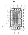
- FIG. 6 is an explanatory diagram schematically showing the flow of cooling water on the cooling surface side in the anode-side separator 120.
- the cooling water supplied from each supply hole of the cooling water supply hole 126IN enters the cooling water flow path groove 204 in the conversion area A on the supply hole side via the communication flow path groove 205.
- the flow of the cooling water at this time undergoes rectification at the guide convex portion 127 and the convex portion 128 between the supply holes (see FIG. 4), so the cooling water supply hole located on the lower right side of the anode side separator 120 in the drawing.
- the flow is generally obliquely upward from 126IN.
- the anode-side separator 120 causes the above-described flow of the cooling water through the communication flow channel 205 as a result of the interspersed arrangement of the deep grooves 206 and the shallow grooves 208.
- the anode-side separator 120 uses fuel to introduce cooling water from the cooling water supply holes 126IN into the respective cooling water passage grooves 204 extending horizontally across the vertical direction of the separator central region 121 (see FIG. 3).
- the cooling water for the outer edge 123 is formed by the guide protrusion 127, the supply hole protrusion 128, and the deep grooves 206 and the shallow grooves 208 that are interspersed in the fuel gas passage groove 202.
- the cooling water supplied from the supply holes 126IN is diffused and introduced into the grooves of the respective cooling water passage grooves 204 while changing the flow direction.
- the corner portion on the fuel gas supply hole 122IN side of the separator central region 121 that is, on the upper end side of the separator central region 121 and around the separator central region corner portion on the cooling water supply hole 126IN side, The flow of the cooling water toward the upper end side of the central region 121 occurs.
- each fuel gas channel groove 202 constituting the channel extends along the horizontal direction (x direction) in the figure. . Therefore, the cooling water turned in the horizontal direction in the conversion area A flows in the horizontal direction along the fuel gas passage groove 202.
- the flow direction of the cooling water as a whole is a direction from the horizontal direction toward each cooling water discharge hole 126OT by the communication flow path groove 205 described above.
- the anode separator 120 rectifies the cooling water between the guide protrusion 127 and the supply hole-to-supply hole protrusion 128 (see FIG. 4), while cooling the cooling water from the groove of the cooling water passage groove 204 to the fuel gas discharge hole 122OT. Lead.
- FIG. 7 is an explanatory diagram showing the flow channel groove formation state in the corner portion DC of the separator central region 121 on the fuel gas supply hole 122IN side shown in FIG. It is a schematic perspective view which expands and shows the formation condition of the flow-path groove
- the gas surface side end first groove 202t allows the fuel gas to pass in the x direction along the flow path groove path. .
- the anode-side separator 120 does not contact the outer peripheral surface of the depression corner recess 202tb, and the ceiling surface in the illustration of FIG. Therefore, the depression corner recess 202tb communicates the cooling water passage groove 204 extending in the x direction below the end first groove 202t and the outer edge 123 above the end first groove 202t in FIG. Thereby, the cooling water that has flown into the cooling water flow path groove 204 below the first end groove 202t can pass through the depression corner recess 202tb to the outer edge 123 side of the outer edge of the separator central region 121. .
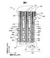
- FIG. 9 is a schematic cross-sectional view of the fuel cell 10 taken along line 9-9 at an enlarged portion of the portion C in FIG.
- the fuel cell 10 is configured by stacking a plurality of unit cells 100, and the unit cell 100 sandwiches the MEGA 110 between an anode-side separator 120 and a cathode-side separator 130.
- the MEGA 110 is shown in a form in which an MEA 110D having a catalyst electrode layer bonded to both membrane surfaces of the electrolyte membrane is sandwiched between the anode-side gas diffusion layer 110A and the cathode-side gas diffusion layer 110C.
- Each unit cell 100 includes an outer edge portion 123 (see FIGS. 2 to 3) that the anode-side separator 120 extends to the outside of the separator central region 121, and a power generation region 112 (see FIGS. 2 to 3) of the MEGA 110.
- each unit cell 100 is joined with the separator central region 121 in which the first groove 202 and the second groove 204 are formed facing the power generation region 112 of the MEGA 110.
- the end first groove 202t and the first groove 202 in another part function as the fuel gas flow channel 202 extending as described above, with the concave groove opening end closed by the MEGA 110.
- the bottom wall 202 s of the first groove 202 included in the anode-side separator 120 of one unit cell 100 is brought into contact with the cathode-side separator 130 of the other unit cell 100.
- the second groove 204 functions as the cooling water channel groove 204 that extends as described above, with the concave groove opening end closed.
- the legs 131 included in the cathode separator 130 of one unit cell 100 are brought into contact with the outer edge 123 of the anode separator 120 of the other unit cell 100. Accordingly, the legs 131 function as supports for the unit cells 100 at the outer edge portion 123 of the anode separator 120.
- the unit cells 100 stacked adjacent to each other have a coolant flow including a separator central region 121 and a fuel gas discharge hole 122OT on the cooling surface side where the fuel gas supply hole 122IN and the coolant flow channel 204 are opened.
- the cooling water sealing material 302 (see FIG. 3) surrounding the area and the oxidant sealing material 301 surrounding the oxidant gas discharge hole 124OT are connected to the anode side separator 120 of one unit cell 100 and the other at the upper end side of the separator.
- the unit cell 100 is sandwiched between the cathode side separator 130.
- the cooling water sealing material 302 and the oxidizing gas sealing material 301 surrounding the oxidizing gas supply hole 124IN are provided at the lower end of the separator, and the cooling water sealing material 302 and the fuel gas supply hole 122IN are provided at the left and right ends of the separator.
- the fuel gas sealing material 300 surrounding the fuel gas and the fuel gas sealing material 300 surrounding the fuel gas discharge hole 122OT are sandwiched between the anode separator 120 of one unit cell 100 and the cathode separator 130 of the other unit cell 100.
- the fuel cell 10 in which the unit cells 100 are stacked in this way is fastened in the cell stacking direction by a fastening shaft or the like (not shown).
- the fuel cell 10 of this embodiment is subjected to an air discharge treatment from the cooling water flow channel 204 of the anode-side separator 120 in each unit cell 100 at the time of completion of stacking and stacking and fastening shown in FIG. That is, in the anode separator 120, the cooling water is supplied from the cooling water supply hole 126IN.
- the cooling water supplied in this way reaches the conversion area A occupied by the cooling water supply hole 126IN in the separator central area 121, and then between the adjacent cooling water flow path grooves 204 by the communication flow path grooves 205 in the area.
- the cooling water passes, the cooling water flows into the respective cooling water channel grooves 204 from the cooling water supply holes 126IN.
- the cooling water reaches the entire conversion area A on the fuel gas supply hole 122IN side. Therefore, according to the fuel cell 10 of the present embodiment, the fuel gas supplied with the power generation operation is not consumed yet. Thus, the region around the fuel gas supply hole 122IN, which tends to have an active power generation reaction, can be cooled with high efficiency.
- the cooling water that has entered the cooling water flow channel groove 204 pushes the air in the groove while flowing in the cooling water flow channel groove 204 along the groove path if air remains in the groove. Then, as described in FIG. 6, the flow of the cooling water in the conversion area A is horizontally directed from the direction directed obliquely upward as the flow direction from the cooling water supply hole 126IN toward the cooling water discharge hole 126OT. Converted to direction.
- the cooling water flows through the cooling water channel groove 204 and the communication channel groove 205 in the conversion area A, the cooling water flows even if it is in the air in these grooves, but the cooling water flows as described above. Since it passes while changing the direction of the stagnation, stagnation can occur in the flow of the cooling water.
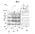
- FIG. 10 is an explanatory view showing the flow channel groove formation state in the corner portion DC of the separator central region 121 in the proportional anode side separator 120H further enlarged in plan view from the cooling surface side.
- the first groove 202t at the upper end of the separator central region 121 has a simple groove shape that does not include the recessed corner recess 202tb. Then, the cooling water flow path groove 204 extending below the end first groove 202t is closed by contact with the cathode separator 130, so that the air in the groove rising to the end first groove 202t side is Further, it is assumed that the end first groove 202t prevents further rise and forms an air pool on the end side of the end first groove 202t. This air pool covers the peripheral region of the fuel gas supply hole 122IN where the fuel gas reaches the first state without being consumed and the power generation reaction tends to be active.
- the anode-side separator 120 of the present embodiment has a depressed corner recess 202tb in the first end groove 202t.
- the depression corner recess 202tb communicates the cooling water passage groove 204 extending in the x direction below the end first groove 202t and the outer edge 123 above the end first groove 202t.
- the air in the groove rising to the groove 202t side passes through the depression corner recess 202tb together with the cooling water rising to the end first groove 202t side, and is discharged from the separator central region 121 to the outer edge 123 of the outer edge. Is done.
- each unit cell can be achieved with high cooling efficiency. 100 can be cooled.
- the air thus discharged to the outer edge portion 123 passes between the outer edge portion 123 and the cathode separator 130 (see FIG. 9) and is taken out of the unit cell from the cooling water discharge hole 126OT.
- an air pool in the cooling water channel groove 204 is avoided in the peripheral region of the fuel gas supply hole 122IN where the fuel gas reaches the first state without being consumed and the power generation reaction tends to be active.
- the cooling effect can be maintained, or a factory can be established.
- the depressed corner recess 202tb with the bottom wall depressed is formed at the end portion from the fuel gas supply hole 122IN side of the first end groove 202t, the air reservoir The avoidance configuration can be simplified and air accumulation can be easily avoided.
- the depression corner recess 202tb is formed in the end first groove 202t by press molding of the second gas groove 204 including the end first groove 202t and the fuel gas passage groove 202, so that the separator Manufacturing cost can be reduced.
- the depression corner recess 202tb has a shallower groove depth than the other groove path portions of the end first groove 202t, so that the press male mold used to mold the uniform groove-shaped end first groove 202t is used. It is sufficient to polish the top of the ridge using a precision grinding wheel machine. Also from this point, according to the anode-side separator 120 of the present embodiment, the separator manufacturing cost can be reduced, and the avoidance of air accumulation can be eliminated or suppressed by a simple technique of polishing the top of the protruding male die. In addition, since the top of the ridges of the existing press male mold can be polished, the existing equipment can be used effectively, and the cost for manufacturing the separator can be further reduced due to the reduction in the mold cost.
- the deep groove portion 206 is formed in the groove path of the fuel gas passage groove 202.
- shallow groove portions 208 are formed in a dotted manner.
- the shallow groove portion 208 only needs to be shallower than the deep groove portion 206, and is formed by press molding in the same manner as the depressed corner recess 202tb described above. Therefore, also from this point, according to the anode-side separator 120 of this embodiment, the separator manufacturing cost can be reduced.
- the fuel cell 10 of the present embodiment uses the anode-side separator 120 that avoids air accumulation at the recessed corner recess 202tb of the corner portion DC (see FIG. 5) of the separator central region 121. Therefore, according to the fuel cell 10 of the present embodiment, insufficient cooling during the power generation operation is not caused, so that the battery performance can be maintained or improved.
- the anode-side separator 120 having the recessed corner recess 202tb in the first end groove 202t extending at the upper end of the separator central region 121 may be replaced with the existing unit cell 100. Therefore, according to the fuel cell 10 of the present embodiment, it is possible to reduce the battery manufacturing cost, and it is possible to easily eliminate or suppress problems such as insufficient cooling that may occur due to air accumulation.
- each unit cell 100 has only one depression corner recess 202tb in the corner portion DC on the fuel gas supply hole 122IN side of the separator central region 121. Therefore, the cooling water is not carelessly poured out from the separator central region 121 to the outer edge portion 123 of the outer edge through the depressed corner recess 202tb, so that insufficient cooling in the separator central region 121 is not caused.
- the present invention is not limited to the above-described embodiment, and can be realized with various configurations without departing from the spirit of the present invention.
- the technical features of the embodiments corresponding to the technical features in each embodiment described in the summary section of the invention are intended to solve part or all of the above-described problems, or part of the above-described effects. Or, in order to achieve the whole, it is possible to replace or combine as appropriate. Further, if the technical feature is not described as essential in the present specification, it can be deleted as appropriate.
- the corner portion DC (see FIG. 5) of the separator central region 121 is provided with the depressed corner recess 202tb in the end first groove 202t. If an air pool can be generated in another part by the groove path of the cooling water flow path groove 204, the depressed corner recess 202tb may be provided in the part. The location where the air accumulation may occur may be specified by an experimental method using the unit cell 100 itself in addition to a simulation using a computer.
- a recessed corner recess 202tb similar to that on the fuel gas supply hole 122IN side may be provided in the corner portion of the separator central region 121 on the cooling water discharge hole 126OT side.
- the recessed corner recesses 202tb may be provided at a plurality of locations of the end first groove 202t extending at the upper end of the separator central region 121.
- the cooling water flows from the cooling water supply hole 126IN on the right side in the drawing of the anode separator 120 toward the cooling water discharge hole 126OT facing the separator central region 121.
- the cooling water discharge hole 126OT in FIG. 6 may be used as the cooling water supply hole 126IN
- the cooling water discharge hole 126OT in FIG. 6 may be used as the cooling water supply hole 126IN.
- the depressed corner recess 202tb may be provided in the end first groove 202t in the corner portion of the separator central region 121 on the left end side in FIG.
- a recess 202tb may be provided.
- the fuel gas channel groove 202 and the cooling water channel groove 204 are formed by press molding. However, the fuel gas channel groove 202 and the cooling water channel groove 204 are provided on the front and back surfaces of the separator by cutting or the like. You may do it.
Landscapes
- Life Sciences & Earth Sciences (AREA)
- Engineering & Computer Science (AREA)
- Manufacturing & Machinery (AREA)
- Sustainable Development (AREA)
- Sustainable Energy (AREA)
- Chemical & Material Sciences (AREA)
- Chemical Kinetics & Catalysis (AREA)
- Electrochemistry (AREA)
- General Chemical & Material Sciences (AREA)
- Fuel Cell (AREA)
Priority Applications (4)
| Application Number | Priority Date | Filing Date | Title |
|---|---|---|---|
| CN201480054328.XA CN105637689B (zh) | 2013-10-02 | 2014-09-30 | 燃料电池用分隔件和燃料电池 |
| KR1020167008410A KR101885972B1 (ko) | 2013-10-02 | 2014-09-30 | 연료 전지용 세퍼레이터 및 연료 전지 |
| DE112014004569.1T DE112014004569B4 (de) | 2013-10-02 | 2014-09-30 | Brennstoffzellenseparator und Brennstoffzelle |
| US15/023,825 US10468690B2 (en) | 2013-10-02 | 2014-09-30 | Fuel cell separator and fuel cell |
Applications Claiming Priority (2)
| Application Number | Priority Date | Filing Date | Title |
|---|---|---|---|
| JP2013207008A JP5942955B2 (ja) | 2013-10-02 | 2013-10-02 | 燃料電池用セパレーターと燃料電池 |
| JP2013-207008 | 2013-10-02 |
Publications (1)
| Publication Number | Publication Date |
|---|---|
| WO2015049860A1 true WO2015049860A1 (ja) | 2015-04-09 |
Family
ID=52778465
Family Applications (1)
| Application Number | Title | Priority Date | Filing Date |
|---|---|---|---|
| PCT/JP2014/004992 Ceased WO2015049860A1 (ja) | 2013-10-02 | 2014-09-30 | 燃料電池用セパレーターおよび燃料電池 |
Country Status (6)
| Country | Link |
|---|---|
| US (1) | US10468690B2 (enExample) |
| JP (1) | JP5942955B2 (enExample) |
| KR (1) | KR101885972B1 (enExample) |
| CN (1) | CN105637689B (enExample) |
| DE (1) | DE112014004569B4 (enExample) |
| WO (1) | WO2015049860A1 (enExample) |
Cited By (1)
| Publication number | Priority date | Publication date | Assignee | Title |
|---|---|---|---|---|
| CN114556643A (zh) * | 2019-10-16 | 2022-05-27 | 株式会社捷太格特 | 燃料电池 |
Families Citing this family (7)
| Publication number | Priority date | Publication date | Assignee | Title |
|---|---|---|---|---|
| KR101990281B1 (ko) | 2015-06-30 | 2019-06-18 | 주식회사 엘지화학 | 분리판, 이의 제조방법 및 이를 포함하는 연료전지 스택 |
| CN107952879A (zh) * | 2016-10-18 | 2018-04-24 | 标致雪铁龙集团 | 一种汽车顶棚成型模具总成 |
| JP7040131B2 (ja) * | 2018-03-02 | 2022-03-23 | トヨタ自動車株式会社 | セパレータの製造方法 |
| CN109921057A (zh) * | 2019-04-04 | 2019-06-21 | 浙江大学 | 一种波纹交错排布的燃料电池双极板结构 |
| JP7192759B2 (ja) * | 2019-12-24 | 2022-12-20 | トヨタ車体株式会社 | 燃料電池用セパレータ |
| CN112421068B (zh) * | 2020-10-19 | 2021-11-30 | 国科微城市智能科技(南京)有限责任公司 | 一种氢燃料电池用制造的设备及操作方法 |
| KR102550727B1 (ko) | 2021-04-16 | 2023-07-04 | 현대모비스 주식회사 | 연료전지용 분리판 및 연료전지 스택 |
Citations (2)
| Publication number | Priority date | Publication date | Assignee | Title |
|---|---|---|---|---|
| JP2004193110A (ja) * | 2002-11-26 | 2004-07-08 | Honda Motor Co Ltd | 燃料電池 |
| WO2012160607A1 (ja) * | 2011-05-26 | 2012-11-29 | トヨタ自動車株式会社 | 燃料電池用セパレータおよび燃料電池 |
Family Cites Families (9)
| Publication number | Priority date | Publication date | Assignee | Title |
|---|---|---|---|---|
| JP4019554B2 (ja) | 1998-08-03 | 2007-12-12 | トヨタ自動車株式会社 | 燃料電池セパレータ用多連凹凸板の製造方法 |
| US6613470B1 (en) * | 1999-09-01 | 2003-09-02 | Honda Giken Kogyo Kabushiki Kaisha | Solid polymer electrolyte fuel cell stack |
| JP2006216350A (ja) * | 2005-02-03 | 2006-08-17 | Nissan Motor Co Ltd | 燃料電池システム |
| JP4791152B2 (ja) | 2005-11-11 | 2011-10-12 | 本田技研工業株式会社 | 燃料電池スタック |
| EP2131430B1 (en) * | 2007-03-15 | 2013-04-17 | Panasonic Corporation | Polymer electrolyte fuel cell and fuel cell stack having the same |
| JP5562593B2 (ja) | 2009-06-04 | 2014-07-30 | 本田技研工業株式会社 | 燃料電池スタック |
| CN101572318B (zh) * | 2009-06-16 | 2010-12-08 | 新源动力股份有限公司 | 一种质子交换膜燃料电池金属双极板 |
| WO2012035585A1 (ja) | 2010-09-16 | 2012-03-22 | トヨタ自動車株式会社 | 燃料電池用セパレータ、燃料電池、燃料電池の製造方法 |
| JP5624516B2 (ja) | 2011-06-08 | 2014-11-12 | 株式会社東芝 | 燃料電池及び燃料電池用セパレータ |
-
2013
- 2013-10-02 JP JP2013207008A patent/JP5942955B2/ja active Active
-
2014
- 2014-09-30 KR KR1020167008410A patent/KR101885972B1/ko active Active
- 2014-09-30 CN CN201480054328.XA patent/CN105637689B/zh active Active
- 2014-09-30 WO PCT/JP2014/004992 patent/WO2015049860A1/ja not_active Ceased
- 2014-09-30 DE DE112014004569.1T patent/DE112014004569B4/de active Active
- 2014-09-30 US US15/023,825 patent/US10468690B2/en active Active
Patent Citations (2)
| Publication number | Priority date | Publication date | Assignee | Title |
|---|---|---|---|---|
| JP2004193110A (ja) * | 2002-11-26 | 2004-07-08 | Honda Motor Co Ltd | 燃料電池 |
| WO2012160607A1 (ja) * | 2011-05-26 | 2012-11-29 | トヨタ自動車株式会社 | 燃料電池用セパレータおよび燃料電池 |
Cited By (1)
| Publication number | Priority date | Publication date | Assignee | Title |
|---|---|---|---|---|
| CN114556643A (zh) * | 2019-10-16 | 2022-05-27 | 株式会社捷太格特 | 燃料电池 |
Also Published As
| Publication number | Publication date |
|---|---|
| KR101885972B1 (ko) | 2018-08-06 |
| CN105637689A (zh) | 2016-06-01 |
| DE112014004569B4 (de) | 2020-08-06 |
| JP5942955B2 (ja) | 2016-06-29 |
| JP2015072755A (ja) | 2015-04-16 |
| KR20160050055A (ko) | 2016-05-10 |
| CN105637689B (zh) | 2017-10-13 |
| US20160248104A1 (en) | 2016-08-25 |
| DE112014004569T5 (de) | 2016-07-07 |
| US10468690B2 (en) | 2019-11-05 |
Similar Documents
| Publication | Publication Date | Title |
|---|---|---|
| JP5942955B2 (ja) | 燃料電池用セパレーターと燃料電池 | |
| CA2644787C (en) | Fuel cell having porous body and reaction gas leakage prevention section, and method for producing the same | |
| CN110197913B (zh) | 发电单电池 | |
| JP2008293790A (ja) | 燃料電池 | |
| JP2011014530A (ja) | 燃料電池スタック | |
| US20150236368A1 (en) | Gas flow path forming bodies of fuel cell, and fuel cell | |
| JP5139753B2 (ja) | 燃料電池 | |
| US9806360B2 (en) | Unit cell for solid-oxide fuel cell and solid-oxide fuel cell using same | |
| CN105594036B (zh) | 分隔件及燃料电池 | |
| JP2016146313A (ja) | バイポーラプレート及びダイレクトメタノール型燃料電池 | |
| JP6090091B2 (ja) | 燃料電池 | |
| JP5234446B2 (ja) | 燃料電池スタック用金属セパレータの積層性向上構造 | |
| CA2602153C (en) | Fuel cell and fuel cell separator having a cooling medium regulating portion | |
| JP6053649B2 (ja) | 燃料電池 | |
| JP2007134206A (ja) | 燃料電池スタック | |
| JP5338512B2 (ja) | 燃料電池用ガスケット、燃料電池用積層部材、および燃料電池 | |
| JP2006147258A (ja) | セパレータ及び燃料電池スタック | |
| KR101313382B1 (ko) | 냉각수 흐름을 개선한 연료전지용 금속 분리판 및 이를 구비하는 연료전지 스택 | |
| JP2005267868A (ja) | 燃料電池 | |
| JP2011171115A (ja) | 燃料電池 | |
| JP2008293694A (ja) | 燃料電池 | |
| JP5583824B2 (ja) | 燃料電池 | |
| JP2008123751A (ja) | 燃料電池 | |
| JP5423699B2 (ja) | ガス流路形成体および燃料電池セル | |
| JP5886739B2 (ja) | 燃料電池スタック |
Legal Events
| Date | Code | Title | Description |
|---|---|---|---|
| 121 | Ep: the epo has been informed by wipo that ep was designated in this application |
Ref document number: 14850607 Country of ref document: EP Kind code of ref document: A1 |
|
| WWE | Wipo information: entry into national phase |
Ref document number: 15023825 Country of ref document: US |
|
| ENP | Entry into the national phase |
Ref document number: 20167008410 Country of ref document: KR Kind code of ref document: A |
|
| WWE | Wipo information: entry into national phase |
Ref document number: 112014004569 Country of ref document: DE Ref document number: 1120140045691 Country of ref document: DE |
|
| 122 | Ep: pct application non-entry in european phase |
Ref document number: 14850607 Country of ref document: EP Kind code of ref document: A1 |