WO2015045875A1 - 硫化物固体電解質材料、電池および硫化物固体電解質材料の製造方法 - Google Patents
硫化物固体電解質材料、電池および硫化物固体電解質材料の製造方法 Download PDFInfo
- Publication number
- WO2015045875A1 WO2015045875A1 PCT/JP2014/073952 JP2014073952W WO2015045875A1 WO 2015045875 A1 WO2015045875 A1 WO 2015045875A1 JP 2014073952 W JP2014073952 W JP 2014073952W WO 2015045875 A1 WO2015045875 A1 WO 2015045875A1
- Authority
- WO
- WIPO (PCT)
- Prior art keywords
- solid electrolyte
- sulfide solid
- electrolyte material
- electrode active
- active material
- Prior art date
- Legal status (The legal status is an assumption and is not a legal conclusion. Google has not performed a legal analysis and makes no representation as to the accuracy of the status listed.)
- Ceased
Links
Images





Classifications
-
- H—ELECTRICITY
- H01—ELECTRIC ELEMENTS
- H01M—PROCESSES OR MEANS, e.g. BATTERIES, FOR THE DIRECT CONVERSION OF CHEMICAL ENERGY INTO ELECTRICAL ENERGY
- H01M10/00—Secondary cells; Manufacture thereof
- H01M10/05—Accumulators with non-aqueous electrolyte
- H01M10/056—Accumulators with non-aqueous electrolyte characterised by the materials used as electrolytes, e.g. mixed inorganic/organic electrolytes
- H01M10/0561—Accumulators with non-aqueous electrolyte characterised by the materials used as electrolytes, e.g. mixed inorganic/organic electrolytes the electrolyte being constituted of inorganic materials only
- H01M10/0562—Solid materials
-
- C—CHEMISTRY; METALLURGY
- C01—INORGANIC CHEMISTRY
- C01B—NON-METALLIC ELEMENTS; COMPOUNDS THEREOF; METALLOIDS OR COMPOUNDS THEREOF NOT COVERED BY SUBCLASS C01C
- C01B17/00—Sulfur; Compounds thereof
- C01B17/22—Alkali metal sulfides or polysulfides
-
- H—ELECTRICITY
- H01—ELECTRIC ELEMENTS
- H01B—CABLES; CONDUCTORS; INSULATORS; SELECTION OF MATERIALS FOR THEIR CONDUCTIVE, INSULATING OR DIELECTRIC PROPERTIES
- H01B1/00—Conductors or conductive bodies characterised by the conductive materials; Selection of materials as conductors
- H01B1/06—Conductors or conductive bodies characterised by the conductive materials; Selection of materials as conductors mainly consisting of other non-metallic substances
- H01B1/10—Conductors or conductive bodies characterised by the conductive materials; Selection of materials as conductors mainly consisting of other non-metallic substances sulfides
-
- H—ELECTRICITY
- H01—ELECTRIC ELEMENTS
- H01M—PROCESSES OR MEANS, e.g. BATTERIES, FOR THE DIRECT CONVERSION OF CHEMICAL ENERGY INTO ELECTRICAL ENERGY
- H01M10/00—Secondary cells; Manufacture thereof
- H01M10/05—Accumulators with non-aqueous electrolyte
- H01M10/052—Li-accumulators
-
- H—ELECTRICITY
- H01—ELECTRIC ELEMENTS
- H01M—PROCESSES OR MEANS, e.g. BATTERIES, FOR THE DIRECT CONVERSION OF CHEMICAL ENERGY INTO ELECTRICAL ENERGY
- H01M2300/00—Electrolytes
- H01M2300/0017—Non-aqueous electrolytes
- H01M2300/0065—Solid electrolytes
-
- H—ELECTRICITY
- H01—ELECTRIC ELEMENTS
- H01M—PROCESSES OR MEANS, e.g. BATTERIES, FOR THE DIRECT CONVERSION OF CHEMICAL ENERGY INTO ELECTRICAL ENERGY
- H01M2300/00—Electrolytes
- H01M2300/0017—Non-aqueous electrolytes
- H01M2300/0065—Solid electrolytes
- H01M2300/0068—Solid electrolytes inorganic
-
- Y—GENERAL TAGGING OF NEW TECHNOLOGICAL DEVELOPMENTS; GENERAL TAGGING OF CROSS-SECTIONAL TECHNOLOGIES SPANNING OVER SEVERAL SECTIONS OF THE IPC; TECHNICAL SUBJECTS COVERED BY FORMER USPC CROSS-REFERENCE ART COLLECTIONS [XRACs] AND DIGESTS
- Y02—TECHNOLOGIES OR APPLICATIONS FOR MITIGATION OR ADAPTATION AGAINST CLIMATE CHANGE
- Y02E—REDUCTION OF GREENHOUSE GAS [GHG] EMISSIONS, RELATED TO ENERGY GENERATION, TRANSMISSION OR DISTRIBUTION
- Y02E60/00—Enabling technologies; Technologies with a potential or indirect contribution to GHG emissions mitigation
- Y02E60/10—Energy storage using batteries
-
- Y—GENERAL TAGGING OF NEW TECHNOLOGICAL DEVELOPMENTS; GENERAL TAGGING OF CROSS-SECTIONAL TECHNOLOGIES SPANNING OVER SEVERAL SECTIONS OF THE IPC; TECHNICAL SUBJECTS COVERED BY FORMER USPC CROSS-REFERENCE ART COLLECTIONS [XRACs] AND DIGESTS
- Y02—TECHNOLOGIES OR APPLICATIONS FOR MITIGATION OR ADAPTATION AGAINST CLIMATE CHANGE
- Y02T—CLIMATE CHANGE MITIGATION TECHNOLOGIES RELATED TO TRANSPORTATION
- Y02T10/00—Road transport of goods or passengers
- Y02T10/60—Other road transportation technologies with climate change mitigation effect
- Y02T10/70—Energy storage systems for electromobility, e.g. batteries
Definitions
- the present invention relates to a sulfide solid electrolyte material having good reduction resistance.
- lithium batteries currently on the market use an electrolyte containing a flammable organic solvent, it is possible to install safety devices that suppress the temperature rise during short circuits and to improve the structure and materials to prevent short circuits. Necessary.
- a lithium battery in which the electrolyte is changed to a solid electrolyte layer to make the battery completely solid does not use a flammable organic solvent in the battery, so the safety device can be simplified, and manufacturing costs and productivity can be reduced. It is considered excellent.
- Patent Document 1 discloses a Li ion conductor (sulfide solid electrolyte material) having a composition of Li (4-x) Ge (1-x) P x S 4 .
- the LiGePS-based sulfide solid electrolyte material described in Patent Document 1 has a problem of low reduction resistance.
- the present invention has been made in view of the above problems, and has as its main object to provide a sulfide solid electrolyte material having good reduction resistance.
- Li element, Me element is selected from the group consisting of Sb, Si, Ge, Sn, B, Al, Ga, In, Ti, Zr, V, and Nb.
- a plurality of the first structures comprising a second structure composed of a second ion conductor containing the Li element, the Me element, the P element, and the S element.
- a sulfide solid electrolyte material characterized in that the weight ratio ⁇ of the Me element to the P element is less than 0.72 in the second structure part.
- the second structure portion is formed so as to cover the first structure portion, and the weight ratio ⁇ in the second structure portion is small, a sulfide solid electrolyte material having good reduction resistance is obtained. be able to.
- the second structure part is formed so as to cover the first structure part, and the content of the Me element in the second structure part is less than the content of the Me element in the first structure part.
- a sulfide solid electrolyte material having good reduction resistance can be obtained.
- at least one of the positive electrode active material layer, the negative electrode active material layer, and the electrolyte layer contains the sulfide solid electrolyte material described above.
- a battery having good reduction resistance can be obtained by using the above-described sulfide solid electrolyte material.
- a method for producing the sulfide solid electrolyte material described above wherein the ionized by mechanical milling using the raw material composition containing the components of the sulfide solid electrolyte material.
- a method for producing a sulfide solid electrolyte material comprising: an ion conductive material synthesis step for synthesizing a conductive material; and a heating and quenching step for heating and quenching the amorphous ion conductive material. provide.
- a sulfide solid electrolyte material having good reduction resistance can be obtained by synthesizing an ion conductive material made amorphous by mechanical milling and then heating and quenching.
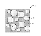
- FIG. 1 It is a schematic sectional drawing which shows an example of the sulfide solid electrolyte material of this invention.
- 2 is a perspective view illustrating an example of a crystal structure of a crystal phase A.
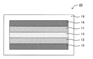
- FIG. It is a schematic sectional drawing which shows an example of the battery of this invention. It is explanatory drawing which shows an example of the manufacturing method of the sulfide solid electrolyte material of this invention. It is a result of the XRD measurement of the sulfide solid electrolyte material obtained in Example 1 and Comparative Examples 1 and 2.
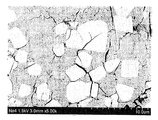
- 3 is a result of SEM measurement of the sulfide solid electrolyte material obtained in Example 1.
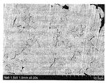
- 4 is a result of SEM measurement of the sulfide solid electrolyte material obtained in Comparative Example 1.
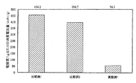
- 4 is a result of SEM measurement of the sulfide solid electrolyte material obtained in Comparative Example 2. It is a result of the reduction resistance evaluation of the sulfide solid electrolyte material obtained in Example 1 and Comparative Examples 1 and 2. It is a result of the reduction resistance evaluation of the sulfide solid electrolyte material obtained in Example 1 and Comparative Examples 1 and 2.
- the sulfide solid electrolyte material of the present invention will be described.
- the sulfide solid electrolyte material of the present invention can be roughly divided into two embodiments. Therefore, the sulfide solid electrolyte material of the present invention will be described separately for the first embodiment and the second embodiment.
- FIG. 1 is a schematic cross-sectional view showing an example of a sulfide solid electrolyte material of a first embodiment.
- a sulfide solid electrolyte material 10 in FIG. 1 includes a first structure portion 1 composed of a first ion conductor containing a Li element, a Me element, a P element and a S element, a Li element, a Me element, a P element, and And a second structure portion 2 composed of a second ion conductor containing an S element. Further, a second structure portion 2 is formed so as to cover the plurality of first structure portions 1. In other words, the second structure portion 2 is formed so as to fill a space between the plurality of first structure portions 1.
- the 1st ion conductor which comprises the 1st structure part 1 has a specific peak in X-ray-diffraction measurement, and has high ionic conductivity. Further, in the second structure part 2, the weight ratio ⁇ of the Me element to the P element is sufficiently small.
- the second structure portion is formed so as to cover the first structure portion, and the weight ratio ⁇ in the second structure portion is small, the sulfide solid electrolyte material having good reduction resistance It can be.
- the sulfide solid electrolyte material having good reduction resistance It can be.
- the second structure portion is formed so as to cover the first structure portion, for example, when the sulfide solid electrolyte material and the negative electrode active material are in contact with each other, the second structure portion is negative electrode active. Contact material. At such a contact interface, the Me element (for example, Ge element) can be reduced.
- the weight ratio ⁇ (the weight ratio of the Me element to the P element) is small. . That is, the second structure portion functions as a reduction guard layer. Therefore, reduction resistance can be improved.
- the first structure part having good ion conductivity and the second structure part having good reduction resistance exist in a phase-separated state in one electrolyte structure. Therefore, the improvement of reduction resistance and the improvement of ion conductivity can be made compatible.
- a 1st structure part is comprised from the 1st ion conductor containing Li element, Me element, P element, and S element.
- the first ion conductor may contain only Li element, Me element, P element and S element, or may further contain other elements.
- a part of the Li element may be substituted with a monovalent or divalent metal element, or may not be substituted. When a part of the Li element is replaced with another element, ion conductivity may be improved.
- the metal element include at least one of Na, K, Mg, Ca, and Zn.
- Me is usually at least one selected from the group consisting of Sb, Si, Ge, Sn, B, Al, Ga, In, Ti, Zr, V, and Nb. It is preferably at least one selected from the group consisting of Further, Me preferably contains at least Ge, Si, or Sn.
- the first ionic conductor has a peak in the vicinity of 29.58 ° in the X-ray diffraction measurement using CuK ⁇ rays.
- the crystal phase having this peak is referred to as crystal phase A.
- Crystal phase A is a crystal phase with high ion conductivity.
- the crystal phase having this peak is referred to as crystal phase B.
- the crystal phase B is a crystal phase having lower ion conductivity than the crystal phase A described above.
- FIG. 2 is a perspective view for explaining an example of the crystal structure of the crystal phase A.
- the octahedron O is typically a LiS 6 octahedron having Li as a central element and six S at the apex of the octahedron.
- the tetrahedron T 1 has at least one of Me and P as a central element, has four S at the apex of the tetrahedron, and is typically a GeS 4 tetrahedron and a PS 4 tetrahedron.
- the tetrahedron T 2 has at least one of Me and P as a central element, has four S at the apex of the tetrahedron, and is typically a PS 4 tetrahedron. Furthermore, the tetrahedron T 1 and the octahedron O share a ridge, and the tetrahedron T 2 and the octahedron O share a vertex.
- the first ionic conductor preferably contains the crystal phase A as a main component. This is because the ion conductivity can be improved.
- the ratio of the crystal phase A in the first ion conductor is preferably 70 wt% or more, and more preferably 90 wt% or more.
- the ratio of the crystal phase A can be measured by, for example, synchrotron radiation XRD.
- the first ionic conductor preferably contains the crystal phase A as a single phase.
- the weight ratio of Me element to P element is ⁇ .
- the value of ⁇ in the first structure part may be larger than the value of ⁇ in the second structure part, or may be smaller than the value of ⁇ in the second structure part.
- a method for calculating the value of the weight ratio ⁇ will be described later.
- the size of the first structure portion is not particularly limited.
- the average value of L is, for example, 0. It is preferably 4 ⁇ m or more, and more preferably 0.7 ⁇ m or more.
- the average value of L is preferably 42 ⁇ m or less, for example.
- the number of L samples is preferably large, for example 100 or more.
- the second structure part is composed of a second ion conductor containing Li element, Me element, P element and S element.
- the second ionic conductor may contain only Li element, Me element, P element and S element, or may further contain other elements. Further, the constituent elements of the second ion conductor and the constituent elements of the first ion conductor are usually the same.
- the second ionic conductor may be crystalline or amorphous.
- the crystal phase contained in the second ionic conductor may be the crystal phase A, the crystal phase B, the crystal phase A and the crystal phase B. There may be.
- the weight ratio ⁇ of Me element to P element is used.
- the value of ⁇ is usually smaller than 0.72, preferably 0.5 or less, and more preferably 0.4 or less.
- the value of ⁇ is usually 0 or more.
- the ratio of the first structure part to the total of the first structure part and the second structure part is larger. This is because the ion conductivity can be improved.
- the proportion of the first structure part is, for example, preferably 20% by volume or more, and more preferably in the range of 20% by volume to 90% by volume.
- the ratio of the first structure part can be obtained by, for example, Rietveld analysis or electron microscope observation.
- composition of the sulfide solid electrolyte material of the first embodiment is not particularly limited.
- Li (4-x) Me IV (1-x) P x S 4 (Me IV is a tetravalent element, and x satisfies 0 ⁇ x ⁇ 1).
- This composition corresponds to the composition on the tie line of Li 3 PS 4 and Li 4 Me IV S 4 .
- Both Li 3 PS 4 and Li 4 Me IV S 4 correspond to the ortho composition and have an advantage of high chemical stability.
- Examples of Me IV include Ge, Si, Sn, Zr, Ti, and Nb. A part of Me IV may be substituted with a trivalent or pentavalent element.
- x preferably satisfies, for example, 0.4 ⁇ x, more preferably satisfies 0.5 ⁇ x, and further preferably satisfies 0.6 ⁇ x.
- the x preferably satisfies x ⁇ 0.8, and more preferably satisfies x ⁇ 0.75.
- the sulfide solid electrolyte material of the first embodiment preferably has high ionic conductivity, and the ionic conductivity of the sulfide solid electrolyte material at 25 ° C. is 1.0 ⁇ 10 ⁇ 4 S / cm or more. Preferably, it is 1.0 ⁇ 10 ⁇ 3 S / cm or more.
- the shape of the sulfide solid electrolyte material of the first embodiment is not particularly limited, and examples thereof include powder. Further, the average particle diameter of the powdered sulfide solid electrolyte material is preferably in the range of 0.1 ⁇ m to 50 ⁇ m, for example.
- the sulfide solid electrolyte material of the first embodiment can be used for any application that requires ionic conductivity. Especially, it is preferable that the sulfide solid electrolyte material of a 1st embodiment is what is used for a battery.
- the method for producing the sulfide solid electrolyte material of the first embodiment will be described in detail in “C. Method for producing sulfide solid electrolyte material” described later. Further, the sulfide solid electrolyte material of the first embodiment may have the characteristics of the second embodiment described later.
- the sulfide solid electrolyte material of the second embodiment also has a first structure portion 1 and a second structure portion 2 in the same manner as the sulfide solid electrolyte material of the first embodiment.
- a second structure portion 2 is formed so as to cover the first structure portion 1.
- the 1st ion conductor which comprises the 1st structure part 1 has a specific peak in X-ray-diffraction measurement, and has high ionic conductivity.
- the content of the Me element in the second structure portion 2 is smaller than the content of the Me element in the first structure portion 1.
- the second structure part is formed so as to cover the first structure part, and the content of the Me element in the second structure part is more than the content of the Me element in the first structure part. Since there are few, it can be set as the sulfide solid electrolyte material with favorable reduction resistance. Other effects are basically the same as those in the first embodiment.
- the content of the Me element in the second structure part is smaller than the content of the Me element in the first structure part”. That is, the first structure part, the interface region between the first structure part and the second structure part, and the second structure part are continuously measured by EDX, and the strength of the Me element is measured to confirm. Can do.
- FIG. 3 is a schematic cross-sectional view showing an example of the battery of the present invention.
- the battery 20 in FIG. 3 was formed between the positive electrode active material layer 11 containing the positive electrode active material, the negative electrode active material layer 12 containing the negative electrode active material, and the positive electrode active material layer 11 and the negative electrode active material layer 12.
- at least one of the positive electrode active material layer 11, the negative electrode active material layer 12, and the electrolyte layer 13 contains the sulfide solid electrolyte material described in "A. Sulfide solid electrolyte material".
- A. Sulfide solid electrolyte material sulfide solid electrolyte material
- a battery having good reduction resistance can be obtained by using the above-described sulfide solid electrolyte material.
- the battery of this invention is demonstrated for every structure.
- Negative electrode active material layer is a layer containing at least a negative electrode active material, and may contain at least one of a solid electrolyte material, a conductive material and a binder, if necessary. good.
- the negative electrode active material layer preferably contains a solid electrolyte material, and the solid electrolyte material is the sulfide solid electrolyte material described above.
- the ratio of the sulfide solid electrolyte material contained in the negative electrode active material layer varies depending on the type of battery. For example, it is in the range of 0.1% by volume to 80% by volume, and in particular, 1% by volume to 60% by volume.
- the negative electrode active material examples include a metal active material and a carbon active material.
- the metal active material examples include In, Al, Si, and Sn.
- examples of the carbon active material include mesocarbon microbeads (MCMB), highly oriented graphite (HOPG), hard carbon, and soft carbon.
- the negative electrode active material layer contains the sulfide solid electrolyte material, and the operating potential of the negative electrode active material (potential at which Li ion insertion reaction occurs) is less than the reduction potential of the sulfide solid electrolyte material. Is preferably high.
- the negative electrode active material layer may further contain a conductive material.
- a conductive material By adding a conductive material, the conductivity of the negative electrode active material layer can be improved.
- the conductive material include acetylene black, ketjen black, and carbon fiber.
- the negative electrode active material layer may contain a binder. Examples of the type of binder include fluorine-containing binders such as polyvinylidene fluoride (PVDF).
- PVDF polyvinylidene fluoride
- the thickness of the negative electrode active material layer is preferably in the range of 0.1 ⁇ m to 1000 ⁇ m, for example.
- Electrolyte layer The electrolyte layer in this invention is a layer formed between a positive electrode active material layer and a negative electrode active material layer.
- the electrolyte layer is not particularly limited as long as it is a layer capable of conducting ions, but is preferably a solid electrolyte layer made of a solid electrolyte material. This is because a battery with higher safety can be obtained as compared with a battery using an electrolytic solution.
- a solid electrolyte layer contains the sulfide solid electrolyte material mentioned above.
- the ratio of the sulfide solid electrolyte material contained in the solid electrolyte layer is, for example, preferably in the range of 10% to 100% by volume, and more preferably in the range of 50% to 100% by volume.
- the thickness of the solid electrolyte layer is, for example, preferably in the range of 0.1 ⁇ m to 1000 ⁇ m, and more preferably in the range of 0.1 ⁇ m to 300 ⁇ m.
- the layer comprised from electrolyte solution may be sufficient as the electrolyte layer in this invention.
- the positive electrode active material layer in the present invention is a layer containing at least a positive electrode active material, and may contain at least one of a solid electrolyte material, a conductive material and a binder, if necessary. good.
- the positive electrode active material layer preferably contains a solid electrolyte material, and the solid electrolyte material is preferably the sulfide solid electrolyte material described above.
- the ratio of the sulfide solid electrolyte material contained in the positive electrode active material layer varies depending on the type of battery. For example, it is in the range of 0.1% by volume to 80% by volume, particularly 1% by volume to 60% by volume.
- the positive electrode active material for example, LiCoO 2 , LiMnO 2 , Li 2 NiMn 3 O 8 , LiVO 2 , LiCrO 2 , LiFePO 4 , LiCoPO 4 , LiNiO 2 , LiNi 1/3 Co 1/3 Mn 1/3 O 2 etc. can be mentioned.
- the conductive material and the binder used in the positive electrode active material layer are the same as those in the negative electrode active material layer described above.
- the thickness of the positive electrode active material layer is preferably in the range of 0.1 ⁇ m to 1000 ⁇ m, for example.
- the battery of the present invention has at least the negative electrode active material layer, the electrolyte layer, and the positive electrode active material layer described above. Furthermore, it usually has a positive electrode current collector for collecting current of the positive electrode active material layer and a negative electrode current collector for collecting current of the negative electrode active material layer.
- the material for the positive electrode current collector include SUS, aluminum, nickel, iron, titanium, and carbon.
- examples of the material for the negative electrode current collector include SUS, copper, nickel, and carbon.
- the thickness and shape of the positive electrode current collector and the negative electrode current collector are preferably appropriately selected according to the use of the battery.
- the battery case of a general battery can be used for the battery case used for this invention. Examples of the battery case include a SUS battery case.
- Battery The battery of the present invention may be a primary battery or a secondary battery, but among them, a secondary battery is preferable. This is because it can be repeatedly charged and discharged and is useful, for example, as an in-vehicle battery.
- Examples of the shape of the battery of the present invention include a coin type, a laminate type, a cylindrical type, and a square type.
- the manufacturing method of the battery of this invention will not be specifically limited if it is a method which can obtain the battery mentioned above, The method similar to the manufacturing method of a general battery can be used.
- the battery of the present invention is an all-solid battery
- a material constituting the positive electrode active material layer, a material constituting the solid electrolyte layer, and a material constituting the negative electrode active material layer are sequentially provided.
- Examples of the method include producing a power generation element by pressing, housing the power generation element inside the battery case, and caulking the battery case.
- FIG. 4 is an explanatory view showing an example of a method for producing a sulfide solid electrolyte material of the present invention.
- a raw material composition is prepared by mixing Li 2 S, P 2 S 5 and GeS 2 .
- the raw material composition is ball milled to obtain an amorphous ion conductive material.
- the amorphous ion conductive material is heated and rapidly cooled to obtain a sulfide solid electrolyte material.
- a sulfide solid electrolyte material having good reduction resistance can be obtained by synthesizing an ion conductive material made amorphous by mechanical milling and then heating and quenching. Specifically, a sulfide solid electrolyte material in which the second structure portion is formed so as to cover the plurality of first structure portions is obtained.
- the reason why the sulfide solid electrolyte material in which the second structure part is formed so as to cover the plurality of first structure parts is obtained is considered as follows. First, an ion conductive material in which the crystal phase A is easily precipitated by subsequent heating is obtained by mechanical milling. Next, by heating the ion conductive material, the crystal phase A precipitates and grows to form the first structure portion. At this time, by adjusting the heating conditions such as the heating temperature and the heating time, the periphery of the first structure portion is fluidized while holding the first structure portion. Thereby, it will be in the state which the several 1st structure part disperse
- the first structure part may not be dispersed in the substrate part. If the heating is performed excessively, the first structure part may be melted. .
- the substrate part having fluidity is solidified and the second structure part is formed by performing rapid cooling in a state where the periphery of the first structure part is fluidized.
- the sulfide solid electrolyte material in which the 2nd structure part was formed so that a plurality of 1st structure parts may be covered is obtained.
- the reason why the content of the Me element in the second structure part is low is that the Me element is transferred from the substrate part having fluidity to the first structure part during the precipitation and growth of the first structure part in a specific composition. It is thought that it is for moving.
- the manufacturing method of the sulfide solid electrolyte material of this invention is demonstrated for every process.
- Ion conductive material synthesizing step The ion conductive material synthesizing step in the present invention is carried out by using a raw material composition containing the above-mentioned components of the sulfide solid electrolyte material to convert the ion conductive material made amorphous by mechanical milling. It is a process of synthesizing.
- the raw material composition in the present invention contains at least a Li element, a Me element, a P element, and an S element. Moreover, the raw material composition may contain the other element mentioned above.
- Examples of the compound containing Li element include a sulfide of Li.
- Specific examples of the sulfide of Li include Li 2 S.
- Examples of the compound containing the Me element include a sulfide of Me.
- Specific examples of the sulfide of Me include Me 2 S 3 (Me is a trivalent element, for example, Al, B, Ga, In, and Sb), MeS 2 (Me is a tetravalent element).
- Ge, Si, Sn, Zr, Ti, and Nb) and Me 2 S 5 (Me is a pentavalent element, for example, V).
- Examples of the compound containing P element include P sulfide.
- P sulfide examples include P 2 S 5 .
- the compound containing S element is not particularly limited, and may be a simple substance or a sulfide.
- the sulfide examples include sulfides of the elements described above.
- Mechanical milling is a method of crushing a sample while applying mechanical energy.
- an amorphous ion conductive material is synthesized by applying mechanical energy to the raw material composition.
- Examples of such mechanical milling include a vibration mill, a ball mill, a turbo mill, a mechanofusion, a disk mill, and the like, and among them, a vibration mill and a ball mill are preferable.
- the conditions of the vibration mill are not particularly limited as long as an amorphous ion conductive material can be obtained.
- the vibration amplitude of the vibration mill is, for example, preferably in the range of 5 mm to 15 mm, and more preferably in the range of 6 mm to 10 mm.
- the vibration frequency of the vibration mill is, for example, preferably in the range of 500 rpm to 2000 rpm, and more preferably in the range of 1000 rpm to 1800 rpm.
- the filling rate of the sample of the vibration mill is, for example, preferably in the range of 1% by volume to 80% by volume, more preferably in the range of 5% by volume to 60% by volume, and particularly preferably in the range of 10% by volume to 50% by volume.
- a vibrator for example, an alumina vibrator
- the conditions of the ball mill are not particularly limited as long as an amorphous ion conductive material can be obtained.
- the rotation speed of the platform when performing the planetary ball mill is preferably in the range of 200 rpm to 500 rpm, and more preferably in the range of 250 rpm to 400 rpm.
- the treatment time when performing the planetary ball mill is preferably in the range of, for example, 1 hour to 100 hours, and more preferably in the range of 1 hour to 70 hours.
- Heating and quenching step is a step of heating and quenching the amorphous ion conductive material.
- the heating temperature in the present invention is not particularly limited as long as it is a temperature at which a desired sulfide solid electrolyte material can be obtained.
- heating temperature is the temperature used as the state which fluidized the periphery of the 1st structure part, hold
- the heating temperature is preferably 600 ° C. or higher, and more preferably 650 ° C. or higher.
- the heating temperature is preferably 900 ° C. or lower, and more preferably 800 ° C. or lower.
- it is preferable to perform the heating in this invention in inert gas atmosphere or a vacuum from a viewpoint of preventing oxidation. Examples of the heating method include a method using a firing furnace.
- the cooling rate at the time of rapid cooling is, for example, 500 ° C./min or more, and preferably 700 ° C./min or more. Further, it is preferable to cool to 100 ° C. or lower, particularly 50 ° C. or lower by rapid cooling.
- a cooling method a method of bringing a heated object into contact with a refrigerant directly or indirectly is usually used. Specifically, a method of bringing a container containing a heated object into contact with a liquid such as water or ice, a method of bringing a heated object into contact with a rotating metal roll, and the like can be given.
- sulfide solid electrolyte material obtained by the present invention is the same as the contents described in the above “A. Sulfide solid electrolyte material”, description thereof is omitted here.
- the present invention is not limited to the above embodiment.
- the above-described embodiment is an exemplification, and the present invention has substantially the same configuration as the technical idea described in the claims of the present invention, and any device that exhibits the same function and effect is the present invention. It is included in the technical scope of the invention.
- Example 1 As starting materials, lithium sulfide (Li 2 S, manufactured by Nippon Kagaku Kogyo Co., Ltd.), diphosphorus pentasulfide (P 2 S 5 , manufactured by Aldrich) and germanium sulfide (GeS 2 , manufactured by Kojundo Kagaku Co., Ltd.) . These powders were mixed in a glove box in an argon atmosphere at a ratio of 0.38845 g of Li 2 S, 0.43365 g of P 2 S 5 and 0.17789 g of GeS 2 to obtain a raw material composition.
- Li 2 S lithium sulfide
- P 2 S 5 diphosphorus pentasulfide
- GeS 2 germanium sulfide
- the obtained ion conductive material powder was placed in a carbon-coated quartz tube and vacuum-sealed.
- the pressure of the vacuum sealed quartz tube was about 30 Pa.
- the quartz tube was placed in a baking furnace, heated at 700 ° C. for 8 hours, and then rapidly cooled by putting it in ice water. Thereby, a sulfide solid electrolyte material was obtained.
- Example 1 Amorphization was performed in the same manner as in Example 1 except that a raw material composition in which Li 2 S was mixed at a ratio of 0.39052 g, P 2 S 5 at 0.36656 g, and GeS 2 was mixed at a ratio of 0.24290 g. An ion conductive material (Li 3.35 Ge 0.35 P 0.65 S 4 ) was obtained.
- the obtained ion conductive material powder was placed in a carbon-coated quartz tube and vacuum-sealed.
- the pressure of the vacuum sealed quartz tube was about 30 Pa.
- the quartz tube was placed in a baking furnace, heated at 550 ° C. for 8 hours, and then gradually cooled. Thereby, a sulfide solid electrolyte material was obtained.
- Example 2 A sulfide solid electrolyte material was obtained in the same manner as in Example 1 except that the heating temperature was changed from 700 ° C. to 600 ° C., and that the heating temperature was gradually cooled instead of rapid cooling.
- Example 1 (SEM-EDX measurement) Cross sections of the sulfide solid electrolyte materials obtained in Example 1 and Comparative Examples 1 and 2 were observed with an SEM. Samples were made with a cross section polisher. The results are shown in FIGS. As shown in FIG. 6, in Example 1, it was confirmed that the high luminance region and the low luminance region were separated. Moreover, the low-intensity area
- Example 2 the amount of electricity consumed was lower than in Comparative Example 1, but reductive decomposition could not be sufficiently suppressed. The reason is that the value of ⁇ in the low luminance region is large (the amount of Ge contained in the second ion conductor is large) and that the low luminance region is not formed so as to cover the high luminance region. Conceivable. In contrast, in Example 1, the amount of electricity consumed was significantly lower than in Comparative Examples 1 and 2. Thus, it was confirmed that the sulfide solid electrolyte material obtained in Example 1 has good reduction resistance.
Landscapes
- Chemical & Material Sciences (AREA)
- Engineering & Computer Science (AREA)
- Manufacturing & Machinery (AREA)
- Chemical Kinetics & Catalysis (AREA)
- Electrochemistry (AREA)
- General Chemical & Material Sciences (AREA)
- Inorganic Chemistry (AREA)
- Organic Chemistry (AREA)
- Condensed Matter Physics & Semiconductors (AREA)
- General Physics & Mathematics (AREA)
- Physics & Mathematics (AREA)
- Secondary Cells (AREA)
- Battery Electrode And Active Subsutance (AREA)
- Conductive Materials (AREA)
Abstract
Description
まず、本発明の硫化物固体電解質材料について説明する。本発明の硫化物固体電解質材料は、2つの実施態様に大別することができる。そこで、本発明の硫化物固体電解質材料について、第一実施態様および第二実施態様に分けて説明する。
図1は、第一実施態様の硫化物固体電解質材料の一例を示す概略断面図である。図1における硫化物固体電解質材料10は、Li元素、Me元素、P元素およびS元素を含有する第一イオン伝導体から構成される第一構造部1と、Li元素、Me元素、P元素およびS元素を含有する第二イオン伝導体から構成される第二構造部2とを有する。さらに、複数の第一構造部1を覆うように第二構造部2が形成されている。言い換えると、複数の第一構造部1の間を埋めるように、第二構造部2が形成されている。さらに、第一構造部1を構成する第一イオン伝導体は、X線回折測定において特定のピークを有し、高いイオン伝導性を有する。また、第二構造部2において、P元素に対するMe元素の重量比γは十分に小さい。
第一構造部は、Li元素、Me元素、P元素およびS元素を含有する第一イオン伝導体から構成される。第一イオン伝導体は、Li元素、Me元素、P元素およびS元素のみを含有していても良く、他の元素をさらに含有していても良い。Li元素の一部は、一価または二価の金属元素により置換されていても良く、置換されていなくても良い。Li元素の一部を他の元素で置換した場合、イオン伝導性が向上する場合がある。上記金属元素としては、Na、K、Mg、CaおよびZnの少なくとも一種を挙げることができる。
第二構造部は、Li元素、Me元素、P元素およびS元素を含有する第二イオン伝導体から構成される。第二イオン伝導体は、Li元素、Me元素、P元素およびS元素のみを含有していても良く、他の元素をさらに含有していても良い。また、第二イオン伝導体の構成元素と、第一イオン伝導体の構成元素とは、通常、同一である。
第一実施態様の硫化物固体電解質材料の組成は、特に限定されるものではないが、例えば、Li(4-x)MeIV (1-x)PxS4(MeIVは四価の元素であり、xは0<x<1を満たす)を挙げることができる。この組成は、Li3PS4およびLi4MeIVS4のタイライン上の組成に該当する。Li3PS4およびLi4MeIVS4は、いずれもオルト組成に該当し、化学的安定性が高いという利点を有する。MeIVとしては、例えば、Ge、Si、Sn、Zr、Ti、Nb等を挙げることができる。なお、MeIVの一部は、三価または五価の元素で置換されていても良い。また、xは、例えば0.4≦xを満たすことが好ましく、0.5≦xを満たすことがより好ましく、0.6≦xを満たすことがさらに好ましい。一方、上記xは、x≦0.8を満たすことが好ましく、x≦0.75を満たすことがより好ましい。
次に、本発明の硫化物固体電解質材料の第二実施態様について説明する。図1に示すように、第二実施態様の硫化物固体電解質材料も、第一実施態様の硫化物固体電解質材料と同様に、第一構造部1および第二構造部2を有し、複数の第一構造部1を覆うように第二構造部2が形成されている。さらに、第一構造部1を構成する第一イオン伝導体は、X線回折測定において特定のピークを有し、高いイオン伝導性を有する。また、第二構造部2におけるMe元素の含有量が、第一構造部1おけるMe元素の含有量よりも少ない。
次に、本発明の電池について説明する。図3は、本発明の電池の一例を示す概略断面図である。図3における電池20は、正極活物質を含有する正極活物質層11と、負極活物質を含有する負極活物質層12と、正極活物質層11および負極活物質層12の間に形成された電解質層13と、正極活物質層11の集電を行う正極集電体14と、負極活物質層12の集電を行う負極集電体15と、これらの部材を収納する電池ケース16とを有するものである。本発明においては、正極活物質層11、負極活物質層12および電解質層13の少なくとも一つが、上記「A.硫化物固体電解質材料」に記載した硫化物固体電解質材料を含有することを大きな特徴とする。
以下、本発明の電池について、構成ごとに説明する。
本発明における負極活物質層は、少なくとも負極活物質を含有する層であり、必要に応じて、固体電解質材料、導電化材および結着材の少なくとも一つを含有していても良い。特に、本発明においては、負極活物質層が固体電解質材料を含有し、その固体電解質材料が、上述した硫化物固体電解質材料であることが好ましい。負極活物質層に含まれる上記硫化物固体電解質材料の割合は、電池の種類によって異なるものであるが、例えば0.1体積%~80体積%の範囲内、中でも1体積%~60体積%の範囲内、特に10体積%~50体積%の範囲内であることが好ましい。また、負極活物質としては、例えば金属活物質およびカーボン活物質を挙げることができる。金属活物質としては、例えばIn、Al、SiおよびSn等を挙げることができる。一方、カーボン活物質としては、例えばメソカーボンマイクロビーズ(MCMB)、高配向性グラファイト(HOPG)、ハードカーボン、ソフトカーボン等を挙げることができる。特に、本発明においては、負極活物質層が上記硫化物固体電解質材料を含有し、負極活物質の作動電位(Liイオンの挿入反応が生じる電位)が、上記硫化物固体電解質材料の還元電位よりも高いことが好ましい。
本発明における電解質層は、正極活物質層および負極活物質層の間に形成される層である。電解質層は、イオンの伝導を行うことができる層であれば特に限定されるものではないが、固体電解質材料から構成される固体電解質層であることが好ましい。電解液を用いる電池に比べて、安全性の高い電池を得ることができるからである。さらに、本発明においては、固体電解質層が、上述した硫化物固体電解質材料を含有することが好ましい。固体電解質層に含まれる上記硫化物固体電解質材料の割合は、例えば10体積%~100体積%の範囲内、中でも50体積%~100体積%の範囲内であることが好ましい。固体電解質層の厚さは、例えば0.1μm~1000μmの範囲内、中でも0.1μm~300μmの範囲内であることが好ましい。また、固体電解質層の形成方法としては、例えば、固体電解質材料を圧縮成形する方法等を挙げることができる。なお、本発明における電解質層は、電解液から構成される層であっても良い。
本発明における正極活物質層は、少なくとも正極活物質を含有する層であり、必要に応じて、固体電解質材料、導電化材および結着材の少なくとも一つを含有していても良い。特に、本発明においては、正極活物質層が固体電解質材料を含有し、その固体電解質材料が、上述した硫化物固体電解質材料であることが好ましい。正極活物質層に含まれる上記硫化物固体電解質材料の割合は、電池の種類によって異なるものであるが、例えば0.1体積%~80体積%の範囲内、中でも1体積%~60体積%の範囲内、特に10体積%~50体積%の範囲内であることが好ましい。また、正極活物質としては、例えばLiCoO2、LiMnO2、Li2NiMn3O8、LiVO2、LiCrO2、LiFePO4、LiCoPO4、LiNiO2、LiNi1/3Co1/3Mn1/3O2等を挙げることができる。なお、正極活物質層に用いられる導電化材および結着材については、上述した負極活物質層における場合と同様である。また、正極活物質層の厚さは、例えば0.1μm~1000μmの範囲内であることが好ましい。
本発明の電池は、上述した負極活物質層、電解質層および正極活物質層を少なくとも有するものである。さらに通常は、正極活物質層の集電を行う正極集電体、および負極活物質層の集電を行う負極集電体を有する。正極集電体の材料としては、例えばSUS、アルミニウム、ニッケル、鉄、チタンおよびカーボン等を挙げることができる。一方、負極集電体の材料としては、例えばSUS、銅、ニッケルおよびカーボン等を挙げることができる。また、正極集電体および負極集電体の厚さや形状等については、電池の用途等に応じて適宜選択することが好ましい。また、本発明に用いられる電池ケースには、一般的な電池の電池ケースを用いることができる。電池ケースとしては、例えばSUS製電池ケース等を挙げることができる。
本発明の電池は、一次電池であっても良く、二次電池であっても良いが、中でも二次電池であることが好ましい。繰り返し充放電でき、例えば車載用電池として有用だからである。本発明の電池の形状としては、例えば、コイン型、ラミネート型、円筒型および角型等を挙げることができる。また、本発明の電池の製造方法は、上述した電池を得ることができる方法であれば特に限定されるものではなく、一般的な電池の製造方法と同様の方法を用いることができる。例えば、本発明の電池が全固体電池である場合、その製造方法の一例としては、正極活物質層を構成する材料、固体電解質層を構成する材料、および負極活物質層を構成する材料を順次プレスすることにより、発電要素を作製し、この発電要素を電池ケースの内部に収納し、電池ケースをかしめる方法等を挙げることができる。
次に、本発明の硫化物固体電解質材料の製造方法について説明する。図4は、本発明の硫化物固体電解質材料の製造方法の一例を示す説明図である。図4における硫化物固体電解質材料の製造方法では、まず、Li2S、P2S5およびGeS2を混合することにより、原料組成物を作製する。この際、空気中の水分によって原料組成物が劣化することを防止するために、不活性ガス雰囲気下で原料組成物を作製することが好ましい。次に、原料組成物にボールミルを行い、非晶質化したイオン伝導性材料を得る。次に、非晶質化したイオン伝導性材料を加熱し急冷することで、硫化物固体電解質材料を得る。
以下、本発明の硫化物固体電解質材料の製造方法について、工程ごとに説明する。
本発明におけるイオン伝導性材料合成工程は、上記硫化物固体電解質材料の構成成分を含有する原料組成物を用いて、メカニカルミリングにより、非晶質化したイオン伝導性材料を合成する工程である。
本発明における加熱急冷工程は、上記非晶質化したイオン伝導性材料を加熱し急冷する工程である。
出発原料として、硫化リチウム(Li2S、日本化学工業社製)と、五硫化二リン(P2S5、アルドリッチ社製)と、硫化ゲルマニウム(GeS2、高純度化学社製)を用いた。これらの粉末をアルゴン雰囲気下のグローブボックス内で、Li2Sを0.38845g、P2S5を0.43365g、GeS2を0.17789gの割合で混合し、原料組成物を得た。次に、原料組成物1gを、ジルコニアボール(10mmφ、10個)とともに、ジルコニア製のポット(45ml)に入れ、ポットを完全に密閉した(アルゴン雰囲気)。このポットを遊星型ボールミル機(フリッチュ製P7)に取り付け、台盤回転数370rpmで、40時間メカニカルミリングを行った。これにより、非晶質化したイオン伝導性材料(Li3.25Ge0.25P0.75S4)を得た。
Li2Sを0.39052g、P2S5を0.36656g、GeS2を0.24290gの割合で混合した原料組成物を用いたこと以外は、実施例1と同様にして、非晶質化したイオン伝導性材料(Li3.35Ge0.35P0.65S4)を得た。
加熱温度を700℃から600℃に変更し、さらに、急冷ではなく徐冷したこと以外は実施例1と同様にして硫化物固体電解質材料を得た。
(X線回折測定)
実施例1および比較例1、2で得られた硫化物固体電解質材料を用いて、X線回折(XRD)測定を行った。XRD測定は、粉末試料に対して、不活性雰囲気下、CuKα線使用の条件で行った。その結果を図5に示す。図5に示すように、実施例1および比較例2では、上述した結晶相Aおよび結晶相Bのピークが確認された。一方、比較例1では、結晶相Aのピークが確認され、結晶相Bのピークは確認されなかった。
実施例1および比較例1、2で得られた硫化物固体電解質材料の断面をSEMにて観察した。試料は、クロスセクションポリッシャにより作製した。その結果を図6~図8に示す。図6に示すように、実施例1では、高輝度領域と低輝度領域とが分離していることが確認された。また、幾何学的な高輝度領域(第一構造部)を覆うように、低輝度領域(第二構造部)が形成されていた。なお、TEMによる電子線回折の結果、高輝度領域が結晶相Aを有する第一イオン伝導体を含有し、低輝度領域が結晶相Bを有する第二イオン伝導体を含有することが確認された。
実施例1および比較例1、2で得られた硫化物固体電解質材料を用いて、耐還元性の評価を行った。具体的には、硫化物固体電解質材料の分解に消費された電気量を測定した。まず、得られた硫化物固体電解質材料を100mgとり、マコール製シリンダに入れて、1ton/cm2でプレスし、セパレータ層を形成した。次に、SUS粉末と得られた硫化物固体電解質材料とを80:20の重量比で混合した。得られた粉末12mgを、セパレータ層上に配置し、4ton/cm2でプレスし、作用極を形成した。最後に、作用極側とは反対側のセパレータ層表面に、LiIn箔(参照極)を配置し、4ton/cm2でプレスし、6Ncmでボルト締めすることで、評価用セルを得た。
2 … 第二構造部
10 … 硫化物固体電解質材料
11 … 正極活物質層
12 … 負極活物質層
13 … 電解質層
14 … 正極集電体
15 … 負極集電体
16 … 電池ケース
20 … 電池
Claims (4)
- Li元素、Me元素(Meは、Sb、Si、Ge、Sn、B、Al、Ga、In、Ti、Zr、V、Nbからなる群から選択される少なくとも一種である)、P元素およびS元素を含有する硫化物固体電解質材料であって、
前記Li元素、前記Me元素、前記P元素および前記S元素を含有する第一イオン伝導体から構成される第一構造部と、
前記Li元素、前記Me元素、前記P元素および前記S元素を含有する第二イオン伝導体から構成される第二構造部とを有し、
複数の前記第一構造部を覆うように、前記第二構造部が形成され、
前記第一イオン伝導体は、CuKα線を用いたX線回折測定における2θ=29.58°±0.50°の位置にピークを有し、さらに、CuKα線を用いたX線回折測定における2θ=27.33°±0.50°の位置にピークを有しないか、前記2θ=27.33°±0.50°の位置にピークを有する場合、前記2θ=29.58°±0.50°のピークの回折強度をIAとし、前記2θ=27.33°±0.50°のピークの回折強度をIBとした際に、IB/IAの値が0.50未満であり、
前記第二構造部において、前記P元素に対する前記Me元素の重量比γが、0.72よりも小さいことを特徴とする硫化物固体電解質材料。 - Li元素、Me元素(Meは、Sb、Si、Ge、Sn、B、Al、Ga、In、Ti、Zr、V、Nbからなる群から選択される少なくとも一種である)、P元素およびS元素を含有する硫化物固体電解質材料であって、
前記Li元素、前記Me元素、前記P元素および前記S元素を含有する第一イオン伝導体から構成される第一構造部と、
前記Li元素、前記Me元素、前記P元素および前記S元素を含有する第二イオン伝導体から構成される第二構造部とを有し、
複数の前記第一構造部を覆うように、前記第二構造部が形成され、
前記第一イオン伝導体は、CuKα線を用いたX線回折測定における2θ=29.58°±0.50°の位置にピークを有し、さらに、CuKα線を用いたX線回折測定における2θ=27.33°±0.50°の位置にピークを有しないか、前記2θ=27.33°±0.50°の位置にピークを有する場合、前記2θ=29.58°±0.50°のピークの回折強度をIAとし、前記2θ=27.33°±0.50°のピークの回折強度をIBとした際に、IB/IAの値が0.50未満であり、
前記第二構造部における前記Me元素の含有量が、前記第一構造部における前記Me元素の含有量よりも少ないことを特徴とする硫化物固体電解質材料。 - 正極活物質を含有する正極活物質層と、負極活物質を含有する負極活物質層と、前記正極活物質層および前記負極活物質層の間に形成された電解質層とを含有する電池であって、
前記正極活物質層、前記負極活物質層および前記電解質層の少なくとも一つが、請求項1または請求項2に記載の硫化物固体電解質材料を含有することを特徴とする電池。 - 請求項1または請求項2に記載の硫化物固体電解質材料の製造方法であって、
前記硫化物固体電解質材料の構成成分を含有する原料組成物を用いて、メカニカルミリングにより、非晶質化したイオン伝導性材料を合成するイオン伝導性材料合成工程と、
前記非晶質化したイオン伝導性材料を加熱し急冷する加熱急冷工程と、
を有することを特徴とする硫化物固体電解質材料の製造方法。
Priority Applications (4)
| Application Number | Priority Date | Filing Date | Title |
|---|---|---|---|
| KR1020167004950A KR101828723B1 (ko) | 2013-09-26 | 2014-09-10 | 황화물 고체 전해질 재료, 전지 및 황화물 고체 전해질 재료의 제조 방법 |
| US14/911,662 US9761908B2 (en) | 2013-09-26 | 2014-09-10 | Sulfide solid electrolyte material, battery, and producing method for sulfide solid electrolyte material |
| DE112014004476.8T DE112014004476B4 (de) | 2013-09-26 | 2014-09-10 | Sulfidfestelektrolytmaterial, Batterie und Herstellungsverfahren für Sulfidfestelektrolytmaterial |
| CN201480051454.XA CN105556616B (zh) | 2013-09-26 | 2014-09-10 | 硫化物固体电解质材料、电池和硫化物固体电解质材料的制造方法 |
Applications Claiming Priority (2)
| Application Number | Priority Date | Filing Date | Title |
|---|---|---|---|
| JP2013-199897 | 2013-09-26 | ||
| JP2013199897A JP5895917B2 (ja) | 2013-09-26 | 2013-09-26 | 硫化物固体電解質材料、電池および硫化物固体電解質材料の製造方法 |
Publications (1)
| Publication Number | Publication Date |
|---|---|
| WO2015045875A1 true WO2015045875A1 (ja) | 2015-04-02 |
Family
ID=52743019
Family Applications (1)
| Application Number | Title | Priority Date | Filing Date |
|---|---|---|---|
| PCT/JP2014/073952 Ceased WO2015045875A1 (ja) | 2013-09-26 | 2014-09-10 | 硫化物固体電解質材料、電池および硫化物固体電解質材料の製造方法 |
Country Status (6)
| Country | Link |
|---|---|
| US (1) | US9761908B2 (ja) |
| JP (1) | JP5895917B2 (ja) |
| KR (1) | KR101828723B1 (ja) |
| CN (1) | CN105556616B (ja) |
| DE (1) | DE112014004476B4 (ja) |
| WO (1) | WO2015045875A1 (ja) |
Cited By (1)
| Publication number | Priority date | Publication date | Assignee | Title |
|---|---|---|---|---|
| CN106611871A (zh) * | 2015-10-23 | 2017-05-03 | 比亚迪股份有限公司 | 固体电解质材料及其制备方法和固体电解质和电池 |
Families Citing this family (8)
| Publication number | Priority date | Publication date | Assignee | Title |
|---|---|---|---|---|
| JP6678405B2 (ja) | 2015-07-09 | 2020-04-08 | 国立大学法人東京工業大学 | リチウム固体電解質 |
| US11152641B2 (en) * | 2016-08-23 | 2021-10-19 | Tokyo Institute Of Technology | Sulfide solid electrolyte |
| CN110957525B (zh) * | 2018-09-27 | 2021-04-20 | 比亚迪股份有限公司 | 固态电解质及其制备方法和固态锂电池 |
| CN109841898B (zh) | 2019-03-13 | 2021-01-19 | 宁德新能源科技有限公司 | 固态电解质及其制法与包含其的电化学装置及电子装置 |
| JP7624605B2 (ja) * | 2020-12-23 | 2025-01-31 | パナソニックIpマネジメント株式会社 | 全固体電池およびその製造方法 |
| JP2023108562A (ja) | 2022-01-25 | 2023-08-04 | 現代自動車株式会社 | 硫化物固体電解質材料、それの製造方法、およびそれを含む電池 |
| JP2024076931A (ja) | 2022-11-25 | 2024-06-06 | トヨタ自動車株式会社 | 硫化物固体電解質材料、電池、および硫化物固体電解質材料の製造方法 |
| WO2025047173A1 (ja) | 2023-09-01 | 2025-03-06 | 株式会社村田製作所 | 固体電解質、正極及び固体電池 |
Citations (6)
| Publication number | Priority date | Publication date | Assignee | Title |
|---|---|---|---|---|
| JP2011181495A (ja) * | 2010-02-02 | 2011-09-15 | Nippon Shokubai Co Ltd | 無機電解質とそれを用いたリチウム二次電池 |
| WO2011118801A1 (ja) * | 2010-03-26 | 2011-09-29 | 国立大学法人東京工業大学 | 硫化物固体電解質材料、電池および硫化物固体電解質材料の製造方法 |
| JP2013033659A (ja) * | 2011-08-02 | 2013-02-14 | Toyota Motor Corp | 固体電解質材料含有体および電池 |
| JP2013075816A (ja) * | 2011-09-13 | 2013-04-25 | Nippon Chem Ind Co Ltd | 硫化リチウム、その製造方法及び無機固体電解質の製造方法 |
| JP2013177288A (ja) * | 2012-02-06 | 2013-09-09 | Tokyo Institute Of Technology | 硫化物固体電解質材料、電池および硫化物固体電解質材料の製造方法 |
| JP2014056661A (ja) * | 2012-09-11 | 2014-03-27 | Toyota Motor Corp | 硫化物固体電解質 |
Family Cites Families (7)
| Publication number | Priority date | Publication date | Assignee | Title |
|---|---|---|---|---|
| JP4840718B2 (ja) * | 2001-08-14 | 2011-12-21 | 日産自動車株式会社 | 固体酸化物形燃料電池 |
| KR100513726B1 (ko) | 2003-01-30 | 2005-09-08 | 삼성전자주식회사 | 고체 전해질, 이를 채용한 전지 및 그 고체 전해질의 제조방법 |
| WO2005119706A1 (ja) | 2004-06-04 | 2005-12-15 | Idemitsu Kosan Co., Ltd. | 高性能全固体リチウム電池 |
| CN100514510C (zh) * | 2004-06-04 | 2009-07-15 | 出光兴产株式会社 | 高性能全固体锂电池 |
| JP2006210198A (ja) * | 2005-01-28 | 2006-08-10 | Hosokawa Funtai Gijutsu Kenkyusho:Kk | 固体電解質用原料粉体、固体電解質、固体酸化物型燃料電池、並びに、固体電解質用原料粉体の製造方法 |
| WO2012077225A1 (ja) * | 2010-12-10 | 2012-06-14 | トヨタ自動車株式会社 | 電極体および全固体電池 |
| JP5617794B2 (ja) | 2011-08-08 | 2014-11-05 | トヨタ自動車株式会社 | 硫化物固体電解質材料の製造方法、および、硫化物固体電解質材料 |
-
2013
- 2013-09-26 JP JP2013199897A patent/JP5895917B2/ja active Active
-
2014
- 2014-09-10 KR KR1020167004950A patent/KR101828723B1/ko active Active
- 2014-09-10 CN CN201480051454.XA patent/CN105556616B/zh active Active
- 2014-09-10 WO PCT/JP2014/073952 patent/WO2015045875A1/ja not_active Ceased
- 2014-09-10 DE DE112014004476.8T patent/DE112014004476B4/de active Active
- 2014-09-10 US US14/911,662 patent/US9761908B2/en active Active
Patent Citations (6)
| Publication number | Priority date | Publication date | Assignee | Title |
|---|---|---|---|---|
| JP2011181495A (ja) * | 2010-02-02 | 2011-09-15 | Nippon Shokubai Co Ltd | 無機電解質とそれを用いたリチウム二次電池 |
| WO2011118801A1 (ja) * | 2010-03-26 | 2011-09-29 | 国立大学法人東京工業大学 | 硫化物固体電解質材料、電池および硫化物固体電解質材料の製造方法 |
| JP2013033659A (ja) * | 2011-08-02 | 2013-02-14 | Toyota Motor Corp | 固体電解質材料含有体および電池 |
| JP2013075816A (ja) * | 2011-09-13 | 2013-04-25 | Nippon Chem Ind Co Ltd | 硫化リチウム、その製造方法及び無機固体電解質の製造方法 |
| JP2013177288A (ja) * | 2012-02-06 | 2013-09-09 | Tokyo Institute Of Technology | 硫化物固体電解質材料、電池および硫化物固体電解質材料の製造方法 |
| JP2014056661A (ja) * | 2012-09-11 | 2014-03-27 | Toyota Motor Corp | 硫化物固体電解質 |
Cited By (1)
| Publication number | Priority date | Publication date | Assignee | Title |
|---|---|---|---|---|
| CN106611871A (zh) * | 2015-10-23 | 2017-05-03 | 比亚迪股份有限公司 | 固体电解质材料及其制备方法和固体电解质和电池 |
Also Published As
| Publication number | Publication date |
|---|---|
| JP5895917B2 (ja) | 2016-03-30 |
| DE112014004476B4 (de) | 2023-11-09 |
| JP2015069696A (ja) | 2015-04-13 |
| CN105556616A (zh) | 2016-05-04 |
| US20160197374A1 (en) | 2016-07-07 |
| DE112014004476T5 (de) | 2016-06-16 |
| US9761908B2 (en) | 2017-09-12 |
| KR101828723B1 (ko) | 2018-02-12 |
| CN105556616B (zh) | 2017-10-03 |
| KR20160035057A (ko) | 2016-03-30 |
Similar Documents
| Publication | Publication Date | Title |
|---|---|---|
| JP6222134B2 (ja) | 硫化物固体電解質材料、電池および硫化物固体電解質材料の製造方法 | |
| JP5975071B2 (ja) | 硫化物固体電解質材料、電池および硫化物固体電解質材料の製造方法 | |
| JP5888609B2 (ja) | 硫化物固体電解質材料、電池および硫化物固体電解質材料の製造方法 | |
| JP6044588B2 (ja) | 硫化物固体電解質材料、電池および硫化物固体電解質材料の製造方法 | |
| JP5720753B2 (ja) | 硫化物固体電解質材料、電池および硫化物固体電解質材料の製造方法 | |
| JP6044587B2 (ja) | 硫化物固体電解質材料、電池および硫化物固体電解質材料の製造方法 | |
| JP5888610B2 (ja) | 硫化物固体電解質材料、電池および硫化物固体電解質材料の製造方法 | |
| JP6037444B2 (ja) | 硫化物固体電解質材料、電池および硫化物固体電解質材料の製造方法 | |
| JP5527673B2 (ja) | 硫化物固体電解質材料、電池および硫化物固体電解質材料の製造方法 | |
| JP5895917B2 (ja) | 硫化物固体電解質材料、電池および硫化物固体電解質材料の製造方法 | |
| JP5561383B2 (ja) | 硫化物固体電解質材料、電池および硫化物固体電解質材料の製造方法 | |
| JP6315617B2 (ja) | 硫化物固体電解質材料、電池および硫化物固体電解質材料の製造方法 | |
| JP6036996B2 (ja) | 硫化物固体電解質材料、電池および硫化物固体電解質材料の製造方法 | |
| JP2015032550A (ja) | 硫化物固体電解質材料、電池および硫化物固体電解質材料の製造方法 | |
| WO2013084944A1 (ja) | 電池 |
Legal Events
| Date | Code | Title | Description |
|---|---|---|---|
| WWE | Wipo information: entry into national phase |
Ref document number: 201480051454.X Country of ref document: CN |
|
| 121 | Ep: the epo has been informed by wipo that ep was designated in this application |
Ref document number: 14849010 Country of ref document: EP Kind code of ref document: A1 |
|
| WWE | Wipo information: entry into national phase |
Ref document number: 14911662 Country of ref document: US |
|
| ENP | Entry into the national phase |
Ref document number: 20167004950 Country of ref document: KR Kind code of ref document: A |
|
| WWE | Wipo information: entry into national phase |
Ref document number: 112014004476 Country of ref document: DE Ref document number: 1120140044768 Country of ref document: DE |
|
| 122 | Ep: pct application non-entry in european phase |
Ref document number: 14849010 Country of ref document: EP Kind code of ref document: A1 |