WO2015045391A1 - 回路部品の耐振固定構造を備えた回路組立体、および車両用電動圧縮機 - Google Patents
回路部品の耐振固定構造を備えた回路組立体、および車両用電動圧縮機 Download PDFInfo
- Publication number
- WO2015045391A1 WO2015045391A1 PCT/JP2014/004915 JP2014004915W WO2015045391A1 WO 2015045391 A1 WO2015045391 A1 WO 2015045391A1 JP 2014004915 W JP2014004915 W JP 2014004915W WO 2015045391 A1 WO2015045391 A1 WO 2015045391A1
- Authority
- WO
- WIPO (PCT)
- Prior art keywords
- substrate
- circuit
- connection terminal
- fixing portion
- circuit component
- Prior art date
- Legal status (The legal status is an assumption and is not a legal conclusion. Google has not performed a legal analysis and makes no representation as to the accuracy of the status listed.)
- Ceased
Links
Images

Classifications
-
- F—MECHANICAL ENGINEERING; LIGHTING; HEATING; WEAPONS; BLASTING
- F04—POSITIVE - DISPLACEMENT MACHINES FOR LIQUIDS; PUMPS FOR LIQUIDS OR ELASTIC FLUIDS
- F04B—POSITIVE-DISPLACEMENT MACHINES FOR LIQUIDS; PUMPS
- F04B39/00—Component parts, details, or accessories, of pumps or pumping systems specially adapted for elastic fluids, not otherwise provided for in, or of interest apart from, groups F04B25/00 - F04B37/00
- F04B39/0027—Pulsation and noise damping means
-
- F—MECHANICAL ENGINEERING; LIGHTING; HEATING; WEAPONS; BLASTING
- F04—POSITIVE - DISPLACEMENT MACHINES FOR LIQUIDS; PUMPS FOR LIQUIDS OR ELASTIC FLUIDS
- F04C—ROTARY-PISTON, OR OSCILLATING-PISTON, POSITIVE-DISPLACEMENT MACHINES FOR LIQUIDS; ROTARY-PISTON, OR OSCILLATING-PISTON, POSITIVE-DISPLACEMENT PUMPS
- F04C18/00—Rotary-piston pumps specially adapted for elastic fluids
- F04C18/02—Rotary-piston pumps specially adapted for elastic fluids of arcuate-engagement type, i.e. with circular translatory movement of co-operating members, each member having the same number of teeth or tooth-equivalents
- F04C18/0207—Rotary-piston pumps specially adapted for elastic fluids of arcuate-engagement type, i.e. with circular translatory movement of co-operating members, each member having the same number of teeth or tooth-equivalents both members having co-operating elements in spiral form
- F04C18/0215—Rotary-piston pumps specially adapted for elastic fluids of arcuate-engagement type, i.e. with circular translatory movement of co-operating members, each member having the same number of teeth or tooth-equivalents both members having co-operating elements in spiral form where only one member is moving
-
- F—MECHANICAL ENGINEERING; LIGHTING; HEATING; WEAPONS; BLASTING
- F04—POSITIVE - DISPLACEMENT MACHINES FOR LIQUIDS; PUMPS FOR LIQUIDS OR ELASTIC FLUIDS
- F04C—ROTARY-PISTON, OR OSCILLATING-PISTON, POSITIVE-DISPLACEMENT MACHINES FOR LIQUIDS; ROTARY-PISTON, OR OSCILLATING-PISTON, POSITIVE-DISPLACEMENT PUMPS
- F04C23/00—Combinations of two or more pumps, each being of rotary-piston or oscillating-piston type, specially adapted for elastic fluids; Pumping installations specially adapted for elastic fluids; Multi-stage pumps specially adapted for elastic fluids
- F04C23/008—Hermetic pumps
-
- F—MECHANICAL ENGINEERING; LIGHTING; HEATING; WEAPONS; BLASTING
- F04—POSITIVE - DISPLACEMENT MACHINES FOR LIQUIDS; PUMPS FOR LIQUIDS OR ELASTIC FLUIDS
- F04C—ROTARY-PISTON, OR OSCILLATING-PISTON, POSITIVE-DISPLACEMENT MACHINES FOR LIQUIDS; ROTARY-PISTON, OR OSCILLATING-PISTON, POSITIVE-DISPLACEMENT PUMPS
- F04C28/00—Control of, monitoring of, or safety arrangements for, pumps or pumping installations specially adapted for elastic fluids
- F04C28/08—Control of, monitoring of, or safety arrangements for, pumps or pumping installations specially adapted for elastic fluids characterised by varying the rotational speed
-
- F—MECHANICAL ENGINEERING; LIGHTING; HEATING; WEAPONS; BLASTING
- F04—POSITIVE - DISPLACEMENT MACHINES FOR LIQUIDS; PUMPS FOR LIQUIDS OR ELASTIC FLUIDS
- F04C—ROTARY-PISTON, OR OSCILLATING-PISTON, POSITIVE-DISPLACEMENT MACHINES FOR LIQUIDS; ROTARY-PISTON, OR OSCILLATING-PISTON, POSITIVE-DISPLACEMENT PUMPS
- F04C29/00—Component parts, details or accessories of pumps or pumping installations, not provided for in groups F04C18/00 - F04C28/00
- F04C29/0042—Driving elements, brakes, couplings, transmissions specially adapted for pumps
- F04C29/0085—Prime movers
-
- H—ELECTRICITY
- H05—ELECTRIC TECHNIQUES NOT OTHERWISE PROVIDED FOR
- H05K—PRINTED CIRCUITS; CASINGS OR CONSTRUCTIONAL DETAILS OF ELECTRIC APPARATUS; MANUFACTURE OF ASSEMBLAGES OF ELECTRICAL COMPONENTS
- H05K7/00—Constructional details common to different types of electric apparatus
- H05K7/14—Mounting supporting structure in casing or on frame or rack
- H05K7/1417—Mounting supporting structure in casing or on frame or rack having securing means for mounting boards, plates or wiring boards
-
- H—ELECTRICITY
- H05—ELECTRIC TECHNIQUES NOT OTHERWISE PROVIDED FOR
- H05K—PRINTED CIRCUITS; CASINGS OR CONSTRUCTIONAL DETAILS OF ELECTRIC APPARATUS; MANUFACTURE OF ASSEMBLAGES OF ELECTRICAL COMPONENTS
- H05K7/00—Constructional details common to different types of electric apparatus
- H05K7/14—Mounting supporting structure in casing or on frame or rack
- H05K7/1422—Printed circuit boards receptacles, e.g. stacked structures, electronic circuit modules or box like frames
- H05K7/1427—Housings
- H05K7/1432—Housings specially adapted for power drive units or power converters
- H05K7/14322—Housings specially adapted for power drive units or power converters wherein the control and power circuits of a power converter are arranged within the same casing
-
- F—MECHANICAL ENGINEERING; LIGHTING; HEATING; WEAPONS; BLASTING
- F04—POSITIVE - DISPLACEMENT MACHINES FOR LIQUIDS; PUMPS FOR LIQUIDS OR ELASTIC FLUIDS
- F04C—ROTARY-PISTON, OR OSCILLATING-PISTON, POSITIVE-DISPLACEMENT MACHINES FOR LIQUIDS; ROTARY-PISTON, OR OSCILLATING-PISTON, POSITIVE-DISPLACEMENT PUMPS
- F04C2240/00—Components
- F04C2240/30—Casings or housings
-
- F—MECHANICAL ENGINEERING; LIGHTING; HEATING; WEAPONS; BLASTING
- F04—POSITIVE - DISPLACEMENT MACHINES FOR LIQUIDS; PUMPS FOR LIQUIDS OR ELASTIC FLUIDS
- F04C—ROTARY-PISTON, OR OSCILLATING-PISTON, POSITIVE-DISPLACEMENT MACHINES FOR LIQUIDS; ROTARY-PISTON, OR OSCILLATING-PISTON, POSITIVE-DISPLACEMENT PUMPS
- F04C2240/00—Components
- F04C2240/80—Other components
- F04C2240/808—Electronic circuits (e.g. inverters) installed inside the machine
-
- F—MECHANICAL ENGINEERING; LIGHTING; HEATING; WEAPONS; BLASTING
- F04—POSITIVE - DISPLACEMENT MACHINES FOR LIQUIDS; PUMPS FOR LIQUIDS OR ELASTIC FLUIDS
- F04C—ROTARY-PISTON, OR OSCILLATING-PISTON, POSITIVE-DISPLACEMENT MACHINES FOR LIQUIDS; ROTARY-PISTON, OR OSCILLATING-PISTON, POSITIVE-DISPLACEMENT PUMPS
- F04C2270/00—Control; Monitoring or safety arrangements
- F04C2270/12—Vibration
Definitions
- the present invention relates to a circuit assembly provided with a vibration resistant fixing structure of circuit components such as a capacitor, and a motor vehicle compressor provided with a circuit assembly having the circuit components.
- the electric compressor which comprises the air conditioner for vehicles is provided with the circuit assembly which bears the circuit for drive control of a motor.
- the circuit assembly includes a circuit board to which various circuit components are connected, and a circuit case accommodating the circuit component and the circuit board.
- the circuit case is fixed to the housing of the electric compressor.
- the circuit components include relatively small ones such as switching elements and IC (Integrated Circuit) chips, and relatively large ones such as noise cutting capacitors and coils.
- a case for accommodating a large circuit component is prepared separately from a circuit case for accommodating a circuit board (Patent Document 1).
- the circuit case is provided on the vertical side surface of the compressor housing, and the case for accommodating the capacitor is provided on the horizontal side surface of the housing.
- the connection terminal of the capacitor is connected to the electrode extended from the circuit case.
- circuit components provided in a vehicle are in a severe vibration environment affected by engine vibration and road surface vibration.
- a large circuit component such as a capacitor is fixed to the case, but when it is excited by vibration transmitted from the surroundings, a large load is applied to the fixing portion and the connection terminal fixed to the case.
- it is required to radically improve not only the rigidity of the fixing portion or the connection terminal, or the number of fixing points, but also the structure for fixing the circuit component.
- an object of this invention is to provide the circuit assembly provided with the fixing structure of the circuit component which can prevent the failure
- a first circuit assembly of the present invention includes a substrate, a circuit component connected to the substrate, and a case for housing the substrate and the circuit component together.
- the circuit component includes a component body disposed opposite to the substrate in the case, a connection terminal directly fixed to the substrate, and a first fixing portion and a second fixing portion secured to the case around the component body.
- the first fixing portion is positioned on the substrate side with respect to the center of gravity of the circuit component in the direction orthogonal to the substrate, and the second fixing portion is positioned on the side away from the substrate with respect to the center of gravity. It is characterized by
- the excitation force acting on the center of gravity is obtained by the first fixing portion and the second fixing portion from both sides of the center of gravity. I can receive it in a balanced manner. Therefore, since displacement and deformation of the circuit component due to vibration can be suppressed, damage to the first fixing portion, the second fixing portion, and the connection terminal can be prevented even under a severe vibration environment.
- the first fixing portion is located on one side of the straight line drawn so as to pass through the center of gravity in the in-plane direction of the substrate, and the second fixing portion is on the other side of the straight line Is preferably located. Then, even in the in-plane direction of the substrate, the first fixing portion and the second fixing portion can receive the excitation force acting on the center of gravity in a balanced manner from the both sides of the center of gravity by the first fixing portion and the second fixing portion. It is possible to prevent breakage of the part and the connection terminal more sufficiently.
- a second circuit assembly of the present invention comprises a substrate, a circuit component connected to the substrate, and a case for housing the substrate and the circuit component together.
- the circuit component includes a component body disposed opposite to the substrate in the case, a connection terminal directly fixed to the substrate, and two or more fixing portions secured to the case around the component body.
- This invention is characterized by the gravity center of a circuit component being located inside the figure obtained by connecting a connection terminal and fixing
- the exciting force acting on the center of gravity of the circuit component can be balancedly received. Even if the excitation force acts on the center of gravity in the direction perpendicular to the substrate, in the in-plane direction of the substrate, or any other direction, the center of gravity is biased to either the fixed part or the connection terminal which is the vertex of the figure with the centroid Not evenly, the excitation force is sufficiently loaded. Therefore, damage to the fixing portion and the connection terminal can be reliably prevented.
- a motor-driven compressor includes the above-described circuit assembly, a motor driven by the circuit operation of the circuit assembly, and a compression mechanism for compressing fluid by power transmitted from the motor, and mounted on a vehicle It is characterized by By providing the above-described circuit assembly, it is possible to receive the same effects as those described above.
- the circuit assembly provided with the fixing structure of the circuit component which can prevent the failure
- FIG. 3 is an exploded perspective view showing a circuit assembly of the electric compressor. It is a top view of the circuit assembly of an electric compressor.
- A) is a perspective view of a circuit component (capacitor).
- B) is a schematic diagram which shows the position of the fixing
- A) is a figure which shows typically the fixation structure of the circuit component which concerns on 2nd Embodiment.
- (B) is a figure which shows typically the fixation structure of the circuit component which concerns on the modification of 2nd Embodiment.
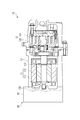
- the electric compressor 10 shown in FIG. 1 is applied to an air conditioner mounted on a vehicle.
- the electric compressor 10 includes a motor 11, a compression mechanism 12, a housing 13 accommodating the motor 11 and the compression mechanism 12, and a circuit assembly 20 carrying a circuit for driving and controlling the motor 11.
- the motor 11 includes a stator 111 fixed to the housing 13 and a rotor 112 rotated with respect to the stator 111.
- the rotor 112 is rotated by the three-phase alternating current supplied to the stator 111 by the circuit assembly 20.
- the compression mechanism 12 includes a fixed scroll 121 fixed to the housing 13 and an orbiting scroll 122 that revolves around the fixed scroll 121.
- the orbiting scroll 122 is eccentrically coupled to a shaft 113 fixed to the rotor 112.
- the housing 13 is formed in a cylindrical shape having an axis along the shaft 113.
- the motor 11 is disposed at one end in the housing 13 and the compression mechanism 12 is disposed at the other end.
- the housing 13 is supported by the engine of the vehicle with the axis oriented horizontally.
- the housing 13 has an opening 130 at one end.
- the opening 130 is closed by the circuit case 30 of the circuit assembly 20.
- the space between the peripheral edge of the opening 130 and the circuit case 30 is sealed by a packing (not shown), whereby the inside of the housing 13 is sealed.
- Electric compressor 10 operates as follows.
- the circuit assembly 20 energizes the stator 111 of the motor 11 to drive the motor 11. Further, the refrigerant is introduced into the housing 13 from a refrigerant circuit (not shown).
- the orbiting scroll 122 is orbited by the rotation of the shaft 113 by the driving force of the motor 11, the refrigerant is drawn into the compression chamber between the fixed scroll 121 and the orbiting scroll 122.
- the compression mechanism 12 compresses the refrigerant by the volume reduction of the compression chamber accompanying the turning of the turning scroll 122. The compressed refrigerant is discharged to an external refrigerant circuit.
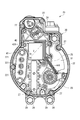
- Circuit assembly 20 is integrated into housing 13. As shown in FIGS. 2 and 3, the circuit assembly 20 includes a substrate 21 provided with various circuit elements, a plurality of circuit components 22 to 25 and 40 connected to the substrate 21, the substrate 21 and the circuit components. 22 to 25 and 40 together with a circuit case 30. In FIG. 3, the substrate 21 is removed.
- the circuit case 30 includes a partition 31 separating the inside of the circuit case 30 from the inside of the housing 13, a peripheral wall 32 rising from the peripheral edge of the partition 31, and a lid (not shown) attached to the tip of the peripheral wall 32.
- the partition 31 closes the opening 130 of the housing 13.
- the peripheral wall 32 surrounds the substrate 21 and the circuit components 22 to 25 and 40.
- a lid is fixed to the end of the peripheral wall 32 by a plurality of bolts 27.
- a packing is sandwiched between the end of the peripheral wall 32 and the lid.
- the circuit case 30 is fixed to the housing 13 with the bolts 29 by the plurality of fixing portions 28 provided outside the peripheral wall 32.
- the substrate 21 has a switching element for generating a drive signal to be supplied to the motor 11 and a circuit element such as an IC chip for driving and controlling the motor 11. Circuit elements are disposed on both the front and back sides of the substrate 21. Electric power is supplied to the substrate 21 from a battery (not shown).
- the substrate 21 is fixed to a boss 33 protruding from the partition 31 with a bolt.
- the circuit components 22 to 25 and 40 are larger in size and mass than the circuit elements provided on the substrate 21. These circuit components 22 to 25 and 40 are disposed well in the space between the substrate 21 and the partition 31 and fixed to the boss 33 projecting from the partition 31 by a bolt.
- the circuit component 22 is a switching element. The switching element is connected to a terminal on the substrate 21.
- the circuit components 23 and 24 are both coils, and the circuit component 40 is a capacitor. These coils and capacitors are used to remove noise from the drive signal.
- the circuit component 40 (capacitor) is directly fixed to the substrate 21 by the connection terminal 41 opposed to the substrate 21.
- the circuit component 25 is an electrode for electrically connecting the circuit components 23, 24, and 40 and the substrate 21 to each other.
- the circuit component 25 (electrodes) supports the circuit components 23 and 24 (coils).
- the present embodiment is characterized in a fixing structure for fixing the circuit component 40 (capacitor) to the circuit case 30.
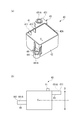
- the circuit component 40 includes a component body 42, a connection terminal 41 fixed to the substrate 21, and two fixed arms 43 and 44 fixed to the circuit case 30.
- the component main body 42 has a storage unit for storing electric charge and a case for housing the storage unit.
- the component body 42 is formed in a substantially rectangular parallelepiped shape.
- the component body 42 is disposed in a predetermined area R of the partition wall 31.
- the predetermined facing surface 42A of the component body 42 faces the substrate 21.
- connection terminal 41 is composed of a plus connection terminal 411 and a minus connection terminal 412 protruding from the facing surface 42A of the component main body 42.
- the positive connection terminal 411 and the negative connection terminal 412 are directly fixed to the substrate 21 by being inserted into recesses of terminal portions (not shown) provided on the substrate 21.
- the fixing arms 43 and 44 are provided on the component body 42 so as to project outward beyond the side surface of the component body 42 orthogonal to the facing surface 42A.
- the fixed arm 43 has a fixed portion 431 (first fixed portion) on the tip side.
- the fixed arm 44 also has a fixed portion 441 (second fixed portion) on the tip side.
- the fixing portions 431 and 441 are located around the component main body 42.
- the fixing portion 431 is formed with a bolt hole 431A. In the fixing portion 441, bolt holes 441A are formed.
- the fixing portion 431 is fixed to a boss 331 (FIG. 2) which is one of the bosses 33 of the partition 31 described above by a bolt inserted into the bolt hole 431A.
- the fixing portion 441 is fixed to a boss 332 (FIG. 2) which is one of the bosses 33 of the partition 31 described above by a bolt inserted into the bolt hole 441A.
- the present embodiment is characterized in the positions of the fixing portions 431 and 441 in order to secure the vibration resistance of the circuit component 40.
- the positions of the fixing portions 431 and 441 are determined according to the position of the center of gravity X of the circuit component 40 shown in FIGS. 4 (a) and 4 (b).
- the fixing portion 431 is positioned on the side of the substrate 21 with respect to the center of gravity X in the direction D orthogonal to the substrate 21.
- the fixing portion 441 is located on the side away from the substrate 21 with respect to the center of gravity X in the direction D orthogonal to the substrate 21.
- the fixing portions 431 and 441 have planar positions, as shown in FIG. 3, in other words, The position of the substrate 21 in the in-plane direction is also different.
- the fixing portion 431 is located on one side of a straight line L drawn so as to pass through the center of gravity X in the in-plane direction of the substrate 21.
- the fixing portion 441 is located on the other side of the straight line L.
- vibration is transmitted to the circuit assembly 20 from vibration sources such as an engine, a motor 11, a compression mechanism 12, an axle of a vehicle, and a steering device. Also, vibration is transmitted from the road surface as the vehicle travels. Therefore, the substrate 21 and the circuit components included in the circuit assembly 20 are vibrated. At this time, when the circuit component 40 that is large and has a large mass and is directly fixed to the substrate vibrates, the load applied to the connection terminal 41 and the fixing portions 431 and 441 is large, so the connection terminal 41 and the fixing portion 431, There is a high need to prevent damage to 441 in advance.
- the fixing portion 431 located on the side of the substrate 21 with respect to the center of gravity X and the fixing portion 441 located on the side separating from the substrate 21 with respect to the center of gravity X Provided in Then, compared to the case where the circuit component 40 is fixed on one side of the center of gravity X, the excitation force acting on the center of gravity X can be received in a balanced manner by the fixing portion 431 and the fixing portion 441 from both sides of the center of gravity X. The same is true for the planar direction.
- the fixing portions 431 and 441 are positioned on both sides of the straight line L passing through the center of gravity X in the in-plane direction of the substrate 21, the excitation force acting on the center of gravity X We can receive in good balance with 441. Therefore, displacement and deformation of the circuit component 40 due to vibration can be suppressed.
- the rigidity of the circuit component 40 against deformation at the time of vibration is improved. As described above, damage to the connection terminal 41 and the fixing portions 431 and 441 can be prevented even under a severe vibration environment.
- a third fixing portion can be provided in addition to the fixing portions 431 and 441. If the number of fixing parts is increased or the rigidity of the fixing parts is improved, the support strength is increased and the vibration resistance is also improved. However, in the present embodiment, by arranging the fixing portions 431 and 441 on both sides of the center of gravity X, sufficient vibration resistance of the circuit component 40 is ensured without increasing the number of fixing portions and improving the rigidity. Can.
- the fixing arms 43 and 44 can be arbitrarily configured.
- the distance from the center of gravity X to the fixed portion 431 and the distance from the center of gravity X to the fixed portion 441 are preferably smaller than the long one because deformation during vibration can be avoided if the distance is shorter.
- the circuit assembly 20 can also be fixed to the cylindrical side of the housing 13.
- the second embodiment also relates to the position of the fixing portion of the circuit component 40 provided in the circuit assembly 20 that carries the circuit for driving and controlling the motor 11 of the electric compressor 10.
- the same components as those described in the first embodiment are designated by the same reference numerals.
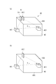
- the fixing portions 431 and 441 and the connection terminal 41 are disposed in a well-balanced manner around the center of gravity X of the circuit component 40 in order to more fully apply the excitation force to the circuit component 40. Therefore, in the present embodiment, as shown in FIG. 5A, a figure obtained by connecting the fixing portion 431, the fixing portion 441, and the connection terminal 41 to the center of gravity X of the circuit component 40 (broken line Match the centroid of the triangle). Note that the positive connection terminal 411 and the negative connection terminal 412 which are disposed close to each other are regarded as one of the apexes of a triangle.
- connection terminal 41 in order to reliably support the circuit component 40 on the connection terminal 41, it is preferable to increase the rigidity of the connection terminal 41 to be equal to that of the fixing portions 431 and 441.
- the excitation force acting on the center of gravity X of the circuit component 40 can be balancedly received.
- the excitation force acting on the center of gravity X in the direction orthogonal to the substrate 21, the in-plane direction of the substrate 21, and all other directions is a fixed portion 431, a fixed portion 441, and a vertex of a figure whose center is the center of gravity X.
- the load is equally well applied without being biased to any of the connection terminals 41.
- the rigidity against deformation at the time of vibration can be further improved, and breakage of the connection terminal 41 and the fixing portions 431 and 441 can be more reliably prevented.
- FIG. 5 (b) shows a modification of the second embodiment.
- the negative connection terminal 412 is located on the facing surface 42 A of the component body 42.
- the negative connection terminal 412 is directly fixed to the substrate 21 by being inserted into the recess of the terminal portion provided on the substrate 21.
- the positive connection terminal 411 is located on one side 42 B of the component body 42.
- the positive connection terminal 411 is connected to the substrate 21 via a connector (not shown).
- the positive connection terminal 411 is used as a fixing portion for fixing the circuit component 40 to the circuit case 30.
- the positive connection terminal 411 as a fixing portion can be fixed to a boss provided on the circuit case 30 with a bolt.
- the fixing portion 431 and 441 can be omitted.
- the fixing portion 431 is omitted and the fixing portion 441 is left.
- the center of the figure formed by the connection terminal 41 (the positive connection terminal 411 and the negative connection terminal 412) and the fixing portions 431 and 441 is completely at the center of gravity X of the circuit component 40. It does not have to match. Even if the center of the figure is shifted with respect to the center of gravity X, the same effect can be obtained.
- the center of gravity X of the circuit component 40 is positioned inside the figure formed by the connection terminal 41 and the fixing portions 431 and 441, the object can be achieved even if the center of gravity is shifted.
- the centroid and the centroid of the figure are located such that the centroid X of the circuit component 40 is located inside the figure formed by the fixing portion and the connection terminal.
- the configurations described in the above embodiment can be selected or changed to other configurations as appropriate without departing from the spirit of the present invention.
- the type of compression mechanism provided in the motor-driven compressor of the present invention and the type of motor are not limited.
- the circuit component included in the circuit assembly of the present invention is not limited to a capacitor, and can be applied to a coil and other electric and electronic elements.
Landscapes
- Engineering & Computer Science (AREA)
- Mechanical Engineering (AREA)
- General Engineering & Computer Science (AREA)
- Microelectronics & Electronic Packaging (AREA)
- Compressor (AREA)
- Applications Or Details Of Rotary Compressors (AREA)
- Mounting Components In General For Electric Apparatus (AREA)
- Mounting Of Printed Circuit Boards And The Like (AREA)
- Connection Of Motors, Electrical Generators, Mechanical Devices, And The Like (AREA)
Priority Applications (3)
| Application Number | Priority Date | Filing Date | Title |
|---|---|---|---|
| DE112014004406.7T DE112014004406B4 (de) | 2013-09-27 | 2014-09-25 | Schaltungsanordnung mit Erschütterungsfestem Schaltungskomponentenbefestigungskörper Sowie Elektrischer Verdichter für Fahrzeuge |
| US14/903,264 US20160135320A1 (en) | 2013-09-27 | 2014-09-25 | Circuit assembly with vibration-proof circuit component fixing structure, and vehicular electric compressor |
| CN201480042415.3A CN105409339B (zh) | 2013-09-27 | 2014-09-25 | 电路组件以及车辆用电动压缩机 |
Applications Claiming Priority (2)
| Application Number | Priority Date | Filing Date | Title |
|---|---|---|---|
| JP2013201793A JP6375106B2 (ja) | 2013-09-27 | 2013-09-27 | 回路部品の耐振固定構造を備えた回路組立体、および車両用電動圧縮機 |
| JP2013-201793 | 2013-09-27 |
Publications (1)
| Publication Number | Publication Date |
|---|---|
| WO2015045391A1 true WO2015045391A1 (ja) | 2015-04-02 |
Family
ID=52742560
Family Applications (1)
| Application Number | Title | Priority Date | Filing Date |
|---|---|---|---|
| PCT/JP2014/004915 Ceased WO2015045391A1 (ja) | 2013-09-27 | 2014-09-25 | 回路部品の耐振固定構造を備えた回路組立体、および車両用電動圧縮機 |
Country Status (5)
| Country | Link |
|---|---|
| US (1) | US20160135320A1 (enExample) |
| JP (1) | JP6375106B2 (enExample) |
| CN (1) | CN105409339B (enExample) |
| DE (1) | DE112014004406B4 (enExample) |
| WO (1) | WO2015045391A1 (enExample) |
Cited By (2)
| Publication number | Priority date | Publication date | Assignee | Title |
|---|---|---|---|---|
| JP2017126631A (ja) * | 2016-01-13 | 2017-07-20 | 三菱重工オートモーティブサーマルシステムズ株式会社 | 回路部品の耐振固定構造を備えた回路組立体、および車両用電動圧縮機 |
| JP2020167432A (ja) * | 2020-06-17 | 2020-10-08 | 三菱重工サーマルシステムズ株式会社 | 耐振固定構造を備えた回路部品、基板、回路組立体、および車両用電動圧縮機 |
Families Citing this family (4)
| Publication number | Priority date | Publication date | Assignee | Title |
|---|---|---|---|---|
| JP6723142B2 (ja) * | 2016-11-11 | 2020-07-15 | 三菱重工サーマルシステムズ株式会社 | コンデンサユニット、電動圧縮機 |
| JP6723141B2 (ja) * | 2016-11-11 | 2020-07-15 | 三菱重工サーマルシステムズ株式会社 | コンデンサユニット、電動圧縮機 |
| DE102023212345A1 (de) * | 2023-12-07 | 2025-06-12 | Webasto SE | Elektrische Fahrzeug-Komponente |
| WO2025244959A1 (en) * | 2024-05-19 | 2025-11-27 | Duryea Technologies, Inc. | Counterweighted rotor |
Citations (5)
| Publication number | Priority date | Publication date | Assignee | Title |
|---|---|---|---|---|
| JP2009246044A (ja) * | 2008-03-28 | 2009-10-22 | Hitachi Ltd | 電子装置、液圧ユニットおよび放熱部材固定方法 |
| JP2011011655A (ja) * | 2009-07-02 | 2011-01-20 | Nissin Kogyo Co Ltd | 液圧制御ユニットおよび車両用ブレーキ液圧制御装置 |
| JP2012106519A (ja) * | 2010-11-15 | 2012-06-07 | Bosch Corp | ブレーキ液圧制御装置 |
| WO2012096152A1 (ja) * | 2011-01-13 | 2012-07-19 | パナソニック株式会社 | 回路部品の実装構造および回路部品の実装方法 |
| JP2013167171A (ja) * | 2012-02-14 | 2013-08-29 | Mitsubishi Heavy Ind Ltd | 電動圧縮機 |
Family Cites Families (7)
| Publication number | Priority date | Publication date | Assignee | Title |
|---|---|---|---|---|
| JPS60113616U (ja) * | 1984-01-06 | 1985-08-01 | 株式会社 指月電機製作所 | 自動車電装用のコンデンサ |
| JP3178204B2 (ja) * | 1993-12-20 | 2001-06-18 | 株式会社村田製作所 | 電子部品 |
| US5659455A (en) * | 1995-03-28 | 1997-08-19 | Herbert; Edward | Packaging for electronic circuits using a capacitor as a structural member |
| EP1363026A3 (en) * | 2002-04-26 | 2004-09-01 | Denso Corporation | Invertor integrated motor for an automotive vehicle |
| JP2004019586A (ja) * | 2002-06-18 | 2004-01-22 | Sanden Corp | 電動圧縮機 |
| JP4898931B2 (ja) * | 2010-02-10 | 2012-03-21 | 三菱重工業株式会社 | インバータ一体型電動圧縮機 |
| US20120229948A1 (en) * | 2011-03-11 | 2012-09-13 | S B E, Inc. | Capacitor Used as Insulating Spacer for a High Current Bus Structure |
-
2013
- 2013-09-27 JP JP2013201793A patent/JP6375106B2/ja active Active
-
2014
- 2014-09-25 DE DE112014004406.7T patent/DE112014004406B4/de active Active
- 2014-09-25 CN CN201480042415.3A patent/CN105409339B/zh active Active
- 2014-09-25 US US14/903,264 patent/US20160135320A1/en not_active Abandoned
- 2014-09-25 WO PCT/JP2014/004915 patent/WO2015045391A1/ja not_active Ceased
Patent Citations (5)
| Publication number | Priority date | Publication date | Assignee | Title |
|---|---|---|---|---|
| JP2009246044A (ja) * | 2008-03-28 | 2009-10-22 | Hitachi Ltd | 電子装置、液圧ユニットおよび放熱部材固定方法 |
| JP2011011655A (ja) * | 2009-07-02 | 2011-01-20 | Nissin Kogyo Co Ltd | 液圧制御ユニットおよび車両用ブレーキ液圧制御装置 |
| JP2012106519A (ja) * | 2010-11-15 | 2012-06-07 | Bosch Corp | ブレーキ液圧制御装置 |
| WO2012096152A1 (ja) * | 2011-01-13 | 2012-07-19 | パナソニック株式会社 | 回路部品の実装構造および回路部品の実装方法 |
| JP2013167171A (ja) * | 2012-02-14 | 2013-08-29 | Mitsubishi Heavy Ind Ltd | 電動圧縮機 |
Cited By (8)
| Publication number | Priority date | Publication date | Assignee | Title |
|---|---|---|---|---|
| JP2017126631A (ja) * | 2016-01-13 | 2017-07-20 | 三菱重工オートモーティブサーマルシステムズ株式会社 | 回路部品の耐振固定構造を備えた回路組立体、および車両用電動圧縮機 |
| WO2017122246A1 (ja) * | 2016-01-13 | 2017-07-20 | 三菱重工オートモーティブサーマルシステムズ株式会社 | 回路部品の耐振固定構造を備えた回路組立体、および車両用電動圧縮機 |
| CN108463866A (zh) * | 2016-01-13 | 2018-08-28 | 三菱重工制冷空调系统株式会社 | 具备电路零件的耐振固定构造的电路组装体、以及车辆用电动压缩机 |
| US20190047371A1 (en) * | 2016-01-13 | 2019-02-14 | Mitsubishi Heavy Industries Thermal Systems, Ltd. | Circuit assembly having vibration-proof fixing structure for circuit component, and electric compressor for vehicle |
| US10406890B2 (en) | 2016-01-13 | 2019-09-10 | Mitsubishi Heavy Industries Thermal Systems, Ltd. | Circuit assembly having vibration-proof fixing structure for circuit component, and electric compressor for vehicle |
| CN108463866B (zh) * | 2016-01-13 | 2019-12-24 | 三菱重工制冷空调系统株式会社 | 具备电路零件的耐振固定构造的电路组装体、以及车辆用电动压缩机 |
| JP2020167432A (ja) * | 2020-06-17 | 2020-10-08 | 三菱重工サーマルシステムズ株式会社 | 耐振固定構造を備えた回路部品、基板、回路組立体、および車両用電動圧縮機 |
| JP7018992B2 (ja) | 2020-06-17 | 2022-02-14 | 三菱重工サーマルシステムズ株式会社 | 耐振固定構造を備えた回路部品、基板、回路組立体、および車両用電動圧縮機 |
Also Published As
| Publication number | Publication date |
|---|---|
| DE112014004406T5 (de) | 2016-07-14 |
| US20160135320A1 (en) | 2016-05-12 |
| CN105409339A (zh) | 2016-03-16 |
| JP6375106B2 (ja) | 2018-08-15 |
| CN105409339B (zh) | 2018-05-04 |
| JP2015070055A (ja) | 2015-04-13 |
| DE112014004406B4 (de) | 2024-02-01 |
Similar Documents
| Publication | Publication Date | Title |
|---|---|---|
| WO2015045391A1 (ja) | 回路部品の耐振固定構造を備えた回路組立体、および車両用電動圧縮機 | |
| JP5018450B2 (ja) | 電動圧縮機 | |
| JP6256382B2 (ja) | 電動圧縮機 | |
| US10087942B2 (en) | Motor driven compressor | |
| JP5120240B2 (ja) | 電動コンプレッサ | |
| JP5698007B2 (ja) | 電動コンプレッサ | |
| JP7342766B2 (ja) | 電動圧縮機 | |
| CN105247210A (zh) | 逆变器一体式电动压缩机 | |
| CN104421134A (zh) | 电动压缩机 | |
| CN102203419A (zh) | 逆变器一体型电动压缩机 | |
| JP5007169B2 (ja) | 電動コンプレッサ | |
| US10100838B2 (en) | Electric compressor including a rib structure for securing an electric component | |
| CN108463866B (zh) | 具备电路零件的耐振固定构造的电路组装体、以及车辆用电动压缩机 | |
| CN103459849B (zh) | 涡旋压缩装置 | |
| JP5726102B2 (ja) | 電動圧縮機 | |
| JP7018992B2 (ja) | 耐振固定構造を備えた回路部品、基板、回路組立体、および車両用電動圧縮機 | |
| CN111756189B (zh) | 电动压缩机 | |
| JP5726101B2 (ja) | 電動圧縮機のコンデンサ、電動圧縮機 | |
| JP5931488B2 (ja) | 電動圧縮機 | |
| WO2023190366A1 (ja) | 電動圧縮機 | |
| KR20250132383A (ko) | 전동 압축기 | |
| CN120752841A (zh) | 电动压缩机 |
Legal Events
| Date | Code | Title | Description |
|---|---|---|---|
| WWE | Wipo information: entry into national phase |
Ref document number: 201480042415.3 Country of ref document: CN |
|
| 121 | Ep: the epo has been informed by wipo that ep was designated in this application |
Ref document number: 14846866 Country of ref document: EP Kind code of ref document: A1 |
|
| WWE | Wipo information: entry into national phase |
Ref document number: 14903264 Country of ref document: US |
|
| WWE | Wipo information: entry into national phase |
Ref document number: 112014004406 Country of ref document: DE Ref document number: 1120140044067 Country of ref document: DE |
|
| 122 | Ep: pct application non-entry in european phase |
Ref document number: 14846866 Country of ref document: EP Kind code of ref document: A1 |