WO2015045144A1 - 電子機器、電子機器の制御方法、及び制御プログラム - Google Patents
電子機器、電子機器の制御方法、及び制御プログラム Download PDFInfo
- Publication number
- WO2015045144A1 WO2015045144A1 PCT/JP2013/076507 JP2013076507W WO2015045144A1 WO 2015045144 A1 WO2015045144 A1 WO 2015045144A1 JP 2013076507 W JP2013076507 W JP 2013076507W WO 2015045144 A1 WO2015045144 A1 WO 2015045144A1
- Authority
- WO
- WIPO (PCT)
- Prior art keywords
- image
- imaging
- unit
- display
- area
- Prior art date
Links
- 238000000034 method Methods 0.000 title claims description 22
- 230000008859 change Effects 0.000 claims abstract description 23
- 238000003384 imaging method Methods 0.000 claims description 548
- 230000004044 response Effects 0.000 claims description 16
- 230000008569 process Effects 0.000 claims description 14
- 238000012937 correction Methods 0.000 claims description 8
- 230000009467 reduction Effects 0.000 claims description 5
- 238000012545 processing Methods 0.000 description 140
- 230000035945 sensitivity Effects 0.000 description 60
- 230000000875 corresponding effect Effects 0.000 description 50
- 230000035508 accumulation Effects 0.000 description 46
- 238000009825 accumulation Methods 0.000 description 46
- 238000001514 detection method Methods 0.000 description 21
- 238000010586 diagram Methods 0.000 description 21
- 238000012546 transfer Methods 0.000 description 16
- 238000004891 communication Methods 0.000 description 10
- 230000003287 optical effect Effects 0.000 description 10
- 230000006870 function Effects 0.000 description 9
- 230000006835 compression Effects 0.000 description 6
- 238000007906 compression Methods 0.000 description 6
- 230000001276 controlling effect Effects 0.000 description 6
- 238000009792 diffusion process Methods 0.000 description 6
- 230000003321 amplification Effects 0.000 description 5
- 238000006243 chemical reaction Methods 0.000 description 5
- 230000033001 locomotion Effects 0.000 description 5
- 238000003199 nucleic acid amplification method Methods 0.000 description 5
- 230000000694 effects Effects 0.000 description 4
- 239000004973 liquid crystal related substance Substances 0.000 description 4
- 238000003860 storage Methods 0.000 description 4
- 230000002596 correlated effect Effects 0.000 description 3
- 239000000203 mixture Substances 0.000 description 3
- 238000012986 modification Methods 0.000 description 3
- 230000004048 modification Effects 0.000 description 3
- 230000002093 peripheral effect Effects 0.000 description 3
- 238000005070 sampling Methods 0.000 description 3
- 206010047571 Visual impairment Diseases 0.000 description 2
- 239000002131 composite material Substances 0.000 description 2
- 230000007935 neutral effect Effects 0.000 description 2
- 238000002360 preparation method Methods 0.000 description 2
- 238000003825 pressing Methods 0.000 description 2
- 238000013459 approach Methods 0.000 description 1
- 238000003491 array Methods 0.000 description 1
- 230000005540 biological transmission Effects 0.000 description 1
- 230000015572 biosynthetic process Effects 0.000 description 1
- 238000005520 cutting process Methods 0.000 description 1
- 230000007423 decrease Effects 0.000 description 1
- 238000005401 electroluminescence Methods 0.000 description 1
- 239000000284 extract Substances 0.000 description 1
- 230000004907 flux Effects 0.000 description 1
- 238000005286 illumination Methods 0.000 description 1
- 239000011159 matrix material Substances 0.000 description 1
- 238000002844 melting Methods 0.000 description 1
- 230000008018 melting Effects 0.000 description 1
- 238000002161 passivation Methods 0.000 description 1
- 238000004904 shortening Methods 0.000 description 1
- 229910052710 silicon Inorganic materials 0.000 description 1
- 239000010703 silicon Substances 0.000 description 1
- 229910000679 solder Inorganic materials 0.000 description 1
- 239000007790 solid phase Substances 0.000 description 1
- 230000002269 spontaneous effect Effects 0.000 description 1
- 238000003786 synthesis reaction Methods 0.000 description 1
- 230000002194 synthesizing effect Effects 0.000 description 1
- 238000009966 trimming Methods 0.000 description 1
- XLYOFNOQVPJJNP-UHFFFAOYSA-N water Substances O XLYOFNOQVPJJNP-UHFFFAOYSA-N 0.000 description 1
Images


Classifications
-
- H—ELECTRICITY
- H01—ELECTRIC ELEMENTS
- H01L—SEMICONDUCTOR DEVICES NOT COVERED BY CLASS H10
- H01L27/00—Devices consisting of a plurality of semiconductor or other solid-state components formed in or on a common substrate
- H01L27/14—Devices consisting of a plurality of semiconductor or other solid-state components formed in or on a common substrate including semiconductor components sensitive to infrared radiation, light, electromagnetic radiation of shorter wavelength or corpuscular radiation and specially adapted either for the conversion of the energy of such radiation into electrical energy or for the control of electrical energy by such radiation
- H01L27/144—Devices controlled by radiation
- H01L27/146—Imager structures
- H01L27/14601—Structural or functional details thereof
- H01L27/1462—Coatings
- H01L27/14621—Colour filter arrangements
-
- H—ELECTRICITY
- H04—ELECTRIC COMMUNICATION TECHNIQUE
- H04N—PICTORIAL COMMUNICATION, e.g. TELEVISION
- H04N23/00—Cameras or camera modules comprising electronic image sensors; Control thereof
- H04N23/60—Control of cameras or camera modules
- H04N23/63—Control of cameras or camera modules by using electronic viewfinders
-
- H—ELECTRICITY
- H01—ELECTRIC ELEMENTS
- H01L—SEMICONDUCTOR DEVICES NOT COVERED BY CLASS H10
- H01L27/00—Devices consisting of a plurality of semiconductor or other solid-state components formed in or on a common substrate
- H01L27/14—Devices consisting of a plurality of semiconductor or other solid-state components formed in or on a common substrate including semiconductor components sensitive to infrared radiation, light, electromagnetic radiation of shorter wavelength or corpuscular radiation and specially adapted either for the conversion of the energy of such radiation into electrical energy or for the control of electrical energy by such radiation
- H01L27/144—Devices controlled by radiation
- H01L27/146—Imager structures
- H01L27/14601—Structural or functional details thereof
- H01L27/14625—Optical elements or arrangements associated with the device
- H01L27/14627—Microlenses
-
- H—ELECTRICITY
- H04—ELECTRIC COMMUNICATION TECHNIQUE
- H04N—PICTORIAL COMMUNICATION, e.g. TELEVISION
- H04N25/00—Circuitry of solid-state image sensors [SSIS]; Control thereof
- H04N25/10—Circuitry of solid-state image sensors [SSIS]; Control thereof for transforming different wavelengths into image signals
- H04N25/11—Arrangement of colour filter arrays [CFA]; Filter mosaics
- H04N25/13—Arrangement of colour filter arrays [CFA]; Filter mosaics characterised by the spectral characteristics of the filter elements
- H04N25/134—Arrangement of colour filter arrays [CFA]; Filter mosaics characterised by the spectral characteristics of the filter elements based on three different wavelength filter elements
-
- H—ELECTRICITY
- H04—ELECTRIC COMMUNICATION TECHNIQUE
- H04N—PICTORIAL COMMUNICATION, e.g. TELEVISION
- H04N25/00—Circuitry of solid-state image sensors [SSIS]; Control thereof
- H04N25/40—Extracting pixel data from image sensors by controlling scanning circuits, e.g. by modifying the number of pixels sampled or to be sampled
-
- H—ELECTRICITY
- H04—ELECTRIC COMMUNICATION TECHNIQUE
- H04N—PICTORIAL COMMUNICATION, e.g. TELEVISION
- H04N25/00—Circuitry of solid-state image sensors [SSIS]; Control thereof
- H04N25/70—SSIS architectures; Circuits associated therewith
-
- H—ELECTRICITY
- H04—ELECTRIC COMMUNICATION TECHNIQUE
- H04N—PICTORIAL COMMUNICATION, e.g. TELEVISION
- H04N25/00—Circuitry of solid-state image sensors [SSIS]; Control thereof
- H04N25/70—SSIS architectures; Circuits associated therewith
- H04N25/76—Addressed sensors, e.g. MOS or CMOS sensors
- H04N25/77—Pixel circuitry, e.g. memories, A/D converters, pixel amplifiers, shared circuits or shared components
-
- H—ELECTRICITY
- H04—ELECTRIC COMMUNICATION TECHNIQUE
- H04N—PICTORIAL COMMUNICATION, e.g. TELEVISION
- H04N25/00—Circuitry of solid-state image sensors [SSIS]; Control thereof
- H04N25/70—SSIS architectures; Circuits associated therewith
- H04N25/79—Arrangements of circuitry being divided between different or multiple substrates, chips or circuit boards, e.g. stacked image sensors
-
- H—ELECTRICITY
- H04—ELECTRIC COMMUNICATION TECHNIQUE
- H04N—PICTORIAL COMMUNICATION, e.g. TELEVISION
- H04N23/00—Cameras or camera modules comprising electronic image sensors; Control thereof
- H04N23/60—Control of cameras or camera modules
- H04N23/667—Camera operation mode switching, e.g. between still and video, sport and normal or high- and low-resolution modes
Definitions
- the present invention relates to an electronic device, an electronic device control method, and a control program.
- an electronic device including an imaging element in which a backside illumination type imaging chip and a signal processing chip are stacked (hereinafter, this imaging element is referred to as a multilayer imaging element) has been proposed (for example, see Patent Document 1).
- the multilayer imaging element is laminated so that the back-illuminated imaging chip and the signal processing chip are connected via a micro bump for each block unit including a plurality of pixels.
- An aspect of the present invention aims to confirm a change in an image corresponding to a change in imaging conditions by displaying a plurality of images captured under different imaging conditions on a display unit.
- a plurality of first imaging elements that perform imaging under the first imaging condition and second imaging elements that perform imaging under a second imaging condition different from the first imaging condition are arranged, and the first An imaging unit that outputs first image data generated according to a subject image incident on the image sensor and second image data generated according to a subject image incident on the second image sensor, and the first image data A control unit that displays the first image to be displayed and the second image represented by the second image data on the display unit so as to select the recording mode of the first image data and the second image data.
- Electronic equipment is provided.
- a plurality of first imaging elements that perform imaging under the first imaging condition and a plurality of second imaging elements that perform imaging under a second imaging condition different from the first imaging condition are arranged.
- Method for controlling an electronic apparatus having an imaging unit that outputs first image data generated according to a subject image incident on an image sensor and second image data generated according to a subject image incident on a second image sensor The first image indicated by the first image data and the second image indicated by the second image data are displayed on the display unit so that the recording mode of the first image data and the second image data can be selected.
- a method for controlling an electronic device is provided.
- a plurality of first imaging elements that perform imaging under the first imaging condition and a plurality of second imaging elements that perform imaging under a second imaging condition different from the first imaging condition are arranged.
- Control apparatus for an electronic device having an imaging unit that outputs first image data generated according to a subject image incident on an image sensor and second image data generated according to a subject image incident on a second image sensor
- the first image indicated by the first image data and the second image indicated by the second image data are displayed on the display unit so that the recording mode of the first image data and the second image data can be selected.
- a control program for executing the processing to be performed is provided.
- the aspect of the present invention it is possible to confirm the change of the image corresponding to the change of the imaging condition by displaying the plurality of images captured under the different imaging conditions on the display unit.
- FIG. 1 is a cross-sectional view of the image sensor 100 of the present embodiment.
- the image sensor 100 is described in Japanese Patent Application No. 2012-139026 filed earlier by the applicant of the present application.
- the imaging device 100 includes an imaging chip 113 that outputs a pixel signal corresponding to incident light, a signal processing chip 111 that processes the pixel signal output from the imaging chip 113, and a memory that stores the pixel signal processed by the signal processing chip 111.
- the imaging chip 113, the signal processing chip 111, and the memory chip 112 are stacked, and the imaging chip 113 and the signal processing chip 111 are electrically connected to each other by a conductive bump 109 such as Cu. Further, the signal processing chip 111 and the memory chip 112 are electrically connected to each other by a conductive bump 109 such as Cu.
- incident light is incident mainly in the positive direction of the Z axis.
- the surface on the side where incident light is incident is referred to as a back surface.
- the left direction on the paper orthogonal to the Z axis is the X axis plus direction
- the front side of the paper orthogonal to the Z axis and the X axis is the Y axis plus direction.
- the coordinate axes are displayed so that the orientation of each figure can be understood with reference to the coordinate axes of FIG.
- the imaging chip 113 is a back-illuminated MOS image sensor.
- the PD layer 106 is disposed on the back side of the wiring layer 108.
- the PD layer 106 includes a plurality of photodiodes (Photodiode; hereinafter referred to as PD) 104 that are two-dimensionally arranged and accumulate electric charges according to incident light, and a transistor 105 provided corresponding to the PD 104. .
- a color filter 102 is provided on the incident light incident side of the PD layer 106 via a passivation film 103.
- the color filter 102 is a filter that passes a specific wavelength region of visible light.
- the color filter 102 has a plurality of types that transmit different wavelength regions, and has a specific arrangement corresponding to each of the PDs 104. The arrangement of the color filter 102 will be described later.
- a set of the color filter 102, the PD 104, and the transistor 105 forms one pixel.
- a microlens 101 is provided on the incident light incident side of the color filter 102 corresponding to each pixel.
- the microlens 101 condenses incident light toward the corresponding PD 104.
- the wiring layer 108 includes a wiring 107 that transmits a pixel signal from the PD layer 106 to the signal processing chip 111.
- the wiring 107 may be multilayer, and a passive element and an active element may be provided.
- a plurality of bumps 109 are disposed on the surface of the wiring layer 108. The plurality of bumps 109 are aligned with the plurality of bumps 109 provided on the opposing surface of the signal processing chip 111. Then, by pressing the imaging chip 113 and the signal processing chip 111, the aligned bumps 109 are joined and electrically connected.
- a plurality of bumps 109 are arranged on the mutually facing surfaces of the signal processing chip 111 and the memory chip 112. These bumps 109 are aligned with each other. Then, when the signal processing chip 111 and the memory chip 112 are pressurized or the like, the aligned bumps 109 are joined and electrically connected.
- the bonding between the bumps 109 is not limited to Cu bump bonding by solid phase diffusion, and micro bump bonding by solder melting may be employed. Further, for example, about one bump 109 may be provided for one unit group described later. Therefore, the size of the bump 109 may be larger than the pitch of the PD 104. In addition, a bump larger than the bump 109 corresponding to the pixel region may be provided in a peripheral region other than the pixel region where the pixels are arranged (the pixel region 113A shown in FIG. 2).
- the signal processing chip 111 has a TSV (Through-Silicon Via) 110 that connects circuits provided on the front and back surfaces to each other.
- the TSV 110 is provided in the peripheral area.
- the TSV 110 may be provided in the peripheral area of the imaging chip 113 or the memory chip 112.
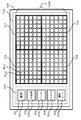
- FIG. 2 is a diagram for explaining a pixel array and a unit group of the imaging chip 113.
- FIG. 2 particularly shows a state where the imaging chip 113 is observed from the back side.
- An area where pixels are arranged in the imaging chip 113 is referred to as a pixel area (imaging area) 113A.
- a pixel area (imaging area) 113A 20 million or more pixels are arranged in a matrix.
- 16 pixels of 4 pixels ⁇ 4 pixels adjacent to each other form one unit group 131.
- the grid lines in FIG. 2 indicate a concept in which adjacent pixels are grouped to form a unit group 131.
- the number of pixels forming the unit group 131 is not limited to this, and may be about 1000, for example, 32 pixels ⁇ 64 pixels, or more or less.
- the unit group 131 includes four so-called Bayer arrays, which are composed of four pixels of green pixels Gb and Gr, a blue pixel B, and a red pixel R, vertically and horizontally.
- the green pixel is a pixel having a green filter as the color filter 102, and receives light in the green wavelength band of incident light.
- the blue pixel is a pixel having a blue filter as the color filter 102 and receives light in the blue wavelength band.
- the red pixel is a pixel having a red filter as the color filter 102 and receives light in the red wavelength band.
- FIG. 3 is a circuit diagram corresponding to a unit group of the imaging chip 113.
- a rectangle surrounded by a dotted line typically represents a circuit corresponding to one pixel. Note that at least some of the transistors described below correspond to the transistor 105 in FIG.
- the unit group 131 is formed of 16 pixels.
- the 16 PDs 104 corresponding to the respective pixels are each connected to the transfer transistor 302.
- the gate of each transfer transistor 302 is connected to a TX wiring 307 to which a transfer pulse is supplied.
- the TX wiring 307 is commonly connected to the 16 transfer transistors 302.
- each transfer transistor 302 is connected to the source of the corresponding reset transistor 303, and a so-called floating diffusion FD (charge detection unit) between the drain of the transfer transistor 302 and the source of each reset transistor 303 is connected to the amplifier transistor 304. Connected to the gate.
- the drain of each reset transistor 303 is connected to a Vdd wiring 310 to which a power supply voltage is supplied.
- the gate of each reset transistor 303 is connected to a reset wiring 306 to which a reset pulse is supplied.
- the reset wiring 306 is commonly connected to the 16 reset transistors 303.
- each amplification transistor 304 is connected to a Vdd wiring 310 to which a power supply voltage is supplied.
- the source of each amplification transistor 304 is connected to the drain of each corresponding selection transistor 305.
- the gate of each selection transistor 305 is connected to a decoder wiring 308 to which a selection pulse is supplied.
- the decoder wiring 308 is provided independently for each of the 16 selection transistors 305.
- the source of each selection transistor 305 is connected to a common output wiring 309.
- the load current source 311 supplies current to the output wiring 309. That is, the output wiring 309 for the selection transistor 305 is formed by a source follower. Note that the load current source 311 may be provided on the imaging chip 113 side or may be provided on the signal processing chip 111 side.
- a reset pulse is applied to the reset transistor 303 through the reset wiring 306.
- a transfer pulse is applied to the transfer transistor 302 through the TX wiring 307.
- the potentials of the PD 104 and the floating diffusion FD are reset.
- the PD 104 converts the incident light received into charges and accumulates them. Thereafter, when the transfer pulse is applied again without the reset pulse being applied, the charge accumulated in the PD 104 is transferred to the floating diffusion FD. As a result, the potential of the floating diffusion FD changes from the reset potential to the signal potential after charge accumulation.
- a selection pulse is applied to the selection transistor 305 through the decoder wiring 308, the change in the signal potential of the floating diffusion FD is transmitted to the output wiring 309 through the amplification transistor 304 and the selection transistor 305.
- the reset wiring 306 and the TX wiring 307 are common to the 16 pixels forming the unit group 131. That is, the reset pulse and the transfer pulse are simultaneously applied to all 16 pixels. Therefore, all the pixels forming the unit group 131 start charge accumulation at the same timing and end charge accumulation at the same timing. However, the pixel signal corresponding to the accumulated charge is selectively output to the output wiring 309 by sequentially applying the selection pulse to each selection transistor 305. In addition, the reset wiring 306, the TX wiring 307, and the output wiring 309 are provided separately for each unit group 131.
- the charge accumulation time can be controlled for each unit group 131.
- pixel signals with different charge accumulation times can be output between the unit groups 131. More specifically, while one unit group 131 performs charge accumulation once, the other unit group 131 repeats charge accumulation several times and outputs a pixel signal each time, so that Each frame for moving images can be output at a different frame rate between the unit groups 131.
- FIG. 4 is a block diagram showing a functional configuration of the image sensor 100.
- the analog multiplexer 411 sequentially selects the 16 PDs 104 that form the unit group 131. Then, the multiplexer 411 outputs each pixel signal of the 16 PDs 104 to the output wiring 309 provided corresponding to the unit group 131.
- the multiplexer 411 is formed on the imaging chip 113 together with the PD 104.
- the pixel signal of the analog signal output via the multiplexer 411 is amplified by the amplifier 412 formed in the signal processing chip 111. Then, the pixel signal amplified by the amplifier 412 is processed by a signal processing circuit 413 that performs correlated double sampling (CDS) and analog / digital (Analog / Digital) conversion, which is formed in the signal processing chip 111. Correlated double sampling signal processing is performed, and A / D conversion (conversion from an analog signal to a digital signal) is performed. The pixel signal is subjected to correlated double sampling signal processing in the signal processing circuit 413, whereby noise of the pixel signal is reduced. The A / D converted pixel signal is transferred to the demultiplexer 414 and stored in the pixel memory 415 corresponding to each pixel. The demultiplexer 414 and the pixel memory 415 are formed in the memory chip 112.
- CDS correlated double sampling
- analog / digital Analog / Digital
- the arithmetic circuit 416 processes the pixel signal stored in the pixel memory 415 and passes it to the subsequent image processing unit.
- the arithmetic circuit 416 may be provided in the signal processing chip 111 or may be provided in the memory chip 112. Note that FIG. 4 shows connections for one unit group 131, but actually these exist for each unit group 131 and operate in parallel. However, the arithmetic circuit 416 may not exist for each unit group 131. For example, one arithmetic circuit 416 may perform sequential processing while sequentially referring to the values in the pixel memory 415 corresponding to each unit group 131.
- the output wiring 309 is provided corresponding to each of the unit groups 131.
- the image sensor 100 has an image pickup chip 113, a signal processing chip 111, and a memory chip 112 stacked. For this reason, by using the electrical connection between the chips using the bumps 109 for the output wirings 309, the wirings can be routed without enlarging each chip in the surface direction.
- the pixel region 113A of the image sensor 100 is divided into a plurality of blocks.
- the plurality of blocks are defined to include at least one unit group 131 per block.
- pixels included in each block are controlled by different control parameters. That is, pixel signals having different control parameters are acquired for a pixel group included in a block and a pixel group included in another block.
- the control parameters include, for example, charge accumulation time or accumulation count, frame rate, gain, decimation rate (pixel decimation rate), number of addition rows or addition columns (pixel addition number) for adding pixel signals, digitization bit Numbers are given.
- the control parameter may be a parameter in image processing after obtaining an image signal from a pixel.
- the charge accumulation time refers to the time from the start of PD 104 accumulation until the end. This charge accumulation time is also referred to as exposure time or shutter speed (shutter speed).
- the number of times of charge accumulation refers to the number of times the PD 104 accumulates charges per unit time.
- the frame rate is a value representing the number of frames processed (displayed or recorded) per unit time in a moving image. The unit of the frame rate is expressed by fps (Frames Per Second). The higher the frame rate, the smoother the movement of the subject (that is, the object to be imaged) in the moving image.
- the gain means a gain factor (amplification factor) of the amplifier 412.
- This ISO sensitivity is a photographic film standard established by ISO and represents how much light the photographic film can record.
- ISO sensitivity is also used when expressing the sensitivity of the image sensor 100.
- the ISO sensitivity is a value representing the ability of the image sensor 100 to capture light.
- Increasing the gain improves the ISO sensitivity. For example, when the gain is doubled, the electrical signal (pixel signal) is also doubled, and the brightness is appropriate even when the amount of incident light is half.
- the gain is increased, noise included in the electric signal is also amplified, so that noise increases.
- the thinning-out rate refers to the ratio of the number of pixels in which pixel signals are not read out with respect to the total number of pixels in a predetermined area. For example, when the thinning rate of a predetermined area is 0, it means that pixel signals are read from all pixels in the predetermined area. Further, when the thinning rate of the predetermined area is 0.5, it means that the pixel signal is read from half of the pixels in the predetermined area. Specifically, when the unit group 131 is a Bayer array, it is read as a pixel from which pixel signals are alternately read out every other unit of the Bayer array in the vertical direction, that is, every two pixels (two rows) of the pixel unit. Pixels that are not output are set.
- the resolution of the image is reduced when the pixel signal readout is thinned out.
- 20 million or more pixels are arranged in the image sensor 100, for example, even if thinning is performed at a thinning rate of 0.5, an image can be displayed with 10 million or more pixels. For this reason, it is considered that the reduction in resolution is not a concern for the user (photographer).
- the number of added rows refers to the number of vertical pixels (number of rows) to be added when pixel signals of pixels adjacent in the vertical direction are added.
- the number of added columns refers to the number of horizontal pixels (number of columns) to be added when pixel signals of pixels adjacent in the horizontal direction are added.
- Such addition processing is performed in the arithmetic circuit 416, for example.
- the arithmetic circuit 416 performs the process of adding the pixel signals of a predetermined number of pixels adjacent in the vertical direction or the horizontal direction, thereby obtaining the same effect as the process of reading out the pixel signals by thinning out at a predetermined thinning rate.
- the average value may be calculated by dividing the added value by the number of rows or columns added by the arithmetic circuit 416.
- the digitization bit number refers to the bit number when the signal processing circuit 413 converts an analog signal into a digital signal in A / D conversion. As the number of bits of the digital signal increases, brightness, color change, and the like are expressed in more detail.
- the accumulation condition refers to a condition related to charge accumulation in the image sensor 100.
- the accumulation condition refers to the charge accumulation time or number of accumulations, the frame rate, and the gain among the control parameters described above. Since the frame rate can change according to the charge accumulation time and the number of times of accumulation, the frame rate is included in the accumulation condition. Further, the amount of light for proper exposure changes according to the gain, and the charge accumulation time or number of times of accumulation can also change according to the amount of light for proper exposure. For this reason, the gain is included in the accumulation condition.
- the imaging condition refers to a condition related to imaging of a subject.
- the imaging condition refers to a control parameter including the above accumulation condition.
- the imaging conditions include control parameters (for example, charge accumulation time or accumulation count, frame rate, gain) for controlling the image sensor 100, as well as control parameters (for controlling reading of signals from the image sensor 100). For example, a thinning rate, the number of addition rows or addition columns for adding pixel signals, and control parameters for processing signals from the image sensor 100 (for example, the number of bits for digitization, the image processing unit 30 described later performs image processing) Is also included.
- FIG. 5 is a diagram showing an arrangement pattern in each block.
- the array pattern shown in FIG. 5 is an array pattern in which the pixel area 113A is divided into four imaging areas (a first imaging area, a second imaging area, a third imaging area, and a fourth imaging area).
- the pixel region 113A in which the pixel area 113A, the block in the odd row (2n-1) in the column (4m-3) three columns before the column that is a multiple of 4 and the column one column before the column that is a multiple of 4
- the first imaging region is composed of the even-numbered rows (2n) in (4m ⁇ 1).
- Blocks constitute a second imaging area.
- an odd row (2n-1) block in a column (4m-1) one column before a column that is a multiple of 4 and a column (4m-
- the third imaging region is composed of the even-numbered row (2n) blocks in 3).
- Blocks constitute a fourth imaging region.
- a small number of blocks are set in the pixel region 113A in order to make the arrangement of the blocks for each imaging region easy to see, but a larger number of blocks than the number of blocks shown in FIG. You may make it set to the area
- the first imaging area, the second imaging area, the third imaging area, and the fourth imaging area are equally arranged in the pixel area (imaging area) 113A.
- the first imaging area, the second imaging area, the third imaging area, and the fourth imaging area have the same area.
- the first imaging area, the second imaging area, the third imaging area, and the fourth imaging area only have to be arranged on the entire surface in the pixel area 113A, and are not arranged equally in the pixel area 113A. Also good. Further, the first imaging area, the second imaging area, the third imaging area, and the fourth imaging area may not have the same area.
- the first imaging area, the second imaging area, the third imaging area, and the fourth imaging area are arranged at different positions (that is, the positions of the imaging areas are shifted). Therefore, different subject images are incident on the first imaging area, the second imaging area, the third imaging area, and the fourth imaging area, respectively. Accordingly, the images indicated by the image data generated in each of the first imaging region, the second imaging region, the third imaging region, and the fourth imaging region are different subject images. However, the first imaging area, the second imaging area, the third imaging area, and the fourth imaging area are all arranged in the pixel area 113A. For this reason, the image indicated by the image data generated in each of the first imaging region, the second imaging region, the third imaging region, and the fourth imaging region appears to the user as the same subject image.
- each image sensor (photoelectric conversion element and its associated circuit) provided in each pixel in the first image pickup region is referred to as a first image sensor
- each image sensor provided in each pixel in the second image pickup region is referred to as a first image sensor
- Each image sensor provided in each pixel in the third image pickup area is referred to as a second image sensor
- each image sensor provided in each pixel in the fourth image pickup area is referred to as a fourth image sensor. That is, the image sensor 100 is divided into a plurality of first image sensors, a plurality of second image sensors, a plurality of third image sensors, and a plurality of fourth image sensors.
- the first image sensor, the second image sensor, the third image sensor, and the fourth image sensor capture images under different image capturing conditions.
- the imaging condition of the first imaging element is referred to as the first imaging condition
- the imaging condition of the second imaging element is referred to as the second imaging condition
- the imaging condition of the third imaging element is referred to as the third imaging condition
- the fourth imaging element The imaging condition is referred to as a fourth imaging condition.
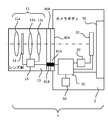
- FIG. 6 is a cross-sectional view showing a schematic configuration of a digital camera 1 which is an example of an electronic device.
- the digital camera 1 of this embodiment includes a lens unit 10 and a camera body 2.
- the lens unit 10 is an interchangeable lens.
- the camera body 2 is provided with a body side mount portion 80A for mounting the lens portion 10.
- the lens unit 10 is provided with a lens side mount unit 80B corresponding to the body side mount unit 80A.
- the lens unit 10 is attached to the camera body 2 when the user joins the body side mount 80A and the lens side mount 80B.
- the electrical contact 81A provided on the body side mount 80A and the electrical contact 81B provided on the lens side mount 80B are electrically connected.
- the lens unit 10 includes a photographing optical system 11, a diaphragm 14, and a lens drive control device 15.
- the imaging optical system 11 includes a lens 11a, a zooming lens 11b, and a focusing lens 11c.
- the lens drive control device 15 includes a lens side CPU (Central Processing). Unit), a memory, and a drive control circuit.
- the lens drive control device 15 is electrically connected to the system control unit 70 on the camera body 2 side via the electrical contacts 81A and 81B, and transmits lens information relating to the optical characteristics of the photographing optical system 11 provided in the lens unit 10. Control information for driving the zooming lens 11b, the focusing lens 11c, and the aperture stop 14 is received.
- the lens side CPU of the lens drive control device 15 causes the drive control circuit to execute drive control of the focusing lens 11c based on control information transmitted from the system control unit 70 in order to adjust the focus of the photographing optical system 11.
- the lens side CPU of the lens drive control device 15 causes the drive control circuit to execute drive control of the zooming lens 11b based on control information transmitted from the system control unit 70 in order to perform zooming adjustment.
- the diaphragm 14 is disposed along the optical axis of the photographing optical system 11.
- the aperture 14 forms an aperture with a variable aperture diameter at the center of the optical axis in order to adjust the amount of light and the amount of blur.
- the lens side CPU of the lens drive control device 15 causes the drive control circuit to perform drive control of the diaphragm 14 based on control information transmitted from the system control unit 70 in order to adjust the aperture diameter of the diaphragm 14.
- the camera body 2 includes an imaging unit 20, an image processing unit 30, a display unit 50, a storage unit 60, and a system control unit 70.
- the imaging unit 20 includes an imaging element 100.
- a light beam emitted from the photographing optical system 11 of the lens unit 10 is incident on the image sensor 100.
- the image sensor 100 photoelectrically converts an incident light beam to generate a pixel signal (pixel signal is included in image data) of each pixel of the image sensor.
- RAW data (RAW data is also included in the image data) composed of pixel signals of each pixel is sent from the imaging unit 20 to the image processing unit 30.
- the image processing unit 30 performs various kinds of image processing on the RAW data including the pixel signal of each pixel, and generates image data in a predetermined file format (for example, JPEG format).
- the display unit 50 displays the image data generated by the image processing unit 30.
- the storage unit 60 stores the image data generated by the image processing unit 30.
- image data is sometimes referred to as “image signal”.
- the images include still images, moving images, and live view images.
- the live view image is an image displayed on the display unit 50 by sequentially outputting the image data generated by the image processing unit 30 to the display unit 50.
- the live view image is used for the user to confirm the image of the subject imaged by the imaging unit 20.
- the live view image is also called a through image or a preview image.
- the system control unit 70 controls the overall processing and operation of the digital camera 1. Details of processing and operation of the system control unit 70 and details of the configuration in the camera body 2 will be described with reference to FIG.
- FIG. 7 is a block diagram showing the configuration of the digital camera 1 according to the first embodiment.
- the digital camera 1 includes a camera body 2 and a lens unit 10.
- the lens unit 10 is an interchangeable lens that can be attached to and detached from the camera body 2. Therefore, the digital camera 1 may not include the lens unit 10. However, the lens unit 10 may be integrated with the digital camera 1.
- the lens unit 10 guides the luminous flux from the subject to the imaging unit 20 in a state where the lens unit 10 is connected to the camera body 2.
- the lens unit 10 has the lens drive control device 15 as described above (see FIG. 6).
- the lens unit 10 includes a plurality of lens groups as the photographing optical system 11, that is, a lens 11a, a zooming lens 11b, and a focusing lens 11c.
- the lens drive control device 15 transmits lens information stored in the memory to the system control unit 70 of the camera body 2.
- the lens drive control device 15 receives control information transmitted from the system control unit 70 when the lens unit 10 is connected to the camera body 2.
- the lens drive control device 15 performs drive control of the zooming lens 11b, the focusing lens 11c, and the diaphragm 14 based on the control information.
- the camera body 2 includes an imaging unit 20, an image processing unit 30, a work memory 40, a display unit 50, an operation unit 55, a recording unit 60, a system control unit 70, and a strobe 90.
- the imaging unit 20 includes an imaging device 100 and a driving unit 21.
- the drive unit 21 is a control circuit that controls driving of the image sensor 100 in accordance with an instruction from the system control unit 70.
- the drive unit 21 controls the timing (or timing cycle) at which the reset pulse and the transfer pulse are applied to the reset transistor 303 and the transfer transistor 302, respectively, thereby reducing the charge accumulation time or accumulation count as a control parameter. Control.
- the drive unit 21 controls the frame rate by controlling the timing (or timing cycle) at which the reset pulse, the transfer pulse, and the selection pulse are applied to the reset transistor 303, the transfer transistor 302, and the selection transistor 305, respectively.
- the drive unit 21 controls the thinning rate by setting pixels to which the reset pulse, the transfer pulse, and the selection pulse are applied.
- the drive unit 21 controls the ISO sensitivity of the image sensor 100 by controlling the gain (also referred to as gain factor or amplification factor) of the amplifier 412. In addition, the drive unit 21 sends an instruction to the arithmetic circuit 416 to set the number of added rows or the number of added columns to which pixel signals are added. Further, the drive unit 21 sets the number of bits for digitization by sending an instruction to the signal processing circuit 413. Furthermore, the drive unit 21 sets areas in units of blocks in the pixel area (imaging area) 113 ⁇ / b> A of the image sensor 100. In this way, the drive unit 21 functions as an image sensor control unit that causes the image sensor 100 to capture an image under different image capturing conditions for each of a plurality of blocks and output a pixel signal. The system control unit 70 instructs the drive unit 21 on the block position, shape, range, and the like.
- the image sensor 100 delivers the pixel signal from the image sensor 100 to the image processing unit 30.
- the image processing unit 30 uses the work memory 40 as a work space, performs various image processing on the RAW data including pixel signals of each pixel, and generates image data in a predetermined file format (for example, JPEG format). .
- the image processing unit 30 executes the following image processing.
- the image processing unit 30 generates an RGB image signal by performing color signal processing (color tone correction) on a signal obtained by the Bayer array.
- the image processing unit 30 performs image processing such as white balance adjustment, sharpness adjustment, gamma correction, and gradation adjustment on the RGB image signal.
- the image processing unit 30 performs a process of compressing in a predetermined compression format (JPEG format, MPEG format, etc.) as necessary.
- the image processing unit 30 outputs the generated image data to the recording unit 60.
- the image processing unit 30 outputs the generated image data to the display unit 50.
- Parameters that are referred to when the image processing unit 30 performs image processing are also included in the control parameters (imaging conditions). For example, parameters such as color signal processing (tone correction), white balance adjustment, gradation adjustment, and compression rate are included in the control parameters.
- the signal read from the image sensor 100 changes according to the charge accumulation time, and the parameters referred to when performing image processing also change according to the change in the signal.
- the image processing unit 30 sets different control parameters for each block, and executes image processing such as color signal processing based on these control parameters.
- the image processing unit 30 extracts frames at predetermined timings from among a plurality of frames obtained in time series from the imaging unit 20. Alternatively, the image processing unit 30 discards frames at a predetermined timing among a plurality of frames obtained in time series from the imaging unit 20. Thereby, since the amount of data can be reduced, it is possible to reduce the load of subsequent processing. Further, the image processing unit 30 calculates one or a plurality of frames to be interpolated between the frames based on a plurality of frames obtained in time series from the imaging unit 20. Then, the image processing unit 30 adds the calculated one or more frames between the frames. As a result, a moving image with smoother motion can be reproduced during moving image reproduction.
- the drive part 21 is comprised so that the thinning-out rate may be controlled, it is not restricted to such a structure.
- the drive unit 21 reads pixel signals from all pixels, but the image processing unit 30 or the arithmetic circuit 416 controls the thinning rate by discarding predetermined pixel signals out of the read pixel signals. Good.
- the image processing unit 30 includes an image generation unit 31 as shown in FIG.
- the image generation unit 31 generates image data by performing various kinds of image processing on the RAW data including pixel signals of each pixel output from the imaging unit 20.
- the image generation unit 31 generates first image data based on RAW data composed of pixel signals in the first imaging region, generates second image data based on RAW data composed of pixel signals in the second imaging region, Third image data is generated based on RAW data composed of pixel signals in the third imaging region, and fourth image data is generated based on RAW data composed of pixel signals in the fourth imaging region.
- the work memory 40 temporarily stores image data and the like when image processing by the image processing unit 30 is performed.
- the display unit 50 displays images (still images, moving images, live view images) and various types of information captured by the imaging unit 20.
- the display unit 50 includes a display surface (display panel) 51 such as a liquid crystal display panel.
- a touch panel (selection unit) 52 is formed on the display surface 51 of the display unit 50.
- the touch panel 52 outputs a signal indicating the position touched by the user to the system control unit 70 when the user performs an operation such as menu selection.
- the operation unit 55 includes a release switch (a switch that is pressed when shooting a still image), a moving image switch (a switch that is pressed when shooting an operation), and various operation switches that are operated by the user.
- the operation unit 55 outputs a signal corresponding to the operation by the user to the system control unit 70.
- the recording unit 60 has a card slot into which a storage medium such as a memory card can be mounted.
- the recording unit 60 stores the image data and various data generated by the image processing unit 30 in a recording medium mounted in the card slot.
- the recording unit 60 has an internal memory.
- the recording unit 60 can also record the image data and various data generated by the image processing unit 30 in the internal memory.
- the system control unit 70 controls the overall processing and operation of the digital camera 1.
- the system control unit 70 has a body side CPU (Central Processing Unit).
- the system control unit 70 divides the imaging surface (pixel area 113A) of the imaging device 100 (imaging chip 113) into a plurality of blocks, and different charge accumulation times (or charge accumulation times) and frame rates among the blocks. Get an image with a gain. Therefore, the system control unit 70 instructs the drive unit 21 about the block position, shape, range, and accumulation condition for each block.
- the system control unit 70 acquires images with different thinning rates between blocks, the number of added rows or added columns to which pixel signals are added, and the number of digitization bits. For this reason, the system control unit 70 instructs the drive unit 21 on the imaging conditions for each block (the thinning rate, the number of added rows or columns to which pixel signals are added, and the number of digitization bits). Further, the image processing unit 30 executes image processing under imaging conditions (control parameters such as color signal processing, white balance adjustment, gradation adjustment, and compression rate) that are different between blocks. For this reason, the system control unit 70 instructs the image processing unit 30 on the imaging conditions for each block (control parameters such as color signal processing, white balance adjustment, gradation adjustment, and compression rate).
- system control unit 70 causes the recording unit 60 to record the image data generated in the image processing unit 30. Further, the system control unit 70 causes the display unit 50 to display an image by causing the display unit 50 to output the image data generated in the image processing unit 30. Further, the system control unit 70 causes the display unit 50 to display an image by reading out the image data recorded in the recording unit 60 and causing the display unit 50 to output the image data.
- the images displayed on the display unit 50 include still images, moving images, and live view images.
- system control unit 70 outputs control information to the lens drive control device 15 to cause the lens drive control device 15 to execute drive control of the focusing lens 11 c and drive control of the aperture 14.
- the system control unit 70 is realized by the body side CPU executing processing based on the control program.
- the system control unit 70 includes a control unit 71, a selection unit 72, a setting unit 73, and a division unit 74 as shown in FIG.
- the control unit 71 controls the display unit 50 to display the image on the display surface 51 of the display unit 50 by causing the display unit 50 to output the image data generated by the image generation unit 31.
- the control unit 71 performs control to display a preset menu image (see FIG. 8) on the display surface 51 of the display unit 50.
- the selection unit 72 selects one of the four display areas (the first display area 511, the second display area 512, the third display area 513, and the fourth display area 514) according to the touch operation of the touch panel 52 by the user. Perform control to select.
- the setting unit 73 performs control for setting imaging conditions (including storage conditions) in response to a touch operation on the touch panel 52 by the user or automatically.
- the setting unit 73 can set the same imaging condition in all the pixel regions 113A of the imaging element 100.
- the setting unit 73 can set different imaging conditions in each imaging region (first imaging region, second imaging region, third imaging region, and fourth imaging region) illustrated in FIG.
- the setting unit 73 performs control to cause the image sensor 100 to perform imaging under a predetermined imaging condition or an imaging condition changed according to a user operation. Further, the dividing unit 74 performs a process of dividing the pixel region 113A of the image sensor 100 into a first imaging region, a second imaging region, a third imaging region, and a fourth imaging region as shown in FIG.
- the strobe 90 is a light emitting device that emits light (flash) when photographing.
- the strobe 90 emits light with a predetermined amount of light based on an instruction signal from the system control unit 70.
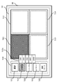
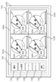
- FIG. 8 is a diagram showing the display unit 50 according to the digital camera 1 of the present embodiment.
- the display unit 50 has a display surface 51.
- the display surface 51 is provided with an image display area 510 and an operation button display area 520.
- the image display area 510 is an area for displaying an image indicated by the image data generated by the imaging unit 20. In the image display area 510, for example, a still image, a moving image, and a live view image are displayed.
- the operation button display area 520 is an area for displaying a menu image 520M for the user to set imaging conditions and the like.
- the image display area 510 and the operation button display area 520 are provided in one display surface 51.
- the image display area 510 is divided into a plurality of display areas so that a plurality of images can be displayed. For example, it is divided into four display areas so as to display each image indicated by the four image data generated by the imaging unit 20.
- the upper left display area is referred to as a first display area 511.
- the upper right display area is referred to as a second display area 512.
- the lower left display area is referred to as a third display area 513.
- the lower right display area is referred to as a fourth display area 514.
- the first display area 511, the second display area 512, the third display area 513, and the fourth display area 514 are display areas having the same display area. Further, the first display area 511, the second display area 512, the third display area 513, and the fourth display area 514 may be display areas having different display areas.
- the display area of the first display area may be larger than the display area of the second display area.
- the display area of the first display area may be larger than the display area of the third display area.
- the display area of the first display area may be larger than the display area of the fourth display area.
- the display area of the second display area may be larger than the display area of the first display area.
- the display area of the second display area may be larger than the display area of the third display area.
- the display area of the second display area may be larger than the display area of the fourth display area.
- the display area of the third display area may be larger than the display area of the first display area.
- the display area of the third display area may be larger than the display area of the second display area.
- the display area of the third display region may be larger than the display area of the fourth display region.
- the display area of the fourth display area may be larger than the display area of the first display area.
- the display area of the fourth display area may be larger than the display area of the second display area.
- the display area of the fourth display area may be larger than the display area of the third display area.
- the first display area 511 is an area for displaying an image (this image is referred to as a first image) indicated by the image data generated in the first imaging area shown in FIG.
- the second display area 512 is an area for displaying an image (this image is referred to as a second image) indicated by the image data generated in the second imaging area shown in FIG.
- the third display area 513 is an area for displaying an image (this image is referred to as a third image) indicated by the image data generated in the third imaging area shown in FIG.
- the fourth display area 514 is an area for displaying an image (this image is referred to as a fourth image) indicated by the image data generated in the fourth imaging area shown in FIG.
- the first imaging area, the second imaging area, the third imaging area, and the fourth imaging area shown in FIG. 5 are arranged uniformly over the entire pixel area 113A, the first image, The second image, the third image, and the fourth image appear to be the same subject image.
- the first imaging area, the second imaging area, the third imaging area, and the fourth imaging area shown in FIG. 5 are imaged under different imaging conditions. Accordingly, the brightness of the subject, the blurring of the subject, the smoothness of the movement of the subject in the moving image, and the like vary depending on the imaging conditions.
- the first image includes a first live view image, a first still image, and a first moving image.
- the second image includes a second live view image, a second still image, and a second moving image.
- the third image includes a third live view image, a third still image, and a third moving image.
- the fourth image includes a fourth live view image, a fourth still image, and a fourth moving image.
- the display unit 50 includes a touch panel 52.
- the touch panel 52 is provided on the display surface 51.
- the first touch area 511 a is formed so as to overlap the first display area 511.
- the second touch area 512 a is formed so as to overlap the second display area 512.
- the third touch area 513a is formed so as to overlap the third display area 513.
- the fourth touch area 514a is formed so as to overlap the fourth display area 514.
- the operation button display area 520 is provided in the vicinity of the image display area 510.
- a menu image 520M is displayed for the user to select a display area, set an imaging condition, an imaging mode, and the like.
- the menu image 520M includes a selection button image 521, an ISO sensitivity button image 522, a shutter speed button image 523, a picture control button image 524, and an imaging mode button image 525.
- the selection button image 521 includes a first image, a second image, a third image, and a fourth image displayed on the first display area, the second display area, the third display area, and the fourth display area, respectively. Used when selecting either one.
- the ISO sensitivity button image 522 is used when the user sets the ISO sensitivity (that is, gain).
- the shutter speed button image 523 is used when the user sets the shutter speed (that is, the exposure time). The shutter speed corresponds to the charge accumulation time.
- the picture control button image 524 is used when the user sets (adjusts) image characteristics such as image tone, hue, and contrast.
- the imaging mode button image 525 is used when the user selects whether to manually set the imaging condition or automatically set the imaging condition.
- the touch area 521a is formed so as to overlap the selection button image 521.
- the touch area 522a is formed so as to overlap the ISO sensitivity button image 522.
- the touch area 523a is formed so as to overlap the shutter speed button image 523.
- the touch area 524a is formed so as to overlap the picture control button image 524.
- the touch area 525a is formed so as to overlap the imaging mode button image 525.
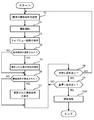
- FIG. 9 is a flowchart for explaining a photographing operation executed by the system control unit 70 of the first embodiment.
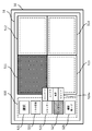
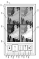
- FIG. 11, FIG. 12, and FIG. 13 are diagrams showing display examples of the display surface 51 in the first embodiment.
- the dividing unit 74 moves in the pixel region 113 ⁇ / b> A of the image sensor 100. , And divided into a plurality of imaging areas (first imaging area, second imaging area, third imaging area, and fourth imaging area) as shown in FIG.
- the setting unit 73 sets predetermined standard imaging conditions for the first imaging region, the second imaging region, the third imaging region, and the fourth imaging region set by the dividing unit 74 (step S1). ).
- the setting unit 73 sets ISO sensitivity (“100”), shutter speed (“1/2 second”), and the like as standard imaging conditions for the first imaging region.
- the setting unit 73 sets ISO sensitivity (“200”), shutter speed (“1/100 second”), and the like as standard imaging conditions for the second imaging region.
- the setting unit 73 sets ISO sensitivity (“400”), shutter speed (“1/500 second”), and the like as standard imaging conditions for the third imaging region.
- the setting unit 73 sets ISO sensitivity (“800”), shutter speed (“1/1000 second”), and the like as standard imaging conditions for the fourth imaging region.
- the system control unit 70 starts a shooting operation (step S2).
- the control unit 71 causes the first display area 511 of the display surface 51 to display the first live view image indicated by the first image data generated in the first imaging area of the imaging device 100.
- the control unit 71 causes the second display area 512 of the display surface 51 to display the second live view image indicated by the second image data generated in the second imaging area of the imaging element 100.
- the control unit 71 displays the third live view image indicated by the third image data generated in the third imaging region of the imaging element 100 in the third display region 513 of the display surface 51.
- the control unit 71 displays the fourth live view image indicated by the fourth image data generated in the fourth imaging region of the imaging device 100 in the fourth display region 514 of the display surface 51 (Step S3).
- the third live view image and the fourth live view image are displayed.
- the first imaging area, the second imaging area, the third imaging area, and the fourth imaging area are imaged under different imaging conditions. Therefore, the first display area 511, the second display area 512, the third display area 513, and the fourth display area 514 have different brightness of the subject, blurring of the subject (moving moving subject), contrast, and the like.
- a view image is displayed.
- the user can display the first live view image, the second live view image, and the second live view image displayed in the first display area 511, the second display area 512, the third display area 513, and the fourth display area 514 of the image display area 510, respectively.
- the user selects any one of the first live view image, the second live view image, the third live view image, and the fourth live view image, the user selects the selection button image 521 (that is, the touch area 521a). Touch with your finger.
- the display area can be selected, that is, the four touch areas (touch area 511a, touch area 512a, touch area 513a, and touch area 514a) of the touch panel 52 can be detected. Thereafter, the user touches any one of the four display areas (the first display area 511, the second display area 512, the third display area 513, and the fourth display area 514) with one finger to display one display area. Select.
- the touch panel 52 outputs a detection signal corresponding to the touch area touched by the user to the system control unit 70.
- the selection unit 72 recognizes the display area selected by the user based on the detection signal from the touch panel 52. In the example shown in FIGS. 11, 12, and 13, the first display area 511 is selected by the user. The selection unit 72 determines whether any of the first display area 511, the second display area 512, the third display area 513, and the fourth display area 514 has been selected by the user (step S4). When it is determined that one of the first display area 511, the second display area 512, the third display area 513, and the fourth display area 514 is selected by the user, the selection unit 72 displays the display selected by the user. An area (first display area 511 in FIG. 11) is set (step S5). Specifically, the selection unit 72 outputs an instruction signal for instructing the driving unit 21 such as the position of a block corresponding to the display area selected by the user.
- the user can change the imaging condition in the selected display area (that is, any one of the first imaging area, the second imaging area, the third imaging area, and the fourth imaging area).
- the setting unit 72 determines whether or not the imaging condition has been changed by the user (step S6).
- the selection unit 72 sets the changed imaging condition (step S7).
- the control unit 71 displays a plurality of ISO sensitivity values next to the ISO sensitivity button image 522. In the example illustrated in FIG. 11, “100”, “200”, “400”, “800”, and “1600” are displayed as the ISO sensitivity.
- the setting unit 73 newly sets a touch area on the touch panel 52 so as to overlap each ISO sensitivity value area. The user touches one of the ISO sensitivity values.
- the touch panel 52 outputs a detection signal corresponding to the touch area touched by the user to the system control unit 70.
- the setting unit 73 sets the ISO sensitivity value touched by the user. Specifically, the setting unit 73 outputs an instruction signal for instructing a gain corresponding to the ISO sensitivity selected by the user to the driving unit 21.
- the user when the user sets the shutter speed (charge accumulation time) as the imaging condition of the first display area 511, the user performs the same operation as the ISO sensitivity setting. That is, the user touches the shutter speed button image 523 (that is, the touch area 523a) when setting the shutter speed as the imaging condition.
- the touch panel 52 outputs a detection signal corresponding to the touch area 523 a touched by the user to the system control unit 70.
- the control unit 71 displays a plurality of shutter speed values next to the shutter speed button image 523.
- the user touches one of the shutter speed values.
- the setting unit 73 sets the shutter speed value touched by the user. Specifically, the setting unit 73 outputs an instruction signal instructing the shutter speed selected by the user to the drive unit 21.
- the user touches the picture control button image 524 (that is, the touch area 524a) when setting the picture control as the imaging condition of the first display area 511.
- the touch panel 52 outputs a detection signal corresponding to the touch area 524a touched by the user to the system control unit 70.
- the control unit 71 displays a plurality of types of picture controls next to the picture control button image 524. In the example shown in FIG. 12, “Standard”, “Neutral”, “Landscape”, and “Vivid” are displayed as the types of picture control. Note that “standard” is adjusted by the image processing unit 30 to a standard image with no bias in the strength, contrast, brightness, color density, and the like of the contour of the subject.
- the image processing unit 30 faithfully reproduces the gradation and color tone specific to the subject and adjusts the image to be the closest to the real subject.
- the image processing unit 30 adjusts a natural landscape, a cityscape, or the like to a high-gradation image with high gradation.
- “Vivid” is adjusted by the image processing unit 30 to a colorful image in which the contour and contrast of the subject are emphasized.
- the setting unit 73 sets a new touch area on the touch panel 52 so as to overlap the area of the picture control type.
- the user touches one of the picture control types.
- the touch panel 52 outputs a detection signal corresponding to the touch area touched by the user to the system control unit 70.
- the setting unit 73 sets the type of picture control touched by the user. Specifically, the setting unit 73 outputs an instruction signal for instructing the type of picture control selected by the user to the image processing unit 30.
- the control unit 71 displays “P”, “S”, “A”, and “M” next to the imaging mode button image 525.
- P means P mode (program auto), and is a mode in which the aperture value and the shutter speed are automatically determined so as to achieve proper exposure.
- S means S mode (shutter priority mode), and is a mode for determining an aperture value that provides appropriate exposure with respect to the shutter speed selected by the user.
- A means A mode (aperture priority mode), and is a mode for automatically determining a shutter speed at which a proper exposure is obtained with respect to the aperture value selected by the user.
- M means M mode (manual mode), in which the user selects an aperture value and a shutter speed.
- the system control unit 70 (setting unit 73) can set different imaging conditions for each block of the imaging region 113A, but the aperture value can be set for each block. First, it is set for the entire imaging region 113A.
- the setting unit 73 newly sets a touch area on the touch panel 52 so as to overlap the area of the type of shooting mode.
- the user touches one of the types of shooting modes.
- the touch panel 52 outputs a detection signal corresponding to the touch area touched by the user to the system control unit 70.
- the setting unit 73 sets the type of shooting mode touched by the user.
- the setting unit 73 automatically determines at least one of the aperture value and the shutter speed so as to achieve an appropriate exposure.
- the setting unit 73 outputs an instruction signal for instructing the shutter speed to the drive unit 21.
- the setting unit 73 outputs control information corresponding to the aperture value to the lens drive control device 15.
- the driving unit 21 receives an instruction signal that instructs the first imaging area corresponding to the first display area 511 selected by the user in units of blocks. Further, the drive unit 21 receives an instruction signal for instructing an imaging condition selected by the user. In response to this, the driving unit 21 drives the imaging unit 20 so as to capture an image with the instructed imaging conditions (shutter speed, ISO sensitivity) in the block corresponding to the first display area 511. Further, the image processing unit 30 receives an instruction signal for instructing an imaging condition selected by the user. In response to this, the image processing unit 30 performs image processing on the RAW data in the first imaging area based on the instructed imaging conditions (control parameters such as white balance, gradation, and tone correction). Further, the lens drive control device 15 adjusts the aperture diameter of the diaphragm 14 based on the control information from the system control unit 70.
- the first live view image displayed in the first display area 511 is changed.
- the ISO sensitivity is increased, the subject is brightly imaged even with a small amount of light. Also, the dark part of the first live view image becomes brighter.
- the shutter speed is increased, blurring of a moving subject is reduced.
- the user selects one of the first display area 511, the second display area 512, the third display area 513, and the fourth display area 514, and sets the imaging condition in the selected display area.
- the live view image that changes in accordance with the change in the imaging condition can be confirmed.
- the imaging condition selected by the user may not be a condition suitable for proper exposure.
- the user can also recognize that the exposure condition is overexposed or underexposed by changing the imaging condition.
- the user can recognize how the live view image changes when the imaging condition is changed. Therefore, the user can take a picture after confirming a plurality of live view images by changing the imaging condition before taking the picture.
- step S8 The processing from step S1 to S7 as described above is repeatedly executed until the user performs a half-press operation (step S8) of the release switch of the operation unit 55. 10, 11, 12, and 13, the case where the user has selected the first display area 511 among the four display areas has been described. However, the user has selected the second display area 512, the second display area 511, and the like. Similar processing is performed when the third display area 513 and the fourth display area 514 are selected.
- the imaging conditions for each area that can be set by the user are not limited to ISO sensitivity, shutter speed, and picture control.
- the frame rate, the thinning rate, the number of added rows or columns to which pixel signals are added, the number of digitized bits, and the like may be set as imaging conditions for each display area.
- parameters such as color signal processing, white balance adjustment, gradation adjustment, and compression rate may be set as imaging conditions for each display area.
- the system control unit 70 determines whether or not the release switch half-press operation (SW1 operation) has been performed (step S8).
- the half-press operation is used as an instruction to start shooting preparation.
- the system control unit 70 performs auto focus (AF) control and the like for automatically performing focus adjustment.
- the system control unit 70 determines whether or not the release switch has been fully pressed (SW2 operation) (step S9). If it is determined that the full-press operation has been performed, the setting unit 73 performs an imaging process that causes the imaging device 100 to perform imaging (step S10). Note that imaging based on the full-press operation in step S10 is referred to as main imaging. In the present embodiment, the imaging unit 20 applies to the pixel region (imaging region) 113A of the imaging element 100 based on the imaging condition in the display region (live view image) last set by the selection unit 72 in step S5. Perform real imaging.
- control unit 71 performs control so that an image (still image) that is actually captured with respect to the pixel region (imaging region) 113 ⁇ / b> A is displayed in all regions of the image display region 510. Thereby, the user can confirm what kind of image was imaged with a large display area.
- each display area (the first display area 511, the second display area 512, the third display area 513, and the fourth display area 514) has an image pickup area (the first image pickup area, the second image pickup area, and the third image pickup area).
- Moving images captured under different imaging conditions are displayed in the imaging area and the fourth imaging area, respectively.
- a button for setting a frame rate is displayed in the operation button display area 520.
- the control unit 71 displays the moving image that is actually captured with respect to the pixel region (imaging region) 113 ⁇ / b> A in all regions of the image display region 510.
- the first image pickup device (a part of the image pickup device 100) that picks up the image under the first image pickup condition and the second image pickup condition that is different from the first image pickup condition are used.
- a plurality of second image sensors (image sensors different from some of the image sensors of the image sensor 100) are arranged, and the first image data and the second image data generated according to the subject image incident on the first image sensor
- An imaging unit 20 that outputs second image data generated according to the subject image incident on the imaging element, and a first image (for example, an image displayed in the first display area 511) indicated by the first image data.
- a second image indicated by the second image data (for example, an image displayed in the second display area 512) is displayed on the display unit 50 so that the recording mode of the first image data and the second image data can be selected.
- a control unit 71 for presenting According to such a configuration, it is possible to confirm a change in a plurality of images corresponding to a change in imaging conditions.
- each of the first image and the second image is a live view image, and includes a selection unit 72 that selects a recording mode of the first image data and the second image data.
- the main imaging is performed under the imaging conditions corresponding to the recording mode selected by the selection unit 72. According to such a configuration, the main imaging can be performed after confirming a plurality of live view images captured under different imaging conditions before starting the actual imaging of a still image or a moving image.
- the selection unit 72 since the selection unit 72 includes the touch panel 52 formed on the display unit 50, the live view image can be selected with a simple operation.
- a dividing unit 74 that divides a plurality of imaging elements of the imaging unit 20 into at least a first imaging element and a second imaging element is provided.
- the control unit 71 can display at least two or more live view images on the display unit 50.
- the dividing unit 74 arranges a plurality of first imaging elements and a plurality of second imaging elements in the imaging region 113A of the imaging unit 20 over the entire surface.
- the image capturing unit 20 can capture a plurality of live view images for a subject image that looks the same for the user. Therefore, the user can easily confirm the difference in the live view image for the subject image due to the difference in the imaging conditions.
- a setting unit 73 that sets the first imaging condition and the second imaging condition is provided. According to such a configuration, it is possible to perform imaging not only with predetermined imaging conditions but also with imaging conditions selected by the user.
- the setting unit 73 varies at least one of the frame rate, the gain, and the exposure time as the imaging condition. According to such a configuration, the user changes the live view image by changing the frame rate, gain, and exposure time (shutter speed) for each of the plurality of imaging regions (multiple live view images). Imaging can be performed after confirming the live view image.
- the setting unit 73 changes at least one of white balance, gradation, and color tone correction as the imaging condition.
- the user changes the live view image by changing the white balance, gradation, and color tone correction for each of the plurality of imaging regions (multiple live view images), and the changed live view. Imaging can be performed after confirming the image.
- the setting unit 73 changes either the exposure time (shutter speed) or the gain (ISO sensitivity) so that the brightness of the first image and the second image are the same. Accordingly, the other of the exposure time and the gain may be changed. Specifically, the setting unit 73 decreases the gain by increasing the exposure time in the first imaging region or the second imaging region so that the first image and the second image have the same appropriate brightness, and the exposure is performed. Shortening the time increases the gain. According to such a configuration, the user can confirm in advance the difference in images due to combinations of different exposure times and gains with the same brightness.
- the digital camera 1 has been described as an example of an electronic device.
- the electronic device is not limited to the digital camera 1 and may be configured by a device such as a smartphone, a mobile phone, or a personal computer having an imaging function.
- the display unit 50 may be provided outside the electronic device.
- each of the system control unit 70 and the display unit 50 is provided with a communication unit that transmits and receives signals (image data, control signals, and the like) by wire or wirelessly.
- the image processing unit 30 and the system control unit 70 may be configured integrally.
- the system control unit having one body side CPU performs the processing based on the control program, thereby taking on the function of the image processing unit 30 and the function of the system control unit 70.
- each display area (the first display area 511, the second display area 512, the third display area 513, and the fourth display area 514) in the image display area 510 are described.
- each display area is divided into a plurality of areas, and different imaging conditions (including accumulation conditions) are set for each divided area.
- FIG. 14 is a diagram illustrating a display unit 50A according to the digital camera 1 of the second embodiment.
- the display surface 51A of the display unit 50A is provided with an image display area 510A and an operation button display area 520, similarly to the display surface 51 shown in FIG.
- the image display area 510A is an area for displaying an image captured by the imaging unit 20, that is, a still image, a moving image, and a live view image.
- the operation button display area 520 is an area for displaying a menu for the user to set imaging conditions and the like.
- the image display area 510A is divided into four display areas (a first display area 516, a second display area 517, a third display area 518, and a fourth display area 519).
- the first display area 516, the second display area 517, the third display area 518, and the fourth display area 519 are the first display area 511, the second display area 512, the third display area 513, and the third display area 513 shown in FIG.
- Each corresponds to the fourth display area 514.
- a plurality of blocks B (i, j) are set in each display area 516, 517, 518, 519.
- a touch panel 52 is provided on the display surface 51A.
- the first touch area 516 a is formed so as to overlap the first display area 516 in the touch panel 52 as in the case shown in FIG. 8.
- the second touch area 517 a is formed so as to overlap the second display area 517.
- the third touch area 518 a is formed so as to overlap the third display area 518.
- the fourth touch area 519a is formed so as to overlap the fourth display area 519.
- the first touch area 516a is divided into a plurality of touch areas P (i, j) corresponding to the plurality of blocks B (i, j).
- the second touch area 517a, the second touch area 518a, and the fourth touch area 519a are also divided into a plurality of touch areas P (i, j) corresponding to the plurality of blocks B (i, j), respectively.
- a detection signal indicating the pressed position is sent to the system control unit 70.
- symbol is attached
- FIG. 15 is a flowchart for explaining a photographing operation executed by the system control unit 70 of the second embodiment.
- FIGS. 16 and 17 are diagrams showing examples of display on the display surface 51A in the second embodiment.
- the digital camera 1 can shoot still images and moving images, the case of shooting still images will be described.
- step S1 to S5 shown in FIG. 15 is the same as the processing from step S1 to S5 shown in FIG.
- the user selects any one of the first display area 516, the second display area 517, the third display area 518, and the fourth display area 519 (see Steps S4 and S5), and then within the selected display area. It is possible to select a region.
- the user selects an area in one display area, the user touches (or traces) the block B (i, j) set in the display area with a finger. Select an area in blocks.
- the touch panel 52 outputs a detection signal corresponding to the touch area P (i, j) touched by the user to the system control unit 70.
- the selection unit 72 recognizes the area selected by the user based on the detection signal from the touch panel 52.
- the first display area 516 is selected by the user.
- the area 516A in the first display area 516 is selected by the user.
- This area 516A is the background area behind the waterfall (the area where the white line in FIG. 16 is drawn).
- the area 516A includes blocks B (3, 1), B (4, 1), B (5, 1), B (6, 1), B (7, 1), B (8, 1). ), B (4,2), B (5,2), B (6,2), B (7,2), B (8,2), B (5,3), B (6,3) , B (7, 3), B (8, 3), B (6, 4), B (7, 4), B (8, 4).
- the selection unit 72 determines whether or not an area has been selected by the user (step S11). If it is determined that the area has been selected by the user, the selection unit 72 sets the area 516A selected by the user (step S12). Specifically, the selection unit 72 outputs an instruction signal for instructing the drive unit 21 of the position of the block selected by the user.
- the user can change the imaging condition in the selected display area (that is, any one of the first imaging area, the second imaging area, the third imaging area, and the fourth imaging area).
- the user can also change the imaging condition in the area within the selected display area.
- the setting unit 72 determines whether or not the imaging condition has been changed by the user (step S14). When the selection unit 72 determines that the imaging condition has been changed by the user, the selection unit 72 sets the changed imaging condition (step S15).
- the control unit 71 displays a plurality of ISO sensitivity values next to the ISO sensitivity button image 522.
- the setting unit 73 newly sets a touch area on the touch panel 52 so as to overlap each ISO sensitivity value area.
- the user touches one of the ISO sensitivity values.
- the touch panel 52 outputs a detection signal corresponding to the touch area touched by the user to the system control unit 70.
- the setting unit 73 sets the ISO sensitivity value touched by the user. Specifically, the setting unit 73 outputs an instruction signal for instructing a gain corresponding to the ISO sensitivity selected by the user to the driving unit 21.
- the driving unit 21 receives an instruction signal that instructs the first imaging area corresponding to the first display area 516 selected by the user in units of blocks. Further, the drive unit 21 receives an instruction signal instructing the area 516A in the first display area 516 selected by the user in units of blocks. Further, the drive unit 21 receives an instruction signal for instructing an imaging condition selected by the user. In response to this, the driving unit 21 drives the imaging unit 20 so as to capture an image with the instructed imaging conditions (shutter speed, ISO sensitivity) in the block corresponding to the region 516A of the first display region 516.
- the image processing unit 30 When the image processing unit 30 receives an instruction signal instructing the imaging condition selected by the user, the image processing unit 30 is based on the instructed imaging condition (control parameters such as white balance, gradation, and tone correction). Image processing is executed on the RAW data in the area corresponding to the area 516A. Further, the lens drive control device 15 adjusts the aperture diameter of the diaphragm 14 based on the control information from the system control unit 70.
- the image of the region 516A in the first live view image changes.
- the ISO sensitivity is increased, the subject is brightly imaged even with a small amount of light. Further, the dark part of the region 516A becomes brighter.
- the shutter speed is increased, blurring of a moving subject is reduced.
- the user selects one of the first display area 516, the second display area 517, the third display area 518, and the fourth display area 519, and further selects an area within the selected display area. Then, the user sets imaging conditions in the selected area. Thereby, the image of the predetermined area
- steps S1 to S5 and the processes from S11 to S14 as described above are repeatedly executed until the user half-presses the release switch (step S8) of the operation unit 55.
- the case where the user selects the area 516 ⁇ / b> A of the first display area 516 has been described. However, the same processing is performed when the user selects another area of the first display area 516. Is called.
- the region 516B other than the region 516A is selected from the first display region 516. Then, the image displayed in the area 516B in the first display area 516 changes according to the selection of the ISO sensitivity button image 522, the shutter speed button image 523, the picture control button image 524, and the like by the user.
- step S8 to S10 are executed. These processes are the same as those described with reference to FIG.
- each display area includes each image pickup area (the first image pickup area, the second image pickup area, and the third image pickup area).
- Moving images captured under different imaging conditions are displayed in the imaging area and the fourth imaging area, respectively.
- a button for setting a frame rate is displayed in the operation button display area 520.
- the control unit 71 displays the moving image that is actually captured with respect to the pixel region (imaging region) 113 ⁇ / b> A in all regions of the image display region 510.
- the setting unit 73 causes the imaging conditions of a part of the first imaging element or the second imaging element to be different from the first imaging condition or the second imaging condition.
- the imaging condition is changed for each area in the first display area 516, the second display area 517, the third display area 518, and the fourth display area 519. It becomes possible to do. Therefore, the user can create an image by changing the imaging conditions for each region before starting to capture a still image or a moving image. It can be said that such processing performs editing before imaging of an image.
- the imaging conditions for each area that can be set by the user are not limited to ISO sensitivity, shutter speed, and picture.
- the above-described frame rate, thinning rate, the number of added rows or columns to which pixel signals are added, the number of digitized bits, and the like may be set as imaging conditions for each region.
- parameters such as color signal processing, white balance adjustment, gradation adjustment, and compression rate may be set as imaging conditions for each region.
- the live view image is displayed in the four display areas of one display unit 50.
- two display units are provided and two live view images or still images are displayed on one of the two display units.
- a live view image obtained by combining two live view images or a still image is displayed on the other display unit.
- FIG. 18 is a functional block diagram of the image processing unit 30A and the system control unit 70 according to the digital camera 1 of the third embodiment.
- FIG. 18 shows only the configuration corresponding to the image processing unit 30 and the system control unit 70 among the configurations shown in FIG.
- the image processing unit 30 ⁇ / b> A includes a synthesis unit 32 in addition to the image generation unit 31.
- the synthesizing unit 32 synthesizes the image data of the first imaging area and the image data of the second imaging area captured under different imaging conditions.
- the third embodiment unlike the case described in the first embodiment and the second embodiment (array pattern shown in FIG. 5), only the first imaging region and the second imaging region are set in the pixel region 113A. ing.
- an odd-numbered row (2n-1) block in an odd-numbered column (2m-1) and an even-numbered row (2n) block in an even-numbered column (2m) The first imaging area is configured as described above.
- the second imaging region is configured by blocks of odd rows (2n-1) in even columns (2m) and blocks of even rows (2n) in odd columns (2m-1). That is, the dividing unit 74 divides each block in the pixel region 113A so as to have a checkered pattern.
- FIG. 19 is a diagram illustrating a display example when images are displayed on the first display unit 50B and the second display unit 53 in the third embodiment.
- the first display unit 50B is a display panel having a square display surface.
- the first display unit 50B is provided on the back surface of the digital camera 1.
- the first touch panel is formed on the display surface of the first display unit 50B.
- the second display unit 53 is a display panel having a square display surface. An end portion of the second display portion 53 is rotatably connected by a hinge (not shown) provided on the back surface of the digital camera 1 and below the first display portion 50B. As the second display unit 53 rotates with the hinge as a fulcrum, the first display unit 50B is opened and closed by the second display unit 53.
- the release switch 55a is a switch that is pressed by the user when capturing a still image.
- the mode dial 55b is a dial rotated by the user when setting various scene modes such as portrait, landscape, and night view.
- the moving image switch 55c is a switch pressed by the user when capturing a moving image.
- a multi-selector 55d is provided on the back of the digital camera 1 and on the side of the first display unit 50B.
- the multi-selector 55d is a key for the user to select a menu (menu for setting the shooting mode) displayed on the first display unit 50B or the second display unit 53 using the up / down / left / right arrow keys and the OK switch. And a switch.
- the operation unit 55 includes a release switch 55a, a mode dial 55b, a moving image switch 55c, and a multi selector 55d. Note that the operation unit 55 may include other switches.
- the control unit 71 displays a live view image or a still image (an image of a person captured at night) in the first imaging region in the left region 53 ⁇ / b> L of the display surface of the second display unit 53.
- the control unit 71 displays a live view image or a still image of the second imaging region in the right region 53R of the display surface of the second display unit 53.
- the control unit 71 combines a live view image or still image of the first imaging region with a live view image or still image of the second imaging region. Display the image.
- HDR High Dynamic
- Range imaging is widely known.
- HDR imaging a plurality of images are captured while changing imaging conditions (for example, exposure), and the images are combined to generate an image with less overexposure and underexposure.
- imaging conditions for example, exposure
- the subject moves or the user (photographer) moves the digital camera 1. There is. In this case, since the plurality of images are not the same subject image, it is difficult to synthesize the images.
- the imaging time of two images (live view images or still images) with different imaging conditions can be set to the same time (or substantially the same time). Therefore, the configuration of the third embodiment can solve the problems of conventional HDR imaging.
- the HDR mode is configured to be selectable according to the operation of the multi selector 55d by the user.
- the user can capture the first live view image or the first still image in the first imaging area and the second live view image or the second still image in the second imaging area that are captured under different imaging conditions. Can be confirmed before imaging, and a live view image or still image with a wide dynamic range obtained by combining the first live view image or still image and the second live view image or still image is also confirmed before imaging. be able to.
- the combining unit 32 generates image data with a wide dynamic range by combining the image data of the first imaging region and the image data of the second imaging region.
- the composition unit 32 is not limited to such a configuration, and the combining unit 32 generates image data in which the edge (contour) of the subject is emphasized by combining the image data of the first imaging region and the image data of the second imaging region.
- the setting unit 73 sets the shutter speed of the first imaging area to 1/30 seconds, and sets the shutter speed of the second imaging area to 1/200 seconds. In this case, when the imaging device 100 captures a fast moving subject, the image data of the first image generated by the first imaging region of the imaging device 100 becomes image data with a large subject blur.
- the image data generated by the second imaging region is image data with less subject blurring.
- the synthesizer 32 adds the image data of the edge portion of the subject in the image data of the second image to the image data of the first image and synthesizes it. Thereby, image data in which the edge portion of the moving subject is emphasized is generated.
- the control unit 71 displays a live view image or a still image of the first imaging region in the left region 53L of the display surface of the second display unit 53.
- the control unit 71 displays a live view image or a still image of the second imaging region in the right region 53R of the display surface of the second display unit 53.
- the control unit 71 combines a live view image or still image of the first imaging region with a live view image or still image of the second imaging region.
- the image (a composite image in which the edge portion of the subject is emphasized) is displayed. According to such a configuration, the user can check images captured at different shutter speeds, and can also check a composite image obtained by combining these images.
- the control unit 71 controls the first display area 511, the second display area 512, the third display area 513, and the fourth display area 514 (or the first display). Area 516, second display area 517, third display area 518, and fourth display area 519), the first live view image, the second live view image, the third live view image, and the fourth live view image are displayed, respectively. It was controlled to do.
- the control unit 71 controls the first moving image, the second moving image, the third moving image, and the fourth moving image in the first display area, the second display area, the third display area, and the fourth display area, respectively. Control to display 4 videos.
- the display unit displays each moving image at a refresh rate (a value indicating how much refreshing per unit time) according to the frame rate of the first moving image, the second moving image, the third moving image, and the fourth moving image. .
- FIG. 20 is a diagram showing a display example of the display surface 51C in the fourth embodiment.
- a frame rate button image 545 for setting a frame rate is displayed in the operation button display area 540.
- This frame rate button image 545 is also included in the menu image 540M.
- the selection button image 541, the ISO sensitivity button image 542, the shutter speed button image 543, and the picture control button image 544 are the selection button image 521, the ISO sensitivity button image 522, the shutter speed button image 523 shown in FIG. And the picture control button image 524.
- a frame rate button image 545 is provided instead of the imaging mode button image 525 shown in FIG.
- FIG. 20 is a diagram showing a display example of the display surface 51C in the fourth embodiment.
- the first display area 531, the second display area 532, the third display area 533, and the fourth display area 534 are respectively the first display area 511 and the first display area 511 shown in FIG. This corresponds to the second display area 512, the third display area 513, and the fourth display area 514.
- the setting unit 73 performs different frames in the first imaging region, the second imaging region, the third imaging region, and the fourth imaging region of the image sensor 100 according to the operation of the frame rate button image 545 by the user or automatically.
- Set the rate For example, the setting unit 73 sets the frame rate of the first imaging area to 30 fps, sets the frame rate of the second imaging area to 60 fps, sets the frame rate of the third imaging area to 90 fps, and sets the fourth imaging area. Is set to 120 fps. Then, the setting unit 73 captures moving images at different frame rates in the first imaging region, the second imaging region, the third imaging region, and the fourth imaging region of the image sensor 100 according to the operation of the moving image switch by the user. Let it run.
- the control unit 71 includes a first imaging area, a second imaging area, and a third imaging area in the first display area 531, the second display area 532, the third display area 533, and the fourth display area 534 of the image display area 530, respectively. Moving images captured at different frame rates are displayed in the area and the fourth imaging area.
- images are refreshed (updated) at the same refresh rate on the display surface.
- the display unit 50C is configured to be refreshable at different refresh rates in the first display area 531, the second display area 532, the third display area 533, and the fourth display area 534 of the display surface 51C. ing.
- a drive circuit that drives refresh of the pixels and a drive circuit that drives refresh of each pixel in the fourth display region 534 are provided separately. According to such a configuration, the user can easily recognize the difference between a plurality of moving images captured at different frame rates.
- the control unit 71 also includes a first moving image, a second moving image, a third moving image, and a first moving image captured at different frame rates in the first imaging region, the second imaging region, the third imaging region, and the fourth imaging region of the image sensor 100. Control is performed so that the image data of the fourth moving image is separately recorded in the recording unit 60. According to such a configuration, image data of a plurality of moving images captured at different frame rates can be recorded in the recording unit 60 at the same time.
- the control unit 71 is different in the first display area, the second display area, the third display area, and the fourth display area on the display surface.
- the live view image and the moving image captured under the imaging conditions are displayed.
- the still image captured under different imaging conditions may be displayed.
- the control unit 71 displays the first still image, the second still image, the third still image, and the fourth still image captured by one imaging operation of the release switch by the user as the first display area and the first still image, respectively. Control is performed to display in the second display area, the third display area, and the fourth display area.
- the system control unit 70 uses an electronic zoom (also referred to as digital zoom) in any one of the first display area, the second display area, the third display area, and the fourth display area.
- the enlarged display is performed, the enlarged display of the image is also performed in other display areas in accordance with the enlarged display of the image.
- the user performs, for example, a touch operation on the touch panel on the display surface when performing an enlarged display of the image by electronic zoom.
- the control unit 71 outputs to the image processing unit 30 an instruction signal for instructing a region to cut out an image in response to a touch operation on the touch panel by the user.
- the image processing unit 30 performs a process (trimming process) of cutting out image data in an area designated by the system control unit 70.
- the control unit 71 controls the display unit to output the image data of the region cut out by the image processing unit 30 and enlarge and display an image based on the image data of the region on the display surface of the display unit.
- FIG. 21 is a diagram showing a display example of the display surface 51D when the electronic zoom is performed in the fifth embodiment.
- the first display area 511D, the second display area 512D, the third display area 513D, and the fourth display area 514D are respectively the first display area 511 shown in FIG. , Corresponding to the second display area 512, the third display area 513, and the fourth display area 514.
- the operation button display area 520 is the same as the operation button display area shown in FIG.
- the user forms on the first display area 511D in order to enlarge and display the image O1 of the person displayed in the area 516D in the first display area 511D by electronic zoom.
- the touch panel is touched to select the area 516D.
- the control unit 71 causes the person image O1 displayed in the area 516D in the first display area 511D to be enlarged and displayed in the entire area of the first display area 511D.
- the control unit 71 also displays the person image O1 in the second display area 512D, the third display area 513D, and the fourth display area 514D at the same display magnification as the enlarged display of the person image O1 in the first display area 511D. Zoom in.
- control unit 71 enlarges and displays the person image O1 displayed in the area 517D in the second display area 512D in the entire area of the second display area 512D.
- control unit 71 enlarges and displays the image O1 of the person displayed in the area 518D in the third display area 513D in the entire area of the third display area 513D.
- control unit 71 enlarges and displays the image O1 of the person displayed in the area 519D in the fourth display area 514D in the entire area of the fourth display area 514D.
- the control unit 71 performs reduction display of an image by electronic zoom in any one of the first display area 511D, the second display area 512D, the third display area 513D, and the fourth display area 514D.
- the reduced display of the image can be performed in another display area.
- the user is formed on the first display area 511D in order to perform a reduced display of the person image O1 displayed in the entire area of the first display area 511D by electronic zoom.
- the touch panel is touched to select the entire first display area 511D.
- the control unit 71 reduces and displays the person image O1 displayed in the entire area of the first display area 511D in the area 516D of the first display area 511D.
- the control unit 71 also displays the person image O1 in the second display area 512D, the third display area 513D, and the fourth display area 514D at the same display magnification as the reduced display of the person image O1 in the first display area 511D. Zoom out.
- the control unit 71 causes the display unit 50D to display the first image (for example, the person image O1 displayed in the first display region 511D) and the second image (for example, the second image).
- the first image for example, the person image O1 displayed in the first display region 511D
- the second image for example, the second image
- the other of the first image and the second image is enlarged or reduced.
- the user when the user enlarges or reduces the image by electronic zoom, the size of the image displayed in each display area can be matched, and each of the images caused by the difference in imaging conditions can be adjusted. Differences in images can be easily recognized.
- the user does not need to perform an enlargement or reduction operation for each image, and the operation effort of the user is not increased.
- the configuration is not limited to the configuration in which the user performs the electronic zoom by performing a touch operation on the touch panel, and the user operates an electronic zoom switch (for example, a switch operated when the electronic zoom is performed) of the operation unit 55.
- the electronic zoom may be executed.
- FIG. 22 is a diagram illustrating a display example of the display surface 51E in the sixth embodiment.
- the first display area 511E, the second display area 512E, the third display area 513E, and the fourth display area 514E are respectively the first display area 511 shown in FIG. , Corresponding to the second display area 512, the third display area 513, and the fourth display area 514.
- the operation button display area 520 is the same as the operation button display area shown in FIG.
- the control unit 71 includes a first image, a second image, a third image, and a fourth image in the first display area 511E, the second display area 512E, the third display area 513E, and the fourth display area 514E.
- the imaging conditions of these images are displayed on top of the four images.
- “100” is set as the ISO sensitivity
- “1/2 second” is set as the shutter speed
- “Standard” is set as the picture control
- the shooting mode is set as the imaging condition of the first image.
- FIG. 22 the shooting mode is set as the imaging condition of the first image.
- the second image capturing condition “200” is set as the ISO sensitivity, “1/100 second” is set as the shutter speed, “standard” is set as the picture control, and “P” is set as the shooting mode. Indicates the set state. Further, as the imaging condition of the third image, “400” is set as the ISO sensitivity, “1/500 seconds” is set as the shutter speed, “standard” is set as the picture control, and “P” is set as the shooting mode. Indicates the set state. Further, as the imaging condition of the fourth image, “800” is set as the ISO sensitivity, “1/1000 second” is set as the shutter speed, “standard” is set as the picture control, and “P” is set as the shooting mode. Indicates the set state. According to such a configuration, the user can easily confirm the imaging conditions currently set in each display area.
- an imaging condition display area for displaying the imaging conditions currently set in the display area (for example, the first display area) selected by the user may be provided below the display surface of the display unit.
- the control unit 71 may be configured to display the imaging conditions for a predetermined time.
- a switch switch of the operation unit 55 or a switch on the touch panel
- the control unit 71 performs imaging of the imaging condition display region 550 according to the operation of the switch. It may be configured to control display or non-display of conditions.
- buttons 521, 522, 523, 524, 525 are arranged in a predetermined order. That is, the selection button image 521 is arranged at the top, the ISO sensitivity button image 522 is arranged second from the top (that is, below the selection button image 521), and the shutter speed button image 523 is third from the top (that is, ISO).
- the picture control button image 524 is arranged at the fourth position from the top (that is, below the shutter speed button image 523), and the imaging mode button image 525 is arranged at the bottom.
- the control unit 71 changes the arrangement of the buttons 521, 522, 523, 524, and 525 according to the subject in the display area and displays them. Moreover, in 7th Embodiment, the control part 71 displays a button with a high priority in the display mode different from the display mode of another button.
- FIG. 23 is a diagram showing a display example of the display surface 51F in the seventh embodiment.
- the selection button image 521 is arranged at the top
- the shutter speed button image 523 is arranged second from the top (that is, below the selection button image 521)
- the image 524 is arranged third from the top (ie, below the shutter speed button image 523)
- the ISO sensitivity button image 522 is arranged fourth from the top (ie, below the picture control button image 524). Is located at the bottom.
- the shutter speed button image 523 is a button having a larger area than the other buttons (selection button image 521, ISO sensitivity button image 522, picture control button image 524, imaging mode button image 525). It has become.
- the touch area 521a is formed so as to overlap the selection button image 521.
- the touch area 523a is formed so as to overlap the shutter speed button image 523.
- the touch area 524a is formed so as to overlap the picture control button image 524.
- the touch area 522a is formed to overlap the ISO sensitivity button image 522.
- the touch area 525a is formed so as to overlap the imaging mode button image 525. Note that the touch area 523a is larger than the area of other buttons in accordance with the size of the area of the shutter speed button image 523.
- the system control unit 70 instructs the image processing unit 30 to detect the moving subject.
- the image processing unit 30 detects a moving subject and a non-moving subject by comparing a plurality of image data obtained in a time series from the live view image. Then, the image processing unit 30 outputs the detection result to the system control unit 70 together with the image data.
- the control unit 71 determines whether a moving subject is included in the display area selected by the selection unit 72 based on the detection result of the image processing unit 30. When it is determined that the moving subject is included in the display area selected by the selection unit 72, the control unit 71, as shown in FIG. 23, a shutter speed button image that is a button for setting the shutter speed. 523 is displayed at the second position from the top. In addition, the control unit 71 displays the shutter speed button image 523 larger than the other buttons.
- the way the moving subject is captured changes due to the change in shutter speed. For example, when the moving subject is a waterfall, by increasing (fastening) the shutter speed, the image of the waterfall waterfall stops instantaneously. On the other hand, by lowering (slowing) the shutter speed, an image in which the waterfall water flow looks like a thread is obtained. Thus, for a moving subject, the shutter speed has a greater effect on how the subject is photographed than in other imaging conditions. Accordingly, when the moving subject is included in the area, the control unit 71 determines that the shutter speed priority is higher than other imaging conditions. Then, the control unit 71 moves the position of the shutter speed button image 523 upward and displays the shutter speed button image 523 as a button in a large area.
- a button with a high priority is arrange
- a button with a higher priority that is, an imaging condition
- the user can be prompted to operate a button with a higher priority.
- the control unit 71 changes the button arrangement and the display mode (size) depending on whether or not the subject in the area is a moving subject.
- the configuration is not limited to this.
- the system control unit 70 instructs the image processing unit 30 to detect the brightness of the image.
- the image processing unit 30 detects the brightness of the image in the region based on the live view image. Then, the image processing unit 30 outputs the detection result to the system control unit 70 together with the image data.
- the control unit 71 determines whether the brightness of the image in the area selected by the selection unit 72 is a value within a predetermined range based on the brightness detection result by the image processing unit 30. When the controller 71 determines that the brightness of the image in the area is not a value within the predetermined range, the controller 71 displays an ISO sensitivity button image 522 that is a button for setting the ISO sensitivity at the second position from the top. Further, the control unit 71 displays the ISO sensitivity button image 522 larger than the other buttons.
- the control unit 71 determines that the priority of the ISO sensitivity is higher than other imaging conditions when the image in the region is not a value within the predetermined range. Then, the control unit 71 moves the position of the ISO sensitivity button image 522 upward and displays the ISO sensitivity button image 522 as a button in a large area.
- a button with a high priority is arrange
- a button with a higher priority that is, an imaging condition
- the user can be prompted to operate a button with a higher priority.
- a display mode that makes a high-priority button stand out a display mode that changes the color of the button or blinks the button in addition to increasing the button may be used.
- a plurality of imaging condition values may be displayed beside the button to make the button with a high priority stand out.
- positioning of a button may be sufficient, and the structure which changes only the display mode of a button may be sufficient.
- the arrangement of the buttons may be changed to change the display mode of the buttons.
- the user selects the display area after pressing the selection button image 521.
- the user presses the shooting mode button image 525 to select the manual mode as the shooting mode.
- the user changes the imaging condition for each display area.
- the control unit 71 arranges the selection button image 521 at the top and enlarges the selection button image 521.
- the control unit 71 arranges the shooting mode button image 525 at the top and enlarges the shooting mode button image 525.
- control unit 71 arranges any one of the ISO sensitivity button image 522, the shutter speed button image 523, and the picture control button image 524 according to the subject (image) for each display area, and further, Increase the top button.
- the convenience of operation by the user is improved by changing the arrangement and display mode of the buttons in the order according to the user's operation procedure.
- the first curtain sync means that the flash is emitted at the same time as the shutter curtain is fully opened.
- flashing the flash just before the shutter curtain starts closing is called rear curtain synchronization.
- the setting unit 73 sets a slow shutter speed (for example, 1/2 second) for the first imaging region and the second imaging region.
- the system control unit 70 causes the strobe 90 to emit light immediately before ending the charge accumulation in the first imaging region. That is, in the first imaging area, imaging is performed with rear curtain synchronization.
- the system control unit 70 causes the strobe 90 to emit light simultaneously with the start of charge accumulation in the second imaging region. That is, in the second imaging area, imaging is performed with front curtain synchronization.
- FIG. 24 is a timing chart showing the light emission timing of the strobe 90 and the charge accumulation timing in the eighth embodiment.
- the setting unit 73 accumulates charges in the first imaging region from timing t1 before the timing t2 when the strobe 90 starts light emission to timing t3 when the amount of light emitted by the strobe 90 disappears. Let it begin.
- the setting unit 73 starts charge accumulation in the second imaging region from timing t2 when the strobe 90 starts to emit light to timing t4 after the timing t3 when the amount of light from the strobe 90 disappears.
- the control unit 71 displays the first image indicated by the image data generated in the first imaging area on the first display area 511, and displays the second image indicated by the image data generated in the second imaging area. Displayed in the second display area 512.
- the user can confirm in advance how the first image taken with the trailing curtain sync differs from the second image taken with the leading curtain sync.
- the first curtain sync the light and the afterimage of the car light and car as the subject remain in front of the car. Therefore, the image is as if the car is moving backward while the car is moving forward.
- the light of the car and the light trail and the afterimage are images that appear naturally behind the car.
- the digital camera 1 in the first embodiment is separated into an imaging device 1A and an electronic device 1B.
- FIG. 25 is a block diagram illustrating a configuration of the imaging device 1A and the electronic device 1B according to the ninth embodiment.
- the imaging apparatus 1A is an apparatus that captures an image of a subject.
- the imaging apparatus 1A includes a lens unit 10, an imaging unit 20, an image processing unit 30, a work memory 40, an operation unit 55, a recording unit 60, and a first system control unit 70A.
- the configurations of the lens unit 10, the imaging unit 20, the image processing unit 30, the work memory 40, the operation unit 55, and the recording unit 60 are the same as those illustrated in FIG. Accordingly, the same components are denoted by the same reference numerals, and redundant description is omitted.
- the electronic device 1B is a device that displays images (still images, moving images, live view images).
- the electronic apparatus 1B includes a display unit 50 and a second system control unit (control unit) 70B.
- the configuration of the display unit 50 in the electronic device 1B is the same as the configuration illustrated in FIG. Accordingly, the same components are denoted by the same reference numerals, and redundant description is omitted.
- the first system control unit 70A includes a first communication unit 75A.
- the second system control unit 70B has a second communication unit 75B.
- the first communication unit 75A and the second communication unit 75B transmit and receive signals to each other in a wired or wireless manner.
- the first system control unit 70A receives the second image data (the image data image-processed by the image processing unit 30 and the image data recorded in the recording unit 60) via the first communication unit 75A. It transmits to the communication part 75B.
- the second system control unit 70B causes the display unit 50 to display the image data received by the second communication unit 75B. Further, the second system control unit 70B causes the second display unit 53 to display a preset menu image.
- the second system control unit 70B performs control to change the imaging condition (including the accumulation condition) according to the touch operation of the touch panel 52 by the user or automatically.
- the second system control unit 70B performs control to select each display area in the image display area 510 in response to a touch operation on the touch panel 52 by the user or automatically.
- the first system control unit 70A executes imaging control in accordance with an operation of an operation unit (an operation unit that instructs to start capturing a still image or a moving image provided on the electronic device 1B side) 55 by the user.
- 7 may be provided in any one of the first system control unit 70A and the second system control unit 70B (the control unit 71, the selection unit 72, the setting unit 73, and the division unit 74). 7 may be provided in the first system control unit 70A or the second system control unit 70B, and a part of the configuration shown in FIG. 7 is provided in the first system control unit 70A. 7 may be provided in the second system control unit 70B.
- the imaging apparatus 1A includes, for example, a digital camera, a smartphone, a mobile phone, and a personal computer having an imaging function and a communication function
- the electronic device 1B includes, for example, a smartphone, a mobile phone, and a portable personal computer that have a communication function. Consists of a portable terminal such as a computer.
- the first system control unit 70A shown in FIG. 25 is realized by the body side CPU executing processing based on the control program. Further, the second system control unit 70B illustrated in FIG. 25 is realized by the body side CPU executing processing based on the control program.
- a plurality of live view images captured by the imaging device 1A using a mobile terminal such as a smartphone are confirmed. Imaging can be performed.
- the image processing unit 30 and the first system control unit 70A may be configured integrally.
- a system control unit having one body side CPU performs processing based on the control program, thereby taking on the function of the image processing unit 30 and the function of the first system control unit 70A.
- the arrangement of the color filters 102 is a Bayer arrangement, but may be an arrangement other than this arrangement.
- the number of pixels forming the unit group 131 only needs to include at least one pixel.
- the block only needs to include at least one pixel. Therefore, it is possible to execute imaging under different imaging conditions for each pixel.
- part or all of the configuration of the drive unit 21 may be mounted on the imaging chip 113, or part or all of the configuration may be mounted on the signal processing chip 111. Further, a part of the configuration of the image processing unit 30 may be mounted on the imaging chip 113 or the signal processing chip 111. Further, a part of the configuration of the system control unit 70 may be mounted on the imaging chip 113 or the signal processing chip 111.
- the imaging condition (including the accumulation condition) is changed after the user selects the display area.
- the imaging condition is changed.
- a display area that reflects imaging conditions may be selected.
- the control unit 71 erases the display area (live view image) selected by the user from the four display areas on the display panel 51 from the display panel 51. You may make it do. According to such a configuration, it is possible to easily compare the live view image desired by the user by deleting the live view image under the imaging condition that the user does not want to capture. Further, when the display area (live view image) selected by the user is deleted from the display panel 51, the control unit 71 displays the live view image combined by the combining unit 32 in the space of the deleted display area. Also good.
- the imaging unit 20 in response to one full-press operation, captures images for all the regions (all pixels) of the pixel region 113A under the imaging conditions of the display region selected by the user. Was configured to do. However, not limited to such a configuration, the imaging unit 20 selects one of the divided imaging regions (for example, the first imaging region) among the pixel regions 113A by the user in response to one full-press operation.
- a configuration may be used in which imaging is performed under the imaging conditions of the displayed area. Further, the user may be able to select two or more display areas.
- the imaging unit 20 selects two or more divided imaging areas (for example, the first imaging area and the second imaging area) in the pixel area 113A according to one full-press operation.
- a configuration may be employed in which imaging is performed simultaneously under imaging conditions of two or more display areas.
- each imaging region in the pixel region 113A is composed of a plurality of different blocks. Accordingly, the image generation unit 31 can also generate one live view image for all the pixels in the pixel region 113A by superimposing the live view images captured in the respective imaging regions. Then, the control unit 71 may display the live view image generated by the image generation unit 31 on the display panel 51 (image display area 510).
- the display areas 511, 512, 513, and 514 (or the display areas 516, 517, 518, and 519) in the image display area 510 are display areas having the same area, but are display areas having different areas. Also good.
- the operation button display area 520 is provided in the vicinity of the image display area 510, but may be provided in a position that is not in the vicinity of the image display area 510. Further, the operation button display area 520 may be disposed at a position overlapping the image display area 510. Further, instead of the user touching the touch panel 52, the operation unit 55 may be operated.
- the imaging condition of the live view image selected by the user is the same as the imaging condition when imaging is performed according to the full-press operation of the release switch or the like. . This is because an image actually captured in the live view image can be confirmed.
- the imaging condition of the live view image may be different from the imaging condition of the actually captured image. In this case, the imaging condition is changed to such an extent that the user can recognize the actually captured image based on the live view image.
- the dividing unit 74 defines the imaging region 113 ⁇ / b> A of the imaging device 100 as the first imaging region, the second imaging region, the third imaging region, and the fourth imaging region. It was divided into. However, the dividing unit 74 may divide into two areas of the first imaging area and the second imaging area, and divides into three areas of the first imaging area, the second imaging area, and the third imaging area. Alternatively, it may be divided into five or more imaging regions. In this case, the display area is provided in the image display area of the display unit in accordance with the number of imaging areas divided by the dividing unit 74.
- the dividing unit 74 divides into two imaging regions, two display regions (first display region and second display region) are provided in the image display region, and the dividing unit 74 divides into five or more imaging regions. In such a case, five or more display areas are provided in the image display area.
- the sizes of the first display area, the second display area, the third display area, and the fourth display area in the image display area are fixed.
- an image display is performed. You may comprise so that the magnitude
- the user performs an operation (pinch-out operation) of moving the finger away after the first display area is pinched with the finger, for example.
- the control unit 71 performs control so that the first display area is enlarged and displayed.
- control unit 71 performs control so that the second display area, the third display area, and the fourth display area are automatically reduced and displayed in accordance with the enlarged display of the first display area. According to such a configuration, it is possible to enlarge a user's most desired view (display area displaying an image of interest).
- the control unit 71 performs control so that the first display area is reduced and displayed.
- the control unit 71 controls to automatically enlarge and display the second display area, the third display area, and the fourth display area in accordance with the reduced display of the first display area. According to such a configuration, it is possible to reduce a display area displaying an image that is not focused on by the user.
- the control unit 71 is configured to enlarge or reduce the display area according to the user's operation, but automatically enlarges the display area for displaying the image captured under the recommended imaging conditions.
- Another display area may be configured to be automatically reduced in accordance with the size of the enlarged display area.
- the display units 50, 50A, 50B, 50C, 50D, 50E, and 50F are not limited to the case where the display units 50, 50A, 50B, 50C, 50D, 50E, and 50F are configured with liquid crystal displays that control the transmission of the backlight by applying a voltage.
- an organic electroluminescence type liquid crystal display that controls spontaneous light emission by applying a voltage to control display of each pixel may be used.
Landscapes
- Engineering & Computer Science (AREA)
- Multimedia (AREA)
- Signal Processing (AREA)
- Physics & Mathematics (AREA)
- Power Engineering (AREA)
- Microelectronics & Electronic Packaging (AREA)
- Electromagnetism (AREA)
- Condensed Matter Physics & Semiconductors (AREA)
- General Physics & Mathematics (AREA)
- Computer Hardware Design (AREA)
- Spectroscopy & Molecular Physics (AREA)
- Studio Devices (AREA)
- Transforming Light Signals Into Electric Signals (AREA)
- Exposure Control For Cameras (AREA)
- Camera Bodies And Camera Details Or Accessories (AREA)
- Indication In Cameras, And Counting Of Exposures (AREA)
Priority Applications (8)
| Application Number | Priority Date | Filing Date | Title |
|---|---|---|---|
| CN201380073725.7A CN105075234B (zh) | 2013-09-30 | 2013-09-30 | 电子设备、电子设备的控制方法以及控制程序 |
| US14/760,896 US9894281B2 (en) | 2013-09-30 | 2013-09-30 | Electronic apparatus, method for controlling electronic apparatus, and control program for setting image-capture conditions of image sensor |
| PCT/JP2013/076507 WO2015045144A1 (ja) | 2013-09-30 | 2013-09-30 | 電子機器、電子機器の制御方法、及び制御プログラム |
| EP13894745.2A EP3054664B1 (en) | 2013-09-30 | 2013-09-30 | Electronic device, method for controlling electronic device, and control program |
| CN201910638428.1A CN110365899B (zh) | 2013-09-30 | 2013-09-30 | 电子设备 |
| JP2014561215A JP5930079B2 (ja) | 2013-09-30 | 2013-09-30 | 電子機器 |
| US15/873,291 US10469756B2 (en) | 2013-09-30 | 2018-01-17 | Electronic apparatus, method for controlling electronic apparatus, and control program for setting image-capture conditions of image sensor |
| US16/587,736 US11206353B2 (en) | 2013-09-30 | 2019-09-30 | Electronic apparatus, method for controlling electronic apparatus, and control program for setting image-capture conditions of image sensor |
Applications Claiming Priority (1)
| Application Number | Priority Date | Filing Date | Title |
|---|---|---|---|
| PCT/JP2013/076507 WO2015045144A1 (ja) | 2013-09-30 | 2013-09-30 | 電子機器、電子機器の制御方法、及び制御プログラム |
Related Child Applications (2)
| Application Number | Title | Priority Date | Filing Date |
|---|---|---|---|
| US14/760,896 A-371-Of-International US9894281B2 (en) | 2013-09-30 | 2013-09-30 | Electronic apparatus, method for controlling electronic apparatus, and control program for setting image-capture conditions of image sensor |
| US15/873,291 Continuation US10469756B2 (en) | 2013-09-30 | 2018-01-17 | Electronic apparatus, method for controlling electronic apparatus, and control program for setting image-capture conditions of image sensor |
Publications (1)
| Publication Number | Publication Date |
|---|---|
| WO2015045144A1 true WO2015045144A1 (ja) | 2015-04-02 |
Family
ID=52742343
Family Applications (1)
| Application Number | Title | Priority Date | Filing Date |
|---|---|---|---|
| PCT/JP2013/076507 WO2015045144A1 (ja) | 2013-09-30 | 2013-09-30 | 電子機器、電子機器の制御方法、及び制御プログラム |
Country Status (5)
| Country | Link |
|---|---|
| US (3) | US9894281B2 (zh) |
| EP (1) | EP3054664B1 (zh) |
| JP (1) | JP5930079B2 (zh) |
| CN (2) | CN110365899B (zh) |
| WO (1) | WO2015045144A1 (zh) |
Cited By (4)
| Publication number | Priority date | Publication date | Assignee | Title |
|---|---|---|---|---|
| JP2017183940A (ja) * | 2016-03-29 | 2017-10-05 | 本田技研工業株式会社 | 画像処理装置、画像処理方法及び画像処理プログラム |
| WO2018105187A1 (ja) * | 2016-12-08 | 2018-06-14 | ソニーセミコンダクタソリューションズ株式会社 | 撮像装置、撮像素子および撮像装置の制御方法 |
| WO2021255975A1 (ja) * | 2020-06-17 | 2021-12-23 | ソニーグループ株式会社 | 撮像装置、撮像制御装置、撮像装置の制御方法、プログラム |
| US11972540B2 (en) | 2020-06-25 | 2024-04-30 | Fujifilm Healthcare Corporation | Image processing apparatus, medical imaging apparatus, and image processing program |
Families Citing this family (27)
| Publication number | Priority date | Publication date | Assignee | Title |
|---|---|---|---|---|
| EP3076662A4 (en) * | 2013-11-26 | 2017-08-09 | Nikon Corporation | Electronic device, imaging device, and imaging element |
| JP6582642B2 (ja) * | 2014-08-11 | 2019-10-02 | セイコーエプソン株式会社 | 車両用撮像装置、車両用撮像表示システム、及び車両 |
| JP5987931B2 (ja) * | 2015-02-09 | 2016-09-07 | 株式会社リコー | 映像表示システム、情報処理装置、映像表示方法、映像表示プログラム、映像処理装置、映像処理方法および映像処理プログラム |
| US9743025B2 (en) * | 2015-12-30 | 2017-08-22 | Omnivision Technologies, Inc. | Method and system of implementing an uneven timing gap between each image capture in an image sensor |
| US10785415B2 (en) * | 2016-03-03 | 2020-09-22 | Sony Corporation | Display control device and display control method |
| US10225471B2 (en) * | 2016-03-18 | 2019-03-05 | Kenneth L. Poindexter, JR. | System and method for autonomously recording a visual media |
| US20190174069A1 (en) * | 2016-03-18 | 2019-06-06 | Kenneth L. Poindexter, JR. | System and Method for Autonomously Recording a Visual Media |
| CN113225497A (zh) | 2016-03-24 | 2021-08-06 | 株式会社尼康 | 摄像元件和摄像装置 |
| US20190141263A1 (en) * | 2016-06-09 | 2019-05-09 | Sony Corporation | Control device and control method |
| CN106507019B (zh) * | 2016-11-29 | 2019-05-10 | Oppo广东移动通信有限公司 | 控制方法、控制装置、电子装置 |
| CN110771142B (zh) * | 2017-06-21 | 2021-11-19 | 富士胶片株式会社 | 摄像装置、摄像装置的控制方法及摄像装置的控制程序 |
| CN110945861B (zh) * | 2017-07-07 | 2022-11-29 | 株式会社半导体能源研究所 | 显示系统及显示系统的工作方法 |
| WO2019048457A1 (en) | 2017-09-11 | 2019-03-14 | Signify Holding B.V. | CODED LIGHT DETECTION USING ROLLING SHUTTER CAMERAS |
| CN107977601B (zh) * | 2017-09-28 | 2018-10-30 | 张三妹 | 铁轨上方人体识别系统 |
| JP7297406B2 (ja) * | 2017-12-18 | 2023-06-26 | キヤノン株式会社 | 制御装置、撮像装置、制御方法およびプログラム |
| JP7229689B2 (ja) * | 2018-07-23 | 2023-02-28 | キヤノン株式会社 | 電子機器及びその制御方法、プログラム |
| JP7175712B2 (ja) * | 2018-10-25 | 2022-11-21 | キヤノン株式会社 | 撮像装置及びその制御方法、プログラム、記憶媒体 |
| US11336954B1 (en) * | 2018-12-12 | 2022-05-17 | Amazon Technologies, Inc. | Method to determine the FPS on a client without instrumenting rendering layer |
| US10971161B1 (en) | 2018-12-12 | 2021-04-06 | Amazon Technologies, Inc. | Techniques for loss mitigation of audio streams |
| US11368400B2 (en) | 2018-12-13 | 2022-06-21 | Amazon Technologies, Inc. | Continuously calibrated network system |
| US11356326B2 (en) | 2018-12-13 | 2022-06-07 | Amazon Technologies, Inc. | Continuously calibrated network system |
| US11252097B2 (en) | 2018-12-13 | 2022-02-15 | Amazon Technologies, Inc. | Continuous calibration of network metrics |
| US11016792B1 (en) | 2019-03-07 | 2021-05-25 | Amazon Technologies, Inc. | Remote seamless windows |
| US11461168B1 (en) | 2019-03-29 | 2022-10-04 | Amazon Technologies, Inc. | Data loss protection with continuity |
| US11245772B1 (en) | 2019-03-29 | 2022-02-08 | Amazon Technologies, Inc. | Dynamic representation of remote computing environment |
| JP7475830B2 (ja) * | 2019-09-17 | 2024-04-30 | キヤノン株式会社 | 撮像制御装置および撮像制御方法 |
| US11908510B2 (en) * | 2022-03-03 | 2024-02-20 | Nanya Technology Corporation | Fuse device and operation method thereof |
Citations (6)
| Publication number | Priority date | Publication date | Assignee | Title |
|---|---|---|---|---|
| JP2006049361A (ja) | 2004-07-30 | 2006-02-16 | Sony Corp | 半導体モジュール及びmos型固体撮像装置 |
| JP2008301526A (ja) * | 2002-02-22 | 2008-12-11 | Fujifilm Corp | デジタルカメラ |
| JP2009302946A (ja) * | 2008-06-13 | 2009-12-24 | Fujifilm Corp | 固体撮像素子,固体撮像素子の駆動方法及び撮像装置 |
| JP2010056645A (ja) * | 2008-08-26 | 2010-03-11 | Nikon Corp | 撮像装置 |
| JP2011130138A (ja) * | 2009-12-17 | 2011-06-30 | Sony Corp | 撮像装置および、その光学系 |
| JP2012139026A (ja) | 2010-12-27 | 2012-07-19 | Alpine Electronics Inc | 消費電力制御システム |
Family Cites Families (32)
| Publication number | Priority date | Publication date | Assignee | Title |
|---|---|---|---|---|
| JP2002158903A (ja) * | 2000-11-22 | 2002-05-31 | Casio Comput Co Ltd | 撮像装置及び撮像装置の制御方法 |
| JP4198449B2 (ja) | 2002-02-22 | 2008-12-17 | 富士フイルム株式会社 | デジタルカメラ |
| JP2005094636A (ja) * | 2003-09-19 | 2005-04-07 | Fuji Photo Film Co Ltd | デジタルカメラ |
| JP4039386B2 (ja) * | 2004-04-21 | 2008-01-30 | コニカミノルタオプト株式会社 | 撮像センサ及び撮像装置 |
| WO2006026354A2 (en) * | 2004-08-25 | 2006-03-09 | Newport Imaging Corporation | Apparatus for multiple camera devices and method of operating same |
| US7564019B2 (en) * | 2005-08-25 | 2009-07-21 | Richard Ian Olsen | Large dynamic range cameras |
| JP2006157862A (ja) | 2004-11-08 | 2006-06-15 | Matsushita Electric Ind Co Ltd | Mos型撮像素子および撮像装置 |
| JP2007043664A (ja) * | 2005-06-27 | 2007-02-15 | Fujifilm Corp | 撮像装置、制御方法およびプログラム |
| US20060290788A1 (en) | 2005-06-27 | 2006-12-28 | Fuji Photo Film Co., Ltd | Image capturing apparatus, control method and program therefor |
| KR100801088B1 (ko) * | 2006-10-02 | 2008-02-05 | 삼성전자주식회사 | 다중 초점 카메라 장치 및 다중 초점 카메라 장치를이용하여 포커스 프리 영상과 아웃포커스 영상을 생성하는방법 |
| JP4758331B2 (ja) * | 2006-12-08 | 2011-08-24 | オリンパス株式会社 | 顕微鏡用撮像装置および顕微鏡用撮像プログラム |
| US7859588B2 (en) * | 2007-03-09 | 2010-12-28 | Eastman Kodak Company | Method and apparatus for operating a dual lens camera to augment an image |
| JP2009033338A (ja) * | 2007-07-25 | 2009-02-12 | Olympus Imaging Corp | 撮像装置 |
| JP5266916B2 (ja) * | 2008-07-09 | 2013-08-21 | ソニー株式会社 | 撮像素子、カメラ、撮像素子の制御方法、並びにプログラム |
| JP5509750B2 (ja) * | 2009-01-15 | 2014-06-04 | カシオ計算機株式会社 | 画像処理装置、及びプログラム |
| JP5108802B2 (ja) * | 2009-02-03 | 2012-12-26 | 富士フイルム株式会社 | 撮像装置及びそのスルー画像表示方法 |
| US8179466B2 (en) * | 2009-03-11 | 2012-05-15 | Eastman Kodak Company | Capture of video with motion-speed determination and variable capture rate |
| KR101133733B1 (ko) * | 2009-12-10 | 2012-04-09 | 삼성전자주식회사 | 전자 셔터를 이용한 다단계 노출 방법 및 이를 이용한 촬영 장치 |
| KR20110076729A (ko) * | 2009-12-18 | 2011-07-06 | 삼성전자주식회사 | 전자 셔터를 이용한 다단계 노출 이미지 획득 방법 및 이를 이용한 촬영 장치 |
| JP4783465B1 (ja) * | 2010-03-26 | 2011-09-28 | 富士フイルム株式会社 | 撮像装置及び表示装置 |
| KR101630307B1 (ko) * | 2010-05-12 | 2016-06-14 | 삼성전자주식회사 | 디지털 촬영 장치, 그 제어 방법, 및 컴퓨터 판독가능 저장매체 |
| US8625021B2 (en) * | 2010-08-30 | 2014-01-07 | Canon Kabushiki Kaisha | Image capture with region-based adjustment of imaging properties |
| CN106449676A (zh) | 2011-07-19 | 2017-02-22 | 索尼公司 | 半导体装置和电子设备 |
| US9229096B2 (en) * | 2011-07-27 | 2016-01-05 | Semiconductor Components Industries, Llc | Time-of-flight imaging systems |
| US9013615B2 (en) * | 2011-09-21 | 2015-04-21 | Semiconductor Components Industries, Llc | Image sensor with flexible interconnect capabilities |
| EP2846538B1 (en) | 2012-05-02 | 2021-06-23 | Nikon Corporation | Imaging device |
| JP5808056B2 (ja) | 2012-08-03 | 2015-11-10 | カシオ計算機株式会社 | 撮像装置、撮像制御プログラム、画像再生装置及び画像再生制御プログラム |
| JP5598515B2 (ja) | 2012-08-30 | 2014-10-01 | 大日本印刷株式会社 | 物理量センサ及びその製造方法 |
| KR20140075424A (ko) * | 2012-12-11 | 2014-06-19 | 삼성전자주식회사 | 컨텐츠 확대 디스플레이 방법 및 그 전자 장치 |
| KR102124802B1 (ko) * | 2013-06-04 | 2020-06-22 | 엘지전자 주식회사 | 이동 단말기 및 그것의 제어방법 |
| KR102065046B1 (ko) * | 2013-09-16 | 2020-01-10 | 엘지전자 주식회사 | 이동 단말기 및 그것의 제어 방법 |
| US9933922B2 (en) * | 2014-03-27 | 2018-04-03 | Sybase, Inc. | Child container control of parent container of a user interface |
-
2013
- 2013-09-30 JP JP2014561215A patent/JP5930079B2/ja active Active
- 2013-09-30 CN CN201910638428.1A patent/CN110365899B/zh active Active
- 2013-09-30 WO PCT/JP2013/076507 patent/WO2015045144A1/ja active Application Filing
- 2013-09-30 CN CN201380073725.7A patent/CN105075234B/zh active Active
- 2013-09-30 US US14/760,896 patent/US9894281B2/en active Active
- 2013-09-30 EP EP13894745.2A patent/EP3054664B1/en active Active
-
2018
- 2018-01-17 US US15/873,291 patent/US10469756B2/en active Active
-
2019
- 2019-09-30 US US16/587,736 patent/US11206353B2/en active Active
Patent Citations (6)
| Publication number | Priority date | Publication date | Assignee | Title |
|---|---|---|---|---|
| JP2008301526A (ja) * | 2002-02-22 | 2008-12-11 | Fujifilm Corp | デジタルカメラ |
| JP2006049361A (ja) | 2004-07-30 | 2006-02-16 | Sony Corp | 半導体モジュール及びmos型固体撮像装置 |
| JP2009302946A (ja) * | 2008-06-13 | 2009-12-24 | Fujifilm Corp | 固体撮像素子,固体撮像素子の駆動方法及び撮像装置 |
| JP2010056645A (ja) * | 2008-08-26 | 2010-03-11 | Nikon Corp | 撮像装置 |
| JP2011130138A (ja) * | 2009-12-17 | 2011-06-30 | Sony Corp | 撮像装置および、その光学系 |
| JP2012139026A (ja) | 2010-12-27 | 2012-07-19 | Alpine Electronics Inc | 消費電力制御システム |
Non-Patent Citations (1)
| Title |
|---|
| See also references of EP3054664A4 |
Cited By (6)
| Publication number | Priority date | Publication date | Assignee | Title |
|---|---|---|---|---|
| JP2017183940A (ja) * | 2016-03-29 | 2017-10-05 | 本田技研工業株式会社 | 画像処理装置、画像処理方法及び画像処理プログラム |
| WO2018105187A1 (ja) * | 2016-12-08 | 2018-06-14 | ソニーセミコンダクタソリューションズ株式会社 | 撮像装置、撮像素子および撮像装置の制御方法 |
| US10834294B2 (en) | 2016-12-08 | 2020-11-10 | Sony Semiconductor Solutions Corporation | Imaging device, imaging element, and method of controlling imaging device |
| WO2021255975A1 (ja) * | 2020-06-17 | 2021-12-23 | ソニーグループ株式会社 | 撮像装置、撮像制御装置、撮像装置の制御方法、プログラム |
| US11972540B2 (en) | 2020-06-25 | 2024-04-30 | Fujifilm Healthcare Corporation | Image processing apparatus, medical imaging apparatus, and image processing program |
| JP7479959B2 (ja) | 2020-06-25 | 2024-05-09 | 富士フイルムヘルスケア株式会社 | 画像処理装置、医用撮像装置および画像処理プログラム |
Also Published As
| Publication number | Publication date |
|---|---|
| EP3054664A4 (en) | 2017-03-15 |
| US20180191961A1 (en) | 2018-07-05 |
| US20150350555A1 (en) | 2015-12-03 |
| EP3054664A1 (en) | 2016-08-10 |
| US10469756B2 (en) | 2019-11-05 |
| CN110365899A (zh) | 2019-10-22 |
| CN110365899B (zh) | 2022-03-22 |
| JPWO2015045144A1 (ja) | 2017-03-02 |
| US11206353B2 (en) | 2021-12-21 |
| CN105075234A (zh) | 2015-11-18 |
| US9894281B2 (en) | 2018-02-13 |
| CN105075234B (zh) | 2019-08-13 |
| JP5930079B2 (ja) | 2016-06-08 |
| US20200029022A1 (en) | 2020-01-23 |
| EP3054664B1 (en) | 2022-06-29 |
Similar Documents
| Publication | Publication Date | Title |
|---|---|---|
| JP5930079B2 (ja) | 電子機器 | |
| JP6075393B2 (ja) | 電子機器及び制御プログラム | |
| JP6780745B2 (ja) | 電子機器 | |
| JP6372488B2 (ja) | 電子機器 | |
| JP6375607B2 (ja) | 電子機器、電子機器の制御方法、及び制御プログラム | |
| WO2015022900A1 (ja) | 電子機器、電子機器の制御方法、及び制御プログラム | |
| JP6561428B2 (ja) | 電子機器、制御方法、及び制御プログラム | |
| JP6409883B2 (ja) | 電子機器及び制御プログラム | |
| JP2018117375A (ja) | 電子機器、電子機器の制御方法、及び制御プログラム | |
| JP7283488B2 (ja) | 撮像素子及び電子機器 | |
| JP2016158294A (ja) | 電子機器、電子機器の制御方法、及び制御プログラム | |
| JP6822507B2 (ja) | 電子機器 | |
| JP7176591B2 (ja) | 電子機器 | |
| JP2023054229A (ja) | 電子機器 | |
| JP2018148590A (ja) | 電子機器、及び撮像素子 | |
| JP2019092220A (ja) | 電子機器 | |
| JP2018207504A (ja) | 電子機器 |
Legal Events
| Date | Code | Title | Description |
|---|---|---|---|
| WWE | Wipo information: entry into national phase |
Ref document number: 201380073725.7 Country of ref document: CN |
|
| ENP | Entry into the national phase |
Ref document number: 2014561215 Country of ref document: JP Kind code of ref document: A |
|
| 121 | Ep: the epo has been informed by wipo that ep was designated in this application |
Ref document number: 13894745 Country of ref document: EP Kind code of ref document: A1 |
|
| WWE | Wipo information: entry into national phase |
Ref document number: 14760896 Country of ref document: US |
|
| REEP | Request for entry into the european phase |
Ref document number: 2013894745 Country of ref document: EP |
|
| WWE | Wipo information: entry into national phase |
Ref document number: 2013894745 Country of ref document: EP |
|
| NENP | Non-entry into the national phase |
Ref country code: DE |