WO2015041038A1 - インホイールモータ駆動装置 - Google Patents
インホイールモータ駆動装置 Download PDFInfo
- Publication number
- WO2015041038A1 WO2015041038A1 PCT/JP2014/073008 JP2014073008W WO2015041038A1 WO 2015041038 A1 WO2015041038 A1 WO 2015041038A1 JP 2014073008 W JP2014073008 W JP 2014073008W WO 2015041038 A1 WO2015041038 A1 WO 2015041038A1
- Authority
- WO
- WIPO (PCT)
- Prior art keywords
- speed reduction
- casing
- arm
- wheel
- motor drive
- Prior art date
- Legal status (The legal status is an assumption and is not a legal conclusion. Google has not performed a legal analysis and makes no representation as to the accuracy of the status listed.)
- Ceased
Links
Images





Classifications
-
- B—PERFORMING OPERATIONS; TRANSPORTING
- B60—VEHICLES IN GENERAL
- B60K—ARRANGEMENT OR MOUNTING OF PROPULSION UNITS OR OF TRANSMISSIONS IN VEHICLES; ARRANGEMENT OR MOUNTING OF PLURAL DIVERSE PRIME-MOVERS IN VEHICLES; AUXILIARY DRIVES FOR VEHICLES; INSTRUMENTATION OR DASHBOARDS FOR VEHICLES; ARRANGEMENTS IN CONNECTION WITH COOLING, AIR INTAKE, GAS EXHAUST OR FUEL SUPPLY OF PROPULSION UNITS IN VEHICLES
- B60K7/00—Disposition of motor in, or adjacent to, traction wheel
- B60K7/0007—Disposition of motor in, or adjacent to, traction wheel the motor being electric
-
- B—PERFORMING OPERATIONS; TRANSPORTING
- B60—VEHICLES IN GENERAL
- B60G—VEHICLE SUSPENSION ARRANGEMENTS
- B60G3/00—Resilient suspensions for a single wheel
- B60G3/18—Resilient suspensions for a single wheel with two or more pivoted arms, e.g. parallelogram
- B60G3/20—Resilient suspensions for a single wheel with two or more pivoted arms, e.g. parallelogram all arms being rigid
- B60G3/22—Resilient suspensions for a single wheel with two or more pivoted arms, e.g. parallelogram all arms being rigid a rigid arm forming the axle housing
-
- B—PERFORMING OPERATIONS; TRANSPORTING
- B60—VEHICLES IN GENERAL
- B60K—ARRANGEMENT OR MOUNTING OF PROPULSION UNITS OR OF TRANSMISSIONS IN VEHICLES; ARRANGEMENT OR MOUNTING OF PLURAL DIVERSE PRIME-MOVERS IN VEHICLES; AUXILIARY DRIVES FOR VEHICLES; INSTRUMENTATION OR DASHBOARDS FOR VEHICLES; ARRANGEMENTS IN CONNECTION WITH COOLING, AIR INTAKE, GAS EXHAUST OR FUEL SUPPLY OF PROPULSION UNITS IN VEHICLES
- B60K17/00—Arrangement or mounting of transmissions in vehicles
- B60K17/04—Arrangement or mounting of transmissions in vehicles characterised by arrangement, location or kind of gearing
- B60K17/043—Transmission unit disposed in on near the vehicle wheel, or between the differential gear unit and the wheel
-
- B—PERFORMING OPERATIONS; TRANSPORTING
- B60—VEHICLES IN GENERAL
- B60G—VEHICLE SUSPENSION ARRANGEMENTS
- B60G2200/00—Indexing codes relating to suspension types
- B60G2200/10—Independent suspensions
- B60G2200/14—Independent suspensions with lateral arms
- B60G2200/144—Independent suspensions with lateral arms with two lateral arms forming a parallelogram
-
- B—PERFORMING OPERATIONS; TRANSPORTING
- B60—VEHICLES IN GENERAL
- B60G—VEHICLE SUSPENSION ARRANGEMENTS
- B60G2200/00—Indexing codes relating to suspension types
- B60G2200/10—Independent suspensions
- B60G2200/18—Multilink suspensions, e.g. elastokinematic arrangements
- B60G2200/182—Multilink suspensions, e.g. elastokinematic arrangements with one longitudinal arm or rod and lateral rods
-
- B—PERFORMING OPERATIONS; TRANSPORTING
- B60—VEHICLES IN GENERAL
- B60G—VEHICLE SUSPENSION ARRANGEMENTS
- B60G2204/00—Indexing codes related to suspensions per se or to auxiliary parts
- B60G2204/10—Mounting of suspension elements
- B60G2204/18—Mounting of vehicle engines
- B60G2204/182—Electric motor on wheel support
-
- B—PERFORMING OPERATIONS; TRANSPORTING
- B60—VEHICLES IN GENERAL
- B60G—VEHICLE SUSPENSION ARRANGEMENTS
- B60G2206/00—Indexing codes related to the manufacturing of suspensions: constructional features, the materials used, procedures or tools
- B60G2206/01—Constructional features of suspension elements, e.g. arms, dampers, springs
- B60G2206/014—Constructional features of suspension elements, e.g. arms, dampers, springs with reinforcing nerves or branches
-
- B—PERFORMING OPERATIONS; TRANSPORTING
- B60—VEHICLES IN GENERAL
- B60G—VEHICLE SUSPENSION ARRANGEMENTS
- B60G2206/00—Indexing codes related to the manufacturing of suspensions: constructional features, the materials used, procedures or tools
- B60G2206/01—Constructional features of suspension elements, e.g. arms, dampers, springs
- B60G2206/50—Constructional features of wheel supports or knuckles, e.g. steering knuckles, spindle attachments
-
- B—PERFORMING OPERATIONS; TRANSPORTING
- B60—VEHICLES IN GENERAL
- B60K—ARRANGEMENT OR MOUNTING OF PROPULSION UNITS OR OF TRANSMISSIONS IN VEHICLES; ARRANGEMENT OR MOUNTING OF PLURAL DIVERSE PRIME-MOVERS IN VEHICLES; AUXILIARY DRIVES FOR VEHICLES; INSTRUMENTATION OR DASHBOARDS FOR VEHICLES; ARRANGEMENTS IN CONNECTION WITH COOLING, AIR INTAKE, GAS EXHAUST OR FUEL SUPPLY OF PROPULSION UNITS IN VEHICLES
- B60K17/00—Arrangement or mounting of transmissions in vehicles
- B60K17/04—Arrangement or mounting of transmissions in vehicles characterised by arrangement, location or kind of gearing
- B60K17/043—Transmission unit disposed in on near the vehicle wheel, or between the differential gear unit and the wheel
- B60K17/046—Transmission unit disposed in on near the vehicle wheel, or between the differential gear unit and the wheel with planetary gearing having orbital motion
-
- B—PERFORMING OPERATIONS; TRANSPORTING
- B60—VEHICLES IN GENERAL
- B60K—ARRANGEMENT OR MOUNTING OF PROPULSION UNITS OR OF TRANSMISSIONS IN VEHICLES; ARRANGEMENT OR MOUNTING OF PLURAL DIVERSE PRIME-MOVERS IN VEHICLES; AUXILIARY DRIVES FOR VEHICLES; INSTRUMENTATION OR DASHBOARDS FOR VEHICLES; ARRANGEMENTS IN CONNECTION WITH COOLING, AIR INTAKE, GAS EXHAUST OR FUEL SUPPLY OF PROPULSION UNITS IN VEHICLES
- B60K7/00—Disposition of motor in, or adjacent to, traction wheel
- B60K2007/0038—Disposition of motor in, or adjacent to, traction wheel the motor moving together with the wheel axle
-
- B—PERFORMING OPERATIONS; TRANSPORTING
- B60—VEHICLES IN GENERAL
- B60K—ARRANGEMENT OR MOUNTING OF PROPULSION UNITS OR OF TRANSMISSIONS IN VEHICLES; ARRANGEMENT OR MOUNTING OF PLURAL DIVERSE PRIME-MOVERS IN VEHICLES; AUXILIARY DRIVES FOR VEHICLES; INSTRUMENTATION OR DASHBOARDS FOR VEHICLES; ARRANGEMENTS IN CONNECTION WITH COOLING, AIR INTAKE, GAS EXHAUST OR FUEL SUPPLY OF PROPULSION UNITS IN VEHICLES
- B60K7/00—Disposition of motor in, or adjacent to, traction wheel
- B60K2007/0092—Disposition of motor in, or adjacent to, traction wheel the motor axle being coaxial to the wheel axle
Definitions
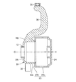
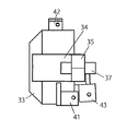
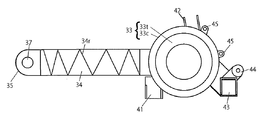
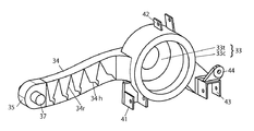
- the cylindrical portion may be formed integrally with the first arm portion on the outer peripheral surface thereof.
- the first arm portion formed integrally with the in-wheel motor drive device passes through the annular space between the outer peripheral surface of the speed reduction portion and the inner peripheral surface of the road wheel, and the outer side of the road wheel. It is possible to extend to Thereby, the layout arrangement
- positioning of a 1st arm part can be made suitable as a suspension member for steered wheels or a non-steered wheel.
- the end face portion of the speed reduction part casing is located at a position closest to the wheel in the speed reduction part, the vehicle body load supported by the first arm part can be transmitted to the wheel at a short distance in the axial direction.
- the connection location of the 1st arm formed integrally and the speed reduction part casing may extend from the outer peripheral surface of the speed reduction part casing to the other end surface in the axial direction.
- the first arm portion of the present invention can support the vehicle body load and serve as a suspension member for the suspension device.
- the distal end of the first arm portion of the present invention may be rotatably connected to the free end of the suspension arm of the suspension device.
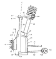
- the first arm portion protrudes upward from the speed reduction portion casing, and the upper end of the first arm portion is rotatably connected to the free end of the upper arm of the double wishbone suspension device.
- a joint portion that is integrally formed with the speed reduction portion casing and that is connected to the lower arm free end of the double wishbone suspension device may be further provided.
- the in-wheel motor drive device 11 drives a steered wheel disposed on the outer side in the vehicle width direction of the vehicle, and is provided in an inner space area of the road wheel of the steered wheel.
- the axis O of the in-wheel motor drive device 11 extends in parallel with the vehicle width direction as shown in FIGS. As a result, the vehicle travels straight.
- the in-wheel motor drive device 11 steers around a turning axis line (not shown) extending in the vertical direction together with the steered wheels.
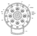
- the motion conversion mechanism takes out the rotation of the curved plate 26 and outputs only the rotation to the hub wheel 12, and includes a plurality of through holes 30a formed in the curved plate 26 at intervals in the circumferential direction,
- the inner pin 28 has an outer diameter smaller than the inner diameter of the through hole 30a and passes through each through hole 30a, and a flange portion (not shown) that commonly supports one end of each inner pin 28.
- the flange portion is coaxially attached and fixed to the hub wheel 12 of the hub portion 11C.
- the eccentric member 25 and the curved plate 26 are arranged eccentrically from the axis O.
- the upper arm 61 can swing in the vertical direction with the vehicle width direction inner ends 61b and 61c as base ends and the vehicle width direction outer ends 61a as free ends.
- a ball portion of a ball joint is provided on the outer end 61a of the upper arm 61 in the vehicle width direction.
- the outer spherical surface of the ball portion is surrounded by the inner spherical surface of the joint portion 35.
- the vehicle width direction outer side end 61a of the upper arm 61 is rotatably connected to the upper end portion of the first arm portion 34 via the ball joint.
- the lower arm 62 can swing in the vertical direction with the vehicle width direction inner ends 62b and 62c as base ends and the vehicle width direction outer ends 62a as free ends.
- a ball portion of a ball joint is provided on the outer end 62a of the lower arm 62 in the vehicle width direction.
- the outer spherical surface of the ball portion is surrounded by an inner spherical surface of a ball joint (not shown) fixed to the lower arm bracket 36.
- the vehicle width direction outer side end 62a of the lower arm 62 is rotatably connected to the lower portion of the speed reduction unit casing 33 via the ball joint.
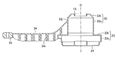
- the casing of the in-wheel motor drive device 11 will be described in detail with reference to FIG.
- the casing that constitutes the outline of the in-wheel motor drive device 11 is an assembly of three members: a reduction part casing 33 that constitutes the outline of the reduction part 11B, and a motor casing 23 and a motor cover 24 that constitute the outline of the motor part 11A. It is a thing.
- the first arm portion 34 is separated from the inward flange portion 23t of the motor portion casing 23.
- the inward flange portion 23t is connected and fixed to the end portion of the cylindrical portion 33c on the inner diameter side.
- the speed reducing portion casing end surface portion 33t is connected and fixed to the end portion of the outer ring member 13 on the inner diameter side thereof.
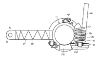
- the first arm portion 34 supports the vehicle body load and serves as a suspension member of the suspension device. That is, the tip end of the first arm portion 34 is rotatably connected to the outer end 61a in the vehicle width direction serving as the free end of the upper arm 61 of the suspension device via the ball joint (joint portion 35). Therefore, when the vehicle employs a double wishbone type suspension device, it is possible to reduce the weight of unsprung weight, increase the strength of unsprung parts, and reduce the number of unsprung parts.
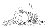
- the second bracket 42 is formed integrally with the cylindrical portion 33 c of the speed reduction unit casing 33.
- the second bracket 42 is disposed on the outer peripheral surface of the upper part on the rear side (rear side of the vehicle) of the speed reduction unit casing 33.
- the 2nd bracket 42 is connected with the vehicle width direction outer side end 64a of the 2nd link 64 via the axis
- the third bracket 43 is formed integrally with the cylindrical portion 33 c of the speed reduction unit casing 33.
- the third bracket 43 is disposed on the outer peripheral surface of the lower part of the rear side (rear side of the vehicle) of the speed reduction unit casing 33.
- the 3rd bracket 43 is connected with the vehicle width direction outer side end 65a of the 3rd link 65 via the axis
- the fourth bracket 44 is formed integrally with the cylindrical portion 33 c of the speed reduction unit casing 33 behind the third bracket 43.
- the fourth bracket 44 is disposed on the outer peripheral surface of the lower part of the rear side of the speed reduction unit casing 33.
- the 4th bracket 44 is connected with the lower end 68a of the damper 68 via the axis
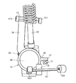
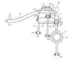
- the first link 63 to the third link 65 extend in the vehicle width direction, the outer end in the vehicle width direction is a free end, and the inner end in the vehicle width direction is a base end. It can swing in the vertical direction.
- the vehicle width direction inner ends of the first link 63 to the third link 65 are connected to a vehicle body (not shown) via a shaft so as to be rotatable.
- the outer ends in the vehicle width direction of the first link 63 to the third link 65 are rotatably connected to the first bracket 41 to the third bracket 43 via shafts.
- the first link 63 to the third link 65 allow the vertical swing while restricting the position in the vehicle width direction of the first arm portion 34 that becomes the trailing arm.
- the damper 68 extends in the vertical direction, has an upper end attached to the vehicle body side, and a lower end rotatably connected to the fourth bracket 44 via a shaft.
- the damper 68 attenuates the swing of the in-wheel motor drive device 11 in the vertical direction (see FIG. 15).
Landscapes
- Engineering & Computer Science (AREA)
- Mechanical Engineering (AREA)
- Chemical & Material Sciences (AREA)
- Combustion & Propulsion (AREA)
- Transportation (AREA)
- Vehicle Body Suspensions (AREA)
- Arrangement Or Mounting Of Propulsion Units For Vehicles (AREA)
Priority Applications (3)
| Application Number | Priority Date | Filing Date | Title |
|---|---|---|---|
| US15/021,331 US10011164B2 (en) | 2013-09-19 | 2014-09-02 | In-wheel motor drive unit |
| EP14846110.6A EP3047996B1 (en) | 2013-09-19 | 2014-09-02 | In-wheel motor driving device |
| CN201480051094.3A CN105555573B (zh) | 2013-09-19 | 2014-09-02 | 轮内电动机驱动装置 |
Applications Claiming Priority (2)
| Application Number | Priority Date | Filing Date | Title |
|---|---|---|---|
| JP2013194354A JP6271196B2 (ja) | 2013-09-19 | 2013-09-19 | インホイールモータ駆動装置 |
| JP2013-194354 | 2013-09-19 |
Publications (1)
| Publication Number | Publication Date |
|---|---|
| WO2015041038A1 true WO2015041038A1 (ja) | 2015-03-26 |
Family
ID=52688692
Family Applications (1)
| Application Number | Title | Priority Date | Filing Date |
|---|---|---|---|
| PCT/JP2014/073008 Ceased WO2015041038A1 (ja) | 2013-09-19 | 2014-09-02 | インホイールモータ駆動装置 |
Country Status (5)
| Country | Link |
|---|---|
| US (1) | US10011164B2 (enExample) |
| EP (1) | EP3047996B1 (enExample) |
| JP (1) | JP6271196B2 (enExample) |
| CN (1) | CN105555573B (enExample) |
| WO (1) | WO2015041038A1 (enExample) |
Families Citing this family (19)
| Publication number | Priority date | Publication date | Assignee | Title |
|---|---|---|---|---|
| JP6313610B2 (ja) * | 2014-02-27 | 2018-04-18 | Ntn株式会社 | インホイールモータ駆動装置とダンパとの連結構造およびこの連結構造を備えるサスペンション装置 |
| CN106470862B (zh) * | 2014-06-27 | 2018-10-30 | 日产自动车株式会社 | 轮毂电机车的簧下供电装置 |
| CN107278194B (zh) * | 2015-02-27 | 2021-02-05 | Ksm铸造集团有限公司 | 轮架 |
| JP6613056B2 (ja) * | 2015-06-04 | 2019-11-27 | Ntn株式会社 | インホイールモータ駆動装置用サスペンション構造 |
| DE102015213354A1 (de) * | 2015-07-16 | 2017-01-19 | Zf Friedrichshafen Ag | Längslenkervorrichtung einer antreibbaren Verbundlenkerachse mit einem Gehäuse |
| DE102015213355A1 (de) * | 2015-07-16 | 2017-01-19 | Zf Friedrichshafen Ag | Längslenkervorrichtung einer antreibbaren Verbundlenkerachse |
| JP6823417B2 (ja) * | 2016-09-30 | 2021-02-03 | Ntn株式会社 | インホイールモータ駆動装置 |
| US10527130B2 (en) * | 2016-09-30 | 2020-01-07 | Grant Shirley | Gear lift box assembly |
| JP6125083B1 (ja) | 2016-10-17 | 2017-05-10 | Ntn株式会社 | インホイールモータ駆動装置 |
| CN110121441B (zh) * | 2017-01-10 | 2022-06-17 | 日立安斯泰莫株式会社 | 马达驱动装置 |
| KR101887875B1 (ko) * | 2017-02-28 | 2018-08-13 | 현대위아(주) | 인 휠 모터 시스템 |
| JP2019043412A (ja) * | 2017-09-04 | 2019-03-22 | トヨタ自動車株式会社 | インホイールモータユニットとストラット式サスペンション装置との連結構造 |
| JP7103173B2 (ja) * | 2018-11-05 | 2022-07-20 | トヨタ自動車株式会社 | サスペンション装置、車両 |
| GB2582642B (en) * | 2019-03-29 | 2021-06-16 | Protean Electric Ltd | A double wishbone suspension system for an in-wheel electric motor |
| CN113910897A (zh) * | 2020-07-09 | 2022-01-11 | 浙江盘毂动力科技有限公司 | 轮边驱动装置 |
| EP4392265A4 (en) * | 2022-03-21 | 2025-10-01 | Tuzunoglu Kalip Sanayi Ve Ticaret A S | TRANSFORMATION OF MOTOR LAND VEHICLES INTO ELECTRIC VEHICLES BY CHANGING TIRES |
| TR2022004283A2 (tr) | 2022-03-21 | 2022-05-23 | Tuezuenoglu Kalip Sanayi Ve Ticaret Anonim Sirketi | Motorlu kara taşitlarinin lasti̇k deği̇şti̇rerek elektri̇kli̇ araca dönüşümü |
| JP7635750B2 (ja) * | 2022-04-06 | 2025-02-26 | トヨタ自動車株式会社 | インホイールモータの冷却構造 |
| JP7718335B2 (ja) * | 2022-06-28 | 2025-08-05 | トヨタ自動車株式会社 | インホイールモータの支持構造 |
Citations (7)
| Publication number | Priority date | Publication date | Assignee | Title |
|---|---|---|---|---|
| JP2005178410A (ja) | 2003-12-16 | 2005-07-07 | Honda Motor Co Ltd | ハイマウント型ダブルウイッシュボーン式サスペンション装置 |
| JP2005271909A (ja) * | 2004-02-26 | 2005-10-06 | Toyota Motor Corp | 配線装置 |
| JP2008189062A (ja) * | 2007-02-01 | 2008-08-21 | Toyota Motor Corp | インホイールモータ |
| JP2010116017A (ja) | 2008-11-12 | 2010-05-27 | Ntn Corp | インホイールモータ駆動装置およびインホイールモータ駆動装置用ケーシング |
| JP2011240739A (ja) * | 2010-05-14 | 2011-12-01 | Ntn Corp | インホイールモータ駆動装置 |
| WO2012123175A1 (de) * | 2011-03-16 | 2012-09-20 | Zf Friedrichshafen Ag | Antriebsvorrichtung zum antreiben eines rades für ein elektrisch antreibbares fahrzeug |
| JP2013124016A (ja) * | 2011-12-15 | 2013-06-24 | Toyota Motor Corp | 車輪駆動装置 |
Family Cites Families (8)
| Publication number | Priority date | Publication date | Assignee | Title |
|---|---|---|---|---|
| US5327034A (en) * | 1992-07-14 | 1994-07-05 | Hydro-Quebec | Electrically motorized wheel assembly |
| FR2726230A1 (fr) * | 1994-10-27 | 1996-05-03 | Peugeot | Dispositif et systeme de motopropulsion pour vehicule automobile |
| JP2003002277A (ja) * | 2001-06-27 | 2003-01-08 | Yamaha Motor Co Ltd | 電動式動力ユニット、電動車両および電動二輪車 |
| JP4225134B2 (ja) * | 2003-06-25 | 2009-02-18 | トヨタ自動車株式会社 | 車両用懸架装置 |
| CN201264516Y (zh) * | 2008-08-29 | 2009-07-01 | 沈阳华晨金杯汽车有限公司 | 一种电动汽车轮毂电机集成结构 |
| CN102666171B (zh) * | 2009-11-13 | 2015-09-09 | Ntn株式会社 | 轮毂电机驱动装置 |
| JP2011240765A (ja) * | 2010-05-17 | 2011-12-01 | Ntn Corp | インホイールモータ駆動装置 |
| JP5685112B2 (ja) * | 2011-03-07 | 2015-03-18 | Ntn株式会社 | 電気自動車用駆動装置 |
-
2013
- 2013-09-19 JP JP2013194354A patent/JP6271196B2/ja not_active Expired - Fee Related
-
2014
- 2014-09-02 US US15/021,331 patent/US10011164B2/en not_active Expired - Fee Related
- 2014-09-02 EP EP14846110.6A patent/EP3047996B1/en active Active
- 2014-09-02 WO PCT/JP2014/073008 patent/WO2015041038A1/ja not_active Ceased
- 2014-09-02 CN CN201480051094.3A patent/CN105555573B/zh not_active Expired - Fee Related
Patent Citations (7)
| Publication number | Priority date | Publication date | Assignee | Title |
|---|---|---|---|---|
| JP2005178410A (ja) | 2003-12-16 | 2005-07-07 | Honda Motor Co Ltd | ハイマウント型ダブルウイッシュボーン式サスペンション装置 |
| JP2005271909A (ja) * | 2004-02-26 | 2005-10-06 | Toyota Motor Corp | 配線装置 |
| JP2008189062A (ja) * | 2007-02-01 | 2008-08-21 | Toyota Motor Corp | インホイールモータ |
| JP2010116017A (ja) | 2008-11-12 | 2010-05-27 | Ntn Corp | インホイールモータ駆動装置およびインホイールモータ駆動装置用ケーシング |
| JP2011240739A (ja) * | 2010-05-14 | 2011-12-01 | Ntn Corp | インホイールモータ駆動装置 |
| WO2012123175A1 (de) * | 2011-03-16 | 2012-09-20 | Zf Friedrichshafen Ag | Antriebsvorrichtung zum antreiben eines rades für ein elektrisch antreibbares fahrzeug |
| JP2013124016A (ja) * | 2011-12-15 | 2013-06-24 | Toyota Motor Corp | 車輪駆動装置 |
Non-Patent Citations (1)
| Title |
|---|
| SATOSHI MURATA: "Proceedings No. 28-10", 2010, SOCIETY OF AUTOMOTIVE ENGINEERS OF JAPAN, INC., article "139-20105175 Development of In-Wheel Motor Drive Unit" |
Also Published As
| Publication number | Publication date |
|---|---|
| US20160221432A1 (en) | 2016-08-04 |
| CN105555573B (zh) | 2018-09-14 |
| CN105555573A (zh) | 2016-05-04 |
| US10011164B2 (en) | 2018-07-03 |
| EP3047996B1 (en) | 2019-10-30 |
| EP3047996A1 (en) | 2016-07-27 |
| JP6271196B2 (ja) | 2018-01-31 |
| JP2015058825A (ja) | 2015-03-30 |
| EP3047996A4 (en) | 2017-05-17 |
Similar Documents
| Publication | Publication Date | Title |
|---|---|---|
| JP6271196B2 (ja) | インホイールモータ駆動装置 | |
| JP6853622B2 (ja) | インホイールモータ駆動装置、およびインホイールモータ駆動装置とサスペンション装置の連結構造 | |
| US8186467B2 (en) | Wheel rotating device for in-wheel motor vehicle | |
| CN107848402B (zh) | 轮内电动机驱动装置与支柱式悬架装置的连结结构 | |
| CN104691304B (zh) | 轮毂总成及具备上述轮毂总成的车辆 | |
| CN107848397B (zh) | 轮内电动机驱动装置 | |
| JP6794211B2 (ja) | インホイールモータ駆動装置 | |
| CN103917434A (zh) | 车轮的转向装置 | |
| WO2018056283A1 (ja) | インホイールモータ駆動装置用サスペンション構造 | |
| JP2020104766A (ja) | インホイールモータ駆動装置を備えた車両 | |
| JP2018052423A (ja) | インホイールモータ駆動装置 | |
| JP4967789B2 (ja) | 車輪駆動装置 | |
| JP6781608B2 (ja) | インホイールモータ駆動装置 | |
| JP6786354B2 (ja) | インホイールモータ駆動装置 | |
| JP5616239B2 (ja) | 走行車両 | |
| JP2018065457A (ja) | インホイールモータ駆動装置 | |
| CN108274988B (zh) | 具有动态吸振功能的轮边电驱动系统 | |
| WO2017057067A1 (ja) | インホイールモータ駆動装置、およびインホイールモータ駆動装置とサスペンション装置の連結構造 | |
| JP2020132081A (ja) | インホイールモータ駆動装置 | |
| CN110315959A (zh) | 轮内电动机驱动装置与悬架装置的连结结构 | |
| KR20180032446A (ko) | 스프링 회전형 능동 서스펜션 | |
| WO2018083810A1 (ja) | インホイールモータ駆動装置 | |
| JP2012001017A (ja) | 車両用駆動装置 | |
| WO2017163480A1 (ja) | インホイールモータ駆動装置 |
Legal Events
| Date | Code | Title | Description |
|---|---|---|---|
| WWE | Wipo information: entry into national phase |
Ref document number: 201480051094.3 Country of ref document: CN |
|
| 121 | Ep: the epo has been informed by wipo that ep was designated in this application |
Ref document number: 14846110 Country of ref document: EP Kind code of ref document: A1 |
|
| WWE | Wipo information: entry into national phase |
Ref document number: 15021331 Country of ref document: US |
|
| REEP | Request for entry into the european phase |
Ref document number: 2014846110 Country of ref document: EP |
|
| WWE | Wipo information: entry into national phase |
Ref document number: 2014846110 Country of ref document: EP |
|
| NENP | Non-entry into the national phase |
Ref country code: DE |