WO2015041008A1 - 車両用シートリフター装置 - Google Patents
車両用シートリフター装置 Download PDFInfo
- Publication number
- WO2015041008A1 WO2015041008A1 PCT/JP2014/072249 JP2014072249W WO2015041008A1 WO 2015041008 A1 WO2015041008 A1 WO 2015041008A1 JP 2014072249 W JP2014072249 W JP 2014072249W WO 2015041008 A1 WO2015041008 A1 WO 2015041008A1
- Authority
- WO
- WIPO (PCT)
- Prior art keywords
- rotation
- locking lever
- engagement
- vehicle seat
- operation handle
- Prior art date
- Legal status (The legal status is an assumption and is not a legal conclusion. Google has not performed a legal analysis and makes no representation as to the accuracy of the status listed.)
- Ceased
Links
Images














Classifications
-
- B—PERFORMING OPERATIONS; TRANSPORTING
- B60—VEHICLES IN GENERAL
- B60N—SEATS SPECIALLY ADAPTED FOR VEHICLES; VEHICLE PASSENGER ACCOMMODATION NOT OTHERWISE PROVIDED FOR
- B60N2/00—Seats specially adapted for vehicles; Arrangement or mounting of seats in vehicles
- B60N2/02—Seats specially adapted for vehicles; Arrangement or mounting of seats in vehicles the seat or part thereof being movable, e.g. adjustable
- B60N2/04—Seats specially adapted for vehicles; Arrangement or mounting of seats in vehicles the seat or part thereof being movable, e.g. adjustable the whole seat being movable
- B60N2/16—Seats specially adapted for vehicles; Arrangement or mounting of seats in vehicles the seat or part thereof being movable, e.g. adjustable the whole seat being movable height-adjustable
- B60N2/1605—Seats specially adapted for vehicles; Arrangement or mounting of seats in vehicles the seat or part thereof being movable, e.g. adjustable the whole seat being movable height-adjustable characterised by the cinematic
- B60N2/161—Rods
- B60N2/1615—Parallelogram-like structure
-
- B—PERFORMING OPERATIONS; TRANSPORTING
- B60—VEHICLES IN GENERAL
- B60N—SEATS SPECIALLY ADAPTED FOR VEHICLES; VEHICLE PASSENGER ACCOMMODATION NOT OTHERWISE PROVIDED FOR
- B60N2/00—Seats specially adapted for vehicles; Arrangement or mounting of seats in vehicles
- B60N2/02—Seats specially adapted for vehicles; Arrangement or mounting of seats in vehicles the seat or part thereof being movable, e.g. adjustable
- B60N2/0224—Non-manual adjustments, e.g. with electrical operation
- B60N2/02246—Electric motors therefor
-
- B—PERFORMING OPERATIONS; TRANSPORTING
- B60—VEHICLES IN GENERAL
- B60N—SEATS SPECIALLY ADAPTED FOR VEHICLES; VEHICLE PASSENGER ACCOMMODATION NOT OTHERWISE PROVIDED FOR
- B60N2/00—Seats specially adapted for vehicles; Arrangement or mounting of seats in vehicles
- B60N2/02—Seats specially adapted for vehicles; Arrangement or mounting of seats in vehicles the seat or part thereof being movable, e.g. adjustable
- B60N2/04—Seats specially adapted for vehicles; Arrangement or mounting of seats in vehicles the seat or part thereof being movable, e.g. adjustable the whole seat being movable
- B60N2/06—Seats specially adapted for vehicles; Arrangement or mounting of seats in vehicles the seat or part thereof being movable, e.g. adjustable the whole seat being movable slidable
-
- B—PERFORMING OPERATIONS; TRANSPORTING
- B60—VEHICLES IN GENERAL
- B60N—SEATS SPECIALLY ADAPTED FOR VEHICLES; VEHICLE PASSENGER ACCOMMODATION NOT OTHERWISE PROVIDED FOR
- B60N2/00—Seats specially adapted for vehicles; Arrangement or mounting of seats in vehicles
- B60N2/02—Seats specially adapted for vehicles; Arrangement or mounting of seats in vehicles the seat or part thereof being movable, e.g. adjustable
- B60N2/04—Seats specially adapted for vehicles; Arrangement or mounting of seats in vehicles the seat or part thereof being movable, e.g. adjustable the whole seat being movable
- B60N2/16—Seats specially adapted for vehicles; Arrangement or mounting of seats in vehicles the seat or part thereof being movable, e.g. adjustable the whole seat being movable height-adjustable
- B60N2/1635—Seats specially adapted for vehicles; Arrangement or mounting of seats in vehicles the seat or part thereof being movable, e.g. adjustable the whole seat being movable height-adjustable characterised by the drive mechanism
- B60N2/165—Gear wheel driven mechanism
-
- B—PERFORMING OPERATIONS; TRANSPORTING
- B60—VEHICLES IN GENERAL
- B60N—SEATS SPECIALLY ADAPTED FOR VEHICLES; VEHICLE PASSENGER ACCOMMODATION NOT OTHERWISE PROVIDED FOR
- B60N2/00—Seats specially adapted for vehicles; Arrangement or mounting of seats in vehicles
- B60N2/02—Seats specially adapted for vehicles; Arrangement or mounting of seats in vehicles the seat or part thereof being movable, e.g. adjustable
- B60N2/04—Seats specially adapted for vehicles; Arrangement or mounting of seats in vehicles the seat or part thereof being movable, e.g. adjustable the whole seat being movable
- B60N2/16—Seats specially adapted for vehicles; Arrangement or mounting of seats in vehicles the seat or part thereof being movable, e.g. adjustable the whole seat being movable height-adjustable
- B60N2/1635—Seats specially adapted for vehicles; Arrangement or mounting of seats in vehicles the seat or part thereof being movable, e.g. adjustable the whole seat being movable height-adjustable characterised by the drive mechanism
- B60N2/167—Ratchet mechanism
-
- B—PERFORMING OPERATIONS; TRANSPORTING
- B60—VEHICLES IN GENERAL
- B60N—SEATS SPECIALLY ADAPTED FOR VEHICLES; VEHICLE PASSENGER ACCOMMODATION NOT OTHERWISE PROVIDED FOR
- B60N2/00—Seats specially adapted for vehicles; Arrangement or mounting of seats in vehicles
- B60N2/02—Seats specially adapted for vehicles; Arrangement or mounting of seats in vehicles the seat or part thereof being movable, e.g. adjustable
- B60N2/04—Seats specially adapted for vehicles; Arrangement or mounting of seats in vehicles the seat or part thereof being movable, e.g. adjustable the whole seat being movable
- B60N2/16—Seats specially adapted for vehicles; Arrangement or mounting of seats in vehicles the seat or part thereof being movable, e.g. adjustable the whole seat being movable height-adjustable
- B60N2/169—Stepwise movement mechanisms, e.g. ratchets
Definitions
- the present invention relates to a vehicle seat lifter device.
- a seat lifter device that can adjust the position of a vehicle seat in the vertical direction includes a link mechanism that supports the seat upward via a link member that is rotatably provided.
- a link member that is rotatably provided.
- any one of the link members is provided with a sector gear having a common rotation shaft and rotating integrally with the link member. The link member rotates based on the driving force transmitted through the sector gear, so that the seat supported above the link mechanism can be moved up and down.
- the seat lifter device described in Patent Document 1 includes a pinion gear meshed with a sector gear, and an operation handle provided coaxially with the pinion gear.
- a rotation control device having two clutch portions arranged coaxially is provided between the pinion gear and the operation handle. The rotation control device can rotationally drive the pinion gear based on the reciprocating rotation operation input to the operation handle and hold the rotation position.
- the present invention has been made to solve the above-described problems, and an object of the present invention is to provide a vehicle seat lifter device including a rotation control device that can be reduced in size with a simple configuration. .
- a vehicle seat lifter includes a link mechanism that supports a seat upward via a link member that is rotatably provided, and the link member and the rotation shaft are shared to rotate integrally.
- a rotation control device, and the rotation control device is provided with a pinion gear and a rotation shaft sharing a rotation shaft, and rotates integrally with the pinion gear at a position coaxial with the pinion gear.
- An engaging member a locking lever capable of restricting rotation of the pinion gear by engaging with the claw wheel, and a state of engaging with the claw wheel based on a rotation operation of the operating handle in the first direction.
- a drive lever that rotates the pinion gear in a direction in which the seat moves upward by rotating together with the operation member, and the locking lever rotates the pinion gear when the seat moves upward
- the rotation control device further detaches the locking lever and the drive lever from the claw wheel based on a rotation operation of the operation handle in the second direction.
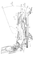
- the perspective view of a vehicle seat The side view of the seat lifter apparatus provided in the vehicle seat.
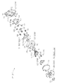
- the side view of a vehicle seat The perspective view of the operation handle and rotation control device which constitute a seat lifter device.
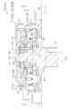
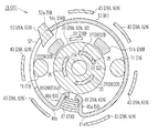
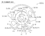
- the side view of a rotation control apparatus Sectional drawing of the rotation control apparatus in 1st Embodiment (VII-VII cross section in FIG. 6). Sectional drawing of the rotation control apparatus in 1st Embodiment (VIII-VIII cross section in FIG. 6).
- Sectional drawing of a rotation control apparatus (XI-XI cross section in FIG. 7).
- (A) and (b) are the operation explanatory views of a connection mechanism. Operation
- Operation movement explanatory drawing of the handle returning apparatus in 1st Embodiment (at the time of 2nd direction rotation operation: Maximum).
- Action operation explanatory drawing of the handle return apparatus in 1st Embodiment.
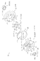
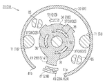
- Sectional drawing of a rotation control apparatus (XIX-XIX cross section in FIG. 7).
- movement explanatory drawing of a rotation control apparatus at the time of 1st direction rotation operation: The middle).
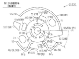
- movement explanatory drawing of a rotation control apparatus at the time of a 1st direction rotation operation: Maximum).
- Operation movement explanatory drawing of a rotation control apparatus (at the time of 2nd direction rotation operation: The middle). Operation
- (A) is an operation explanatory view of a holding engagement part provided in a drive lever. The perspective view of the spring member in 2nd Embodiment. The perspective view of the 2nd input member in a 2nd embodiment. Operation
- the vehicle seat 1 includes a seat cushion 2 and a seat back 3 provided so as to be tiltable with respect to a rear end portion of the seat cushion 2.
- a pair of left and right lower rails 5 supported on the bracket 4 are provided on the floor of a vehicle (not shown). Further, an upper rail 6 that moves relative to each lower rail 5 is mounted on these lower rails 5. The seat 1 is supported on the upper rails 6.
- the seat slide device 7 is formed by the lower rail 5 and the upper rail 6 that are provided so as to be relatively movable. The vehicle occupant can adjust the position of the seat 1 in the vehicle front-rear direction (left-right direction in FIG. 2) by using the function of the seat slide device 7.
- the seat 1 of the present embodiment is fixed to each upper rail 6 via a seat lifter device 10.
- the vehicle occupant can adjust the position of the seat 1 in the vertical direction (height adjustment of the seat cushion 2) by using the function of the seat lifter device 10.
- the seat lifter device 10 includes a link mechanism 12 that supports the seat 1 upward via two link members 11 that are rotatably provided.
- One of the two link members 11 is rotatably connected to the front end portion 13a of the side frame 13 constituting the skeleton of the seat cushion 2 and the front end portion 8a of the support member 8 provided on the upper rail 6. It is provided as a forward link 14.
- the other link member 11 is provided as a rear link 15 that is rotatably connected to the rear end portion 13 b of the side frame 13 and the rear end portion 8 b of the support member 8. That is, a known parallel link mechanism is used for the link mechanism 12 of the present embodiment. And based on rotation of each link member 11, it is possible to raise / lower the sheet
- connection points X1 and X2 of the front link 14 and the rear link 15 with respect to the side frame 13 are the connection points X3 of the front link 14 and the rear link 15 with respect to the support member 8.
- X4 are arranged on the vehicle rear side.
- the seat 1 supported above the link mechanism 12 rotates the link members 11 so that the connection points X1 and X2 between the side frames 13 and the link members 11 move to the vehicle front side. , Move up. And each link member 11 rotates so that each connection point X1, X2 may move to the vehicle rear side, and it moves below.
- the rear link 15 that is one of the two link members 11 constituting the link mechanism 12 and is connected to the right side frame 13 is rotated at the connection point X2.
- a sector gear 16 is formed as a moving center. That is, the sector gear 16 rotates integrally with the rear link 15 and the rotation axis Q1.
- the torque rod 17 connecting the left and right side frames 13 (rear end portions 13b) constitutes the rotation axis Q1 of the rear link 15.
- the link mechanism 12 of this embodiment can raise / lower the sheet
- an operation handle 20 that is rotated to move the seat 1 up and down.
- a pinion gear 18 is meshed with the sector gear 16.
- a rotation control device 21 is interposed between the pinion gear 18 and the operation handle 20.
- the operation torque input to the operation handle 20 is transmitted to the pinion gear 18 via the rotation control device 21.
- an operation torque associated with a lifting operation of the operation handle 20 described later is transmitted to the pinion gear 18.
- the rotation control device 21 controls the rotation of the pinion gear 18 so that the vertical position of the seat 1 supported above the link mechanism 12 can be adjusted.
- the rotation control device 21 includes a rotating shaft 22 provided with the pinion gear 18 at one end thereof, and a bracket 23 that rotatably supports the rotating shaft 22. ing.
- the bracket 23 of the present embodiment is opposed to the side frame 13 constituting the skeleton of the seat cushion 2 as described above, specifically, the first bracket 23A fixed to the outer side surface 13c, and the first bracket 23A. And a second bracket 23B provided.
- the first bracket 23A and the second bracket 23B are formed by plastic processing (pressing) a metal plate material.
- the first bracket 23A and the second bracket 23B are formed with through holes 25a and 25b that face each other. And the said rotating shaft 22 is rotatably supported in the state penetrated by these through-holes 25a and 25b.
- the side frame 13 of the present embodiment is formed with a through hole 26 into which the first end 22a of the rotary shaft 22 provided with the pinion gear 18 can be inserted.
- the pinion gear 18 can be engaged with the sector gear 16 provided adjacent to the inner side surface 13d of the side frame 13 through the through hole 26 ( (See FIG. 2).
- the rotation control device 21 of the present embodiment includes an input member 28 that rotates in conjunction with the operation handle 20, a spring member 30 that is configured to be elastically deformed based on a rotation operation on the operation handle 20, It has.
- the input member 28 is biased based on the return force (elastic force) generated by the spring member 30 to return the rotated operation handle 20 to the neutral position P0.
- a possible handle return device 31 is provided in the rotation control device 21.
- the operation handle 20 of the present embodiment has a lever shape in which a handle portion 20a provided at the tip of the operation handle 20 extends toward the front side of the vehicle.
- a position where the handle portion 20a is substantially horizontal with respect to the floor portion of the vehicle is set as a neutral position P0.
- the proximal end of the handle portion 20 a is connected to the rotation control device 21.
- the operation handle 20 is rotated in a direction in which the handle portion 20a provided at the tip is pulled up (first direction) or in a direction in which it is pushed down (second direction).
- first direction a direction in which the handle portion 20a provided at the tip is pulled up
- second direction a direction in which it is pushed down
- the handle return device 31 of the present embodiment includes first and second input members 28A and 28B that are coaxially arranged so as to be relatively rotatable. Further, the handle returning device 31 of the present embodiment includes a connecting mechanism 32 that connects the first input member 28A and the second input member 28B so that torque can be transmitted. In the present embodiment, the operation handle 20 is fixed to the first input member 28A.
- the first and second input members 28A and 28B are formed by plastic working (pressing) a metal plate material.
- the first and second input members 28A and 28B are provided with disc portions 33 and 34 having circular holes 33a and 34a, respectively, at the center thereof.
- Each of the disk parts 33 and 34 is an example of a circular part.
- the second end 22b of the rotary shaft 22 is inserted into the circular holes 33a and 34a, whereby the first and second input members 28a and 28b are rotated relative to the rotary shaft 22 as the support shaft Q2. It is pivotally supported.
- the disk portions 33 and 34 of the first and second input members 28A and 28B have a plurality (three in the present embodiment) extending in the circumferential direction on the radially outer side of the circular holes 33a and 34a, respectively.
- Engaging holes 35 and 36 are formed.
- each engagement hole 35, 36 has a substantially arc-shaped long hole shape
- the engagement holes 35 are formed at equal intervals around the circular hole 33a
- the engagement holes 36 are circular holes 34a.
- the handle returning device 31 according to this embodiment has a plurality of (three in this embodiment) engagements that engage with both the engagement holes 35 and 36 of the first input member 28A and the second input member 28B.
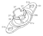
- a connecting member 38 having a mating protrusion 37 is provided.
- the connecting member 38 has a substantially cylindrical outer shape.
- Each engagement protrusion 37 surrounds one end (second end 38 b) arranged adjacent to the second end 22 b (upper side in FIGS. 7 and 8) of the rotating shaft 22. It is formed by cutting out at equal intervals along the direction.
- Each engagement protrusion 37 has an arc-shaped cross section extending in the circumferential direction, like the respective engagement holes 35 and 36 of the first input member 28A and the second input member 28B.
- the connecting member 38 is arranged coaxially with the rotary shaft 22 by inserting the rotary shaft 22 into the cylinder. That is, the connecting member 38 is inserted through the through hole 25b formed in the second bracket 23B.
- each engagement protrusion part 37 is the aspect which penetrates 1st input member 28A with 2nd input member 28B (lower side in FIG.7 and FIG.8) located in the side near 2nd bracket 23B, The first and second input members 28A and 28B are inserted into both the engagement holes 35 and 36.
- the handle return device 31 of the present embodiment includes a substantially disc-shaped attachment member 39.
- a plurality of attachment members 39 (fitting to the distal ends of the engagement protrusions 37 inserted through both the engagement holes 35 and 36 and the insertion hole 39a through which the second end 22b of the rotary shaft 22 is inserted.
- the sliding plate 40 (see FIG. 5) attached to the through hole 25b of the second bracket 23B and the mounting member 39 By sandwiching the disk portions 33 and 34 of the first and second input members 28A and 28B in between, the axial movement of the first and second input members 28A and 28B is restricted. Yes.
- each engagement hole 36 formed in the disc portion 34 of the second input member 28 ⁇ / b> B is set substantially equal to the circumferential length of each engagement protrusion 37.
- the relative circumferential movement of each engagement protrusion 37 in each engagement hole 36 is restricted, so that the second input member 28B and the connection member 38 are connected so as not to be relatively rotatable. It has become.
- each engagement hole 35 formed in the disk portion 33 of the first input member 28 ⁇ / b> A is set longer than the circumferential length of each engagement protrusion 37. ing. That is, the engagement protrusions 37 can relatively move in the engagement holes 35 in the circumferential direction.
- the first input member 28A and the second input member 28B are coupled so as to be able to transmit torque, and the other is delayed in phase with respect to one of the first and second input members 28A, 28B.
- a connecting mechanism 32 that can be rotated is formed.
- the engagement protrusions 37 inserted into the engagement holes 35 and 36 of the first and second input members 28A and 28B are used as the first and second input members.
- the rotational torque input to one of the first and second input members 28A and 28B via the connecting member 38 is applied to the other. It is possible to communicate to.
- each engagement hole 35 and each engagement of the first input member 28A are based on the difference in circumferential length.
- a slight gap in the circumferential direction is formed between the mating protrusion 37.
- the engagement protrusions 37 are inserted into the engagement holes 35 so as to close the circumferential clearance.
- each engagement protrusion 37 that has moved through each engagement hole 35 is then engaged with one of the circumferential end portions 35a and 35b, so that torque can be transmitted via the connecting member 38.
- the first and second input members 28A and 28B are rotated at a phase delayed from the other one of the first and second input members 28A and 28B.
- the first input member 28A is used when the operation handle 20 is rotated in the first direction. In the same figure, it rotates counterclockwise.
- the coupling member 38 engages the first circumferential direction end 35a of each engagement hole 35 with each engagement protrusion 37, whereby the rotational torque in the first direction is applied to the second input member 28B. It becomes a state that can be transmitted.
- the coupling mechanism 32 according to the present embodiment is configured so that each engagement protrusion 37 moves in each engagement hole 35 until each engagement protrusion 37 is engaged with the first circumferential end 35a.
- the second input member 28B can be rotated in the first direction with a delayed phase corresponding to minutes.
- connection mechanism 32 of the present embodiment is configured so that the angle at which each engagement protrusion 37 moves in each engagement hole 35 until each engagement protrusion 37 engages with the second circumferential end 35b.
- the second input member 28B can be rotated in the second direction with a delayed phase corresponding to minutes.
- the handle return device 31 of the present embodiment is a spring extending around the rotation shaft 22 constituting the support shaft Q2 of the first and second input members 28A, 28B.
- a spring member 30 having a main body 41 is provided.
- the spring member 30 is formed as a so-called ring spring having a spring body 41 curved in a substantially arc shape (substantially C shape).
- the spring member 30 is disposed between the first input member 28A and the second bracket 23B in the axial direction of the rotary shaft 22.
- the first input member 28 ⁇ / b> A includes an annular portion 42 extending radially outward of the disc portion 33, and the rotating shaft 22 from the outer peripheral edge of the annular portion 42. And a plurality of bent portions 43 extending toward the second bracket 23B (lower side in FIGS. 7 and 8) in the axial direction. Further, in the first input member 28 ⁇ / b> A of the present embodiment, the disk portion 33 and the annular portion 42 are formed in a stepped manner so that the bent portions 43 are arranged on the radially outer side of the disk portion 33. Has been.
- the second input member 28 ⁇ / b> B of the present embodiment is formed to have a smaller diameter than the first input member 28 ⁇ / b> A so that the radially outer side thereof is surrounded by the bent portions 43.
- the spring member 30 of this embodiment is arrange
- the spring member 30 of the present embodiment includes a plurality of engaging portions (56, 58) provided at positions separated from each other in the circumferential direction of the spring main body 41 having a substantially C-shaped outer shape.
- the second bracket 23B and the first and second input members 28A, 28B are respectively connected to the spring members 30 based on the turning operation of the operation handle 20. Engagement protrusions (47 to 49, 53) that can be engaged with the joint portions (56, 58) are formed.
- the spring member 30 of the present embodiment includes bent portions 46 a and 46 b that are bent radially inward from both end portions 41 a and 41 b of the spring body 41.
- Each of the bent portions 46 a and 46 b is provided as a terminal engaging portion 56.
- the second bracket 23B and the first and second input members 28A and 28B are respectively disposed between the bent portions 46a and 46b so that they can be engaged with the spring member 30. 47 to 49 are provided.
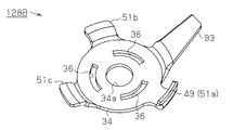
- the engaging protrusion 47 of the second bracket 23 ⁇ / b> B is a part of the substantially disc-shaped bracket body 50 that faces the annular portion 42 of the first input member 28 ⁇ / b> A. It is formed by bending toward the input member 28A. Further, the engaging protrusion 48 of the first input member 28A is formed by bending a part of the annular portion 42 toward the second bracket 23B. Further, the second input member 28B has a plurality of extending portions 51a to 51c extending radially outward from the disc portion 34. The engaging protrusion 49 of the second input member 28B is formed by bending the tip of the first extending portion 51a toward the first input member 28A.
- the engagement protrusion 47 of the second bracket 23B is disposed on the outermost radial direction.
- the engagement protrusion 49 of the second input member 28B is arranged on the innermost side in the radial direction across the engagement protrusion 48 of the first input member 28A.
- the spring body 41 of the spring member 30 is formed with a hole 52 that penetrates the spring body 41 in the radial direction.
- the hole 52 has a long hole shape extending in the circumferential direction.
- the first input member 28 ⁇ / b> A is provided with an engaging protrusion 53 that is inserted into the hole 52.
- the circumferential end 52 a of the hole 52 is provided as an intermediate engagement portion 58 formed between both ends 41 a and 41 b of the spring body 41, so that the hole 52 is inserted into the hole 52.
- the engaging protrusion 53 is adapted to engage with the spring member 30.
- the spring body 41 includes a plurality (two in this embodiment) of spring portions 55 a and 55 b.
- Each of the spring portions 55a and 55b includes a first spring and a second spring that are provided in a plurality of engaging portions 56 and 58 (46a, 46b, and 52a) formed in the spring body 41 and spaced apart in the circumferential direction.
- engaging portions 56 and 58 46a, 46b, and 52a
- end portions SP1 and SP2 As end portions SP1 and SP2.
- the bent portions 46a and 46b are set as the first and second spring end portions SP1 and SP2 of the first spring portion 55a.
- the bent portion 46a and the circumferential end portion 52a are set as the first and second spring end portions SP1 and SP2 of the second spring portion 55b.
- each spring part 55a, 55b has a different effective spring length L (length between both spring end parts SP1, SP2).
- the handle return device 31 of the present embodiment uses the first and second springs to provide a return force for returning the operation handle 20 to the neutral position P0 according to the direction of the rotation operation input to the operation handle 20. It can be generated by any one of the parts 55a and 55b.
- the first input member 28A rotates counterclockwise in each figure.
- the engagement protrusion 47 of the second bracket 23B and the engagement protrusion 48 of the first input member 28A are spaced apart in the circumferential direction.
- the engagement protrusion 47 of the second bracket 23B and the engagement protrusion 48 of the first input member 28A serve as terminal engagement portions 56 provided at both end portions 41a and 41b of the spring body 41, respectively. It engages with each bent part 46a, 46b.
- the engaging protrusion 48 of the first input member 28 ⁇ / b> A that rotates in conjunction with the operation handle 20 is arranged in the counterclockwise direction, that is, the first direction side with respect to the engaging protrusion 48. It engages with the bent portion 46a of the first end portion 41a.
- the engagement protrusion 47 of the second bracket 23B causes the spring member to rotate in the first direction. 30 is engaged with the bent portion 46b of the second end portion 41b. As a result, the spring member 30 expands so that the space between the bent portions 46a and 46b constituting the terminal engaging portion 56 is pushed and expanded.
- the handle return device 31 of the present embodiment can return the operation handle 20 operated in the first direction to the neutral position P0 based on the return force generated by the elastically deformed first spring portion 55a. It is possible.
- the engagement protrusion 53 provided on the first input member 28A is the hole 52 provided on the spring body 41, more specifically, the hole 52 located on the second direction side. Is engaged with the spring member 30 having the circumferential end portion 52 a as the intermediate engagement portion 58. As a result, the spring member 30 tries to rotate in the second direction together with the first input member 28A, so that the engaging protrusion 47 of the second bracket 23B moves to the second direction. Engage with the bent portion 46a of the first end 41a.
- the handle return device 31 of this embodiment can return the operation handle 20 operated in the second direction to the neutral position P0 based on the return force generated by the elastically deformed second spring portion 55b. It is possible.
- the spring member 30 of the present embodiment has the both end portions 41a and 41b of the spring body 41 provided with both bent portions 46a and 46b as the terminal engaging portions 56 even when the operation handle 20 is not operated.
- the first spring portions 55a having the first and second spring end portions SP1 and SP2 are configured to generate a return force.
- the handle returning device 31 of the present embodiment determines the relative rotational position between the second bracket 23B and the first and second input members 28A and 28B when the operation handle 20 is in the neutral position P0. It has a defined configuration.
- the handle return device 31 of the present embodiment is engaged during a rotation operation in the first direction in each engagement hole 35 constituting the connection mechanism 32 when the operation handle 20 is in the neutral position P0.
- the relative rotation position between the first and second input members 28A and 28B is defined so that the engaging protrusions 37 are separated from the first circumferential end 35a. .
- the second input member 28B rotates more reliably at a phase delayed from the first input member 28A to which the operation handle 20 is fixed ( (Refer FIG. 12 (a) (b)).
- the maximum operation amount ⁇ 1 (pull-up position P1) of the operation handle 20 that is generated during the rotation operation in the first direction and the rotation operation in the second direction are generated.
- the maximum operation amount ⁇ 2 of the operation handle 20 to be performed (the pushed-down position P2) is compared, the maximum operation amount ⁇ 2 during the rotation operation in the second direction is smaller.
- the first and second spring portions 55a and 55b in which different spring forces are set depending on the difference between the effective spring lengths L1 and L2 are integrally formed in the spring member 30 of the present embodiment as described above. Is formed.
- the first spring portion 55a generates a return force during a rotation operation in the first direction
- the second spring portion 55b generates a return force during a rotation operation in the second direction.
- the first spring portion 55a and the second spring portion 55b are compared, the first spring portion having the two end engaging portions 56 as both spring end portions SP1 and SP2.
- the second spring portion 55b has a larger spring force (spring constant) than the first spring portion 55a. That is, when the first spring portion 55a is a basic spring portion, the second spring portion 55b is a reinforcing spring portion capable of generating a larger return force according to the amount of elastic deformation in the circumferential direction. It has become.
- the handle returning device 31 of the present embodiment uses the difference in spring force between the first spring portion 55a and the second spring portion 55b, so that the first direction and the second direction.
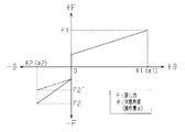
- the return force F (F1, F2) for returning the operation handle 20 to the neutral position P0 is configured to be substantially equal (F1 ⁇ F2).
- the rotation angles ⁇ 1 and ⁇ 2 are the first directions when the rotation angle of the first input member 28A that rotates based on the rotation operation of the operation handle 20 is “ ⁇ ”.
- the maximum value of the rotation angle ⁇ generated during the rotation operation in the second direction (see FIGS. 15 and 17).
- “F2 ′” indicates a configuration in which the operation handle 20 is returned to the neutral position P0 based on the return force F generated by the first spring portion 55a even in the rotation operation in the second direction. This is the maximum value of (conventional configuration).
- the second bracket 23B has a radially outer side of the second input member 28B, more specifically, the diameter of the disc portion 34.
- a stopper portion 59 that is located on the outer side in the direction and protrudes toward the first input member 28A is provided.
- the stopper portion 59 is formed by notching a part of the bracket body 50 and bending the notch portion toward the first input member 28A.
- the second bracket 23B is brought into contact with the stopper portion 59 by any one of the second extending portion 51b and the third extending portion 51c projecting radially outward from the disc portion 34. Is restricted.
- the stopper unit 59 defines the maximum operation amount ⁇ 1 of the operation handle 20 generated during the rotation operation in the first direction and the maximum operation amount ⁇ 2 of the operation handle 20 generated during the rotation operation in the second direction. (See FIG. 3).
- the rotation control device 21 of the present embodiment includes a pinion wheel 60 that rotates integrally with the pinion gear 18 and the rotation shaft 22.
- the ratchet wheel 60 has a well-known configuration in which a plurality of engagement claws are formed on the outer periphery, and is integrally formed with the rotary shaft 22.
- the pinion gear 18 is also formed integrally with the rotary shaft 22.
- the ratchet wheel 60 is disposed between the first bracket 23A and the second bracket 23B in the axial direction of the rotary shaft 22.
- the rotary shaft 22 as the support shaft Q2 rotates.
- An operation plate 61 that is supported is provided.
- the operation plate 61 is formed by plastic processing (pressing) a metal plate material.
- the operation plate 61 is formed with a through hole 61a that penetrates the operation plate 61 in the thickness direction. The operation plate 61 is pivotally supported by the rotation shaft 22 being inserted into the through hole 61a.
- the operation plate 61 transmits torque between the first input member 28A and the second input member 28B as described above.
- the first end portion 38a of the connecting member 38 constituting the connecting mechanism 32 that can be connected is connected.
- the operation plate 61 of the present embodiment is connected to the connection member 38 so as not to rotate relative to the connection member 38 by fitting the first end 38a of the connection member 38 having a substantially cylindrical shape in the through hole 61a. Yes.
- the operation plate 61 rotates at a phase delayed from the first input member 28 ⁇ / b> A that rotates in conjunction with the operation handle 20.
- the first input member 28A fixed to the operation handle 20 constitutes the first operation member 62A
- the operation plate 61 fixed to the second input member 28B is the first input member.
- a second operating member 62B that rotates at a phase delayed from the member 28A is configured.
- the rotation control device 21 according to the present embodiment is based on a relative position change between the operation member 62 (62A, 62B) and the bracket 23 (23A, 23B) generated by the rotation operation of the operation handle 20.
- the rotation of the pinion gear 18 whose rotation shaft 22 is supported by the bracket 23 is controlled.
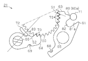
- the rotation control device 21 of the present embodiment has a plurality of (two in this embodiment) support shafts extending substantially parallel to the rotation shaft 22 by supporting both ends thereof by the first bracket 23A and the second bracket 23B. 65. Further, in the present embodiment, the two support shafts 65 are provided at positions that are equally spaced around the ratchet wheel 60 (positions that are 180 ° apart in the circumferential direction). The locking levers 63 are pivotally supported on the support shafts 65 so as to be rotatable on the radially outer side of the ratchet wheel 60.
- the rotation control device 21 of the present embodiment has one end fixed to the operation plate 61 that constitutes the second operation member 62B, so that it is substantially parallel to the rotation shaft 22 toward the first bracket 23A.
- a plurality of (two in this embodiment) support shafts 66 are provided. In the present embodiment, these support shafts 66 are also provided at positions that are equally spaced around the ratchet wheel 60 (positions that are 180 degrees apart in the circumferential direction).
- each of the support shafts 66 is fixed to the operation plate 61 by fitting one end of the support shaft into a fitting hole 61b (see FIG. 20) formed in the operation plate 61. ing.
- these support shafts 66 are connected to the support shafts 65 provided on the bracket 23 (23A, 23B) when the operation handle 20 is returned to the neutral position P0 as shown in FIG.
- the drive levers 64 are pivotally supported on the support shafts 66 so as to be rotatable on the radially outer side of the ratchet wheel 60.
- each locking lever 63 and each driving lever 64 has an engaging claw 70 provided at the tip thereof based on the elastic force of each of the torsion coil springs 68 and 69. Is rotated and biased in a direction (counterclockwise direction in FIG. 19).
- the support shaft 65 of the locking lever 63 is a substantially normal line that intersects the engaging surface S1 of the engaging claw 70 of the locking lever 63 and the claw wheel 60 (the engaging claw thereof).
- it is arranged on the side that restricts the rotation of the ratchet wheel 60 in the clockwise direction in FIG.
- a pressure angle is set that can regulate the rotation of the ratchet wheel 60 in the clockwise direction, that is, the rotation of the pinion gear 18 in the direction in which the seat 1 moves downward.
- the support shaft 66 of the drive lever 64 also has a claw wheel in the clockwise direction in FIG. 21 in a substantially normal direction intersecting the engagement surface S2 between the engagement claw 70 and the claw wheel 60 of the drive lever. It is arranged on the side that restricts the rotation of 60. Further, in FIG. 21, a pressure angle capable of rotationally driving the ratchet wheel 60 in the counterclockwise direction is set.
- the first and second operation members 62A and 62B are based on the rotation operation in the first direction for pulling up the operation handle 20 (see FIG. 3). It rotates counterclockwise.
- the drive lever 64 of the present embodiment rotates together with the operation plate 61 constituting the second operation member 62B, thereby moving along the outer periphery of the ratchet wheel 60 together with the support shaft 66 in FIG. , Move circumferentially counterclockwise.
- the drive lever 64 of the present embodiment can rotationally drive the hooked wheel 60 in the engaged state in the counterclockwise direction, that is, the direction in which the seat 1 moves upward in FIG.
- each locking lever 63 has the engaging claw 70 of the locking lever 63 when the ratchet wheel 60 rotates in the direction opposite to the regulation direction, that is, in the direction in which the seat 1 moves upward. Is configured to slide on the engagement surface S1 with the claw wheel 60 (the engagement claw thereof).
- each drive lever 64 also engages with the engagement claw of the drive lever 64 when the drive lever 64 moves in the circumferential direction in the opposite direction (clockwise direction in FIG. 19) to the direction in which the drive lever 64 rotates.
- 70 is configured to slide on the engagement surface S2 with the claw wheel 60 (the engagement claw thereof).
- the ratchet mechanism is comprised between the ratchet wheel 60 and each latching lever 63, and between the ratchet wheel 60 and each drive lever 64.
- the rotation control device 21 of the present embodiment is based on the rotation operation in the second direction that pulls down the operation handle 20 (see FIG. 3).
- a locking lever control piece 71 for releasing the engagement of each locking lever 63 and a driving lever control piece 72 for releasing the engagement of each driving lever 64 with respect to the ratchet wheel 60 are provided.
- each locking lever control piece 71 includes a shaft-like member 74 that is fixed to the first input member 28A constituting the first operation member 62A.
- a tip 74 a of the shaft-like member 74 protrudes toward the first bracket 23 ⁇ / b> A (lower side in FIG. 8) in the axial direction of the rotary shaft 22.
- a plurality of elongated holes 75 extending in the circumferential direction are formed in the bracket body 50 of the second bracket 23B. Then, each locking lever control piece 71 is inserted into each long hole 75, so that it can rotate integrally with the first operating member 62A without interfering with the second bracket 23B. Yes.
- a plurality of long holes 76 extending in the circumferential direction are formed on the first bracket 23A as well as the long holes 75 provided in the bracket body 50.
- Each locking lever control piece 71 has its tip (tip 74a of each shaft-like member 74) inserted into each slot 76.
- each locking lever control piece 71 is guided by each of the long holes 76, and based on the relative rotation of the first operation member 62A with respect to both brackets 23A, 23B, the radial direction of the ratchet wheel 60 is achieved. Move outside in the circumferential direction.
- each drive lever control piece 72 is provided on the first bracket 23A.
- each drive lever control piece 72 is formed by notching a part of the first bracket 23A and bending the notch toward the second bracket 23B. Therefore, the tip of each drive lever control piece 72 protrudes toward the second bracket 23B (upper side in FIG. 8).
- each drive lever control piece 72 is disposed at a position between the claw wheel 60 and the support shaft 66 of each drive lever 64 on the radially outer side of the claw wheel 60. As a result, the drive levers 64 move radially outward from the drive lever control pieces 72 based on the relative rotation of the second operating member 62B with respect to the brackets 23A and 23B. .
- the locking lever control piece 71 of the present embodiment is configured to come into contact with a locking lever 63 that engages the ratchet wheel 60 when the operation handle 20 is in the neutral position P0. ing.
- the locking lever control piece 71 regulates the operation of the locking lever 63 that is detached from the ratchet wheel 60, that is, the rotation of the locking lever 63 in the clockwise direction in FIG.
- the rotation of the pinion gear 18 in the upward moving direction is restricted.
- the locking lever 63 of the present embodiment includes a regulation protrusion 80 that protrudes radially outward of the ratchet wheel 60 in the engaged state with the ratchet wheel 60.
- the locking lever control piece 71 comes into contact with the tip 80a of the restricting protrusion 80.
- the locking lever control piece 71 rotates integrally with the first operation member 62 ⁇ / b> A during the rotation operation in the first direction for pulling up the operation handle 20.
- the radially outer side is moved circumferentially in the counterclockwise direction in FIG.
- the rotation of each locking lever 63 is allowed. That is, when the pinion gear 18 rotates in the direction in which the seat 1 moves upward in accordance with the rotation operation of the operation handle 20 in the first direction, the rotation operation of each locking lever 63 detached from the ratchet wheel 60 is allowed. It is like that.
- the first operation member 62A rotates in advance of the second operation member 62B.
- the second operating member 62B provided with the support shaft 66 of the drive lever 64 has the engaging projections 37 of the connecting member 38 constituting the connecting mechanism 32 as the first operating member.
- the rotational torque in the first direction is transmitted (see FIG. 12 (a)).
- the second operating member 62B rotates at a phase delayed from the first operating member 62A, so that each locking lever control is performed from the restricting protrusion 80 of each locking lever 63 as shown in FIG.
- the drive levers 64 that rotate together with the second operation member 62 ⁇ / b> B rotate the claw wheel 60.
- each drive lever 64 corresponds to the neutral position P0 when the operation handle 20 is rotated from the neutral position P0 to the lifting position P1 (see FIG. 3). From the position N0 to the position N1 corresponding to the lifting position P1, it moves in the counterclockwise direction in the figure (rotation angle ⁇ 1 ′). Therefore, the rotation control device 21 according to the present embodiment rotationally drives the pinion gear 18 sharing the rotation shaft 22 of the two teeth of the ratchet wheel 60 by a single pulling operation performed on the operation handle 20 by the user. It is possible.
- the rotation control device 21 of the present embodiment corresponds to each of the drive levers 64 to the above-described pull-up position P1 while holding the rotation position (for two teeth) of the ratchet wheel 60 that is rotationally driven by the single pull-up operation.
- the position N1 is returned to the position N0 corresponding to the neutral position P0.
- each locking lever 63 is provided with a pressing protrusion 81 that protrudes outward in the radial direction of the ratchet 60 from the restriction protrusion 80. That is, as described above, the locking lever control pieces 71 come into contact with the distal ends 80a of the restricting protrusions 80 protruding outward in the radial direction of the ratchet wheel 60. In this case, that is, only when the operation handle 20 is in the neutral position P0, each locking lever control piece 71 can be brought into contact with each locking lever 63. However, there is a problem that the respective locking lever control pieces 71 are difficult to come into contact with the respective locking levers 63 except when the operation handle 20 is in the neutral position P0.
- the locking lever 63 of the present embodiment intersects the locus of the locking lever control piece 71 that moves on the radially outer side of the ratchet wheel 60.
- a pressing protrusion 81 is formed. Then, during the rotation operation in the second direction to push down the operation handle 20, the locking lever control piece 71 presses the pressing protrusion 81, so that each locking lever 63 is reliably detached from the claw wheel 60. It can be rotated in the direction (clockwise direction in each figure).
- a groove 82 is formed between the restricting protrusion 80 and the pressing protrusion 81 in the locking lever 63 of this embodiment.
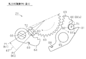
- the locking lever 63 of the present embodiment rotates when the locking lever control piece 71 presses the side wall 81a of the pressing protrusion 81 continuous with the groove 82. Therefore, in the rotation control device 21 of the present embodiment, in the process in which the operation handle 20 is rotated from the neutral position P0 to the pushed-down position P2 (rotation angle ⁇ 2 ′, see FIG. 3), each locking lever 63 is engaged with the pawl. Detach from the car 60.
- each drive lever 64 moves in the circumferential direction on the radially outer side of the ratchet wheel 60 based on the rotation operation in the second direction in which the operation handle 20 is pushed down.
- Each drive lever control piece 72 provided on the bracket 23A comes into contact with each drive lever 64 from the radially inner side.
- each drive lever 64 pressed by each drive lever control piece 72 rotates clockwise in FIG. 24, whereby the operation handle 20 is rotated from the neutral position P0 to the pushed-down position P2.
- Each drive lever 64 is detached from the ratchet wheel 60.
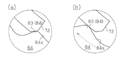
- the drive lever 64 of the present embodiment is provided with a holding engagement portion 83.
- the holding engagement portion 83 is engaged with the drive lever control piece 72 that presses the drive lever 64 when the operation handle 20 is pushed down, thereby holding the state detached from the claw wheel 60.
- each drive lever control piece 72 in contact with each drive lever 64 slides on the contact surface 64s while pressing each drive lever 64.
- the drive lever 64 that rotates integrally with the second operation member 62B moves from the right side to the left side in each drawing.
- the drive lever control piece 72 slides on the contact surface 64s from the left side to the right side in each drawing.
- the holding engagement portion 83 of the present embodiment has a stepped portion 84 that is formed on the contact surface 64s and over which the drive lever control piece 72 can get over.
- the drive lever control piece 72 engages the holding engagement portion 83 at a position where the drive lever control piece 72 rides over the stepped portion 84 from the left side to the right side in each drawing, thereby The disengaged state is maintained.
- the engagement state between the drive lever control piece 72 and the holding engagement portion 83 is such that the drive lever control piece 72 is stepped on the holding engagement portion 83 in the process of returning the operation handle 20 to the neutral position P0. 84 is resolved by moving from the right side to the left side in each figure. Thereby, it shifts to the state which the drive lever 64 and the claw wheel 60 engage.
- each locking lever 63 is engaged with the ratchet wheel 60. .
- the rotation of the ratchet wheel 60 in the direction in which the seat 1 moves downward that is, the rotation of the pinion gear 18 sharing the rotation shaft 22 with the pinion wheel 60 is restricted.
- each locking lever 63 detached from the ratchet wheel 60 is regulated by the contact of each locking lever control piece 71 with each locking lever 63.
- the rotation of the pinion gear 18 in the direction in which the seat 1 moves upward the vertical position of the seat 1 supported by the link mechanism 12 is stably held.
- each drive lever 64 provided integrally with the second operation member 62 ⁇ / b> B moves radially outward of the claw wheel 60. In the figure, it moves in the circumferential direction counterclockwise.
- each of the drive levers 64 is configured to rotationally drive the engaged ratchet wheel 60 in the direction in which the seat 1 moves upward.
- each locking lever control piece 71 causes each drive lever 64 to rotationally drive the ratchet wheel 60. It is separated from each locking lever 63 before. As a result, rotation drive by each drive lever 64 is started in a state in which each latch lever 63 can be detached from the ratchet wheel 60.
- each drive lever 64 moves in the circumferential direction in the direction opposite to the direction in which the claw wheel 60 is rotationally driven, so that the operation of each drive lever 64 that is detached from the claw wheel 60 is allowed.
- each drive lever 64 is moved from the position N1 corresponding to the pulling position P1 to the neutral position P0 while the rotation position (two teeth) of the ratchet wheel 60 rotated by the single pulling operation is held. Return to the position N0 corresponding to.
- the seat lifter device 10 of the present embodiment rotates the operation handle 20 in the first direction so as to lift the operation handle 20 upward from the neutral position P0, and the operation handle 20 that has been pulled up to the neutral position P0.
- the sheet 1 supported by the link mechanism 12 can be moved upward.
- each locking lever control that moves the radial outer side of the ratchet wheel 60 in the circumferential direction clockwise in each figure.
- each locking lever 63 is detached from the ratchet wheel 60.
- each drive lever 64 moves circumferentially in the clockwise direction in each drawing on the radially outer side of the ratchet wheel 60, so that each drive lever control piece disposed on the radially inner side of each drive lever 64. 72 abuts. Then, each drive lever 64 is detached from the ratchet wheel 60 by being pressed by each drive lever control piece 72.
- the seat lifter device 10 of the present embodiment allows the free rotation of the pinion gear 18 by rotating the operation handle 20 in the second direction and maintaining the input operation of pushing down from the neutral position P0 (push-down position P2). Is done. As a result, the sheet 1 supported by the link mechanism 12 can be moved downward.
- the rotation control device 21 shares a pinion gear 18 and a rotation shaft 22 and rotates integrally with the pinion gear 18 and a rotation operation with respect to the operation handle 20 provided at a position coaxial with the claw wheel 60. And an operation member 62. Further, the rotation control device 21 is engaged with the claw wheel 60 based on the engaging lever 63 that can regulate the rotation of the pinion gear 18 by engaging with the claw wheel 60 and the rotation operation of the operation handle 20 in the first direction.
- a drive lever 64 capable of rotating the pinion gear 18 in a direction in which the seat 1 moves upward by rotating together with the operation member 62 in a combined state.
- the locking lever 63 is configured to be detachable from the ratchet wheel 60 by the rotation of the pinion gear 18 in which the seat 1 moves upward.
- the rotation control device 21 has a locking lever control piece 71 and a driving lever control piece 72 for detaching the locking lever 63 and the driving lever 64 from the ratchet wheel 60 based on the turning operation of the operation handle 20 in the second direction.
- the locking lever control piece 71 is configured to restrict the operation of the locking lever 63 that is detached from the ratchet wheel 60.
- the link mechanism 12 is supported by repeating the first-direction turning operation for pulling up the operation handle 20 at the neutral position P0 and the second-direction turning operation for returning the operation handle 20 to the neutral position P0.
- the sheet 1 can be moved upward.
- the seat 1 can be moved downward only by rotating the operation handle 20 from the neutral position P0 in the second direction and holding the rotation position (pressed position P2).
- the operation of the locking lever 63 that is detached from the claw wheel 60 is restricted, so that the rotation position of the pinion gear 18 that rotates together with the claw wheel 60 is maintained. Is done.
- the vertical position of the sheet 1 supported by the link mechanism 12 can be stably held.
- the pinion gear 18 By disposing a locking lever 63, a driving lever 64, a locking lever control piece 71 and a driving lever control piece 72 for controlling the rotation of the claw wheel 60 on the radially outer side of the claw wheel 60, the pinion gear 18
- the dimension in the direction along the rotation shaft 22 can be shortened.
- the rotation control device 21 can be reduced in size, and the mountability of the rotation control device 21 on the side of the seat can be improved.
- the ratchet wheel 60 and the locking lever 63 and the ratchet wheel 60 and the drive lever 64 form a plurality of independent ratchet mechanisms, so that, for example, an external force acts on the seat 1 and so on. Even when the rotation shaft 22 is tilted, the rotation position can be stably maintained. And thereby, high reliability can be ensured.
- the rotation control device 21 has a phase delayed from the first operation member 62A based on the first and second operation members 62A and 62B provided to be relatively rotatable and the rotation operation of the operation handle 20.
- the torsion coil springs 68 and 69 that urge the coupling mechanism 32 that can rotate the second operation member 62B, and the latch lever 63 and the drive lever 64 to engage the lever 63 and 64 with the claw wheel 60.
- the locking lever 63 is pivotally supported by a support shaft 65 provided on the bracket 23 that supports the rotating shaft 22 and is rotatably arranged on the radially outer side of the ratchet wheel 60.
- the operation member 62B By being pivotally supported by a support shaft 65 provided on the operation member 62B, the operation member 62B is rotatably arranged on the radially outer side of the ratchet wheel.
- the locking lever control piece 71 is provided on the first operation member 62 ⁇ / b> A, and the drive lever control piece 72 is provided on the bracket 23.
- the locking lever control piece 71 abuts on the locking lever 63 that engages with the ratchet wheel 60 and restricts the rotation of the locking lever 63.
- the first operating member 62 ⁇ / b> A and the bracket 23 are rotated relative to each other based on the rotating operation in two directions, thereby pressing the locking lever 63 and rotating it in the direction of detachment from the ratchet wheel 60.
- the drive lever control piece 72 presses the drive lever 64 and detaches from the ratchet wheel 60 by the relative rotation of the second operation member 62B and the bracket 23 based on the rotation operation in the second direction. Rotate in the direction.
- the locking lever control piece 71 when the operation handle 20 is in the neutral position P0, the locking lever control piece 71 is brought into contact with the locking lever 63 to restrict the rotation of the locking lever 63.
- the rotation of the locking lever 63 is restricted, and the locking lever 63 cannot be detached from the claw wheel 60, so that the rotation position of the pinion gear 18 that rotates integrally with the claw wheel 60 is maintained.
- the locking lever control piece 71 is separated from the locking lever 63 based on the phase difference between the first and second operating members 62A and 62B, the locking lever In a state where 63 can be detached from the claw wheel 60, the driving lever 64 starts to rotate the claw wheel 60.
- the locking lever control piece 71 after the locking lever control piece 71 is separated from the locking lever 63 based on the phase difference between the first and second operating members 62A and 62B, the locking lever In a state where 63 can be detached from the claw wheel 60, the driving lever 64 starts to rotate the claw wheel 60.
- the locking lever 63 includes a restricting protrusion 80 that protrudes radially outward of the ratchet wheel 60 in the engaged state with the ratchet wheel 60.
- the locking lever control piece 71 comes into contact with the tip 80a of the restricting protrusion 80.
- the locking lever control piece 71 can be brought into contact with the locking lever 63 in a limited manner when the operation handle 20 is in the neutral position P0.
- it is possible to reliably hold the rotation position of the claw wheel 60 when the operation handle 20 is in the neutral position P0 without hindering the movement of the claw wheel 60 based on the turning operation of the operation handle 20. it can.
- the locking lever 63 includes a pressing protrusion 81 that protrudes radially outward from the restriction protrusion 80. Then, the locking lever control piece 71 presses the pressing protrusion 81 based on the turning operation of the operation handle 20 in the second direction.
- a plurality of engagement holes 35 extending in the circumferential direction are formed in the first input member 28A constituting the first operation member 62A.
- the engagement protrusion 37 inserted into each of the engagement holes 35 is connected to the connection member 38 that connects the operation plate 61 constituting the second operation member 62B and the second input member 28B so as not to rotate relative to each other. Is formed.
- the coupling mechanism 32 is configured in which the first input member 28A (the disk portion 33 thereof) in which the respective engagement holes 35 are formed is the first engagement body and the coupling member 38 is the second engagement body.
- the engagement holes 35 are filled with a clearance in the circumferential direction so as to close the clearance in the circumferential direction.
- the relative protrusion between the first input member 28A and the second input member 28B is allowed by the relative movement of the engaging protrusions 37.
- the engagement protrusions 37 moved in the engagement holes 35 are engaged with any one of the circumferential end portions, and the torque can be transmitted via the connecting member 38.
- the input member on the side rotates with a delayed phase.
- the rotation torque of the first operation member 62A is not transmitted to the second operation member 62B.
- the second operation member 62B can be rotated with a phase delayed from the first operation member 62A with a simple configuration.
- the rotation control device 21 returns the operation handle 20 to the neutral position, and at the neutral position P0, the engagement protrusion 37 extends from the circumferential end of each engagement hole 35 engaged during the rotation operation. Is provided with a handle return device 31 that defines a relative rotational position of the first operating member 62A and the second operating member 62B so as to be separated from each other.
- the second operation member 62B can be rotated more reliably at a phase delayed from the first operation member 62A. Further, by defining the relative positions of the first and second operation members 62A and 62B at the neutral position P0, each component of the rotation control device 21 can be returned to an appropriate position. And thereby, reliable operation
- the drive lever 64 includes a holding engagement portion 83 that can hold the state detached from the ratchet wheel 60 by engaging with the drive lever control piece 72 that presses the drive lever. According to the above configuration, it is possible to create a so-called “for” movement of the drive lever 64. As a result, the state in which the drive lever 64 is engaged with the ratchet wheel 60 and the state in which the engagement is released can be clearly separated. As a result, interference between the ratchet wheel 60 and the drive lever 64 at the time of transition between the engaged state and the non-engaged state can be reduced, and a smoother operation can be ensured.
- the first bracket 23 ⁇ / b> A is formed with a long hole 76 that guides the locking lever control piece 71 by inserting the locking lever control piece 71.
- the support rigidity of the locking lever control piece 71 can be increased.
- the shaft-like member 74 constituting the locking lever control piece 71 is supported by the first operating member 62A with its base end cantilevered, so that its distal end 74a is supported by the wall surface of the long hole 76.
- a more remarkable effect can be obtained.
- the locking lever 63 can be pressed more reliably.
- the support shaft 65 of the latch lever 63 and the support shaft 66 of the drive lever 64 are the engagement surface S1 between the latch lever 63 and the ratchet 60 and the engagement surface S2 between the drive lever 64 and the ratchet wheel 60. Are arranged in directions intersecting with each other. By setting it as such a structure, a ratchet mechanism can be formed between the claw wheel 60 and the latch lever 63, and between the claw wheel 60 and the drive lever 64.
- the spring member 130 constituting the handle return device 131 has a plurality of holes that penetrate the spring body 141 in the radial direction.
- the hole 52 has a circumferential end 52a that functions as a first intermediate engagement portion 58 with which the engagement protrusion 53 can be engaged.
- the spring member 130 of this embodiment further includes a hole 92 formed at a position different from the hole 52 in the circumferential direction of the spring main body 141.
- the hole 52 is formed at a position close to the second end 141b in the circumferential direction of the spring body 141.
- the hole 92 is formed at a position close to the first end 141a.
- the hole 92 also has a long hole shape extending in the circumferential direction. The circumferential length of the hole 92 is set shorter than the hole 52.
- the first intermediate engagement portion 58 of the hole 52 and the second intermediate engagement portion 58b of the hole 92 are used as both spring ends SP1 and SP2.
- the third spring portion 55c is provided.
- the third spring portion 55c is a second spring portion having the first intermediate engagement portion 58 of the hole portion 52 as one of the spring end portions SP1 and SP2 due to the short effective spring length L3.
- it functions as a reinforcing spring part capable of generating a larger return force than the first spring part 55a as a basic spring part having two end engaging parts 56 as both spring end parts SP1, SP2. .
- the handle return device 131 of the present embodiment provides the first to third return forces in the direction for returning the operation handle 20 to the neutral position P0 based on the direction of the rotation operation input to the operation handle 20. It can be generated by any one of the spring portions 55a to 55c.
- the first implementation is performed when the operation handle 20 is rotated in the first direction, that is, when an input operation is performed to pull the operation handle 20 upward from the neutral position P0.
- the first spring portion 55a generates a return force that returns the operation handle 20 to the neutral position P0.
- the second input member 128B rotates at a phase delayed from the first input member 128A.
- the first The engaging protrusion 48 provided on the input member 128A engages with the terminal engaging portion 56 of the first end portion 141a.
- the spring member 130 is pressed in the counterclockwise direction, that is, in the first direction in each figure, so that the engagement protrusion 93 and the circumferential end 92a of the hole 92 are separated from each other. It becomes a state. In the handle returning device 131 of the present embodiment, this separated state is maintained even at the pulling position P1 where the maximum operation amount ⁇ 1 of the operation handle 20 in the first direction is generated.
- the first and second input members 128A and 128B are generated by the spring member 130. Based on the return force to be rotated, in each figure, the lens rotates clockwise, that is, in the second direction.
- the handle returning device 131 of the present embodiment at this time, the engaging protrusion 93 provided on the second input member 128B comes into contact with the circumferential end 92a of the hole 92. That is, at the time of a return operation for returning the operation handle 20 rotated in the first direction to the neutral position P0, the second intermediate engagement portion 58b of the hole 92 is provided as the first spring end SP1, and the spring The third spring portion 55c having the terminal engaging portion 56 of the second end portion 141b of the main body 141 as the second spring end portion SP2 is elastically deformed. Then, the handle return device 131 of the present embodiment returns the operation handle 20 to the neutral position P0 based on the return force generated by the elastically deformed third spring portion 55c.
- the first intermediate engagement portion 58 of the hole 52 is provided as the first spring end SP1 as in the first embodiment
- the second spring portion 55b having the terminal engagement portion 56 of the first end portion 141a as the second spring end portion SP2 generates a return force that returns the operation handle 20 to the neutral position P0.
- the reinforced spring portion with a short effective spring length L that is, with a large spring force, at the time of a return operation for returning the operation handle 20 rotated in the first direction to the neutral position P0.
- “F1” is the maximum value of the return force F during the input operation using the first spring portion 55a
- “F1 ′” is during the return operation using the third spring portion 55c. This is the maximum value of the return force F (F1 ′> F1).
- the returnability of the operation handle 20 to the neutral position P0 can be enhanced.
- the relative positions of the first and second input members 128A and 128B at the neutral position P0 are defined with high accuracy, and each component of the rotation control device 21 is returned to an appropriate position. The reliable operation of the two input members 128A and 128B can be ensured.
- F1 ′ can be set to different values.
- the return at the time of the return operation is performed.
- the relative positions of the first and second input members 128A and 128B can be defined more accurately. And thereby, the reliable operation
- the sector gear 16 having the rotation point at the connection point X2 between the side frame 13 and the rear link 15 is provided for the rear link 15 connected to the right side frame 13.
- the present invention is not limited to this, and a configuration in which the sector gear 16 is provided on another link member 11 may be employed.
- the connection point (X3, X4) of 8 and the link member 11 may be sufficient.
- the two link members 11 form a known parallel link mechanism.
- the present invention is not limited to this, and the form of the link mechanism includes the number of link members 11 as long as the seat 1 supported above can be moved up and down based on the rotation of each link member 11. Any change may be made.
- the operation handle 20 is fixed to the operation member 62 (first operation member 62A).
- the operation member 62 rotates integrally with the operation handle 20 when the operation handle 20 is rotated.
- the present invention is not limited to this, and for example, a configuration in which the operation handle 20 and the operation member 62 are connected via a gear or the like may be employed.
- the operation handle 20 and the operation member 62 are not necessarily arranged coaxially.
- the rotation operation for pulling up the operation handle 20 is the rotation operation in the first direction
- the rotation operation for pushing the operation handle 20 downward is the rotation operation in the second direction.
- the present invention is not limited to this, and a rotation operation that pushes down the operation handle 20 is a rotation operation in the first direction, and a rotation operation that pulls the operation handle 20 upward is a rotation operation in the second direction. May be.
- the first bracket 23A fixed to the side frame 13 and the second bracket 23B provided to face the first bracket 23A are provided.
- the first bracket 23A and the second bracket 23B are each formed by plastic processing (pressing) a metal plate material.
- the present invention is not limited to this, and the configuration of the bracket 23 such as the number, shape, and material of the bracket 23 may be arbitrarily changed. Further, for example, a configuration may be employed in which the long hole 76 through which the locking lever control piece 71 is inserted is not formed in the first bracket 23A.
- the second operation member 62B is rotated at a phase delayed from the first operation member 62A during the rotation operation in the first direction to pull up the operation handle 20 at the neutral position P0.
- the present invention is not limited to this, and the second operation member 62B is positively delayed from the first operation member 62A in the second direction of rotation operation in which the operation handle 20 at the neutral position P0 is pushed down. You may make it rotate.
- the engagement holes 35 that are engaged when the operation handle 20 is rotated in the first direction in the engagement holes 35 that constitute the coupling mechanism 32 at the neutral position P0, the engagement holes 35 that are engaged when the operation handle 20 is rotated in the first direction in the engagement holes 35 that constitute the coupling mechanism 32.
- the relative rotation positions of the first operation member 62A and the second operation member 62B are defined so that the respective engagement protrusions 37 are separated from the circumferential end 35a.
- the present invention is not limited to this, and at the neutral position P0, the engagement protrusions 37 are also separated from the circumferential ends 35b of the engagement holes 35 that are engaged when the operation handle 20 is rotated in the second direction. You may make it do.
- the second operation member 62B can be reliably rotated at a phase delayed from the first operation member 62A.
- the second operation member 62B may be rotated without delay from the first operation member 62A. Note that this can be easily realized by configuring each engagement protrusion 37 to contact the circumferential end 35b of each engagement hole 35 at the neutral position P0.
- the first input member 28A (128A) having a plurality (three) of the engagement holes 35 is provided as the first engagement body, and is connected to the second input member 28B (128B).
- the connection mechanism 32 is configured by providing the member 38 as the second engagement body.
- the present invention is not limited to this, and the second input member 28B is provided as a first engagement body having a plurality of engagement holes, and the first input member 28A is engaged with the engagement holes. You may provide as a 2nd engaging body which has a part.
- the structure by which the connection mechanism 32 is formed of the 1st engagement body and 2nd engagement body which were formed separately from 1st and 2nd input member 28A, 28B may be sufficient.
- the coupling mechanism 32 may be formed by a configuration other than the engagement between the engagement hole 35 and the engagement protrusion 37 as long as the connection mechanism 32 can be rotated by the rotation.
- the handle return device 31 (131) returns the rotated operation handle 20 to the neutral position P0 based on the elastic force of the spring member 30 (130) formed as a so-called ring spring. It was decided.
- the present invention is not limited to this, and the configuration of the handle return device 31 including the spring member 30 may be arbitrarily changed.
- the structure which uses the normal spring member in which the spring main body itself comprises one spring part may be sufficient.
- the shape of the spring member 30 (130) may be arbitrarily changed.
- the shape of the spring body 41 (141) does not necessarily have to be substantially C-shaped, and may be a polygonal bent shape.
- the hole 52 may be formed by notching the end in the width direction of the spring member 30 (130).
- middle engagement part in the spring main body may be sufficient.
- the shape of the locking lever 63 including the restricting protrusion 80 and the pressing protrusion 81 may be arbitrarily changed. Further, the shape of the drive lever 64 may be arbitrarily changed including the holding engagement portion 83.
- the rotation control device 21 has the first and second operation members 62A and 62B.
- the present invention is not limited to this, and the configuration may be such that the locking lever 63, the driving lever 64, the locking lever control piece 71, and the driving lever control piece 72 operate when one operating member 62 rotates. . If smooth movement of the ratchet wheel 60 is taken into consideration, the locking lever 63 and the ratchet wheel are utilized using the phase difference between the first and second operation members 62A and 62B as in the above embodiments. It is desirable to avoid interference with 60.
- the two sets of the locking lever 63, the driving lever 64, the locking lever control piece 71, and the driving lever control piece 72 are provided, but the locking lever 63, the driving lever 64, the locking lever
- the number of sets of the lever control piece 71 and the drive lever control piece 72 may be one set or three or more sets.
- the plurality of sets of the locking lever 63, the driving lever 64, the locking lever control piece 71, and the driving lever control piece 72 are not necessarily arranged at equal intervals.
Landscapes
- Engineering & Computer Science (AREA)
- Aviation & Aerospace Engineering (AREA)
- Transportation (AREA)
- Mechanical Engineering (AREA)
- Seats For Vehicles (AREA)
Abstract
回転制御装置(21)は、爪車(60)に係合することによりピニオンギヤの回転を規制可能な係止レバー(63)と、第1方向への操作ハンドルの回動操作に基づき爪車(60)に係合する状態で操作部材と一体に回動することによりシートが上方移動する方向にピニオンギヤを回転駆動する駆動レバー(64)とを備える。係止レバー(63)は、シートが上方移動する際のピニオンギヤの回転により爪車(60)から脱離する。回転制御装置(21)は更に、第2方向への操作ハンドルの回動操作に基づき爪車(60)から係止レバー(63)及び駆動レバー(64)を脱離させる係止レバー制御片(71)及び駆動レバー制御片(72)を備える。操作ハンドルが中立位置にある場合には、爪車(60)から脱離する係止レバー(63)の動作を係止レバー制御片(71)が規制する。
Description
本発明は、車両用シートリフター装置に関するものである。
一般に、上下方向における車両用シートの位置調整を可能とするシートリフター装置は、回動可能に設けられたリンク部材を介して上方にシートを支持するリンク機構を備えている。また、多くの場合、その何れかのリンク部材には、共通の回動軸を有して当該リンク部材と一体に回動するセクターギヤが設けられている。そして、このセクターギヤを介して伝達される駆動力に基づきリンク部材が回動することによって、そのリンク機構の上方に支持されたシートを昇降動作させることが可能となっている。
例えば、特許文献1に記載のシートリフター装置は、セクターギヤに噛合されたピニオンギヤと、そのピニオンギヤと同軸に設けられた操作ハンドルと、を備えている。また、これらピニオンギヤと操作ハンドルとの間には、同軸に並置された二つのクラッチ部を有した回転制御装置が設けられている。そして、この回転制御装置により、その操作ハンドルに入力される往復回動操作に基づいてピニオンギヤを回転駆動し、及びその回転位置を保持することが可能となっている。
しかしながら、上記従来技術では、その同軸に並置された二つのクラッチ部が、シート側方への回転制御装置及び操作ハンドルの搭載性を低下させている。そして、回転制御装置の構造も複雑であり小型化が難しいことから、この点において、なお改善の余地を残すものとなっていた。
本発明は、上記問題点を解決するためになされたものであって、その目的は、簡素な構成にて、小型化可能な回転制御装置を備えた車両用シートリフター装置を提供することにある。
本発明の一態様による車両用シートリフター装置は、回動可能に設けられたリンク部材を介して上方にシートを支持するリンク機構と、前記リンク部材と回動軸を共有して一体に回動するセクターギヤと、前記セクターギヤに歯合するピニオンギヤと、中立位置を有して第1方向及び第2方向に回動操作される操作ハンドルと、前記ピニオンギヤと前記操作ハンドルとの間に介在された回転制御装置と、を備え、前記回転制御装置は、前記ピニオンギヤと回転軸を共有して一体に回転する爪車と、前記爪車と同軸位置に設けられて前記回動操作に基づき回動する操作部材と、前記爪車に係合することにより前記ピニオンギヤの回転を規制可能な係止レバーと、前記第1方向への前記操作ハンドルの回動操作に基づき前記爪車に係合する状態で前記操作部材と一体に回動することにより前記シートが上方移動する方向に前記ピニオンギヤを回転駆動する駆動レバーと、を備え、前記係止レバーは、前記シートが上方移動する際の前記ピニオンギヤの回転により前記爪車から脱離するものであって、前記回転制御装置は更に、前記第2方向への前記操作ハンドルの回動操作に基づき前記爪車から前記係止レバー及び前記駆動レバーを脱離させる係止レバー制御片及び駆動レバー制御片を備えるとともに、前記操作ハンドルが前記中立位置にある場合には、前記爪車から脱離する前記係止レバーの動作を前記係止レバー制御片が規制する。
[第1の実施形態]
以下、車両用シートリフター装置に関する第1の実施形態を図面に従って説明する。
図1に示すように、車両用のシート1は、シートクッション2と、このシートクッション2の後端部に対して傾動自在に設けられたシートバック3と、を備えている。
以下、車両用シートリフター装置に関する第1の実施形態を図面に従って説明する。
図1に示すように、車両用のシート1は、シートクッション2と、このシートクッション2の後端部に対して傾動自在に設けられたシートバック3と、を備えている。
図2及び図3に示すように、本実施形態では、図示しない車両の床部には、ブラケット4上に支持された左右一対のロアレール5が設けられている。また、これらのロアレール5には、当該各ロアレール5上を相対移動するアッパレール6が装着されている。そして、シート1は、これら各アッパレール6上に支持されている。
即ち、本実施形態では、相対移動可能に設けられたロアレール5及びアッパレール6によって、シートスライド装置7が形成されている。そして、車両の乗員は、このシートスライド装置7の機能を利用することにより、車両前後方向(図2中、左右方向)におけるシート1の位置調整を行うことができるようになっている。
また、本実施形態のシート1は、シートリフター装置10を介して各アッパレール6に固定されている。そして、車両の乗員は、このシートリフター装置10の機能を利用することにより、その上下方向におけるシート1の位置調整(シートクッション2の高さ調整)を行うことが可能となっている。
シートリフター装置10は、回動自在に設けられた2つのリンク部材11を介して上方にシート1を支持するリンク機構12を備えている。2つのリンク部材11のうちの一方は、シートクッション2の骨格を構成するサイドフレーム13の前端部13a及びアッパレール6に設けられた支持部材8の前端部8aに対して回動可能に連結された前方リンク14として設けられている。他方のリンク部材11は、サイドフレーム13の後端部13b及び支持部材8の後端部8bに対して回動可能に連結された後方リンク15として設けられている。即ち、本実施形態のリンク機構12には、周知の平行リンク機構が用いられている。そして、これら各リンク部材11の回動に基づいて、その上方に支持するシート1を昇降動作させることが可能となっている。
尚、図2に示すように、本実施形態では、サイドフレーム13に対する前方リンク14及び後方リンク15の各連結点X1,X2は、支持部材8に対する前方リンク14及び後方リンク15の各連結点X3,X4よりも車両後方側に配置されている。即ち、リンク機構12の上方に支持されたシート1は、サイドフレーム13と各リンク部材11との各連結点X1,X2が車両前方側に移動するように各リンク部材11が回動することによって、上方移動する。そして、各連結点X1,X2が車両後方側に移動するように各リンク部材11が回動することによって、下方移動するようになっている。
また、本実施形態では、上記リンク機構12を構成する上記2つのリンク部材11のうちの一つであって、右側のサイドフレーム13に連結される後方リンク15には、その連結点X2を回動中心とするセクターギヤ16が形成されている。即ち、このセクターギヤ16は、後方リンク15と回動軸Q1を共有して一体に回動する。尚、本実施形態では、左右のサイドフレーム13(の後端部13b)間を連結するトルクロッド17が後方リンク15の回動軸Q1を構成する。そして、本実施形態のリンク機構12は、このセクターギヤ16を介して後方リンク15が駆動されることにより、その上方に支持されたシート1を昇降動作させることが可能となっている。
図3及び図4に示すように、本実施形態では、サイドフレーム13のシート幅方向外側(図3中、紙面手前側)には、シート1を昇降動作させるべく回動操作される操作ハンドル20が設けられている。また、図2に示すように、上記セクターギヤ16には、ピニオンギヤ18が噛合されている。そして、図2及び図4に示すように、これらのピニオンギヤ18と操作ハンドル20との間には、回転制御装置21が介在されている。
即ち、操作ハンドル20に入力される操作トルクは、回転制御装置21を介してピニオンギヤ18に伝達される。詳しくは、後述する操作ハンドル20の引き上げ動作に伴う操作トルクがピニオンギヤ18に伝達される。そして、本実施形態では、回転制御装置21により、ピニオンギヤ18の回転を制御することで、リンク機構12の上方に支持されたシート1の上下位置を調整することが可能となっている。
(回転制御装置及びハンドル戻し装置)
次に、本実施形態のシートリフター装置10に設けられた回転制御装置21及びハンドル戻し装置31の構成について説明する。
次に、本実施形態のシートリフター装置10に設けられた回転制御装置21及びハンドル戻し装置31の構成について説明する。
図4~図8に示すように、本実施形態の回転制御装置21は、一端に上記ピニオンギヤ18が設けられた回転軸22と、この回転軸22を回転自在に支持するブラケット23と、を備えている。
本実施形態のブラケット23は、上記のようにシートクッション2の骨格を構成するサイドフレーム13、詳しくは、その外側面13cに固定される第1ブラケット23Aと、当該第1ブラケット23Aに対向して設けられた第2ブラケット23Bと、を備えている。尚、本実施形態では、これら第1ブラケット23A及び第2ブラケット23Bは、金属製の板材を塑性加工(プレス加工)することにより形成されている。また、これら第1ブラケット23A及び第2ブラケット23Bには、それぞれ、互いに対向する貫通孔25a,25bが形成されている。そして、上記回転軸22は、これらの貫通孔25a,25bに挿通された状態で回動自在に支持されている。
ここで、本実施形態のサイドフレーム13には、上記ピニオンギヤ18が設けられた回転軸22の第1端部22aを挿入可能な貫通孔26が形成されている。そして、本実施形態では、この貫通孔26を介することにより、ピニオンギヤ18を、サイドフレーム13の内側面13dに隣接して設けられたセクターギヤ16に対して噛合させることが可能となっている(図2参照)。
また、本実施形態の回転制御装置21は、上記操作ハンドル20に連動して回動する入力部材28と、操作ハンドル20に対する回動操作に基づき弾性変形するように構成されたバネ部材30と、を備えている。そして、本実施形態では、このバネ部材30が発生する戻し力(弾性力)に基づき入力部材28を付勢することによって、その回動操作された操作ハンドル20を中立位置P0に復帰させることが可能なハンドル戻し装置31が回転制御装置21に備えられている。
図3及び図4に示すように、本実施形態の操作ハンドル20は、その先端に設けられたハンドル部20aが車両前方側に向かって延びるレバー形状を有している。そして、この操作ハンドル20においては、ハンドル部20aが車両の床部に対して略水平となる位置が中立位置P0として設定されている。ハンドル部20aの基端は、回転制御装置21に連結されている。
本実施形態のシートリフター装置10において、操作ハンドル20は、その先端に設けられたハンドル部20aを上方に引き上げる方向(第1方向)、又は下方に押し下げる方向(第2方向)に回動操作される。そして、操作入力のない場合には、ハンドル戻し装置31の機能によって、当該操作ハンドル20は回動操作の基準となる上記の中立位置P0に復帰する。
図7~図11に示すように、本実施形態のハンドル戻し装置31は、相対回動可能に同軸配置された第1及び第2の入力部材28A,28Bを備えている。また、本実施形態のハンドル戻し装置31は、これら第1の入力部材28Aと第2の入力部材28Bとの間をトルク伝達可能に連結する連結機構32を備えている。そして、本実施形態では、第1の入力部材28Aに対して上記操作ハンドル20が固定されるようになっている。
尚、本実施形態では、これら第1及び第2の入力部材28A,28Bは、金属製の板材を塑性加工(プレス加工)することにより形成されている。また、これら第1及び第2の入力部材28A,28Bは、それぞれ、その中心部に円孔33a,34aを有した円板部33,34を備えている。円板部33,34の各々は円形部の一例である。そして、その円孔33a,34a内に上記回転軸22の第2端部22bが挿通されることにより、支持軸Q2としての回転軸22に第1及び第2の入力部材28a,28bが相対回動可能に軸支されている。
また、第1及び第2の入力部材28A,28Bの円板部33,34には、それぞれ、その円孔33a,34aの径方向外側において周方向に延びる複数(本実施形態では各3つ)の係合孔35,36が形成されている。本実施形態では、各係合孔35,36は、略円弧状の長孔形状を有し、係合孔35は円孔33aの周りに均等間隔で形成され、係合孔36は円孔34aの周りに均等間隔で形成されている。そして、本実施形態のハンドル戻し装置31は、これら第1の入力部材28A及び第2の入力部材28Bの係合孔35,36の双方に係合する複数(本実施形態では3つ)の係合突部37を有した連結部材38を備えている。
本実施形態では、この連結部材38は、略円筒状の外形を有している。また、各係合突部37は、回転軸22の第2端部22b(図7及び図8中、上側)に隣接して配置される一方側の端部(第2端部38b)を周方向に沿って均等間隔で切り欠くことにより形成されている。そして、各係合突部37は、上記第1の入力部材28A及び第2の入力部材28Bの各係合孔35,36と同様、周方向に延びる円弧状の断面を有している。
また、本実施形態では、この連結部材38は、その筒内に回転軸22が挿通されることにより当該回転軸22と同軸に配置されている。つまり、連結部材38は、上記第2ブラケット23Bに形成された貫通孔25bに挿通されている。そして、各係合突部37は、第2ブラケット23Bに近い側に位置する第2の入力部材28B(図7及び図8中、下側)とともに第1の入力部材28Aを貫通する態様で、これら第1及び第2の入力部材28A,28Bの係合孔35,36の双方に挿入されるようになっている。
また、本実施形態のハンドル戻し装置31は、略円板状の取付部材39を備えている。取付部材39は、回転軸22の第2端部22bが挿通される挿通孔39aと、上記係合孔35,36の双方に挿通された各係合突部37の先端に嵌合する複数(本実施形態では、3つ)の嵌合孔39bとを有している。そして、本実施形態では、この取付部材39と第2ブラケット23Bとの間、詳しくは、第2ブラケット23Bの貫通孔25bに取着された摺動プレート40(図5参照)と取付部材39との間に、第1及び第2の入力部材28A,28Bの円板部33,34を挟み込むことによって、これら第1及び第2の入力部材28A,28Bの軸方向移動を規制する構成になっている。
ここで、図11に示すように、第2の入力部材28Bの円板部34に形成された各係合孔36の周方向長さは各係合突部37の周方向長さと略等しく設定されている。これにより各係合孔36内における各係合突部37の相対的な周方向移動が規制されることで、第2の入力部材28Bと連結部材38とが相対回動不能に連結されるようになっている。
一方、図10に示すように、第1の入力部材28Aの円板部33に形成された各係合孔35の周方向長さは各係合突部37の周方向長さよりも長く設定されている。即ち、その周方向において各係合孔35内を各係合突部37が相対移動することが可能となっている。これにより、第1の入力部材28Aと第2の入力部材28Bとをトルク伝達可能に連結するとともに、第1及び第2の入力部材28A,28Bのうちの一方に対して他方を遅れた位相で回動させることが可能な連結機構32が形成されている。
即ち、本実施形態の連結機構32では、第1及び第2の入力部材28A,28Bの係合孔35,36内に挿入された各係合突部37が、第1及び第2の入力部材28A,28Bの双方に対して周方向移動不能に係合することによって、連結部材38を介して、第1及び第2の入力部材28A,28Bのうちの一方に入力された回動トルクを他方に伝達することが可能となっている。
しかしながら、図12(a)(b)に示すように、本実施形態の連結機構32においては、その周方向長さの違いに基づいて第1の入力部材28Aの各係合孔35と各係合突部37との間に周方向隙間が僅かに形成されるようになっている。このため、第1及び第2の入力部材28A,28Bの一方に回動トルクが入力された場合には、その周方向隙間を詰めるように各係合孔35内を各係合突部37が相対移動することにより、第1の入力部材28Aと第2の入力部材28Bとの間の相対回動が僅かに許容される。そして、その後、各係合孔35内を移動した各係合突部37が周方向端部35a,35bのうちの何れか一方に係合し、連結部材38を介してトルク伝達可能な状態になることによって、第1及び第2の入力部材28A,28Bのうちの一方から他方が遅れた位相で、第1及び第2の入力部材28A,28Bが回動するようになっている。
具体的には、図12(a)に示すように、本実施形態のハンドル戻し装置31において、第1の入力部材28Aは、上記操作ハンドル20が第1方向に回動操作された場合には、同図中、反時計回りに回動する。このとき、連結部材38は、各係合突部37が各係合孔35の第1周方向端部35aに係合することにより、第1方向の回動トルクを第2の入力部材28Bに伝達可能な状態となる。そして、本実施形態の連結機構32は、各係合突部37が第1周方向端部35aに係合するまでの間、各係合孔35内を各係合突部37が移動する角度分に相当する遅れた位相で、第2の入力部材28Bを第1方向に回動させることが可能となっている。
一方、図12(b)に示すように、操作ハンドル20が第2方向に回動操作された場合、第1の入力部材28Aは、同図中、時計回りに回動する。このとき、連結部材38は、各係合突部37が各係合孔35の第2周方向端部35bに係合することにより、第2方向の回動トルクを第2の入力部材28Bに伝達可能な状態となる。そして、本実施形態の連結機構32は、各係合突部37が第2周方向端部35bに係合するまでの間、各係合孔35内を各係合突部37が移動する角度分に相当する遅れた位相で、第2の入力部材28Bを第2方向に回動させることが可能となっている。
また、図6~図11に示すように、本実施形態のハンドル戻し装置31は、上記第1及び第2の入力部材28A,28Bの支持軸Q2を構成する回転軸22周りに延在するバネ本体41を有したバネ部材30を備えている。本実施形態では、このバネ部材30は、略円弧状(略C字状)に湾曲したバネ本体41を有する所謂リングバネとして形成されている。そして、バネ部材30は、回転軸22の軸線方向において、第1の入力部材28Aと上記第2ブラケット23Bとの間に配置されている。
本実施形態のハンドル戻し装置31において、第1の入力部材28Aは、上記円板部33の径方向外側に延設された円環部42と、この円環部42の外周縁から回転軸22の軸線方向に上記第2ブラケット23B(図7及び図8中、下側)に向かって延設された複数の折曲部43とを備えている。また、本実施形態の第1の入力部材28Aでは、各折曲部43が円板部33の径方向外側に配置されるように、当該円板部33と円環部42とが段違いに形成されている。更に、本実施形態の第2の入力部材28Bは、その径方向外側が上記各折曲部43に包囲されるように、第1の入力部材28Aよりも小径に形成されている。そして、本実施形態のバネ部材30は、そのバネ本体41が第2の入力部材28Bの径方向外側を囲むように、各折曲部43の内側に配置されている。
また、本実施形態のバネ部材30は、その略C字状の外形を有するバネ本体41の周方向において、それぞれ離間した位置に設けられた複数の係合部(56,58)を備えている。そして、本実施形態では、上記第2ブラケット23B、並びに上記第1及び第2の入力部材28A,28Bには、それぞれ、上記操作ハンドル20の回動操作に基づいて、そのバネ部材30の各係合部(56,58)に係合可能な係合突部(47~49,53)が形成されている。
例えば、本実施形態のバネ部材30は、バネ本体41の両端部41a,41bから径方向内側に折り曲げられた折曲部46a,46bを有している。各折曲部46a,46bは端末係合部56として設けられている。そして、第2ブラケット23B、並びに第1及び第2の入力部材28A,28Bには、それぞれ、折曲部46a,46bの間に配置されることによりバネ部材30に係合可能な係合突部47~49が設けられている。
図9に示すように、第2ブラケット23Bの係合突部47は、上記第1の入力部材28Aの円環部42に対向する略円板状のブラケット本体50の一部を、第1の入力部材28Aに向かって折り曲げることにより形成されている。また、第1の入力部材28Aの係合突部48は、円環部42の一部を第2ブラケット23Bに向かって折り曲げることにより形成されている。更に、第2の入力部材28Bは、円板部34から径方向外側に延びる複数の延伸部51a~51cを有している。そして、第2の入力部材28Bの係合突部49は、第1延伸部51aの先端を第1の入力部材28Aに向かって折り曲げることにより形成されている。
図10に示すように、本実施形態では、第2ブラケット23Bの係合突部47が最も径方向外側に配置されている。そして、第1の入力部材28Aの係合突部48を挟んで、第2の入力部材28Bの係合突部49が最も径方向内側に配置されるようになっている。
また、図9及び図10に示すように、バネ部材30のバネ本体41には、当該バネ本体41を径方向に貫通する孔部52が形成されている。この孔部52は、周方向に延びる長孔形状を有している。また、第1の入力部材28Aには、この孔部52内に挿入される係合突部53が設けられている。そして、本実施形態では、孔部52の周方向端部52aがバネ本体41の両端部41a,41b間に形成された中間係合部58として設けられることで、孔部52内に挿入された係合突部53がバネ部材30に係合するようになっている。
即ち、図13に示すように、バネ本体41は、複数(本実施形態では2つ)のバネ部55a,55bを含む。各バネ部55a,55bは、バネ本体41に形成された複数の係合部56,58(46a,46b,52a)のうち周方向に離間した所与の二つを第1及び第2のバネ端部SP1,SP2として有する。本実施形態では、折曲部46a,46bが、第1のバネ部55aの第1及び第2のバネ端部SP1,SP2として設定されている。また、折曲部46a及び周方向端部52aが、第2のバネ部55bの第1及び第2のバネ端部SP1,SP2として設定されている。従って、各バネ部55a,55bは、異なる有効バネ長L(両バネ端部SP1,SP2間の長さ)を有している。そして、本実施形態のハンドル戻し装置31は、操作ハンドル20に入力される回動操作の方向に応じて、当該操作ハンドル20を中立位置P0に復帰させる戻し力を、第1及び第2のバネ部55a,55bのうちの何れかによって発生することが可能となっている。
詳述すると、図14及び図15に示すように、操作ハンドル20が第1方向に操作された場合、第1の入力部材28Aは、各図中、反時計回りに回動する。このとき、第2ブラケット23Bに対する第1の入力部材28Aの相対的な回動位置が変化することで、第2ブラケット23Bの係合突部47と第1の入力部材28Aの係合突部48とが周方向に離間する。これにより、第2ブラケット23Bの係合突部47及び第1の入力部材28Aの係合突部48が、それぞれ、バネ本体41の両端部41a,41bに設けられた端末係合部56としての各折曲部46a,46bに係合する。
具体的には、操作ハンドル20に連動して回動する第1の入力部材28Aの係合突部48は、当該係合突部48よりも反時計回り方向、即ち第1方向側に配置された第1端部41aの折曲部46aに係合する。また、これによりバネ部材30が第1の入力部材28Aとともに第1方向に回動しようとすることで、第2ブラケット23Bの係合突部47は、第1方向に回動しようとするバネ部材30の第2端部41bの折曲部46bに係合する。その結果、バネ部材30は、その端末係合部56を構成する両折曲部46a,46b間が押し広げられるように拡開する。
つまり、図13に示すように、本実施形態では、第1方向への操作ハンドル20の回動操作時、バネ本体41の第1端部41aの折曲部46aを第1のバネ端部SP1として有し、第2端部41bの折曲部46bを第2のバネ端部SP2として有する第1のバネ部55aが弾性変形するようになっている。そして、本実施形態のハンドル戻し装置31は、その弾性変形した第1のバネ部55aが発生する戻し力に基づいて、第1方向に操作された操作ハンドル20を中立位置P0に復帰させることが可能となっている。
一方、図16及び図17に示すように、操作ハンドル20が第2方向に操作された場合、第1の入力部材28Aは、各図中、時計回りに回動する。本実施形態では、このとき、第1の入力部材28Aに設けられた係合突部53が、バネ本体41に設けられた上記孔部52、詳しくは、第2方向側に位置する孔部52の周方向端部52aを中間係合部58として有するバネ部材30に係合する。これによりバネ部材30が第1の入力部材28Aとともに第2方向に回動しようとすることで、第2ブラケット23Bの係合突部47は、第2方向に回動しようとするバネ部材30の第1端部41aの折曲部46aに係合する。
つまり、図13に示すように、本実施形態では、第2方向への操作ハンドル20の回動操作時、中間係合部58としての孔部52の周方向端部52aを第1のバネ端部SP1として有し、端末係合部56としての第1端部41aの折曲部46aを第2のバネ端部SP2として有する第2のバネ部55bが弾性変形するようになっている。そして、本実施形態のハンドル戻し装置31は、その弾性変形した第2のバネ部55bが発生する戻し力に基づいて、第2方向に操作された操作ハンドル20を中立位置P0に復帰させることが可能となっている。
また、本実施形態では、操作ハンドル20が中立位置P0にある場合、第2ブラケット23Bの係合突部47の周方向両側、及び第2の入力部材28Bの係合突部49の周方向両側が、バネ部材30の両折曲部46a,46b間に挟み込まれるようになっている。
即ち、本実施形態のバネ部材30は、操作ハンドル20の非操作時においても、端末係合部56としての両折曲部46a,46bが設けられたバネ本体41の両端部41a,41bを第1及び第2のバネ端部SP1,SP2として有する第1のバネ部55aが戻し力を発生するように構成されている。そして、本実施形態のハンドル戻し装置31は、操作ハンドル20が中立位置P0にある場合における第2ブラケット23B、並びに上記第1及び第2の入力部材28A,28B間の相対的な回動位置を規定する構成となっている。
具体的には、本実施形態のハンドル戻し装置31は、操作ハンドル20が中立位置P0にある場合、その連結機構32を構成する各係合孔35内において、第1方向の回動操作時に係合する第1周方向端部35aから各係合突部37が離間するように、第1及び第2の入力部材28A,28B間の相対的な回動位置を規定するように構成されている。これにより、第1方向の回動操作時、より確実に、操作ハンドル20が固定された第1の入力部材28Aから遅れた位相で第2の入力部材28Bが回動するようになっている(図12(a)(b)参照)。
さらに詳述すると、図3に示すように、本実施形態では、第1方向の回動操作時に発生する操作ハンドル20の最大操作量α1(引き上げ位置P1)と第2方向の回動操作時に発生する操作ハンドル20の最大操作量α2(押し下げ位置P2)とを比較した場合、その第2方向の回動操作時の最大操作量α2の方が、小さくなっている。
この点を踏まえ、本実施形態のバネ部材30には、上記のように、有効バネ長L1,L2の違いにより異なるバネ力が設定された第1及び第2のバネ部55a,55bが一体に形成されている。そして、本実施形態のハンドル戻し装置31は、第1方向の回動操作時には第1のバネ部55aが戻し力を発生し、第2方向の回動操作時には第2のバネ部55bが戻し力を発生することで、回動操作の方向に応じた適切な戻し力を操作ハンドル20に付与することが可能となっている。
即ち、図13に示すように、第1のバネ部55aと第2のバネ部55bとを比較した場合、二つの端末係合部56を両バネ端部SP1,SP2として有する第1のバネ部55aの有効バネ長L1よりも、中間係合部58を両バネ端部SP1,SP2のうちの一方として有する第2のバネ部55bの有効バネ長L2の方が短くなっている(L=L2<L1)。従って、第2のバネ部55bの方が第1のバネ部55aよりも大きなバネ力(ばね定数)を有する構成となっている。つまり、第1のバネ部55aを基本バネ部とした場合、第2のバネ部55bは、その周方向の弾性変形量に応じて、より大きな戻し力を発生することが可能な強化バネ部となっている。
図18に示すように、本実施形態のハンドル戻し装置31は、この第1のバネ部55aと第2のバネ部55bとのバネ力の違いを利用することで、第1方向及び第2方向の何れの回動操作時においても、操作ハンドル20を中立位置P0に復帰させる戻し力F(F1,F2)が略等しくなるように構成されている(F1≒F2)。この構成により、操作ハンドル20の良好な操作性を確保するとともに、中立位置P0への操作ハンドル20の戻り性を高めている。これにより、シートリフター装置10は、ハンドル戻し装置31に連動する各構成要素の確実な動作を担保する。
尚、図18中、回動角度θ1,θ2は、それぞれ、操作ハンドル20の回動操作に基づき回動する第1の入力部材28Aの回動角度を「θ」とした場合において、第1方向及び第2方向の回動操作時に発生する回動角度θの最大値である(図15及び図17参照)。そして、同図中、「F2´」は、第2方向の回動操作時においても第1のバネ部55aが発生する戻し力Fに基づき操作ハンドル20を中立位置P0に復帰させる構成とした場合(従来構成)の最大値である。
図9~図11、及び図13~図17に示すように、本実施形態では、第2ブラケット23Bには、第2の入力部材28Bの径方向外側、詳しくは、その円板部34の径方向外側に位置し、第1の入力部材28Aに向かって突出するストッパ部59が設けられている。尚、このストッパ部59は、ブラケット本体50の一部を切り欠き、その切り欠き部を第1の入力部材28Aに向かって折り曲げることにより形成されている。そして、本実施形態では、このストッパ部59に対し、上記円板部34から径方向外側に突出する第2延伸部51b及び第3延伸部51cの何れかが当接することによって、第2ブラケット23Bの回動が規制される。即ち、第1方向の回動操作時に発生する操作ハンドル20の最大操作量α1、及び第2方向の回動操作時に発生する操作ハンドル20の最大操作量α2がストッパ部59によって規定されるようになっている(図3参照)。
次に、上記ハンドル戻し装置31に連動する回転制御装置21の各構成要素について説明する。
図5、図7、図8及び図19に示すように、本実施形態の回転制御装置21は、ピニオンギヤ18と回転軸22を共有して一体に回転する爪車60を備えている。本実施形態では、この爪車60は、外周に複数の係合爪を形成してなる周知の構成を有して回転軸22と一体に形成されている。尚、ピニオンギヤ18もまた、回転軸22と一体に形成されている。そして、この爪車60は、回転軸22の軸線方向において、上記第1ブラケット23Aと第2ブラケット23Bとの間に配置されている。
図5、図7、図8及び図19に示すように、本実施形態の回転制御装置21は、ピニオンギヤ18と回転軸22を共有して一体に回転する爪車60を備えている。本実施形態では、この爪車60は、外周に複数の係合爪を形成してなる周知の構成を有して回転軸22と一体に形成されている。尚、ピニオンギヤ18もまた、回転軸22と一体に形成されている。そして、この爪車60は、回転軸22の軸線方向において、上記第1ブラケット23Aと第2ブラケット23Bとの間に配置されている。
また、回転軸22の軸線方向において、第2ブラケット23Bと爪車60との間には、上記第1及び第2の入力部材28A,28Bと同じく、支持軸Q2としての回転軸22に回動可能に支持された操作プレート61が設けられている。尚、本実施形態では、この操作プレート61は、金属製の板材を塑性加工(プレス加工)することにより形成されている。また、操作プレート61には、当該操作プレート61を厚み方向に貫通する貫通孔61aが形成されている。そして、操作プレート61は、その貫通孔61a内に回転軸22が挿通されることにより回動自在に軸支されている。
更に、図7、図8及び図20に示すように、本実施形態では、この操作プレート61には、上記のように第1の入力部材28Aと第2の入力部材28Bとの間をトルク伝達可能に連結可能な連結機構32を構成する連結部材38の第1端部38aが接続されている。本実施形態の操作プレート61は、貫通孔61a内に略円筒状をなす連結部材38の第1端部38aが嵌合されることにより、当該連結部材38に対して相対回転不能に連結されている。これにより、操作プレート61は、操作ハンドル20に連動して回動する第1の入力部材28Aから遅れた位相で回動する。
即ち、本実施形態では、操作ハンドル20に固定された第1の入力部材28Aが第1の操作部材62Aを構成し、第2の入力部材28Bに固定された操作プレート61が、第1の入力部材28Aから遅れた位相で回動する第2の操作部材62Bを構成する。そして、本実施形態の回転制御装置21は、操作ハンドル20の回動操作により生ずる操作部材62(62A,62B)と上記ブラケット23(23A,23B)との間の相対的な位置変化に基づいて、ブラケット23にその回転軸22が支持されたピニオンギヤ18の回転を制御する構成となっている。
図5、図7及び図19に示すように、本実施形態の回転制御装置21は、爪車60に係合することによりシート1が下方移動する方向におけるピニオンギヤ18の回転(図19中、爪車60が時計回りに回転する方向)を規制可能な複数(本実施形態では、2つ)の係止レバー63を備えている。そして、本実施形態の回転制御装置21は、更に、爪車60に係合する状態で上記第2の操作部材62Bと一体に回動することにより、操作ハンドル20に入力された第1方向の回動操作に基づいてシート1が上方移動する方向にピニオンギヤ18を回転駆動することが可能な複数(本実施形態では、2つ)の駆動レバー64を備えている。
本実施形態の回転制御装置21は、その両端が上記第1ブラケット23A及び第2ブラケット23Bに支持されることにより回転軸22と略平行に延びる複数(本実施形態では、二本)の支軸65を備えている。また、本実施形態では、二本の支軸65は、爪車60周りの均等間隔となる位置(周方向に180°離間した位置)に設けられている。そして、上記各係止レバー63は、これらの各支軸65に軸支されることにより爪車60の径方向外側において回動可能に設けられている。
また、本実施形態の回転制御装置21は、その一端が上記第2の操作部材62Bを構成する操作プレート61に固定されることにより、上記第1ブラケット23Aに向かって回転軸22と略平行に延びる複数(本実施形態では、二本)の支軸66を備えている。そして、本実施形態では、これらの支軸66もまた、その爪車60周りの均等間隔となる位置(周方向に180°離間した位置)に設けられている。
尚、本実施形態では、これらの各支軸66は、その一方の軸端が操作プレート61に形成された嵌合孔61b(図20参照)に嵌合することにより当該操作プレート61に固定されている。
また、これらの各支軸66は、図19に示されるような操作ハンドル20が中立位置P0に復帰した状態にある場合において、上記ブラケット23(23A,23B)に設けられた各支軸65に対し、その周方向において、それぞれ約90°ずれた位置に配置されている。そして、上記各駆動レバー64は、これらの各支軸66に軸支されることにより爪車60の径方向外側において回動可能に設けられている。
さらに、本実施形態では、各支軸65には付勢部材としての捩りコイルバネ68が嵌装され、各支軸66にも付勢部材としての捩りコイルバネ69が嵌装されている。そして、図21に示すように、各係止レバー63及び各駆動レバー64は、これら各捩りコイルバネ68,69の弾性力に基づいて、その先端に設けられた係合爪70が爪車60(の係合爪)に係合する方向(図19中、反時計回り方向)に回動付勢されている。
ここで、本実施形態では、係止レバー63の支軸65は、当該係止レバー63の係合爪70と爪車60(の係合爪)との係合面S1に交差する略法線方向において、図21中、時計回り方向における爪車60の回転を規制する側に配置されている。また、図21中、時計回り方向における爪車60の回転、即ちシート1が下方移動する方向におけるピニオンギヤ18の回転を規制可能な圧力角が設定されている。
同様に、駆動レバー64の支軸66もまた、当該駆動レバーの係合爪70と爪車60との係合面S2に交差する略法線方向において、図21中、時計回り方向における爪車60の回転を規制する側に配置されている。また、図21中、反時計回り方向に爪車60を回転駆動することが可能な圧力角が設定されている。
即ち、上記のように、本実施形態では、第1及び第2の操作部材62A,62Bは、操作ハンドル20を引き上げる第1方向の回動操作に基づいて(図3参照)、図13中、反時計回り方向に回動する。このとき、本実施形態の駆動レバー64は、第2の操作部材62Bを構成する操作プレート61と一体に回動することにより、支軸66とともに、爪車60の外周に沿って、図19中、反時計回りに周方向移動する。これにより、本実施形態の駆動レバー64は、係合状態にある爪車60を図19中、反時計回り方向、つまりシート1が上方移動する方向に回転駆動することが可能となっている。
また、本実施形態では、各係止レバー63は、爪車60が上記規制方向とは逆向き、即ちシート1が上方移動する方向に回転した場合には、係止レバー63の係合爪70が爪車60(の係合爪)との係合面S1上を滑るように構成されている。同様に、各駆動レバー64もまた、当該駆動レバー64が爪車60を回転駆動する方向とは逆向き(図19中、時計回り方向)に周方向移動した場合、駆動レバー64の係合爪70が爪車60(の係合爪)との係合面S2上を滑るように構成されている。このように、本実施形態では、爪車60と各係止レバー63との間、及び爪車60と各駆動レバー64との間でラチェット機構を構成している。
更に、図5、図8及び図19に示すように、本実施形態の回転制御装置21は、操作ハンドル20を引き下げる第2方向の回動操作に基づいて(図3参照)、爪車60に対する各係止レバー63の係合を解除させる係止レバー制御片71、及び爪車60に対する各駆動レバー64の係合を解除させる駆動レバー制御片72を備えている。
これらの各係止レバー制御片71及び各駆動レバー制御片72は、それぞれ、操作ハンドル20に入力される回動操作に基づき上記第1及び第2の操作部材62A,62Bとブラケット23(23A,23B)とが相対回動することにより、その制御対象となる各係止レバー63及び各駆動レバー64との相対位置が周方向に変化するように構成されている。そして、第2方向への操作ハンドル20の回動操作時には、これらの係止レバー制御片71及び駆動レバー制御片72が、それぞれ、係止レバー63及び駆動レバー64を押圧することにより、当該各係止レバー63及び各駆動レバー64が爪車60から脱離する方向(図19中、時計回り方向)に回動するようになっている。
図5及び図8に示すように、各係止レバー制御片71は、第1の操作部材62Aを構成する第1の入力部材28Aに対して固定される軸状部材74を含む。この軸状部材74の先端74aは回転軸22の軸線方向において第1ブラケット23A(図8中、下側)に向かって突出している。尚、本実施形態では、上記第2ブラケット23Bのブラケット本体50には、周方向に延びる複数の長孔75が形成されている。そして、各係止レバー制御片71は、各長孔75に挿通されることにより、第2ブラケット23Bに干渉することなく、第1の操作部材62Aと一体に回動することが可能となっている。
更に、本実施形態では、第1ブラケット23Aについてもまた、上記ブラケット本体50に設けられた各長孔75と同様、周方向に延びる複数の長孔76が形成されている。そして、各係止レバー制御片71は、その先端(各軸状部材74の先端74a)が各長孔76に挿通されている。これにより、各係止レバー制御片71は、当該各長孔76に案内される態様で、両ブラケット23A,23Bに対する第1の操作部材62Aの相対回動に基づいて、爪車60の径方向外側を周方向移動する。
一方、図5、図8及び図19に示すように、各駆動レバー制御片72は、第1ブラケット23Aに設けられている。例えば、各駆動レバー制御片72は、第1ブラケット23Aの一部分を切り欠き、その切り欠き部を第2ブラケット23Bに向かって折り曲げることにより形成されている。従って、各駆動レバー制御片72の先端は第2ブラケット23B(図8中、上側)に向かって突出している。また、本実施形態では、これら各駆動レバー制御片72は、爪車60の径方向外側において、当該爪車60と各駆動レバー64の支軸66との間の位置に配置されている。そして、これにより、各駆動レバー64は、両ブラケット23A,23Bに対する上記第2の操作部材62Bの相対回動に基づいて、これらの各駆動レバー制御片72よりも径方向外側を周方向移動する。
さらに、図19に示すように、本実施形態の係止レバー制御片71は、操作ハンドル20が中立位置P0にある場合、爪車60に係合する係止レバー63に当接するように構成されている。これにより、係止レバー制御片71は、爪車60から脱離する係止レバー63の動作、即ち同図中、時計回り方向の係止レバー63の回動を規制することで、シート1が上方移動する方向におけるピニオンギヤ18の回転を規制する。
例えば、図21に示すように、本実施形態の係止レバー63は、爪車60との係合状態において当該爪車60の径方向外側に向かって突出する規制突部80を備えている。そして、操作ハンドル20が中立位置P0にある場合には、規制突部80の先端80aに対して係止レバー制御片71が当接する。
即ち、図22に示すように、係止レバー制御片71は、操作ハンドル20を引き上げる第1方向の回動操作時、第1の操作部材62Aと一体に回動することにより、爪車60の径方向外側を、同図中、反時計回り方向に周方向移動する。そして、規制突部80の先端80aから係止レバー制御片71が離間することにより、各係止レバー63の回動が許容される。つまり、第1方向への操作ハンドル20の回動操作に伴うシート1が上方移動する方向におけるピニオンギヤ18の回転時、爪車60から脱離する各係止レバー63の回動動作が許容されるようになっている。
また、本実施形態では、このとき、第1の操作部材62Aが第2の操作部材62Bに先行して回動する。即ち、駆動レバー64の支軸66が設けられた第2の操作部材62Bは(図7参照)、上記連結機構32を構成する連結部材38の各係合突部37が、第1の操作部材62A(第1の入力部材28A)に形成された上記各係合孔35の第1周方向端部35aに係合することにより、第1方向の回動トルクが伝達される状態となる(図12(a)参照)。これにより、第1の操作部材62Aから遅れた位相で第2の操作部材62Bが回動することで、図22に示すように、各係止レバー63の規制突部80から各係止レバー制御片71が離間した後、第2の操作部材62Bと一体に回動する各駆動レバー64が、爪車60を回転駆動するようになっている。
図23に示すように、本実施形態では、各駆動レバー64は、上記操作ハンドル20が中立位置P0から引き上げ位置P1まで回動操作されることにより(図3参照)、中立位置P0に対応する位置N0から引き上げ位置P1に対応する位置N1まで、同図中、反時計回りに周方向移動する(回動角度θ1´)。従って、本実施形態の回転制御装置21は、操作ハンドル20に対して使用者が行う一回の引き上げ操作によって、爪車60の二歯分、その回転軸22を共有するピニオンギヤ18を回転駆動することが可能となっている。
尚、引き上げ操作された操作ハンドル20を中立位置P0に復帰させる復帰操作時には、爪車60に係合する各係止レバー63によって、シート1が下方移動する方向におけるピニオンギヤ18の回転が規制される。また、このとき、各駆動レバー64が上記爪車60を回転駆動する方向とは逆向きに周方向移動することによって、爪車60から脱離する各駆動レバー64の動作が許容される。従って、本実施形態の回転制御装置21は、上記一回の引き上げ操作により回転駆動した爪車60の回転位置(二歯分)を保持しつつ、各駆動レバー64を上記引き上げ位置P1に対応する位置N1から中立位置P0に対応する位置N0に復帰させる。
また、図21に示すように、本実施形態では、各係止レバー63には、上記規制突部80よりも爪車60の径方向外側に突出する押圧突部81が設けられている。即ち、上記のように爪車60の径方向外側に突出する規制突部80の先端80aに対して係止レバー制御片71が当接することで、各係止レバー制御片71が特定の移動位置にある場合、つまりは操作ハンドル20が中立位置P0にある場合に限定して、各係止レバー制御片71を各係止レバー63に当接させることができる。しかしながら、その反面、操作ハンドル20が中立位置P0ある場合以外は、各係止レバー制御片71が各係止レバー63に当接し難くなるという問題がある。
この点を踏まえ、図24及び図25に示すように、本実施形態の係止レバー63には、その爪車60の径方向外側を移動する係止レバー制御片71の軌跡に交差するような押圧突部81が形成されている。そして、操作ハンドル20を押し下げる第2方向の回動操作時には、この押圧突部81を係止レバー制御片71が押圧することによって、確実に、各係止レバー63を爪車60から脱離させる方向(各図中、時計回り方向)に回動させることが可能となっている。
尚、本実施形態の係止レバー63には、上記規制突部80と押圧突部81との間に溝部82が形成されている。そして、操作ハンドル20の押し下げ操作時には、その周方向移動する係止レバー制御片71が、この溝部82内に侵入するように構成されている。
即ち、本実施形態の係止レバー63は、溝部82に連続する押圧突部81の側壁81aを係止レバー制御片71が押圧することにより回動する。従って、本実施形態の回転制御装置21では、操作ハンドル20が中立位置P0から押し下げ位置P2まで回動操作される過程において(回動角度θ2´、図3参照)、各係止レバー63が爪車60から脱離する。
また、本実施形態の回転制御装置21では、操作ハンドル20を押し下げる第2方向の回動操作に基づいて、爪車60の径方向外側を各駆動レバー64が周方向移動することにより、第1ブラケット23Aに設けられた各駆動レバー制御片72が径方向内側から各駆動レバー64に当接する。これにより、各駆動レバー制御片72に押圧された各駆動レバー64が、図24中、時計回りに回動することによって、操作ハンドル20が中立位置P0から押し下げ位置P2まで回動操作される過程において、各駆動レバー64が爪車60から脱離する。
ここで、本実施形態の駆動レバー64には保持係合部83が設けられている。この保持係合部83は、操作ハンドル20の押し下げ操作時、当該駆動レバー64を押圧する駆動レバー制御片72に係合することにより、爪車60から脱離した状態を保持する。
即ち、図26(a)(b)に示すように、各駆動レバー64に当接した各駆動レバー制御片72は、当該各駆動レバー64を押圧しつつ、その当接面64s上を摺動する。尚、実際には、第2の操作部材62Bと一体に回動する駆動レバー64が、各図中、右側から左側に向かって移動する。これにより、駆動レバー制御片72は、当接面64s上を、各図中、左側から右側に向かって摺動することになる。
本実施形態の保持係合部83は、この当接面64s上に形成され、駆動レバー制御片72が乗り越え可能な段部84を有する。そして、本実施形態では、駆動レバー制御片72が段部84を各図中、左側から右側に乗り越えた位置において保持係合部83に係合することにより、駆動レバー64と爪車60との係合が解除された状態が保持されるようになっている。
尚、このような駆動レバー制御片72と保持係合部83との係合状態は、操作ハンドル20が中立位置P0に復帰する過程において、駆動レバー制御片72が保持係合部83の段部84を、各図中、右側から左側に乗り越えることにより解消される。これにより、駆動レバー64と爪車60とが係合する状態に移行するようになっている。
次に、上記のように構成された回転制御装置21を有するシートリフター装置10の作用について説明する。
図21に示すように、操作ハンドル20が中立位置P0にある場合(図3参照)、回転制御装置21においては、爪車60に対して各係止レバー63が係合した状態になっている。これにより、シート1が下方移動する方向における爪車60の回転、即ち当該爪車60と回転軸22を共有するピニオンギヤ18の回転が規制されている。
図21に示すように、操作ハンドル20が中立位置P0にある場合(図3参照)、回転制御装置21においては、爪車60に対して各係止レバー63が係合した状態になっている。これにより、シート1が下方移動する方向における爪車60の回転、即ち当該爪車60と回転軸22を共有するピニオンギヤ18の回転が規制されている。
また、このとき、各係止レバー63に各係止レバー制御片71が当接することによって、爪車60から脱離する各係止レバー63の動作が規制される。そして、これにより、シート1が上方移動する方向におけるピニオンギヤ18の回転を規制することで、リンク機構12に支持されたシート1の上下位置が安定的に保持されるようになっている。
図22及び図23に示すように、操作ハンドル20を引き上げる第1方向の回動操作時には、第2の操作部材62Bと一体に設けられた各駆動レバー64が爪車60の径方向外側を各図中、反時計回りに周方向移動する。そして、これにより、これら各駆動レバー64が、係合状態にある爪車60をシート1が上方移動する方向に回転駆動するようになっている。
また、このとき、第2の操作部材62Bが第1の操作部材62Aから遅れた位相で回動することで、各係止レバー制御片71は、各駆動レバー64が爪車60を回転駆動する前に各係止レバー63から離間する。そして、これにより、爪車60から各係止レバー63が脱離可能な状態で、各駆動レバー64による回転駆動が開始されるようになっている。
更に、引き上げ操作された操作ハンドル20を中立位置P0に復帰させる復帰操作時には、爪車60に係合する各係止レバー63によって、シート1が下方移動する方向におけるピニオンギヤ18の回転が規制される。また、このとき、各駆動レバー64が上記爪車60を回転駆動する方向とは逆向きに周方向移動することによって、爪車60から脱離する各駆動レバー64の動作が許容される。そして、これにより、上記一回の引き上げ操作により回転駆動した爪車60の回転位置(二歯分)が保持されたまま、各駆動レバー64が上記引き上げ位置P1に対応する位置N1から中立位置P0に対応する位置N0に復帰する。
そして、本実施形態のシートリフター装置10は、このような操作ハンドル20を第1方向に回動させて中立位置P0から上方に引き上げる入力操作、及びその引き上げ操作された操作ハンドル20を中立位置P0に復帰させる復帰操作を繰り返すことにより、リンク機構12に支持されたシート1を上方に移動させることが可能となっている。
一方、図24及び図25に示すように、操作ハンドル20を押し下げる第2方向の回動操作時には、爪車60の径方向外側を各図中、時計回りに周方向移動する各係止レバー制御片71が各係止レバー63を押圧することで、各係止レバー63が爪車60から脱離する。また、このとき、各駆動レバー64は、爪車60の径方向外側を各図中、時計回りに周方向移動することにより、各駆動レバー64の径方向内側に配置された各駆動レバー制御片72に当接する。そして、これら各駆動レバー制御片72に押圧されることにより、各駆動レバー64が爪車60から脱離する。
本実施形態のシートリフター装置10は、こうした操作ハンドル20を第2方向に回動させて中立位置P0から下方に押し下げる入力操作を維持することにより(押し下げ位置P2)、ピニオンギヤ18の自由回転が許容される。そして、これにより、リンク機構12に支持されたシート1を下方に移動させることが可能となっている。
以上、本実施形態によれば、以下のような効果を得ることができる。
(1)回転制御装置21は、ピニオンギヤ18と回転軸22を共有して一体に回転する爪車60と、爪車60と同軸位置に設けられて操作ハンドル20に対する回動操作に基づき回動する操作部材62と、を備える。また、回転制御装置21は、爪車60に係合することによりピニオンギヤ18の回転を規制可能な係止レバー63と、第1方向への操作ハンドル20の回動操作に基づき爪車60に係合する状態で操作部材62と一体に回動することによりシート1が上方移動する方向にピニオンギヤ18を回転駆動することが可能な駆動レバー64と、を備える。更に、係止レバー63は、上記シート1が上方移動するピニオンギヤ18の回転により爪車60から脱離可能に構成される。そして、回転制御装置21は、第2方向への操作ハンドル20の回動操作に基づき爪車60から係止レバー63及び駆動レバー64を脱離させる係止レバー制御片71及び駆動レバー制御片72を備えるとともに、操作ハンドル20が前記中立位置にある場合には、爪車60から脱離する係止レバー63の動作を係止レバー制御片71が規制するように構成される。
(1)回転制御装置21は、ピニオンギヤ18と回転軸22を共有して一体に回転する爪車60と、爪車60と同軸位置に設けられて操作ハンドル20に対する回動操作に基づき回動する操作部材62と、を備える。また、回転制御装置21は、爪車60に係合することによりピニオンギヤ18の回転を規制可能な係止レバー63と、第1方向への操作ハンドル20の回動操作に基づき爪車60に係合する状態で操作部材62と一体に回動することによりシート1が上方移動する方向にピニオンギヤ18を回転駆動することが可能な駆動レバー64と、を備える。更に、係止レバー63は、上記シート1が上方移動するピニオンギヤ18の回転により爪車60から脱離可能に構成される。そして、回転制御装置21は、第2方向への操作ハンドル20の回動操作に基づき爪車60から係止レバー63及び駆動レバー64を脱離させる係止レバー制御片71及び駆動レバー制御片72を備えるとともに、操作ハンドル20が前記中立位置にある場合には、爪車60から脱離する係止レバー63の動作を係止レバー制御片71が規制するように構成される。
上記構成によれば、簡素な構成にて、爪車60と回転軸22を共有するピニオンギヤ18の回転を制御することができる。即ち、中立位置P0にある操作ハンドル20を引き上げる第1方向の回動操作、及び当該操作ハンドル20を中立位置P0に戻す第2方向の回動操作を繰り返すことで、リンク機構12に支持されたシート1を上方移動させることができる。また、操作ハンドル20を中立位置P0から第2方向に回動操作し、その回動位置(押し下げ位置P2)を保持するだけで、シート1を下方移動させることができる。更に、操作ハンドル20が中立位置P0にある場合には、爪車60から脱離する係止レバー63の動作が規制されることにより、爪車60と一体に回転するピニオンギヤ18の回転位置が維持される。そして、これにより、リンク機構12に支持されたシート1の上下位置を安定的に保持することができる。
また、爪車60の回転を制御するための係止レバー63、駆動レバー64、係止レバー制御片71及び駆動レバー制御片72を爪車60の径方向外側に配置することにより、ピニオンギヤ18の回転軸22に沿う方向の寸法を短縮することができる。その結果、回転制御装置21を小型化して、シート側方への回転制御装置21の搭載性を向上させることができる。更に、その良好な搭載性を活かして、操作ハンドル20に大きな回動ストロークを設定することが可能になる。そして、これにより、その操作性を向上させることができる。加えて、爪車60と係止レバー63、及び爪車60と駆動レバー64が、それぞれ独立した複数のラチェット機構を形成することで、例えば、シート1に外力が作用する等によって、ピニオンギヤ18の回転軸22が傾動した場合であっても、安定的に、その回転位置を保持することができる。そして、これにより、高い信頼性を確保することができる。
(2)回転制御装置21は、相対回動可能に設けられた第1及び第2の操作部材62A,62Bと、操作ハンドル20の回動操作に基づき第1の操作部材62Aから遅れた位相で第2の操作部材62Bを回動させることが可能な連結機構32と、係止レバー63及び駆動レバー64を付勢してそれらレバー63,64を爪車60に係合させる捩りコイルバネ68,69と、を備える。係止レバー63は、回転軸22を支持するブラケット23に設けられた支軸65に軸支されることにより回動可能に爪車60の径方向外側に配置され、駆動レバー64は、第2の操作部材62Bに設けられた支軸65に軸支されることにより回動可能に前記爪車の径方向外側に配置される。また、係止レバー制御片71は、第1の操作部材62Aに設けられ、駆動レバー制御片72は、ブラケット23に設けられる。係止レバー制御片71は、操作ハンドル20が中立位置P0にある場合には、爪車60に係合する係止レバー63に当接して当該係止レバー63の回動を規制するとともに、第2方向の回動操作に基づき第1の操作部材62Aとブラケット23とが相対回動することにより係止レバー63を押圧して爪車60から脱離する方向に回動させる。そして、駆動レバー制御片72は、第2方向の回動操作に基づき第2の操作部材62Bとブラケット23とが相対回動することにより、駆動レバー64を押圧して爪車60から脱離する方向に回動させる。
上記構成によれば、操作ハンドル20が中立位置P0にある場合には、係止レバー制御片71が係止レバー63に当接することにより当該係止レバー63の回動を規制する。そして、これにより係止レバー63の回動が規制され、当該係止レバー63が爪車60から脱離不能となることで、爪車60と一体に回転するピニオンギヤ18の回転位置が保持される。また、第1方向の回動操作時には、第1及び第2の操作部材62A,62B間の位相差に基づいて、係止レバー制御片71が係止レバー63から離間した後、当該係止レバー63が爪車60から脱離可能な状態で、駆動レバー64による爪車60の回転駆動が開始される。そして、これにより、係止レバー63と爪車60との干渉を回避することで、当該爪車60と一体に回動するピニオンギヤ18の円滑な動き出しを担保することができる。
(3)係止レバー63は、爪車60との係合状態において当該爪車60の径方向外側に突出する規制突部80を備える。そして、操作ハンドル20が中立位置P0にある場合には、規制突部80の先端80aに係止レバー制御片71が当接する。
上記構成によれば、操作ハンドル20が中立位置P0にある場合について、限定的に、係止レバー63に係止レバー制御片71を当接させることができる。そして、これにより、操作ハンドル20の回動操作に基づいた爪車60の動き出しを妨げることなく、確実に、操作ハンドル20が中立位置P0にある場合における爪車60の回転位置を保持することができる。
(4)係止レバー63は、規制突部80よりも径方向外側に突出する押圧突部81を備える。そして、係止レバー制御片71は、第2方向への操作ハンドル20の回動操作に基づいて、押圧突部81を押圧する。
上記構成によれば、上記規制突部80が設けられた構成であっても、確実に、第2方向への操作ハンドル20の回動操作に基づいて、係止レバー制御片71が係止レバー63を押圧することができるようになる。
(5)第1の操作部材62Aを構成する第1の入力部材28Aには、周方向に延びる複数の係合孔35が形成される。また、第2の操作部材62Bを構成する操作プレート61と第2の入力部材28Bとを相対回転不能に連結する連結部材38には、上記各係合孔35に挿入される係合突部37が形成される。そして、これにより、各係合孔35が形成された第1の入力部材28A(の円板部33)を第1係合体とし、連結部材38を第2係合体とした連結機構32が構成される。
上記構成によれば、第1及び第2の入力部材28A,28Bの一方に回動トルクが入力された場合には、各係合孔35の周方向隙間を詰めるように各係合孔35内を各係合突部37が相対移動することで、第1の入力部材28Aと第2の入力部材28Bとの間の相対回動が許容される。そして、その後、各係合孔35内を移動した各係合突部37が何れかの周方向端部に係合し、連結部材38を介してトルク伝達可能な状態になることによって、その他方側の入力部材が遅れた位相で回動する。
即ち、操作ハンドル20の回動操作に基づき各係合孔35内を各係合突部37が相対移動する間、第1の操作部材62Aの回動トルクは第2の操作部材62Bに伝達されない。そして、これにより、簡素な構成にて、第1の操作部材62Aから遅れた位相で第2の操作部材62Bを回動させることができる。
(6)回転制御装置21は、操作ハンドル20を中立位置に復帰させるとともに、当該中立位置P0においては、回動操作時に係合した各係合孔35の周方向端部から係合突部37が離間するように第1の操作部材62Aと第2の操作部材62Bとの相対的な回動位置を規定するハンドル戻し装置31を備える。
上記構成によれば、より確実に第1の操作部材62Aから遅れた位相で第2の操作部材62Bを回動させることができる。また、中立位置P0において、第1及び第2の操作部材62A,62Bの相対位置を規定することにより、回転制御装置21の各構成要素を適切な位置に復帰させることができる。そして、これにより、第1及び第2の操作部材62A,62Bの確実な動作を担保することができる。
(7)駆動レバー64は、当該駆動レバーを押圧する駆動レバー制御片72に係合することにより爪車60から脱離した状態を保持可能な保持係合部83を備える。
上記構成によれば、駆動レバー64の動きに所謂「ため」をつくることができる。そして、これにより、爪車60に駆動レバー64が係合する状態と、その係合が解除された状態とを明確に切り分けることができる。その結果、係合状態及び非係合状態間の移行時における爪車60と駆動レバー64との干渉を低減して、より円滑な動作を確保することができる。
上記構成によれば、駆動レバー64の動きに所謂「ため」をつくることができる。そして、これにより、爪車60に駆動レバー64が係合する状態と、その係合が解除された状態とを明確に切り分けることができる。その結果、係合状態及び非係合状態間の移行時における爪車60と駆動レバー64との干渉を低減して、より円滑な動作を確保することができる。
(8)回転制御装置21は、複数組(本実施形態では、二組)の係止レバー63、駆動レバー64、係止レバー制御片71、及び駆動レバー制御片72を備える。そして、二組の係止レバー63、駆動レバー64、係止レバー制御片71、及び駆動レバー制御片72は、爪車60の周方向回りに均等間隔で配置される。
上記構成によれば、より確実に、且つバランスよく、爪車60と回転軸22を共有するピニオンギヤ18を回転駆動し、及び回転位置を保持することができる。
(9)第1ブラケット23Aには、係止レバー制御片71が挿通されることにより当該係止レバー制御片71を案内する長孔76が形成される。
(9)第1ブラケット23Aには、係止レバー制御片71が挿通されることにより当該係止レバー制御片71を案内する長孔76が形成される。
上記構成によれば、係止レバー制御片71の支持剛性を高めることができる。特に、係止レバー制御片71を構成する軸状部材74は、その基端が片持ち状態で第1の操作部材62Aに支持されることから、その先端74aが長孔76の壁面に支持されることで、より顕著な効果を得ることができる。その結果、より確実に、係止レバー63を押圧することができる。
(10)係止レバー63の支軸65及び駆動レバー64の支軸66は、これら係止レバー63と爪車60との係合面S1及び駆動レバー64と爪車60との係合面S2に対してそれぞれ交差する方向に配置される。このような構成とすることで、爪車60と係止レバー63との間、及び爪車60と駆動レバー64との間でラチェット機構を形成することができる。
[第2の実施形態]
以下、車両用シートリフター装置に関する第2の実施形態を図面に従って説明する。尚、説明の便宜上、上記第1の実施形態と同様の構成については、同一の符号を付して、その説明を省略することとする。
以下、車両用シートリフター装置に関する第2の実施形態を図面に従って説明する。尚、説明の便宜上、上記第1の実施形態と同様の構成については、同一の符号を付して、その説明を省略することとする。
図27~図29に示すように、本実施形態では、ハンドル戻し装置131を構成するバネ部材130は、バネ本体141を径方向に貫通する複数の孔部を有している。
本実施形態のバネ部材130において、バネ本体141には、上記第1の実施形態におけるバネ部材30と同様、第1の入力部材28Aに設けられた係合突部53が挿入される孔部52が形成されており、この孔部52は、係合突部53が係合可能な第1の中間係合部58として機能する周方向端部52aを有している。そして、本実施形態のバネ部材130は、更に、バネ本体141の周方向において上記孔部52とは異なる位置に形成された孔部92を備えている。
本実施形態のバネ部材130において、バネ本体141には、上記第1の実施形態におけるバネ部材30と同様、第1の入力部材28Aに設けられた係合突部53が挿入される孔部52が形成されており、この孔部52は、係合突部53が係合可能な第1の中間係合部58として機能する周方向端部52aを有している。そして、本実施形態のバネ部材130は、更に、バネ本体141の周方向において上記孔部52とは異なる位置に形成された孔部92を備えている。
孔部52は、バネ本体141の周方向において第2端部141bに近い位置に形成されている。これに対し、孔部92は、第1端部141aに近い位置に形成されている。尚、本実施形態では、この孔部92もまた、周方向に延びる長孔形状を有している。そして、この孔部92の周方向長さは、孔部52よりも短く設定されている。
また、本実施形態では、第2の入力部材128Bには、この孔部92内に挿入される係合突部93が設けられている。そして、孔部92は、操作ハンドル20に対する回動操作に基づいて、当該孔部92内に挿入された係合突部93が係合可能な第2の中間係合部58bとして機能する周方向端部92aを有している。
図29に示すように、本実施形態のバネ部材130は、孔部52の第1の中間係合部58及び孔部92の第2の中間係合部58bを両バネ端部SP1,SP2として有する第3のバネ部55cを備えている。また、この第3のバネ部55cは、その有効バネ長L3の短さから、孔部52の第1の中間係合部58を両バネ端部SP1,SP2の一方として有する第2のバネ部55bと同様、二つの端末係合部56を両バネ端部SP1,SP2として有する基本バネ部としての第1のバネ部55aよりも大きな戻し力を発生することが可能な強化バネ部として機能する。そして、本実施形態のハンドル戻し装置131は、操作ハンドル20に入力される回動操作の方向に基づいて、当該操作ハンドル20を中立位置P0に復帰させる方向の戻し力を第1~第3のバネ部55a~55cのうちのいずれかによって発生することが可能となっている。
詳述すると、図30及び図31に示すように、第1方向への操作ハンドル20の回動操作時、即ち、中立位置P0から操作ハンドル20を上方に引き上げる入力操作時には、上記第1の実施形態と同様、第1のバネ部55aが操作ハンドル20を中立位置P0に復帰させる戻し力を発生する。
即ち、このとき、第2の入力部材128Bは、第1の入力部材128Aから遅れた位相で回動する。このため、第2の入力部材128Bに設けられた係合突部93が第2の中間係合部58bを構成する孔部92の周方向端部92aに当接するよりも先に、第1の入力部材128Aに設けられた係合突部48が第1端部141aの端末係合部56に係合する。また、これにより、各図中、反時計回り方向、つまりは第1方向にバネ部材130が押圧されることで、上記係合突部93と孔部92の周方向端部92aとが離間した状態となる。そして、本実施形態のハンドル戻し装置131では、第1方向における操作ハンドル20の最大操作量α1が発生する引き上げ位置P1においても、この離間状態が維持されるようになっている。
一方、図32に示すように、上記のような操作ハンドル20を第1方向に回動させる引き上げ操作をやめた場合には、第1及び第2の入力部材128A,128Bは、バネ部材130が発生する戻し力に基づいて、各図中、時計回り方向、つまりは第2方向に回動することになる。
本実施形態のハンドル戻し装置131では、このとき、第2の入力部材128Bに設けられた係合突部93が、孔部92の周方向端部92aに当接する。即ち、第1方向に回動操作された操作ハンドル20を中立位置P0に復帰させる復帰操作時には、孔部92の第2の中間係合部58bを第1のバネ端部SP1として有し、バネ本体141の第2端部141bの端末係合部56を第2のバネ端部SP2として有する第3のバネ部55cが弾性変形するようになっている。そして、本実施形態のハンドル戻し装置131は、その弾性変形した第3のバネ部55cが発生する戻し力に基づいて、操作ハンドル20を中立位置P0に復帰させる。
そして、第2方向への操作ハンドル20の回動操作時には、上記第1の実施形態と同様、孔部52の第1の中間係合部58を第1のバネ端部SP1として有し、第1端部141aの端末係合部56を第2のバネ端部SP2として有する第2のバネ部55bが、操作ハンドル20を中立位置P0に復帰させる戻し力を発生する。
次に、上記のように構成された本実施形態におけるハンドル戻し装置131の作用について説明する。
図33に示すように、本実施形態では、第1方向に回動操作された操作ハンドル20を中立位置P0に復帰させる復帰操作時、有効バネ長Lの短い、つまりバネ力の大きい強化バネ部(L=L3<L1)として構成された第3のバネ部55cを用いることで、より強い戻し力Fを発生させることができる。尚、同図中、「F1」は、第1のバネ部55aを用いる入力操作時の戻し力Fの最大値であり、「F1´」は、第3のバネ部55cを用いる復帰操作時の戻し力Fの最大値である(F1´>F1)。本実施形態では、第3のバネ部55cを用いることにより、中立位置P0への操作ハンドル20の戻り性を高めることができる。これにより、中立位置P0における第1及び第2の入力部材128A,128Bの相対位置を高精度に規定し、回転制御装置21の各構成要素を適切な位置に復帰させることによって、第1及び第2の入力部材128A,128Bの確実な動作を担保することができる。
図33に示すように、本実施形態では、第1方向に回動操作された操作ハンドル20を中立位置P0に復帰させる復帰操作時、有効バネ長Lの短い、つまりバネ力の大きい強化バネ部(L=L3<L1)として構成された第3のバネ部55cを用いることで、より強い戻し力Fを発生させることができる。尚、同図中、「F1」は、第1のバネ部55aを用いる入力操作時の戻し力Fの最大値であり、「F1´」は、第3のバネ部55cを用いる復帰操作時の戻し力Fの最大値である(F1´>F1)。本実施形態では、第3のバネ部55cを用いることにより、中立位置P0への操作ハンドル20の戻り性を高めることができる。これにより、中立位置P0における第1及び第2の入力部材128A,128Bの相対位置を高精度に規定し、回転制御装置21の各構成要素を適切な位置に復帰させることによって、第1及び第2の入力部材128A,128Bの確実な動作を担保することができる。
以上、本実施形態の構成によれば、操作ハンドル20を中立位置P0から回動させる入力操作時の戻し力(F1)と、操作ハンドル20を中立位置P0に復帰させる復帰操作時の戻し力(F1´)と、を異なる値に設定することができる。そして、これにより、より良好な操作性を確保することができる。
また、シートリフター装置10を構成する回転制御装置21のように、復帰操作時、バネ部材130が発生する戻し力(F)に基づき各構成要素を動作させるものにおいては、その復帰操作時の戻し力(F1´)を高めることで、より精度よく、第1及び第2の入力部材128A,128Bの相対位置を規定することができる。そして、これにより、回転制御装置21の各構成要素を適切な位置に復帰させることで、その確実な動作を担保することができる。
なお、上記実施形態は以下のように変更してもよい。
・上記各実施形態では、右側のサイドフレーム13に連結される後方リンク15に対し、そのサイドフレーム13と後方リンク15との連結点X2を回動中心とするセクターギヤ16を設けることとした。しかし、これに限らず、その他のリンク部材11にセクターギヤ16を設ける構成であってもよい。そして、リンク部材11と共有する回動中心についてもまた、シート側連結部材としてのサイドフレーム13とリンク部材11との連結点(X1,X2)であっても、床側連結部材としての支持部材8とリンク部材11との連結点(X3,X4)であってもよい。
・上記各実施形態では、右側のサイドフレーム13に連結される後方リンク15に対し、そのサイドフレーム13と後方リンク15との連結点X2を回動中心とするセクターギヤ16を設けることとした。しかし、これに限らず、その他のリンク部材11にセクターギヤ16を設ける構成であってもよい。そして、リンク部材11と共有する回動中心についてもまた、シート側連結部材としてのサイドフレーム13とリンク部材11との連結点(X1,X2)であっても、床側連結部材としての支持部材8とリンク部材11との連結点(X3,X4)であってもよい。
・更に、上記各実施形態では、2つのリンク部材11が周知の平行リンク機構を形成することとした。しかし、これに限らず、各リンク部材11の回動に基づいて、その上方に支持するシート1を昇降動作させることが可能であれば、そのリンク機構の形式は、リンク部材11の数を含め、任意に変更してもよい。
・上記各実施形態では、操作ハンドル20は、操作部材62(第1の操作部材62A)に固定される。そして、操作部材62は、操作ハンドル20が回動操作されることにより、当該操作ハンドル20と一体に回動することとした。しかし、これに限らず、例えば、ギヤ等を介して操作ハンドル20と操作部材62とが連結される構成であってもよい。そして、操作ハンドル20と操作部材62とは、必ずしも同軸に配置されていなくともよい。
・更に、上記各実施形態では、操作ハンドル20を上方に引き上げる回動操作を第1方向の回動操作とし、操作ハンドル20を下方に押し下げる回動操作を第2方向の回動操作とした。しかし、これに限らず、操作ハンドル20を下方に押し下げる回動操作を第1方向の回動操作とし、操作ハンドル20を上方に引き上げる回動操作を第2方向の回動操作とする構成であってもよい。
・上記各実施形態では、2つのブラケット23として、サイドフレーム13に固定される第1ブラケット23Aと、当該第1ブラケット23Aに対向して設けられた第2ブラケット23Bとが設けられている。そして、これら第1ブラケット23A及び第2ブラケット23Bは、各々、金属製の板材を塑性加工(プレス加工)することにより形成されることとした。しかし、これに限らず、ブラケット23の数、形状及び材質等、ブラケット23の構成は任意に変更してもよい。さらに、例えば、第1ブラケット23Aに係止レバー制御片71が挿通される長孔76が形成されていない構成であってもよい。
・上記各実施形態では、中立位置P0にある操作ハンドル20を引き上げる第1方向の回動操作時、第1の操作部材62Aから遅れた位相で第2の操作部材62Bが回動することとした。しかし、これに限らず、中立位置P0にある操作ハンドル20を押し下げる第2方向の回動操作時についてもまた、積極的に第1の操作部材62Aから遅れた位相で第2の操作部材62Bが回動するようにしてもよい。
例えば、上記各実施形態では、中立位置P0においては、その連結機構32を構成する各係合孔35内において、第1方向への操作ハンドル20の回動操作時に係合した各係合孔35の周方向端部35aから各係合突部37が離間するように第1の操作部材62Aと第2の操作部材62Bとの相対的な回動位置が規定されることとした。しかし、これに限らず、中立位置P0においては、第2方向への操作ハンドル20の回動操作時に係合した各係合孔35の周方向端部35bからも各係合突部37が離間するようにしてもよい。これにより、第2方向の回動操作時においても、確実に第1の操作部材62Aから遅れた位相で第2の操作部材62Bを回動させることができる。
・更に、第2方向への操作ハンドル20の回動操作時については、第1の操作部材62Aから遅れることなく第2の操作部材62Bが回動する構成としてもよい。尚、これは、中立位置P0において、各係合孔35の周方向端部35bに各係合突部37が当接するように構成することで、容易に具現化することができる。
・上記各実施形態では、複数(3つ)の係合孔35を有する第1の入力部材28A(128A)を第1係合体として設け、第2の入力部材28B(128B)に連結された連結部材38を第2係合体として設けることで、連結機構32が構成されることとした。しかし、これに限らず、第2の入力部材28Bを、複数の係合孔を有する第1係合体として設け、第1の入力部材28Aを、それら係合孔に係合する複数の係合突部を有する第2係合体として設けてもよい。更に、第1及び第2の入力部材28A,28Bとは別体に形成された第1係合体及び第2係合体によって連結機構32が形成される構成であってもよい。また、係合孔35及び係合突部37の数や形状は、任意に変更してもよい。そして、第1の入力部材28Aと第2の入力部材28Bとの間をトルク伝達可能に連結するとともに、第1及び第2の入力部材28A,28Bのうちの一方に対して他方を遅れた位相で回動させることが可能な構成であれば、係合孔35と係合突部37との係合以外の構成によって、連結機構32が形成されるものであってもよい。
・上記各実施形態では、ハンドル戻し装置31(131)は、所謂リングバネとして形成されたバネ部材30(130)の弾性力に基づいて、回動操作された操作ハンドル20を中立位置P0に復帰させることとした。しかし、これに限らず、バネ部材30を含め、ハンドル戻し装置31の構成については任意に変更してもよい。例えば、バネ本体自体が一つのバネ部を構成する通常のバネ部材を用いる構成であってもよい。
・また、バネ部材30(130)の形状についても任意に変更してもよい。例えば、そのバネ本体41(141)の形状は、必ずしも略C字状でなくともよく、多角形状の折曲形状であってもよい。そして、バネ本体の中間係合部の形成方法についても任意に変更してもよい。例えば、孔部52としては、バネ部材30(130)の幅方向端部を切り欠くものであってもよい。そして、そのバネ本体に中間係合部となる係合突部を形成する構成であってもよい。
・更に、規制突部80及び押圧突部81を含め、係止レバー63の形状は任意に変更してもよい。そして、駆動レバー64の形状についてもまた、その保持係合部83を含めて任意に変更してもよい。
・上記各実施形態では、回転制御装置21は、第1及び第2の操作部材62A,62Bを有する構成とした。しかし、これに限らず、一つの操作部材62が回動することにより、係止レバー63、駆動レバー64、係止レバー制御片71、及び駆動レバー制御片72が動作する構成であってもよい。尚、爪車60の円滑な動き出しを考慮するならば、上記各実施形態のように、第1及び第2の操作部材62A,62B間の位相差を利用して、係止レバー63と爪車60との干渉を回避することが望ましい。
・上記各実施形態では、二組の係止レバー63、駆動レバー64、係止レバー制御片71、及び駆動レバー制御片72を備えることとしたが、係止レバー63、駆動レバー64、係止レバー制御片71、及び駆動レバー制御片72の組数は、一組であってもよいし三組以上であってもよい。そして、必ずしも、複数組の係止レバー63、駆動レバー64、係止レバー制御片71、及び駆動レバー制御片72が均等間隔で配置されなくともよい。
Claims (12)
- 回動可能に設けられたリンク部材を介して上方にシートを支持するリンク機構と、
前記リンク部材と回動軸を共有して一体に回動するセクターギヤと、
前記セクターギヤに歯合するピニオンギヤと、
中立位置を有して第1方向及び第2方向に回動操作される操作ハンドルと、
前記ピニオンギヤと前記操作ハンドルとの間に介在された回転制御装置と、を備え、
前記回転制御装置は、
前記ピニオンギヤと回転軸を共有して一体に回転する爪車と、
前記爪車と同軸位置に設けられて前記操作ハンドルの回動操作に基づき回動する操作部材と、
前記爪車に係合することにより前記ピニオンギヤの回転を規制可能な係止レバーと、
前記第1方向への前記操作ハンドルの回動操作に基づき前記爪車に係合する状態で前記操作部材と一体に回動することにより前記シートが上方移動する方向に前記ピニオンギヤを回転駆動する駆動レバーと、を備え、
前記係止レバーは、前記シートが上方移動する際の前記ピニオンギヤの回転により前記爪車から脱離するものであって、
前記回転制御装置は更に、前記第2方向への前記操作ハンドルの回動操作に基づき前記爪車から前記係止レバー及び前記駆動レバーを脱離させる係止レバー制御片及び駆動レバー制御片を備えるとともに、
前記操作ハンドルが前記中立位置にある場合には、前記爪車から脱離する前記係止レバーの動作を前記係止レバー制御片が規制する、車両用シートリフター装置。 - 請求項1に記載の車両用シートリフター装置において、
前記操作部材は、相対回転可能に設けられる第1及び第2の操作部材を含み、
前記回転制御装置は更に、
前記回転軸を支持するブラケットと、
前記第1の操作部材と前記第2の操作部材との間をトルク伝達可能に連結するとともに、前記操作ハンドルの回動操作に基づき前記第1の操作部材から遅れた位相で前記第2の操作部材を回動させることが可能な連結機構と、
前記係止レバー及び前記駆動レバーを付勢して前記爪車に係合させる付勢部材と、を備え、
前記係止レバーは、前記ブラケットに設けられた支軸に軸支されることにより回動可能に前記爪車の径方向外側に配置されるとともに、
前記駆動レバーは、前記第2の操作部材に設けられた支軸に軸支されることにより回動可能に前記爪車の径方向外側に配置されるものであって、
前記係止レバー制御片は、前記第1の操作部材に設けられ、前記第2方向への前記操作ハンドルの回動操作に基づき前記第1の操作部材と前記ブラケットとが相対回動することにより前記係止レバーを押圧して前記爪車から脱離する方向に回動させるとともに、前記操作ハンドルが前記中立位置にある場合には、前記爪車に係合する前記係止レバーに当接することにより該係止レバーの回動を規制し、
前記駆動レバー制御片は、前記ブラケットに設けられ、前記第2方向への前記操作ハンドルの回動操作に基づき前記第2の操作部材と前記ブラケットとが相対回動することにより前記駆動レバーを押圧して前記爪車から脱離する方向に回動させる、車両用シートリフター装置。 - 請求項2に記載の車両用シートリフター装置において、
前記係止レバーは、前記爪車との係合状態において該爪車の径方向外側に突出する規制突部を備え、前記操作ハンドルが前記中立位置にある場合には、前記規制突部の先端に前記係止レバー制御片が当接する、車両用シートリフター装置。 - 請求項3に記載の車両用シートリフター装置において、
前記係止レバーは、前記規制突部よりも径方向外側に突出する押圧突部を備え、
前記係止レバー制御片は、前記第2方向への前記操作ハンドルの回動操作に基づいて前記押圧突部を押圧する、車両用シートリフター装置。 - 請求項2~請求項4の何れか一項に記載の車両用シートリフター装置において、
前記連結機構は、
円形部を含み、前記円形部の周方向に延びる係合孔が設けられた第1係合体と、
前記係合孔に挿入される係合突部を含む第2係合体と、を備える、車両用シートリフター装置。 - 請求項5に記載の車両用シートリフター装置において、
前記回転制御装置が更に、
前記操作ハンドルを前記中立位置に復帰させるとともに、該中立位置においては、前記操作ハンドルの回動操作時に係合した前記係合孔の周方向端部から前記係合突部が離間するように前記第1の操作部材と前記第2の操作部材との相対的な回動位置を規定するハンドル戻し装置を備える、車両用シートリフター装置。 - 請求項1~請求項6の何れか一項に記載の車両用シートリフター装置において、
前記駆動レバーは、該駆動レバーを押圧する前記駆動レバー制御片に係合することにより前記爪車から脱離した状態を保持可能な保持係合部を備える、車両用シートリフター装置。 - 請求項1~請求項7の何れか一項に記載の車両用シートリフター装置において、
前記回転制御装置は更に、複数組の前記係止レバー、前記駆動レバー、前記係止レバー制御片、及び前記駆動レバー制御片を備える、車両用シートリフター装置。 - 請求項8に記載の車両用シートリフター装置において、
前記複数組の前記係止レバー、前記駆動レバー、前記係止レバー制御片、及び前記駆動レバー制御片が前記爪車の周方向に均等間隔で配置される、車両用シートリフター装置。 - 請求項2~請求項6の何れか一項に記載の車両用シートリフター装置において、
前記ブラケットは、前記係止レバー制御片が挿通されることにより該係止レバー制御片を案内する長孔を含む、車両用シートリフター装置。 - 請求項2~請求項6の何れか一項に記載の車両用シートリフター装置において、
前記係止レバーを支持する前記支軸は、前記係止レバーと前記爪車との係合面に対して交差する方向に配置され、
前記駆動レバーを支持する前記支軸は、前記駆動レバーと前記爪車との係合面に対して交差する方向に配置される、車両用シートリフター装置。 - 請求項5に記載の車両用シートリフター装置において、
前記連結機構は、前記係合突部が前記係合孔内を相対移動することにより前記操作ハンドルの回動操作に基づく前記第1係合体と前記第2係合体との相対回動を許容するとともに、前記係合孔の周方向端部に前記係合突部が係合することによりトルク伝達可能に前記第1係合体と第2係合体とが接続される、車両用シートリフター装置。
Priority Applications (2)
| Application Number | Priority Date | Filing Date | Title |
|---|---|---|---|
| CN201490001053.9U CN205573673U (zh) | 2013-09-19 | 2014-08-26 | 车辆用座椅升降装置 |
| US15/022,407 US9868368B2 (en) | 2013-09-19 | 2014-08-26 | Seat lifter apparatus for vehicle |
Applications Claiming Priority (2)
| Application Number | Priority Date | Filing Date | Title |
|---|---|---|---|
| JP2013194673A JP6167792B2 (ja) | 2013-09-19 | 2013-09-19 | 車両用シートリフター装置 |
| JP2013-194673 | 2013-09-19 |
Publications (1)
| Publication Number | Publication Date |
|---|---|
| WO2015041008A1 true WO2015041008A1 (ja) | 2015-03-26 |
Family
ID=52688663
Family Applications (1)
| Application Number | Title | Priority Date | Filing Date |
|---|---|---|---|
| PCT/JP2014/072249 Ceased WO2015041008A1 (ja) | 2013-09-19 | 2014-08-26 | 車両用シートリフター装置 |
Country Status (4)
| Country | Link |
|---|---|
| US (1) | US9868368B2 (ja) |
| JP (1) | JP6167792B2 (ja) |
| CN (1) | CN205573673U (ja) |
| WO (1) | WO2015041008A1 (ja) |
Families Citing this family (6)
| Publication number | Priority date | Publication date | Assignee | Title |
|---|---|---|---|---|
| DE102014102095A1 (de) * | 2014-02-19 | 2015-08-20 | GNS-KV GmbH | Sitzhöhenverstellmodul und Anordnung zum Höhenverstellen eines Sitzes |
| US10625633B2 (en) * | 2016-11-22 | 2020-04-21 | Toyota Boshoku Kabushiki Kaisha | Lifter device |
| DE102017007263A1 (de) * | 2017-08-01 | 2019-02-07 | GM Global Technology Operations LLC (n. d. Ges. d. Staates Delaware) | Höhenverstellvorrichtung zur Höhenverstellung eines Sitzrahmens eines Fahrzeugsitzes und Fahrzeugsitz mit der Höhenverstellvorrichtung |
| JP2019189130A (ja) * | 2018-04-27 | 2019-10-31 | トヨタ紡織株式会社 | リフタ装置 |
| JP2020044855A (ja) * | 2018-09-14 | 2020-03-26 | 株式会社Tf−Metal | 自動車用シートのブレーキ装置 |
| CN112677839B (zh) * | 2021-01-06 | 2022-09-06 | 重庆长安汽车股份有限公司 | 一种汽车座椅靠背角度调节手柄锁止结构 |
Citations (2)
| Publication number | Priority date | Publication date | Assignee | Title |
|---|---|---|---|---|
| JP2010274691A (ja) * | 2009-05-26 | 2010-12-09 | Toyota Boshoku Corp | リフタ機構付き乗物用シート |
| JP2012046140A (ja) * | 2010-08-30 | 2012-03-08 | Shiroki Corp | 有段リフタ装置 |
Family Cites Families (6)
| Publication number | Priority date | Publication date | Assignee | Title |
|---|---|---|---|---|
| JP4209101B2 (ja) | 2001-09-25 | 2009-01-14 | Ntn株式会社 | 座席シート |
| JP4541081B2 (ja) | 2004-09-17 | 2010-09-08 | Ntn株式会社 | 座席シート |
| EP2565072B1 (en) | 2010-04-28 | 2015-06-03 | Aisin Seiki Kabushiki Kaisha | Vehicle seat lifter device |
| JP2012158301A (ja) * | 2011-02-02 | 2012-08-23 | Aisin Seiki Co Ltd | 車両用シートリフター装置 |
| US8616648B2 (en) * | 2011-03-11 | 2013-12-31 | Keiper Gmbh & Co. Kg | Vehicle seat and recliner fitting for vehicle seat |
| JP5692536B2 (ja) * | 2011-10-24 | 2015-04-01 | アイシン精機株式会社 | シート駆動装置 |
-
2013
- 2013-09-19 JP JP2013194673A patent/JP6167792B2/ja active Active
-
2014
- 2014-08-26 WO PCT/JP2014/072249 patent/WO2015041008A1/ja not_active Ceased
- 2014-08-26 CN CN201490001053.9U patent/CN205573673U/zh not_active Expired - Lifetime
- 2014-08-26 US US15/022,407 patent/US9868368B2/en active Active
Patent Citations (2)
| Publication number | Priority date | Publication date | Assignee | Title |
|---|---|---|---|---|
| JP2010274691A (ja) * | 2009-05-26 | 2010-12-09 | Toyota Boshoku Corp | リフタ機構付き乗物用シート |
| JP2012046140A (ja) * | 2010-08-30 | 2012-03-08 | Shiroki Corp | 有段リフタ装置 |
Also Published As
| Publication number | Publication date |
|---|---|
| US9868368B2 (en) | 2018-01-16 |
| CN205573673U (zh) | 2016-09-14 |
| JP6167792B2 (ja) | 2017-07-26 |
| JP2015058849A (ja) | 2015-03-30 |
| US20160229315A1 (en) | 2016-08-11 |
Similar Documents
| Publication | Publication Date | Title |
|---|---|---|
| JP6167792B2 (ja) | 車両用シートリフター装置 | |
| JP6467939B2 (ja) | 車両用シートリフター装置 | |
| JP4903584B2 (ja) | 自動車シート用ツインリクライナ | |
| JP4853501B2 (ja) | 車両用シートリクライニング装置 | |
| US9855870B2 (en) | Vehicle seat lifter device | |
| US9163436B2 (en) | Door outer handle apparatus for vehicle | |
| JP6754634B2 (ja) | 車両用クラッチユニット | |
| US11273732B2 (en) | Lifter device | |
| US11279263B2 (en) | Lifter device | |
| JP2018058534A (ja) | 車両用クラッチユニット | |
| JP6191358B2 (ja) | ハンドル戻し装置及び車両用シートリフター装置 | |
| JP6379773B2 (ja) | 車両用シートリクライニング装置 | |
| JP2002010860A (ja) | シートのリフター構造 | |
| JP2018059596A (ja) | 車両用クラッチユニット | |
| KR20150063696A (ko) | 차량용 시트의 리클라이너 | |
| JP6467964B2 (ja) | 車両用開閉体のロック装置 | |
| JP6156009B2 (ja) | 車両用シートリフター装置 | |
| WO2016009876A1 (ja) | 車両用シートリクライニング装置 | |
| JP7555696B2 (ja) | リフタ装置 | |
| WO2017104385A1 (ja) | 車両用クラッチユニット | |
| JP6337826B2 (ja) | クラッチ装置及びアクチュエータ | |
| JP7431967B2 (ja) | 車両用ステアリングシステム及び車両 | |
| CN113015651A (zh) | 升降装置 | |
| JP5896736B2 (ja) | シフト操作装置 | |
| KR101976286B1 (ko) | 자동차의 주차 잠금 장치 |
Legal Events
| Date | Code | Title | Description |
|---|---|---|---|
| 121 | Ep: the epo has been informed by wipo that ep was designated in this application |
Ref document number: 14845474 Country of ref document: EP Kind code of ref document: A1 |
|
| WWE | Wipo information: entry into national phase |
Ref document number: 15022407 Country of ref document: US |
|
| NENP | Non-entry into the national phase |
Ref country code: DE |
|
| 122 | Ep: pct application non-entry in european phase |
Ref document number: 14845474 Country of ref document: EP Kind code of ref document: A1 |