WO2015040930A1 - 生体分子計測装置 - Google Patents
生体分子計測装置 Download PDFInfo
- Publication number
- WO2015040930A1 WO2015040930A1 PCT/JP2014/067708 JP2014067708W WO2015040930A1 WO 2015040930 A1 WO2015040930 A1 WO 2015040930A1 JP 2014067708 W JP2014067708 W JP 2014067708W WO 2015040930 A1 WO2015040930 A1 WO 2015040930A1
- Authority
- WO
- WIPO (PCT)
- Prior art keywords
- biomolecule
- measuring device
- wiring
- biomolecule measuring
- well
- Prior art date
Links
Images


Classifications
-
- G—PHYSICS
- G01—MEASURING; TESTING
- G01N—INVESTIGATING OR ANALYSING MATERIALS BY DETERMINING THEIR CHEMICAL OR PHYSICAL PROPERTIES
- G01N27/00—Investigating or analysing materials by the use of electric, electrochemical, or magnetic means
- G01N27/26—Investigating or analysing materials by the use of electric, electrochemical, or magnetic means by investigating electrochemical variables; by using electrolysis or electrophoresis
- G01N27/403—Cells and electrode assemblies
- G01N27/414—Ion-sensitive or chemical field-effect transistors, i.e. ISFETS or CHEMFETS
- G01N27/4145—Ion-sensitive or chemical field-effect transistors, i.e. ISFETS or CHEMFETS specially adapted for biomolecules, e.g. gate electrode with immobilised receptors
Definitions
- the present invention relates to a biomolecule measuring apparatus, and more particularly to a biomolecule measuring apparatus using semiconductor technology.
- Patent Documents 1 to 6 disclose a semiconductor sensor in which the interaction between a sample to be measured injected into a reaction vessel (well) and a chemical substance that specifically reacts with the sample to be measured is arranged in the vicinity of the well.
- a biosensor system for detection is described.
- millions to billions of semiconductor sensors can be integrated on a semiconductor chip, and each semiconductor sensor can be operated in parallel, so that it is easy to improve the measurement throughput.
- Biosensor systems have a wide range of measurement targets.
- Patent Documents 1 to 6 disclose methods for electrochemically or optically detecting the products of these reactions.
- the inventor of the present application examined biomolecule measurement technology, and gained recognition that the following three items were particularly important.
- Temperature control of the reaction system is important.
- the above-described DNA elongation reaction is measured by acting an extension enzyme called DNA polymerase.
- the activity of DNA polymerase varies with temperature.
- Such temperature dependency varies depending on the type of enzyme.
- Danio rerio pol ⁇ described in Non-Patent Document 1 has an activity peak around 30 ° C., and the activity changes by about 10% when the temperature changes by 1 ° C. To do. Therefore, in order to efficiently cause the reaction, it is necessary to maintain the reaction system within a temperature range in which the activity of the DNA polymerase is increased.
- the temperature of the reaction system is set to an appropriate temperature during the measurement. It is desirable to maintain. Similarly, in order to measure the cells alive, it is important to manage the reaction system in a temperature range in which the cells do not die and the desired physiochemical activity occurs.
- Patent Documents 1 to 5 describe biosensor systems having a temperature adjustment mechanism.
- Patent Document 5 describes a method in which a current is passed through a polysilicon resistor on a semiconductor chip and a reaction vessel (well) on the semiconductor chip is heated by Joule heat.
- Patent Document 5 discloses that the polymerase chain reaction (PCR) is performed while changing the temperature of the reaction system repeatedly in the range of 55 ° C. to 95 ° C., and the pH fluctuation at that time is measured by an ion sensitive field effect transistor (Ion Sensitive Field Effect). (Transistor: hereinafter referred to as ISFET).
- ISFET ion sensitive field effect transistor
- the noise mentioned here means two types of noise. That is, the first noise means that the physical property of the solution, for example, pH changes due to a temperature change (Non-patent Document 3) and is output as a signal. Patent Document 3 describes that noise is recorded by a temperature reference sensor and noise is subtracted by signal processing. The second noise is transmitted to the sensor electrode via the parasitic capacitive coupling that exists between the heater and the electrode of the semiconductor sensor by the driving operation to turn the heater on / off to change the temperature. Coupling noise.
- Patent Document 5 describes the importance of uniforming the temperature distribution on the well array, but there is no description of a specific realization method.
- Patent Document 2 describes a configuration in which a temperature sensor and a heater are provided for each sensor.
- a temperature sensor and a heater are provided for each sensor.
- Patent Document 3 discloses a countermeasure technique.
- the countermeasure technique disclosed in Patent Document 3 it is necessary to provide a plurality of temperature reference sensors on the chip according to the temperature distribution on the well array, which causes a problem of increasing the area of the semiconductor chip. there is a possibility. Further, no coupling noise generated when the heater is driven has been studied in any of the prior art documents.
- the present invention has been made in view of the above-described problems, and an object of the present invention is to provide a biomolecule measuring apparatus capable of measuring with higher accuracy when measuring a biomolecule sample using a semiconductor sensor. To do.
- the biomolecule measuring device includes a liquid feeding device that sends a reagent that chemically reacts with a biomolecule sample to generate ions, a plurality of semiconductor sensors that are arranged in a matrix and measure the concentration of ions, and a plurality of semiconductors A plurality of wells provided on each of the sensors and filled with a solution containing a biomolecule sample injected from a liquid delivery device, and a temperature adjusting mechanism for adjusting the temperature of the plurality of wells.
- the biomolecule measuring device has a controller for controlling the above-described liquid feeding device and the above-described temperature adjustment mechanism, and the controller includes the amount of heat supplied to the solution in the well and the amount of heat dissipated from the solution in the well.
- the temperature adjustment mechanism is controlled so that the difference between is equal in each of the plurality of wells.
- the difference between the amount of heat supplied to each well and the amount of heat dissipated is controlled to be equal, highly accurate measurement is possible.
- the biomolecule measuring device includes a liquid feeding device that sends a reagent that chemically reacts with a biomolecule sample and generates ions, and a plurality of devices that are arranged in a matrix and measure the concentration of ions.
- the heat radiator has a structure in which the difference between the amount of heat supplied to the solution in the well and the amount of heat dissipated from the solution in the well is equal in each of the plurality of wells.
- the thermal conductivities of the radiators are made different so that the difference between the amount of heat supplied to each well and the amount of heat dissipated is equal. Therefore, highly accurate measurement is possible.
- the difference between the amount of heat supplied and the amount of heat dissipated is made equal, which makes it possible to simplify the control of the biomolecule measuring device. Become.
- biomolecule measuring apparatus capable of measuring with higher accuracy.
- FIG. (A) And (b) is sectional drawing and a top view of a cell array.
- 2 is a functional block diagram of the biomolecule measuring apparatus according to Embodiment 1.
- FIG. (A)-(c) is a figure explaining the structure and extension reaction of DNA.
- FIG. 3 is a flowchart showing processing of the biomolecule measuring apparatus according to the first embodiment. It is a functional block diagram which shows the structure of an ISFET chip.
- (A) And (b) is a circuit diagram which shows the structural example of a cell and a read-out circuit. It is a temperature distribution figure which shows an example of the temperature variation on a semiconductor chip.
- (A) And (b) is a top view which shows the structure of the temperature control mechanism concerning Embodiment 1.
- FIG. 10 is a flowchart showing processing of the biomolecule measuring apparatus according to the second embodiment.
- FIGS. 14A to 14C are a cross-sectional view of the cell array at a certain point in time when the flowchart of FIG.
- FIG. 13 is implemented, and a timing diagram showing timings of signals output from the cells.
- 7 is a plan view showing still another configuration of the temperature adjustment mechanism according to Embodiment 1.
- FIG. (A)-(c) is a figure explaining the principle of the coupling noise reduction at the time of heater drive.
- (A) And (b) is the top view and sectional drawing which show another structure which enables the low noise heater drive concerning Embodiment 3.
- FIG. (A) And (b) is the top view and sectional drawing which show another structure which enables the low noise heater drive concerning Embodiment 3.
- FIG. 6 is a functional block diagram of a biomolecule measuring apparatus according to Embodiment 4.
- FIG. It is a circuit diagram which shows the structure of an ISFET chip.
- FIG. 19 It is sectional drawing of a reference cell array.
- A) And (b) is a circuit diagram which shows sectional drawing of a reference cell array, and the structure of a reference circuit.
- a DNA sequencer that uses an ISFET as a semiconductor sensor and determines a DNA sequence as a biomolecule measuring device will be described as an example.
- the application of the present invention is not limited to a DNA sequencer, and can be widely applied to systems that electrochemically and optically measure reaction products of biomolecules with an array sensor.
- the ISFET can detect various ions by appropriately selecting an ion-sensitive membrane, the present invention is also applied to a device that measures biomolecules in which sodium ions or potassium ions change, for example. Can be applied.
- the present invention can also be applied to a system in which a fluorescent label is caused to emit light by a reaction product of a biomolecule and the light is optically measured by a semiconductor optical sensor such as a photodiode.
- a semiconductor optical sensor such as a photodiode.
- the nanopore that identifies the type of biomolecule in the nanopore by passing the biomolecule to be measured through a fine hole (nanopore) and the sensor provided near the blocking current at that time or the nanopore.
- the present invention can also be applied to a type biomolecule measuring device.
- FIGS. 1A and 1B are diagrams showing the configuration of a cell array 206, which will be described later with reference to FIG. 2, and the flow cell 103 thereabove.
- FIG. 1B is a plan view of the cell array 206.
- 1A is a cross-sectional view of three ISFETs 109 and reaction vessels (hereinafter referred to as wells) 106 to 108 in the cell array 206, and is a cross-sectional view taken along the line AA ′ of FIG. It corresponds to. Note that wiring to each ISFET 109 is omitted. Further, in FIG.
- reference numeral 109 is attached only to the ISFET provided on the left side in the figure, and the reference numeral 109 is omitted for the other two ISFETs. .
- reference numeral 121 is assigned to the well.
- reference numerals 106 to 108 are assigned to the wells to indicate the wells individually. Has been.
- reference numeral 121 is assigned to the well, and when a well is indicated individually, an individual reference is assigned to the well.
- the cell array 206 has a plurality of wells 121 arranged two-dimensionally in a matrix, and the ion sensitive film 111 (see FIG. 1) of the ISFET 109 is formed at the bottom of each well 121. (A)) is arranged.
- the well 121 is a hole having a size of about 100 nm to several ⁇ m per side formed by a semiconductor process.
- beads 122 to which a biomolecule 105 to be measured is attached are loaded into each well 121.
- nine wells 121 are arranged in a matrix of three rows and three columns, and among the nine wells 121, beads 122 are placed in the six wells 121. The state where is loaded is shown.
- the flow cell 103 is filled with a buffer solution (buffer) necessary for maintaining the quality of biomolecules and a solution 104 containing reagents necessary for biological reactions. As will be described later, when the reagent needs to be exchanged during the measurement, the flow cell 103 is provided with an inlet 101 and an outlet 102 for the solution.
- buffer solution buffer
- the ISFET 109 includes an ion sensitive film 111, a protective film 112, a floating electrode 113, a gate electrode 114, a gate oxide film 115, a drain region 116, a source region 117, a silicon substrate 123, and a substrate contact region 110.
- the floating electrode 113 and the gate electrode 114 are not provided, and the protective film 112 and the ion sensitive film 111 are directly laminated on the gate oxide film 115.
- the ISFET and one well formed immediately above the ISFET may be collectively referred to as a cell 118.
- the substrate contact region 110 and the silicon substrate 123 are common to the three ISFETs.
- the sensitive membrane 111 When measuring ions generated from the biomolecule 105, the sensitive membrane 111 is brought into contact with the solution 104 and the reference electrode 100 is immersed in the reagent solution 104. In this state, when the voltage VREF is applied to the reference electrode 100, a potential difference is generated on the ion sensitive film 111 according to the ion concentration in the solution, and the threshold voltage of the ISFET 109 appears to be shifted. By monitoring fluctuations in the threshold voltage of the ISFET 109, it is possible to measure changes in the concentration of product ions caused by biological reactions in the well 121.
- the ISFET 109 When the ISFET 109 is used as a hydrogen ion concentration sensor, that is, a pH sensor, the theoretical voltage fluctuation due to the fluctuation of the hydrogen ion concentration can be obtained from the Nernst equation, and is approximately 59 mV / pH at 25 ° C. In an actual ISFET, it is slightly lower than this, and is about several tens of mV per pH.
- reference numeral 120 denotes a metal wiring used as a heater, which will be described later.
- FIG. 2 is a functional block diagram of the biomolecule measuring apparatus according to the first embodiment.
- the biomolecule 105 (FIG. 1A) to be measured is attached to the beads 122 (FIG. 1A) and loaded into the well 121 (FIG. 1B) on the cell array 206.
- a solution necessary for the biomolecule 105 to react is delivered from the reagent container 201 by the liquid delivery device 203 and reacts with the biomolecule 105 on the ISFET array chip 119.
- the ISFET chip 119 detects a change in the concentration of ions generated by this reaction.
- the waste liquid after the reaction is discharged from the discharge port 102 (FIG. 1A) and collected by the waste liquid container 210.
- each reagent container is filled with the reagent 1 to the reagent 3.
- the liquid delivery device 203 sends the cleaning liquid from the cleaning container 216 to the flow cell 103 (FIG. 1A) for cleaning.
- the liquid feeding device 203 can be realized by using a plurality of common liquid feeding pumps, for example.
- an inert gas such as nitrogen or argon is supplied to the reagent container 201 and the cleaning container 216 while adjusting the pressure via a valve prepared for each container (each of the three reagent containers 201 and the cleaning container 216). It can also be realized by injecting and extruding the reagent or the cleaning liquid from the reagent container 201 or the cleaning container 216 by gas pressure.
- the controller 212 adjusts the feeding timing and feeding volume of the feeding pump of the feeding device 203 and controls the operation state of the ISFET chip 119 according to the pre-programmed experiment sequence and the data acquired by the data processing device 211. Control of the data processing device 211, voltage control of the reference electrode 100 provided in one of the flow paths 202, 213, and 214 or the flow cell 103 on the ISFET chip 119 are performed. Further, the controller 212 controls a temperature adjustment mechanism (hereinafter also referred to as a temperature adjustment mechanism) 207 and a temperature adjustment mechanism 200 that adjusts the temperature of the reagent solution and the cleaning liquid based on the output of the temperature sensor 215 provided on the ISFET chip 119. .
- a temperature adjustment mechanism hereinafter also referred to as a temperature adjustment mechanism
- the data processing device 211 acquires and analyzes data indicating the measurement result output from the ISFET chip 119.
- the data processing device 211 can be configured by an interface board equipped with a general A / D converter and a computer.
- the ISFET chip 119 is formed in one semiconductor chip by a semiconductor process, and includes a cell array 206, a temperature sensor 215, a temperature adjustment mechanism 207, a selection circuit 205, and a readout circuit 209.
- the selection circuit 205 and the reading circuit 209 will be described later.
- thin arrows indicate the flow of electrical signals
- thick arrows with wavy lines indicate the flow of reagents, cleaning liquids, and waste liquids.
- FIG. 3A is a diagram schematically showing single-stranded DNA.
- four types of bases are bound to a chain composed of phosphate and deoxyribose to form a complex three-dimensional structure.
- a chain composed of phosphoric acid and deoxyribose is represented by a straight line 304, and four types of bases, that is, A (300) for adenine, T (301) for thymine, C (302) for cytosine, and guanine. Is represented by a symbol such as G (303).
- FIG. 3 is a diagram schematically showing a DNA elongation reaction.
- a state in which a primer 306 made of TAG is bound to single-stranded DNA 305 of ATCG is shown.
- dNTP deoxyribonucleotide triphosphate
- dCTP cytosine
- DNA polymerase which is an extension enzyme not shown in the figure
- a method for determining a DNA sequence by detecting hydrogen ions 308 is as follows. First, a primer 306 is bound to an unknown single-stranded DNA 305 whose sequence is to be determined. In this state, four types of reagents, dCTP, dTTP, dATP, and dGTP, are sequentially injected, and the hydrogen ion concentration when each reagent is injected is measured. For example, if the hydrogen ion concentration increases when dATP is injected, it can be seen that the head of the original single-stranded DNA 305 excluding the portion to which the primer 306 is bound is the complementary base of A, that is, T. By repeating the reagent injection and the hydrogen ion concentration measurement, the DNA sequence can be determined in order.
- FIG. 4 is a flowchart for explaining processing in which the biomolecule measuring apparatus according to Embodiment 1 determines a DNA sequence. Hereinafter, each step of FIG. 4 will be described.
- step S400 the temperature of the various solutions such as the reagent dNTP and the washing solution used in the reaction is adjusted in advance to the vicinity of the optimum temperature of the DNA polymerase using the temperature adjustment mechanism 200.
- the controller 212 first injects the cleaning liquid into the ISFET chip 119 through the injection port 101 using the liquid delivery device 203, and fills the entire flow cell 103 with the cleaning liquid.
- the temperature adjustment mechanism 207 described later adjusts the temperature of the solution in each well 121 on the ISFET chip 119 to be close to the optimum temperature of the previous DNA polymerase.
- the ISFET chip 119 When loading the beads 122 into the wells 121, the ISFET chip 119 is rotated by, for example, a centrifuge after applying a solution containing the beads 122 to the ISFET chip 119. As a result, the beads 122 are inserted into the well 121, pressed against the bottom surface of the well 121, and fixed to the well 121. At this time, the beads 122 are not necessarily inserted and fixed in all the wells 121 of the cell array 206. For example, as shown in FIG. An unloaded well 121 is generated.
- the liquid delivery device 203 injects the selected reagent as the reagent dNTP into the flow cell 103 via the injection port 101.
- the cleaning liquid that has been previously injected is pushed out from the discharge port 102 by the injection of the reagent dNTP, and the cleaning liquid and the reagent dNTP are replaced (injection of dNTP in step S402).
- the solutions adjusted to the same temperature that is, the solution of the cleaning solution and the reagent dNTP
- the solutions adjusted to the same temperature are injected into the well 121 adjusted to the same temperature, thereby exchanging the cleaning solution and the reagent (or from a specific reagent). It is possible to minimize the temperature change in the well 121 due to the replacement with another reagent. Further, the reaction temperature condition in each well 121 on the ISFET chip 119 can be as close as possible between the wells 121. As a result, it is possible to minimize noise caused by temperature changes, specifically, pH fluctuation of the solution itself.
- step S403 the pH change in the corresponding well is measured by the ISFET 109 provided in each well 121.
- the controller 212 Start injecting the cleaning solution.
- the liquid feeding device 203 starts injecting the cleaning liquid into the flow cell 103 from the inlet 101 installed upstream of the flow cell 103, and the reagent dNTP that has not reacted, the hydrogen ions that are the reaction products, and 2 Phosphoric acid is discharged from the discharge port 102 and washed away (injection of cleaning liquid in step S404).
- the controller 212 selects the next reagent dNTP in steps S405 to S409, and thereafter returns to step S402 and repeats the same processing until the DNA sequence is determined. That is, until the DNA sequence is determined, the selected reagent dNTP is injected in step S402 and measurement is performed.
- the signal measured by the ISFET 109 is converted into a digital signal by an A / D converter (not shown) provided in the data processing device 211, and a storage device (not shown) provided in the data processing device 211. Is stored as measurement data.
- the data processing device 211 determines the sequence and identifies the DNA structure based on the accumulated measurement data by this repeated processing.
- step S406 is executed, and in step S405, it is determined that the reagent dNTP is dGTP. If so, step S407 is executed next.
- step S406 is executed, dGTP is selected as the next reagent dNTP, and when step S407 is executed, dCTP is selected as the next reagent dNTP.
- FIG. 5 is a circuit diagram showing a configuration example of the cell array 206, the selection circuit 205, and the reading circuit 209 among the functional blocks constituting the ISFET chip 119.
- the cell array 206 includes a plurality of cells 502, a plurality (two to the nth power) of row selection lines 500, and a plurality of data line sets 501.
- a plurality of row selection lines 500 and a plurality of data line sets 501 are two-dimensionally arranged in a grid pattern, and cells 502 are arranged at the intersections of the row selection lines 500 and the data line sets 501. That is, the cells 502 are two-dimensionally arranged in a matrix, a data line set 501 is arranged in each row of the matrix, and a row selection line 500 is arranged in each column of the matrix.
- Each of the cells 502 arranged in a matrix is connected to a data line set 501 and a row selection line 500 arranged in a corresponding row and column.
- the selection circuit 205 includes an n-bit decoder (not shown) and a plurality of drivers 504. Based on the n row addresses given from the controller 212, the selection circuit 205 is one of 2 n row selection lines 500. Activate one. An example of the circuit configuration of the cell 502 will be described later with reference to FIG. 6.
- the cell 502 includes an ISFET 109 and selection transistors 600 and 601 for selecting the ISFET 109. When one row selection line among the plurality of row selection lines 500 is activated, a plurality of cells 502 connected to the activated row selection line 500 are selected, and the plurality of selected cells are selected. The output of 502 is supplied to the read circuit 209 via the corresponding data line set 501.
- the read circuit 209 has a plurality of unit read circuits 503 connected to each data line set 501, and the output of the selected plurality of cells 502 is supplied via the data line set 501 to the corresponding unit read circuit 503. And output as analog data D1 to Dn.
- FIG. 6A is a circuit diagram illustrating a configuration example of the cell 502
- FIG. 6B is a circuit diagram illustrating a configuration example of the unit readout circuit 503.
- Each of the cells 502 arranged in a matrix as the cell array 206 has the same configuration. Therefore, only the circuit configuration of one cell 502 is shown in FIG. Similarly, since the plurality of unit readout circuits 503 constituting the readout circuit 209 have the same circuit configuration, only the circuit configuration of one unit readout circuit 503 is shown in FIG. ing.
- the cell 502 includes the ISFET 109 having the ion sensitive film 111 and the selection transistors 600 and 601 as shown in FIG.
- each of the plurality of data line sets 501 includes three lines, that is, a source line SLk (602), a data line DLAk (603), and DLBk (604).
- the ISFET 109 has a pair of electrodes (a source region and a drain region). One electrode of ISFET 109 is connected to data line DLBk, and the other electrode is connected to data line DLAk and source line SLk via selection transistors 600 and 601.
- the gates of the selection transistors 600 and 601 are connected to the row selection line WLj (500).
- k indicates the number of the data line set 501
- j indicates the number of the row selection line 500.
- the readout circuit 209 can be realized by a well-known circuit that outputs a threshold change of the ISFET 109 as a voltage, for example.
- a specific circuit example of the plurality of unit readout circuits 503 constituting the readout circuit 209 is as shown in FIG.
- the unit readout circuit 503 has two general constant current sources 605 and 609, two amplifiers 606 and 607, and an output amplifier 608 and a transistor 610. Although not shown in FIG. 6B, the constant current sources 605 and 609 are coupled to the controller 212 (FIG. 2), and the respective current values are set by the controller 212.
- a change in the threshold value of the ISFET selected by the row selection line is output as a voltage change of the output terminal Dk, that is, a voltage change of the data line DLAk.
- a voltage is supplied from the amplifier 607 to one electrode of the ISFET 109 via the data line DLBk, and a current is supplied from the source line SLk to the ISFET 109 by the constant current source 605.
- the threshold voltage change of the ISFET 109 appears on the data line DLAk through the select transistor 601 that is turned on as a voltage change caused by the flow of current.
- NMOS N-channel MOSFETs
- PMOS P-channel MOSFETs
- one of the plurality of ISFETs 109 is selected by the selection circuit 205 and the output is read by the reading circuit 209.
- an output pin may be provided for each ISFET 109 as long as the number of data output pins of the ISFET chip 119 allows.
- an A / D converter (not shown) that converts the output of the ISFET chip 119 from analog data to digital data is provided in the data processing device 211.
- Such an A / D converter may be mounted on the ISFET chip 119, and the output of the ISFET 109 may be converted into digital data before being output. In this case, since the communication path from the ISFET chip 119 to the data processing device 211 is digitized, resistance to interference noise on the path is improved.
- the solution is heated by causing a current to flow through the on-chip metal wiring 120 shown in FIG. 1 to generate Joule heat. That is, the solution filled in the well 121 is heated by passing a current through the metal wiring 120 of the metal layer formed on the semiconductor chip.
- the distance between each well 121 and the heat source can be reduced. In this manner, the solution in each well 121 can be heated more quickly than when the heater film is placed on the lower side of the semiconductor chip, that is, on the lower side of the semiconductor chip.
- the wiring routing as described later, the temperature difference at the position on the semiconductor chip (ISFET chip 119) can be further reduced.
- a metal wiring 120 (hereinafter sometimes referred to as a heater wiring) having the same thickness (width and thickness) is arranged over the entire chip and this heater wiring is driven with the same current, a temperature difference is generated on the chip.
- a metal wiring 120 hereinafter sometimes referred to as a heater wiring
- the heat at the center of the chip is less likely to escape compared to the outer periphery of the chip, where there are many contacts with the external environment and heat is likely to escape. That is, the amount of heat divergence differs between the center and the outer periphery (periphery) of the semiconductor chip, and the amount of divergence is greater at the outer periphery than at the center.
- FIG. 7 is a diagram of temperature distribution obtained by simulation of the temperature distribution of the semiconductor chip. The simulation was performed under such conditions that heater wiring was installed on the semiconductor chip, the heater wiring was driven with current, and the amount of heat was evenly supplied to the chip.
- reference numeral 700 denotes a semiconductor chip
- reference numeral 701 denotes a central portion of the chip
- reference numeral 702 denotes an outer peripheral (peripheral) portion of the chip.
- a temperature difference of about 5 ° C. or more is generated between the central portion 701 and the outer peripheral portion 702.
- the heater wiring 120 is arranged near the outer periphery of the chip, and the heater wiring 120 is not arranged near the center of the chip. Specific arrangement examples of the heater wiring are shown in FIGS.
- FIG. 8A is a plan view of the cell array 206 in which the heater wiring 120 is arranged.
- reference numeral 121 denotes a well, which is arranged in a matrix in the cell array 206.
- Two heater wires 120 are arranged in a ring shape on the outer periphery of the cell array 206.
- the heater wiring 120 includes a heater wiring 120-1 disposed on the outer periphery (periphery) of the cell array 206 and a heater wiring 120-2 disposed closer to the center than the heater wiring 120-1. .
- currents (solid arrows) are supplied from the feeding points 801-2 and 804-2 on the diagonal line toward the feeding points 801-1 and 804-1. Supplied.
- Wirings 802-2 and 805-2 from the input / output pads 800-2 and 803-2 to the feeding points 801-2 and 804-2 to the heater wirings 120-1 and 120-2 are connected to the heater wiring 120-1, It is preferable to use a wiring having a resistance lower than that of 120-2. Similarly, the wirings 802-1 and 805-1 extending from the feeding points 801-1 and 804-1 to the input / output pads 800-1 and 803-1 are also lower in resistance than the heater wirings 120-1 and 120-2. It is preferable to use wiring. As a result, the heat generation in the wirings 802-1, 805-1, 802-2, and 805-2 is relatively reduced as compared with the heater wirings 120-1 and 120-2, and the wirings 802-1 and 805-1 are reduced. , 802-2 and 805-2, the non-uniformity of heat generation on the chip due to heat generation can be reduced.
- FIG. 8A shows an example in which power is supplied to the heater wiring from the corner of the cell array 206. However, power is supplied to the heater wiring from the side of the cell array 206 instead of the corner of the cell array 206. May be.
- FIG. 8B is another plan view of the cell array 206 in which the heater wiring 120 is arranged.
- an L-shaped or U-shaped heater wiring 120 is used.
- L-shaped and U-shaped heater wires 120 are arranged near the outer periphery of the cell array 206 so as to gather together.
- the current for driving the heater wiring 120 is indicated by a solid arrow.
- a feeding point for feeding current to the heater wiring 120 is indicated by a black circle.
- FIG. 9 shows still another heater wiring arrangement example with respect to the arrangement of the heater wiring 120 shown in FIG.
- FIGS. 9A and 9B are other plan views of the cell array 206 in which the heater wiring 120 is arranged.
- the heater wiring 120 is arrange
- FIG. 9B is another plan view of the cell array 206 in which another heater wiring 120 is arranged in the manner of one stroke. Even in this case, the number and length of wirings from the input / output pads 902 and 903 to the feeding point and the number of input / output pads can be reduced. Further, in the arrangement of FIG. 9A, the wiring 904 connecting the feeding point 901-2 and the input / output pad 900-2 intersects the heater wiring 120, so that the wiring 904 is different from the heater wiring 120. It is necessary to use metal wiring in the wiring layer. On the other hand, in the arrangement shown in FIG. 9B, the number of intersections can be reduced, and the wiring layer formed on the chip can be used more effectively.
- the value of the current supplied to the heater wiring 120 is determined by the controller 212 (FIG. 2) based on the output of the temperature sensor 215 provided in the semiconductor chip (ISFET chip 119).
- a heater control circuit (not shown) may be provided in the temperature adjustment mechanism 207 (FIG. 2), and the heater control circuit may determine based on the value of the temperature sensor 215.
- a semiconductor temperature sensor may be provided on the chip, or the resistance of the heater wiring 120 may be used as a temperature monitor. Since the resistance of the metal wiring has a relationship of increasing in proportion to the temperature, it is possible to measure the temperature on the chip by monitoring the resistance without adding a special temperature sensor.
- FIGS. 10A and 10B are plan views of the cell array 206 when the thickness of a part of the plurality of heater wires 120 arranged in the cell array 206 is changed.
- FIG. 10A shows an example in which a plurality of heater wirings 206 that are wired to the cell array 206 are arranged with heater wirings that are partly thick (wide).
- the planar shape of the heater wiring 120-10 arranged in the center region of the cell array 206 among the plurality of heater wirings 120 arranged in the cell array 206 is the outer periphery of the cell array 206. This is different from the heater wiring 120-1 disposed in the region. That is, in plan view, the heater wiring 120-10 has a thick shape in the central region of the cell array 206, and the portion disposed in the outer peripheral region of the cell array 206 is a portion disposed in the central region. It is thinner than On the other hand, the heater wiring 120-1 has a shape having a substantially constant thickness.
- the heater wiring 120-10 has a shape in which an intermediate portion (a portion disposed in the central region) becomes thicker along the extending direction (for example, the direction from the lower side to the upper side of the drawing). Yes.
- the thickness (width) of the portion disposed in the outer peripheral region is the same as the thickness of heater wiring 120-1 disposed in the outer peripheral region. Further, the thickness of the heater wiring 120-1 arranged in the outer peripheral region is constant in the extending direction.
- Each of the heater wires 120-1 and 120-10 having such a shape is supplied with the same current in the direction of the solid arrow, for example.
- I current having the same current value
- the heating amount in the central region of the cell array 206 and the heating amount in the outer peripheral region can be changed.
- the current I is constant on the continuous wiring.
- the portion where the wiring is thickened has a cross-sectional area larger than that of the thin portion and the resistance R per unit length is reduced, so that the amount of heat generation is reduced. Therefore, according to the configuration of FIG. 10A, the amount of heat supplied to the center of the chip can be made smaller than the outer periphery of the chip.
- the wiring thickness at the center may be reduced as shown in FIG. That is, in the extending direction, the heater wiring 120-11 whose thickness (width) is narrower in the portion arranged in the central region than in the portion arranged in the outer peripheral region is the central region of the cell array 206. Placed in. Also in this case, the thickness of the heater wiring 120 arranged in the outer peripheral region of the cell array 206 is constant with respect to the extending direction. Further, the thickness of the heater wiring 120 is the same as the thickness at the location arranged in the outer peripheral region of the heater wiring 120-11. In this way, heat supplied from the heater wiring can be reduced with respect to the central region of the cell array 206.
- the drive current I and the drive voltage V are determined by the controller 212 based on the output value of the temperature sensor 215 described above, or a heater control circuit (not shown) is provided in the temperature control mechanism 207, and the temperature sensor 215 The heater control circuit may determine based on the value.
- the heater wiring 120 arranged in the cell array 206 is configured using two metal wiring layers, and the thickness of each metal wiring layer is changed to achieve uniform temperature.
- the middle portion shows a plan view of the cell array 206 having the heater wiring 120 constituted by two metal wiring layers.
- a cross-sectional view taken along the a-a 'cross section is shown in the lower part of FIG.
- the upper stage and the right side show changes according to the position of the heat generation amount of the heater wiring 120 arranged in the cell array 206.
- reference numeral 121 denotes wells arranged in a matrix, and a solid arrow indicates a driving voltage V.
- the cross-sectional view showing the cross section of the chip shown in the lower stage is omitted in order to make the drawing easy to see, and only the two metal wiring layers serving as the heater wiring are omitted. It is shown.
- the portion showing the relationship between the heat generation amount and the position shown in the upper part shows the heat generation amount at a position passing through the central region of the cell array 206, and the horizontal axis shows the X of the cell array 206. The coordinates are shown, and the vertical axis shows the heat generation amount. Further, in FIG.
- the portion showing the relationship between the heat generation amount and the position shown on the right side also shows the heat generation amount at a position passing through the central region of the cell array 206, and the vertical axis indicates the Y of the cell array 206. The coordinates are shown, and the horizontal axis shows the heat generation amount.
- the heater wiring 120 is composed of an upper layer metal wiring 1102 extending in the Y direction and a lower layer metal wiring 1103 extending in the X direction, as shown in the sectional view shown in the lower part of FIG. Has been.
- the upper layer and the lower layer are layers formed on the upper layer side (for example, the flow cell 103 side) than the silicon substrate 123 shown in FIG. 1, and the lower layer metal wiring 1103 is higher than the upper layer metal wiring 1102. This is a wiring layer close to the silicon substrate 123.
- These wiring layers are manufactured by a semiconductor process.
- the plurality of metal wirings 1102 and 1103 are arranged in a lattice pattern, and the thickness of the portion arranged in the central region of the cell array 206 is reduced as shown in FIG. Yes.
- each of the metal wirings 1102 and 1103 is disposed in the outer peripheral region, and has a metal wiring with a uniform thickness and a metal wiring in which a portion corresponding to the central region is thinned. As described above, since the portion corresponding to the central region is narrowed, each of the metal wirings 1102 and 1103 is driven at a constant voltage. Thereby, the distribution of the heat generation amount of the heater in each of the X direction and the Y direction becomes as shown by the heat generation amount distribution curves 1100 and 1101 shown on the upper side and the right side in FIG.
- the heat generation amount supplied to the ISFET chip by the heater wiring 120 is a superposition of these. That is, the amount of heat generated by the metal wiring 1102 and the amount of heat generated by the metal wiring 1103 are superimposed. In this case, the heat generation amount changes according to the heat generation amount distribution curve depending on the position of the chip. As a result, as shown in FIG. 11B, it is possible to have a two-dimensional temperature distribution in which the amount of heat generation increases from the center to the outer periphery of the chip.
- FIG. 15 is a plan view of the cell array 206 in which the heater wiring 120 is arranged.
- the thickness (width and thickness) of each heater wiring 120 arranged in the cell array 206 is the same.
- the value of the drive current supplied to each heater wiring 120 is made different.
- currents I1, I2, I3, and I4 satisfying the relationship of I1> I2> I3> I4 are supplied in order from the heater wiring 120 near the outer periphery of the chip. As a result, the amount of heat generated in the center region of the chip can be reduced from the outer periphery.
- the amount of heat generated is controlled by the amount of current, there is an advantage that only one type of heater wiring 120 is required, and the layout design becomes easy.
- the method of changing the current value can be applied in the same way when the heater wirings are arranged in a lattice pattern using two layers of metal wirings as shown in FIG. 11 and FIG. 12 described later.
- FIG. 12 is a plan view of the package 1200 when the ISFET chip 119 is arranged in the package 1200.
- FIG. 12B is a cross-sectional view taken along the line b-b ′ in FIG.
- the flow cell 103 illustrated in FIG. 1 is installed on the upper side of the package 1200.
- the ISFET chip 119 arranged in the package 1200 has a plurality of wells 121 arranged in a matrix and heater wirings 120 arranged in a lattice.
- the heater wirings 120 have the same thickness, and are driven by a current having the same current value, for example.
- a groove 1201 is provided on the surface of the package 1200 that is in contact with the ISFET chip 119.
- the groove 1201 is filled with a filling material 1202 having a lower thermal conductivity than the material of the package 1200.
- the groove 1201 is provided in a portion where the outer peripheral region of the chip 119 contacts. Therefore, as shown in FIG. 12B, the center region of the chip comes into contact with the package having high thermal conductivity. That is, the amount of heat released from the center region of the chip is increased, and the amount of heat released from the outer peripheral region of the chip is suppressed low. As a result, it is possible to suppress a temperature rise in the center region of the chip and to suppress a temperature drop in the outer peripheral region (peripheral region).
- the material of the package 1200 is, for example, ceramic, plastic, or metal.
- the filling material 1202 is a heat insulating material such as glass wool or polystyrene foam. Further, instead of filling the filling material 1202, the groove 1201 may be filled with air, or the groove may be evacuated.
- the package 1200 can be regarded as a heat radiator that dissipates the heat of the solution in a plurality of wells, and the heater wiring can be regarded as a heat generator that supplies heat to each well.
- the heat dissipation body has a structure in which the heat dissipation amount in the peripheral region of the chip is smaller than the heat dissipation amount in the central region.
- the groove 1201 is filled with a material having a thermal conductivity different from that of the package 1200. Therefore, the package 1200 which is a heat radiator has a structure in which the thermal conductivity is different between a region corresponding to the peripheral region and a region corresponding to the central region.
- the entire ISFET chip 119 is cooled to a target temperature or lower by a Peltier element and heated to a desired temperature by the heater wiring 120 on the chip do it.
- the heater wiring 120 can be processed finer than the Peltier element, it is possible to control the temperature on a more subdivided area basis than the temperature on the chip is controlled only by the Peltier element. .
- FIG. 13 is a flowchart for explaining a process in which the biomolecule measuring apparatus according to the second embodiment determines a DNA sequence. Other configurations are the same as those in the first embodiment. Hereinafter, each step of FIG. 13 will be described.
- the beads 122 are loaded into the well 121.
- the beads 122 are pressed against the bottom surface of the well 121 by, for example, a centrifuge and fixed.
- the ISFET chip 119 is set in the apparatus.
- the reagent dNTP and the washing solution used for the reaction are cooled in advance to a temperature sufficiently lower than the optimum temperature of the DNA polymerase using the temperature control mechanism 200.
- the temperature control mechanism 207 also cools each well 121 of the ISFET chip 119 to a temperature sufficiently lower than the optimum temperature of the DNA polymerase.
- the liquid delivery device 203 injects the selected reagent dNTP into the flow cell 103 via the injection port 101 and replaces it with the cleaning liquid (step S1302: dNTP injection).
- the solutions adjusted to the same temperature (that is, the washing solution and the dNTTP solution) are injected into the well 121 adjusted to the same temperature, thereby minimizing temperature changes in the well 121 due to reagent replacement. It becomes possible to keep it on.
- the reaction temperature condition in each well 121 in the ISFET chip 119 can be made closer between the wells 121. As a result, noise caused by temperature changes, specifically, pH fluctuations of the solution itself can be minimized.
- the liquid delivery device 203 stops the injection of dNTP.
- Whether or not the replacement of the solution is completed can be determined, for example, by detecting an output change from a cell that is physically close to the discharge port 102. That is, the change from the cleaning liquid to the reagent is detected as a pH change from a cell disposed near the discharge port 102, and the completion of the replacement is determined.
- the controller 212 activates the DNA polymerase by heating the reagent solution 104 in the well 121 using the heater wiring 120 on the chip as a trigger for inducing the extension reaction (step S1303: extension reaction trigger).
- the ISFET 109 in each cell 502 measures an extension signal induced by heating by the heater wiring 120 (step S1304: extension signal measurement).
- the controller 212 causes the liquid feeding device 203 to inject a low temperature cleaning liquid into the flow cell 103.
- the reagent dNTP that has not reacted and the reaction product hydrogen ions and diphosphate are washed away, and at the same time, the ISFET chip 119 is cooled (step S1305: washing liquid injection).
- the controller 212 selects the next reagent dNTP (steps S1306 to S1310), returns to step S1302, and repeats the same processing.
- the expanded signal measured by the ISFET 109 in the repetition process is accumulated as measurement data in a storage device provided in the data processing device 211.
- the data processing device 211 can specify the DNA structure according to the sequence obtained as a result of the repetition.
- FIG. 14A is a schematic cross-sectional view of the cell array 206 for explaining the operation
- FIGS. 14B and 14C are timing diagrams showing signal timings of the ISFET.
- reference numerals 1402, 1403 and 1404 denote wells arranged from the inlet 101 toward the outlet 102 and ISFETs provided in the wells, 1401 denotes a cleaning solution, and 1400 denotes a reagent. ing. Solid arrows indicate the flow of the reagent 1400. 14B and 14C, the horizontal axis represents time, and the vertical axis represents well temperature and ISFET signal.
- FIG. 14 ISFET chip 119, reagent 1400, when the washing solution 1401 was always the optimum reaction temperature T HOT of DNA, the timing of the extension signal output from each ISFET (well 1402 to 1404) Show.
- (c) of FIG. 14 is based on the flow described with reference to FIG. 13, and the temperatures of the ISFET chip 119 (each well 121), the reagent 1400, and the cleaning liquid 1401 are set in advance to the reaction of the DNA polymerase. The case where it cools to temperature T COLD sufficiently lower than suitable temperature is shown. In this case, the timing at which the ISFET chip 119 is heated to T HOT by the heater wiring 120 at time T 1303 and an extension signal is output from each ISFET is shown.
- the extension reaction occurs in order (in the order of 1402, 1403 and 1404) from the upstream well where the reagent dNTP arrives earlier, and an extension signal is output. Further, in this case, as a result of the reaction occurring in the upstream well, the concentration of the reagent dNTP decreases as it goes downstream, and the reaction product (hydrogen ion or diphosphate) is transferred to the downstream wells 1403 and 1404. Propagate to. As a result, there is a problem that reaction conditions differ between upstream and downstream.
- the temperature of all the wells 121 at time T 1303, optimum reaction of simultaneously DNA polymerase By heating to the temperature T HOT , the extension reaction start timings can be matched in all the wells 121 from upstream to downstream. Furthermore, since the injection of the solution is stopped, the upstream reaction product does not flow downstream, and the dNTP concentration in each well at the start of the reaction is the same, so the reaction conditions are the same in all wells. It is possible to suppress variation in the value of the decompression signal. In raising the temperature, it is desirable that all the wells 121 can be heated uniformly, and it is more preferable to apply the uniform temperature control method described in the first embodiment.
- time T 1303 represents the start time of step S1303 in FIG. 13
- time T 1304 represents the start time of step S1304 in FIG. 13
- time T 1305 is in FIG. This represents the start time of step S1305.
- FIG. 16A schematically shows a plan view of the cell array 206.
- reference numerals 1601 to 1608 denote heater wires. Between the heater wires, a plurality of ISFETs 109 are arranged along the heater wires.
- reference numerals 1609 to 1616 denote drive circuits for driving the heater wirings 1601 to 1608, respectively. Although not particularly limited, the drive circuits 1609 to 1616 are included in the temperature adjustment mechanism 207.
- FIG. 16B shows waveforms of drive voltages V1 to V8 by the drive circuits 1609 to 1616.
- FIG. 16C is a plan view schematically showing the relationship between the heater wiring and the ISFET 109.
- Each of the heater wirings 1601 to 1608 is driven by a drive circuit from one end side, and the other end side is connected to the ground potential. Further, since the relationship between the heater wiring and the ISFET 109 is the same in each ISFET, only the relationship between one ISFET 109 and the heater wiring is shown as 1600 in FIG.
- the ISFET 109 includes a floating electrode 113.
- the floating electrode 113 includes an electrode constituting the floating electrode and an interlayer connection wiring for electrically connecting the electrode constituting the floating electrode and the gate electrode 114.
- the electrode constituting the floating electrode has a larger area in plan view than the interlayer connection wiring.
- the metal wire formed in the same wiring layer is used for the electrode constituting the floating electrode and the heater wire 120.
- the heater wires 120 arranged so as to sandwich the electrodes constituting the floating electrodes are shown as heater wires 1601 to 1608 in FIG.
- the electrode constituting the floating electrode can be regarded as a measurement electrode of the semiconductor sensor.
- Heater wires 1601 to 1608 are arranged so as to sandwich the measurement electrode.
- the heater wirings 1601 and 1602 will be described as an example.
- FIG. 16C between the floating electrode 113 (measurement electrode) and the heater wirings 1601 and 1602 disposed therebetween. the results in the parasitic capacitance C h is present. Due to this parasitic capacitance Ch , a coupling is formed between the heater wiring and the measurement electrode.
- the two heater wires 1601 and 1602 sandwiching the ISFET measurement electrode 113 are driven in opposite phases by the drive circuits 1609 and 1610. More specifically, the driving voltage V1 of the heater wiring 1601 is set to V o + V h , while the driving voltage V2 of the heater wiring 1602 is set to V o ⁇ V h .
- V o is a reference potential, such as ground potential.
- the driving circuit 1609 the potential of the heater wire 1601 (1602), is driven from the reference voltage V o V1 to (V2) (from off to on), the point in the heater 1601 (1602) on the wiring A (A ') VA (VA ') is changed only k * V h.
- k is a resistance voltage division ratio obtained from the ratio of the length from the end of the heater wiring to the point A and the total length of the heater wiring.
- C p is the parasitic capacitance other than C h with floating electrodes 113 ISFET.
- the total coupling noise that the floating electrode 113 of the ISFET receives from the heater wiring is the sum of ⁇ V1601 and ⁇ V1602. That is, coupling noise is canceled. Coupling noise across the entire chip can be canceled by setting the driving voltages V1, V3, V5, and V7 of the heater wirings 1601 to 1608 on the cell array 206 in reverse phase to the V2, V4, V6, and V8. It becomes possible.
- the coupling noise is canceled by setting the driving voltage of the heater wiring in the opposite phase, but the method of reducing the coupling noise is not limited to this.
- the coupling capacitance Ch between the heater wiring 1601 (1602) and the floating electrode 113 of the ISFET may be reduced.
- the pitch between the heater wiring and the ISFET is not increased.
- the distance d2 between the heater wiring and the floating electrode of the ISFET can be separated, and the coupling capacitance Ch can be reduced.
- FIG. 17A is a schematic plan view of the cell array 206
- FIG. 17B is a cross-sectional view of the cell array 206 as seen from the a-a ′ cross section in FIG.
- the heater wiring is shown as 1700.
- FIG. 17B on the left side of the drawing, the heater wiring constituted by the wiring formed in the same wiring layer as the floating electrode 113 is shown by a broken-line box for reference.
- a plurality of wiring layers are formed on the semiconductor chip by the semiconductor process.
- the wiring in the wiring layer above the wiring layer in which the wiring used as the floating electrode 113 is formed is used as the heater wiring 1700.
- the physical distance between the floating electrode 113 and the heater wiring can be increased from d1 to d2.
- the pitch between the heater wiring and the floating electrode can be reduced.
- two metal wirings 1801 and 1802 are arranged in parallel with the heater wiring 1800, and each is fixed at a constant potential, for example, a ground potential. May be.
- the coupling capacitance Ch between the heater wiring, 1800, and the ISFET floating electrode 113 can be reduced.
- the metal wirings 1801 and 1802 serve as a shield, and potential fluctuations in the heater wiring 1800 can be prevented from propagating to the floating electrode 113 of the ISFET.
- each of the heater wiring 1800, the shield wirings 1801 and 1802, and the floating electrode 113 is a metal wiring formed in the same wiring layer by a semiconductor process. Therefore, it is possible to suppress an increase in the process during manufacturing, and it is possible to suppress the price of the ISFET chip 119.
- FIG. 19 is a functional block diagram of the biomolecule measuring apparatus according to the fourth embodiment.
- the biomolecule measuring apparatus according to this embodiment includes a reference circuit 1901 and a difference circuit 1902 in addition to the configuration described in Embodiment 1. Since the other configuration is the same as that of the first embodiment, the following description focuses on the differences.
- the reference circuit 1901 includes a reference cell 2000 in which an extension reaction does not occur in the well 121 and a readout circuit 503 by a method described later, and the pH of the reagent generated by changing the temperature of the solution described in the second embodiment. Measure the change (background).
- the temperature is changed in step S1303 to induce the elongation reaction. With the temperature change at this time, the pH of the solution changes, and this becomes noise with respect to the pH change caused by the extension reaction.
- the reference circuit 1901 measures the above-described background, and the difference circuit 1902 configured by a differential amplifier circuit subtracts the background from the measurement signal in the cell array 206, thereby purely expanding. Get a signal.
- the difference circuit 1902 configured by a differential amplifier circuit subtracts the background from the measurement signal in the cell array 206, thereby purely expanding. Get a signal.
- the temperature on the chip is made uniform by the above-described method. Therefore, the background waveform profile is the same on the chip. Accordingly, if there is at least one reference circuit 1901 on the chip, the background can be measured and an increase in the chip area can be suppressed.
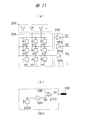
- control flow in the fourth embodiment is the same as that described in FIG. FIG. 22 shows operation waveforms when operating according to the control flow described in FIG.
- time T 1300 is the start time of step S1300 in FIG. 13
- time T 1302 is the start time of step S1302
- time T 1303 is The start time of step S1303, time T 1305 corresponds to the start time of step S1305.
- 22A shows changes with time of the reagent injected into the flow cell 103
- FIG. 22B shows changes with time in the heater wiring drive voltages V HE and V Ho.
- FIG. 22 (c) shows the temperature change of the solution.
- 22D shows the time change of the output voltage V D1 from the cell array 206 and the output voltage V DR from the reference circuit 1901.
- FIG. 22E shows the output voltage of the difference circuit 1902. It shows the time variation of the V 01.
- the cleaning solution, reagent dNTP, and ISFET chip 119 are cooled to a temperature T COLD at which the DNA polymerase is not activated.
- T 1302 After starting the injection of the reagent dNTP, drives the heater wire in the driving voltage at the time T 1303 to the cleaning liquid and the reagent dNTP in the flow cell 103 is replaced, the temperature of each well 121 of the chip surface DNA polymerase To the optimum temperature T HOT .
- the heater wiring has the configuration shown in FIG. 10A.
- the even-numbered wiring counted from the end of the chip has an even-numbered wiring at a driving voltage VHE
- the odd-numbered wiring has a driving voltage HHO having a phase opposite to that of VHE . Drive and reduce coupling noise.
- the cell 502 where the extension reaction has occurred When heating is started, the cell 502 where the extension reaction has occurred outputs a signal V D1 in which the background and the extension signal V SIG are superimposed, while the reference circuit 1901 outputs a signal V DR including only the background. Is done.
- the difference circuit 1902 obtains a difference between the signal V D1 and the signal V DR, and the difference circuit 1902 outputs a high-quality decompressed signal V SIG that does not include background as the final output voltage V O1. .
- the output voltages V D1 and V DR also change during the reagent injection (between T 1302 and T 1303 in the figure), which is due to the difference in the ionic composition of the cleaning liquid and the reagent dNTP.
- FIGS. A configuration example of the reference cell 1901 included in the reference circuit is shown in FIGS.
- a well having an opening size (length in the X-axis direction or Y-axis direction in plan view) ⁇ 2 smaller than the diameter ⁇ 1 of the bead 122 with DNA is prepared as a reference well (2401 in FIG. 24).
- the bead 122 since the bead 122 does not enter the well, the bead 122 does not contact the sensitive film 111 of the ISFET 109, and in principle, no extension reaction occurs in the well 121, and only the background is measured. Is possible.
- a well whose opening size (length in the X-axis direction and Y-axis direction in plan view) ⁇ 3 is sufficiently larger than the diameter ⁇ 1 of the bead 122 with DNA is prepared as a reference well (2402 in FIG. 24).
- the bead 122 is pressed against the bottom surface of the well by the centrifuge, and the bead 122 contacts the sensitive membrane 111 of the ISFET 109, but the bead 122 is not fixed to the well 121. . For this reason, the beads are washed away from the well 121 and lost by the washing solution flowed at the time of initialization. Since the beads are lost, the dNTP extension reaction does not occur in the subsequent steps even in such wells.
- the reference cell includes a reference well and an ISFET provided below the reference well, like the measurement cell, and is similar to the measurement cell. It has a circuit configuration ((a) of FIG. 6).
- FIG. 20 is a circuit diagram of an ISFET chip 119 using such a reference cell.
- a reference circuit 1901 and a difference circuit 1902 are added to the circuit shown in FIG.
- the reference circuit 1901 has the reference cell 2000 and the unit readout circuit 503 described above.
- the reference cell 2000 is not particularly limited, the row selection line is always selected.
- the reference signal DR is always output from the unit readout circuit 503 in the reference circuit 901.
- the difference circuit 1902 has a plurality of unit difference circuits 1902-1 that receive the output of each unit readout circuit 503 in the readout circuit 209 and the reference signal DR.
- the unit difference circuit 1902-1 calculates the difference between the reference signal DR and the output from the unit readout circuit 503 in the readout circuit 209, and outputs the outputs O1 to O3.
- FIG. 25 shows another realization method.
- FIG. 25A is a schematic cross-sectional view of a reference cell array 2500 provided in the reference circuit 1901.
- FIG. 25B is a circuit diagram of a reference cell array 2500 provided in the reference circuit 1901.
- the reference cell array 2500 has a plurality of cells 2500-1 arranged in a matrix.
- the reference cell array 2500 is arranged in each column of the matrix, a plurality of row selection lines 2500-3 connected to the cells arranged in the column, and cells arranged in each row of the matrix.
- Each of the plurality of cells 2500-1 has a configuration similar to that of the cell 121 in the cell array 206.
- the reference cell array 2500 is loaded with beads by flowing a solution containing beads with DNA and beads without DNA at a constant rate in the initialization step. By doing so, as shown in FIG. 25 (a), the reference cell array 2500 has a well 2501 in which beads 122 with DNA are stochastically contained and a well 2502 in which beads 122 without DNA are contained. There is an empty well 2503 that does not contain the beads 122.
- each cell 2500-1 (ISFET) of the reference cell array 2500 is selected, and the signal of each cell 2500-1 is measured.
- a well containing a bead 122 without DNA is detected, and this is selected by a row selection circuit 2505 and a column selection circuit 2504 and used as a reference cell. That is, the output of the cell 2500-1 selected as the reference cell is used as a signal V DR.
- the difference between the measurement cell and the reference well is only the presence or absence of DNA, the background closer to the background of the measurement cell can be measured with the reference cell, and the extension signal can be extracted with higher accuracy.
- 2505-1 is a circuit for driving a row selection line
- 2506-1 is a unit readout circuit.
- FIG. 21 is a circuit diagram showing a circuit configuration of the cell array 206 and the reference circuit 1901.
- FIG. 21A shows a circuit configuration of the cell array 206, the selection circuit 205, and the readout circuit 209.
- the signals O1 to O3 output from the readout circuit 209 are signals with reduced background.
- the reference circuit 1901 includes a reference cell 2000 and a unit readout circuit 503 as in FIG. Further, the reference circuit 1901 includes a differential amplifier circuit (differential amplifier) 2102 that amplifies the difference between the reference signal DR from the unit readout circuit 503 and the reference voltage VRR. VR is applied to the reference electrode 100 as a reference voltage VREF.
- FIG. 21 shows the time variation of the voltage V R applied from the reference circuit 1901 to the reference electrode 100.
- the signal V D1 in which the background and the extension signal V SIG are superimposed is output from the cell 121 in which the extension reaction has occurred.
- a reference voltage VRR the voltage V R minus the signal V DR including only background measured in the reference cell 2000 is output.
- the reference voltage VREF of the reference electrode 100 is controlled by the controller 212. Therefore, the voltage V R from the reference circuit 1901 is supplied to the controller 212, according to the voltage V R from the reference circuit 1901, may be as to control the reference voltage VREF controller 212 is applied to the reference electrode 100. Further, the reference cell 2000 may be provided in the cell array 206. In this case, the controller 212 controls the reference voltage VREF applied to the reference electrode 100 so as to suppress the change (background) in the measurement value of the reference cell 2000.
Abstract
生体分子計測装置は、生体分子試料と化学反応してイオンを生成させる試薬を送出する送液装置203と、マトリクス状に配置され、イオンの濃度を測定する複数の半導体センサを有するセルアレイ206と、複数の半導体センサのそれぞれの上に設けられ、送液装置203から注入される生体分子試料を含む溶液で満たされた複数のウェルの温度を調節する温調機構207とを具備する。生体分子計測装置は、送液装置203と温調機構207を制御するコントローラ212を、更に具備し、コントローラ212は、ウェル内の溶液に供給される熱量とウェル内の溶液から発散される熱量との間の差が、複数のウェルのそれぞれにおいて等しくなるように、温調機構207を制御する。
Description
本発明は、生体分子計測装置に関し、特に半導体技術を用いた生体分子計測装置に関する。
近年、半導体技術を用いた大規模並列型の生体分子計測装置が注目されている。特許文献1から6には、反応槽(ウェル)内に注入された測定対象の試料と、測定対象の試料と特異的に反応する化学物質との相互作用を、ウェル付近に配置された半導体センサで検出するバイオセンサシステムが記載されている。半導体の微細加工技術によって数百万から10億を超える半導体センサを半導体チップ上に集積することができ、各半導体センサを並列動作させて測定できるため、測定のスループットを向上しやすい特徴がある。バイオセンサシステムの測定対象は幅広く、半導体センサに使用するデバイスを変えることにより、デオキシリボ核酸(DNA)の伸長反応や、グルコースと酵素の反応、抗原抗体反応、生きた細胞の生理化学的活動の測定などに利用可能である。特許文献1から6には、これらの反応の生成物を電気化学的または光学的に検出する方法が開示されている。
Ishido,et al.,Microbial Cell Factories. 2011
Bergveld, IEEE Sensors Conf., Oct., 2003
Good, et al., Biochemistry, Feb., 1966
本願の発明者が、生体分子計測の技術について検討したところ、特に次の3項目が重要であるとの認識を得た。
<温度制御>
生体分子計測においては、反応系の温度管理が重要である。例えば、前述のDNAの伸長反応は、DNAポリメラーゼと呼ばれる伸長酵素を作用させて測定する。DNAポリメラーゼは温度によってその活性度が変化する。こうした温度依存性は酵素の種類によって変わるが、例えば非特許文献1に記載されているDanio rerio pol βは30℃付近に活性のピークをもち、温度が1℃変わると活性度が10%程度変化する。そのため、反応を効率よく起こすには、DNAポリメラーゼの活性が高くなる温度範囲に反応系を維持する必要がある。
生体分子計測においては、反応系の温度管理が重要である。例えば、前述のDNAの伸長反応は、DNAポリメラーゼと呼ばれる伸長酵素を作用させて測定する。DNAポリメラーゼは温度によってその活性度が変化する。こうした温度依存性は酵素の種類によって変わるが、例えば非特許文献1に記載されているDanio rerio pol βは30℃付近に活性のピークをもち、温度が1℃変わると活性度が10%程度変化する。そのため、反応を効率よく起こすには、DNAポリメラーゼの活性が高くなる温度範囲に反応系を維持する必要がある。
また、測定の途中で温度が変化すると活性度が変化して反応生成物の量に差が出るため、より正確に生体分子を測定する上では、測定中は反応系の温度を適切な温度に維持することが望ましい。同様に、細胞を生きたまま測定するためには、細胞が死なず、かつ、目的とする生理化学的活動が生じるような温度範囲に反応系を管理することが重要である。
以上の点から、特許文献1から5には、温度調整機構を備えたバイオセンサシステムが記載されている。また、特許文献5には半導体チップ上のポリシリコン抵抗に電流を流し、ジュール熱によって半導体チップ上の反応槽(ウェル)を加熱する手法が記載されている。
<温度の均一性>
複数のウェルで同時並列的に測定を行う場合は、それぞれのウェルにおいて試料を同じ温度範囲に置くことが望ましい。すなわち、特許文献5に記載されているように、ウェルアレイ上の温度勾配をなるべく小さくし、各場所の温度を均一に保つことが重要である。これは、反応条件を各ウェルで同一に保ち、各ウェルで測定される信号のばらつきを減らし、測定の精度を上げる上で重要な事項である。
複数のウェルで同時並列的に測定を行う場合は、それぞれのウェルにおいて試料を同じ温度範囲に置くことが望ましい。すなわち、特許文献5に記載されているように、ウェルアレイ上の温度勾配をなるべく小さくし、各場所の温度を均一に保つことが重要である。これは、反応条件を各ウェルで同一に保ち、各ウェルで測定される信号のばらつきを減らし、測定の精度を上げる上で重要な事項である。
<温度変更時の低ノイズ化>
測定対象の生体分子によっては、積極的にウェルの温度を変えながら測定する場合がある。例えば、特許文献5には、55℃から95℃の範囲で繰り返し反応系の温度を変えながらポリメラーゼ連鎖反応(PCR)を進め、その際のpH変動をイオン感応性電界効果トランジスタ(Ion Sensitive Field Effect Transistor:以下、ISFETと称する)で検出する測定について記載されている。
測定対象の生体分子によっては、積極的にウェルの温度を変えながら測定する場合がある。例えば、特許文献5には、55℃から95℃の範囲で繰り返し反応系の温度を変えながらポリメラーゼ連鎖反応(PCR)を進め、その際のpH変動をイオン感応性電界効果トランジスタ(Ion Sensitive Field Effect Transistor:以下、ISFETと称する)で検出する測定について記載されている。
この様に温度を変更する場合、温度変更に起因するノイズを抑える必要がある。ここで言うノイズとは、2種類のノイズを意味している。すなわち、1つ目のノイズとは、温度変化に起因して溶液の物性、例えばpHが変化し(非特許文献3)、それが信号として出力されてしまうことを言う。特許文献3には、温度基準センサによってノイズを記録し、信号処理によってノイズを減算することが記載されている。2つ目のノイズは、温度を変更するために、ヒータをオン/オフする駆動動作により、ヒータと半導体センサの電極との間に存在する寄生的な容量性結合を介してセンサ電極に伝達されるカップリングノイズである。
<重要3項目と先行技術文献との関係>
特許文献1、3、および4に記載された温度調整機構は、ウェルを反応に最適な温度にするためのものである。しかしながら、これらの特許文献には、複数のウェルにより構成されるところのウェルアレイ上の温度分布を均一化する具体的な手段については示されていない。
特許文献1、3、および4に記載された温度調整機構は、ウェルを反応に最適な温度にするためのものである。しかしながら、これらの特許文献には、複数のウェルにより構成されるところのウェルアレイ上の温度分布を均一化する具体的な手段については示されていない。
また、特許文献5には、ウェルアレイ上の温度分布を均一化することの重要性が述べられているが、具体的な実現方法については何ら記述がない。
特許文献2には、センサごとに温度センサとヒータを設ける構成について記載がある。しなしながら、多数のセンサを集積化する大規模並列型の生体分子計測装置においては、センサごとに温度センサとヒータとを設けるとセンサ面積が増大し、半導体チップが高コスト化すると言う課題が生じる。
一方、温度変更時のノイズに関しては、特許文献3に対策技術が示されている。しかしながら、特許文献3に示されている対策技術では、温度基準センサは、ウェルアレイ上の温度分布に応じてチップ上に複数設ける必要があり、半導体チップの面積の増大を招くと言う問題が生じる可能性がある。また、ヒータを駆動する際に生じるカップリングノイズについては、いずれの先行技術文献においても何ら検討されていない。
本発明は、上記のような課題に鑑みてなされたものであり、半導体センサを用いて生体分子試料を測定する際、より高精度な測定が可能な生体分子計測装置を提供することを目的とする。
本発明の前記ならびにそのほかの目的と新規な特徴は、本明細書の記述および添付図面から明らかになるであろう。
本願において開示される発明のうち、代表的なものの概要を簡単に説明すれば、次のとおりである。
すなわち、生体分子計測装置は、生体分子試料と化学反応してイオンを生成させる試薬を送出する送液装置と、マトリクス状に配置され、イオンの濃度を測定する複数の半導体センサと、複数の半導体センサのそれぞれの上に設けられ、送液装置から注入される生体分子試料を含む溶液で満たされた複数のウェルと、複数のウェルの温度を調節する温度調整機構とを具備する。生体分子計測装置は、上記した送液装置と上記した温度調整機構を制御するコントローラを有しており、該コントローラは、ウェル内の溶液に供給される熱量とウェル内の溶液から発散される熱量との間の差が、複数のウェルのそれぞれにおいて等しくなるように、温度調整機構を制御する。複数のウェルにおいて、それぞれのウェルに供給される熱量と発散される熱量との間の差が等しくなる様に制御されるため、高精度な測定が可能となる。
また、一実施の形態においては、生体分子計測装置は、生体分子試料と化学反応してイオンを生成させる試薬を送出する送液装置と、マトリクス状に配置され、イオンの濃度を測定する複数の半導体センサと、複数の半導体センサのそれぞれの上に設けられ、送液装置から注入される生体分子試料を含む溶液で満たされた複数のウェルと、複数のウェルにおける溶液の熱を発散させる放熱体とを具備する。ここで、放熱体は、ウェル内の溶液に供給される熱量と、ウェル内の溶液から発散される熱量との差が、複数のウェルのそれぞれにおいて等しくなる様な構造を有している。この一実施の形態においては、放熱体の熱伝導率が異なる様にされ、それぞれのウェルに供給される熱量と発散される熱量との間の差が等しくなる様にされる。そのため、高精度の測定が可能となる。また、放熱体の熱伝導率を変えることにより、供給される熱量と発散される熱量との間の差が等しくなる様にされるため、生体分子計測装置の制御を簡略化することが可能となる。
本願において開示される発明のうち、代表的なものによって得られる効果を簡単に説明すれば、以下のとおりである。
より高精度な測定が可能な生体分子計測装置を提供することができる。
以下、本発明の実施の形態を図面に基づいて詳細に説明する。なお、実施の形態を説明するための全図において、同一部分には原則として同一の符号を付し、その繰り返しの説明は、原則として省略する。
以下の実施の形態においては便宜上その必要があるときは、複数のセクションまたは実施の形態に分割して説明するが、特に明示した場合を除き、それらはお互いに無関係なものではなく、一方は他方の一部または全部の変形例、詳細、補足説明等の関係にある。また、以下の実施の形態において、要素の数等(個数、数値、量、範囲等を含む)に言及する場合、特に明示した場合および原理的に明らかに特定の数に限定される場合等を除き、その特定の数に限定されるものではなく、特定の数以上でも以下でも良い。また、以下の実施の形態において、その構成要素(要素ステップ等も含む)は、特に明示した場合および原理的に明らかに必須であると考えられる場合等を除き、必ずしも必須のものではないことはいうまでもない。
同様に、以下の実施の形態において、構成要素等の形状、位置関係等に言及するときは、特に明示した場合および原理的に明らかにそうでないと考えられる場合等を除き、実質的にその形状等に近似または類似するもの等を含むものとする。このことは、上記数値および範囲についても同様である。
以下、半導体センサとしてISFETを用い、生体分子計測装置としてDNAの配列を決定するDNAシーケンサを例として、説明する。しかしながら、本発明の適用は、DNAシーケンサに限定されるものではなく、生体分子の反応生成物をアレイ状のセンサで電気化学的、光学的に計測するシステムに広く適用することができる。また、ISFETはイオン感応膜を適切に選択することによって種々のイオンを検出することができるので、例えばナトリウムイオンやカリウムイオンが変化するような生体分子を測定する装置に対しても、本発明を適用することができる。
また、生体分子の反応生成物により蛍光標識を発光させ、その光を半導体光センサ、例えばフォトダイオードで光学的に計測するシステムについても本発明は適用可能である。また、そのほかの原理として、微細な穴(ナノポア)に測定対象の生体分子を通し、その時の封鎖電流、またはナノポアの近傍に設けられたセンサで、ナノポア中にある生体分子の種類を同定するナノポア型生体分子計測装置についても適用可能である。
(実施の形態1)
図1の(a)および(b)は、後で図2を用いて述べるセルアレイ206と、その上部のフローセル103の構成を示す図である。ここで、図1の(b)は、セルアレイ206の平面図である。また、図1の(a)は、セルアレイ206の3個のISFET109と反応槽(以下、ウェルと称する)106~108の断面図であり、図1の(b)のA-A’線断面図に相当する。なお、各ISFET109への配線は省略してある。また、図1の(a)において、符号109は、同図において左側に設けられたISFETに対してのみ付されており、他の2個のISFETについては、符号109の明示は省略されている。また、図1の(b)においては、ウェルに対して符号121が付されており、図1の(a)においては、個別にウェルを示すために、ウェルに対して符号106~108が付されている。以後、総称してウェルを示す場合は、符号121をウェルに対して付し、個別にウェルを示す場合は、個別の符号をウェルに付す。
図1の(a)および(b)は、後で図2を用いて述べるセルアレイ206と、その上部のフローセル103の構成を示す図である。ここで、図1の(b)は、セルアレイ206の平面図である。また、図1の(a)は、セルアレイ206の3個のISFET109と反応槽(以下、ウェルと称する)106~108の断面図であり、図1の(b)のA-A’線断面図に相当する。なお、各ISFET109への配線は省略してある。また、図1の(a)において、符号109は、同図において左側に設けられたISFETに対してのみ付されており、他の2個のISFETについては、符号109の明示は省略されている。また、図1の(b)においては、ウェルに対して符号121が付されており、図1の(a)においては、個別にウェルを示すために、ウェルに対して符号106~108が付されている。以後、総称してウェルを示す場合は、符号121をウェルに対して付し、個別にウェルを示す場合は、個別の符号をウェルに付す。
図1の(b)に示す様に、セルアレイ206は、2次元的にマトリクス状に配置された複数のウェル121を有し、各ウェル121の底部にはISFET109のイオン感応膜111(図1の(a))が配置されている。ウェル121は、半導体プロセスによって形成された1辺数100nm~数μm程度の大きさの穴である。測定時には、各ウェル121の中に、測定対象となる生体分子105が付着したビーズ122が装填される。図1の(b)に示されたセルアレイ206においては、9個のウェル121が、3行、3列のマトリクス状に配置され、9個のウェル121の内、6個のウェル121にビーズ122が装填された状態が示されている。
生体分子105がDNAである場合は、DNAをビーズ122に付着させる際に、エマルジョンPCRなどの方法によって測定対象のDNAを複製し、ビーズ122上のDNA本数を増やしておくと、発生する水素イオン(反応の詳細は図3で後述する)の量が増えて検出が容易になる。フローセル103は、生体分子の品質保持に必要な緩衝液(バッファ)や、生体反応に必要な試薬を含む溶液104で満たされる。後述するように、測定中に試薬の交換が必要な場合は、フローセル103に溶液の注入口101と排出口102が設けられる。
ISFET109は、イオン感応膜111、保護膜112、フローティング電極113、ゲート電極114、ゲート酸化膜115、ドレイン領域116、ソース領域117、シリコン基板123、基板コンタクト領域110を有する。フローティング電極113とゲート電極114がなく、ゲート酸化膜115の上に保護膜112とイオン感応膜111を直接積層する場合もある。ISFETとその直上に形成された1つのウェルをまとめてセル118と呼ぶ場合もある。なお、図1の(a)においては、基板コンタクト領域110とシリコン基板123は、3個のISFETに対して、共通となっている。
生体分子105から発生するイオンを測定する際は、感応膜111を溶液104に接触させ、参照電極100を試薬溶液104中に浸す。この状態で、参照電極100に電圧VREFを与えると、溶液中のイオン濃度に応じてイオン感応膜111上で電位差が生じ、ISFET109の閾値電圧がシフトしたように見える。ISFET109の閾値電圧の変動をモニタすることで、ウェル121中での生体反応に起因する生成物イオンの濃度変化を測定できる。ISFET109を水素イオン濃度センサ、すなわちpHセンサとして用いる場合、水素イオン濃度の変動による理論上の電圧変動は、ネルンストの式から求めることができ、25℃においてはおおよそ59mV/pHである。実際のISFETにおいては、これより若干低下し、pHあたり数10mV程度である。なお、図1の(a)および(b)において、120は、後で説明するが、ヒータとして用いられる金属配線である。
図2は、実施の形態1に係る生体分子計測装置の機能ブロック図である。測定対象である生体分子105(図1の(a))は、ビーズ122(図1の(a))に付着してセルアレイ206上のウェル121(図1の(b))に装填される。生体分子105が反応するために必要な溶液は、送液装置203によって試薬容器201から送出され、ISFETアレイチップ119上で生体分子105と反応する。ISFETチップ119は、この反応によって生成されるイオンの濃度変化を検出する。反応後の廃液は、排出口102(図1(a))から排出され、廃液容器210によって回収される。
この実施の形態においては、試薬容器201として、3個の試薬容器が設けられており、それぞれの試薬容器に試薬1から試薬3が充填されている。また、送液装置203は、洗浄のために、洗浄容器216から洗浄液を、フローセル103(図1(a))へ送出する。送液装置203は、例えば一般的な送液ポンプを複数使用して実現することができる。または、窒素やアルゴンなどの不活性ガスを、容器ごと(3個の試薬容器201のそれぞれと洗浄容器216と)に用意されたバルブを介して圧力を調整しながら試薬容器201および洗浄容器216に注入して、ガスの圧力により試薬容器201あるいは洗浄容器216から試薬あるいは洗浄液を押し出すことによって実現することもできる。
コントローラ212は、あらかじめプログラムされた実験シーケンスとデータ処理装置211が取得したデータに応じて、送液装置203の送液ポンプの送液タイミングと送液量の調整、ISFETチップ119の動作状態の制御、データ処理装置211の制御、流路202、213、214のいずれかまたはISFETチップ119上のフローセル103に設けられた参照電極100の電圧制御などを実施する。さらにコントローラ212は、ISFETチップ119上に設けられた温度センサ215の出力に基づき温度調整機構(以下、温調機構とも称する)207と試薬溶液および洗浄液の温度を調整する温調機構200を制御する。
データ処理装置211は、ISFETチップ119から出力された測定結果を示すデータを取得して解析する。データ処理装置211は、一般的なA/D変換器を搭載したインターフェースボードとコンピュータによって構成することができる。
ISFETチップ119は、半導体プロセスにより、1個の半導体チップに形成され、セルアレイ206、温度センサ215、温調機構207、選択回路205および読出回路209を有している。選択回路205および読出回路209については後述する。
なお、図2において、細い矢印は電気信号の流れを示し、波線が付された太い矢印は、試薬・洗浄液・廃液の流れを示している。
図3の(a)から(c)は、DNAの構造と伸長反応を説明する図である。図3の(a)は、1本鎖DNAを模式的に表した図である。実際の1本鎖DNAは、リン酸とデオキシリボースからなる鎖に4種類の塩基が結合し、複雑な立体構造を形成する。ここでは簡単化のために、リン酸とデオキシリボースからなる鎖を直線304で表し、4種類の塩基、すなわちアデニンをA(300)、チミンをT(301)、シトシンをC(302)、グアニンをG(303)のように記号で表す。
図3の(b)は、DNAの伸長反応を模式的に表した図である。ATCGの1本鎖DNA305に、TAGからなるプライマ306が結合した状態を示す。この状態で、シトシンを含むデオキシリボヌクレオチド3リン酸(dNTP)の一種(dCTP)307と、図中では示していない伸長酵素であるDNAポリメラーゼが存在すると、dCTPがG末端に結合すると同時に、図3の(c)に示す様に、2リン酸309と水素イオン308が離脱する。
水素イオン308を検出することによりDNA配列を決定する方法は、以下の通りである。まず、配列を決定したい未知の1本鎖DNA305にプライマ306を結合させる。この状態で、dCTP、dTTP、dATP、dGTPの4種の試薬を順番に注入し、それぞれの試薬を注入した際の水素イオン濃度を測定する。例えばdATPを注入した時に水素イオン濃度が上昇すれば、元の1本鎖DNA305のうちプライマ306が結合した部分を除いた先頭が、Aの相補塩基、すなわちTであったことが分かる。上記試薬注入と水素イオン濃度測定を繰り返すことにより、順番にDNA配列を決定することができる。
図4は、実施の形態1に係る生体分子計測装置がDNA配列を決定する処理を説明するフローチャート図である。以下、図4の各ステップについて説明する。
先ず、初期化のステップS400において、ビーズ122をウェル121に装填し、装填を終えた後、ISFETチップ119を生体分子計測装置にセットする。また、ステップS400において、反応に用いる試薬dNTPおよび洗浄液などの各種溶液は、あらかじめ温調機構200を用いて、DNAポリメラーゼの至適温度付近に温度を調整しておく。測定を開始すると、コントローラ212はまず、送液装置203を使って注入口101を介して洗浄液をISFETチップ119に注入し、フローセル103全体を洗浄液で満たす。この時、後述する温調機構207により、ISFETチップ119上の各ウェル121内の溶液温度が、先のDNAポリメラーゼの至適温度付近になるように温度調整がなされる。
なお、ビーズ122をウェル121に装填する際には、ビーズ122を含む溶液をISFETチップ119に塗布した後、例えば遠心分離器により、ISFETチップ119を回転させる。これにより、ビーズ122は、ウェル121に挿入され、ウェル121の底面に押し付けられて、ウェル121に固定される。このとき、セルアレイ206の全てのウェル121にビーズ122が挿入され、固定されるとは限らず、例えば図1の(b)に示した様に、ビーズ122が装填されたウェル121とビーズ122が装填されていないウェル121とが発生する。
次に、ステップS401において、あらかじめ決められた手順で試薬dNTPが選択される(図では、例としてdNTP=dATPが示されている)。送液装置203は、選択された試薬を試薬dNTPとして、注入口101を介してフローセル103へ注入する。このとき、先に注入されていた洗浄液は、試薬dNTPの注入により、排出口102から押し出され、洗浄液と試薬dNTPとの入れ替えが行われる(ステップS402のdNTP注入)。
このように、同じ温度に調整された溶液どうし(すなわち洗浄液と試薬dNTPの溶液)を、同じ温度に調整されたウェル121内に注入することで、洗浄液と試薬との交換(あるいは特定の試薬から別の試薬への交換)に伴うウェル121内の温度変化を最小限にとどめることが可能となる。また、ISFETチップ119上の各ウェル121での反応温度条件を、各ウェル121間でなるべく近くすることが可能となる。その結果、温度変化に起因するノイズ、具体的には溶液自体のpH変動などを最低限に抑えることが可能となる。
ステップS403(伸長信号測定)においては、各ウェル121に設けられているISFET109によって、対応するウェル内のpH変化が測定される。フローセル103の下流、すなわち排出口102近辺にも試薬dNTPが行き渡り、伸長反応が十分に起こる時間を経過し、さらに必要な期間だけ信号を測定した段階で、コントローラ212は、送液装置203に対して洗浄液の注入を開始させる。これにより、送液装置203は、フローセル103の上流に設置してある注入口101から、フローセル103へ洗浄液の注入を開始し、反応しなかった試薬dNTPと、反応生成物である水素イオンおよび2リン酸を、排出口102から排出させ、洗い流す(ステップS404の洗浄液注入)。
コントローラ212は、洗浄が終わった後、次の試薬dNTPを、ステップS405~S409で選択し、以後、DNA配列が決定するまで、ステップS402に戻って、同様な処理を繰り返す。すなわち、DNA配列が決定するまで、選択された試薬dNTPがステップS402で注入され、測定が行われる。この繰り返しの過程において、ISFET109が測定した信号は、データ処理装置211が備えるA/D変換器(図示せず)によって、デジタル信号に変換され、データ処理装置211が備える記憶装置(図示せず)内に測定データとして蓄積される。データ処理装置211は、この繰り返しの処理によって、蓄積された測定データに基づいて、配列を判定し、DNAの構造を特定する。
なお、試薬の選択のステップは、一例を述べると、ステップS405において、試薬dNTPがdATPであったと判定された場合、次にステップS406が実行され、ステップS405において、試薬dNTPがdGTPであったと判定された場合、次にステップS407が実行される。ステップS406が実行されると、次の試薬dNTPとしてdGTPが選択され、ステップS407が実行されると、次の試薬dNTPとしてdCTPが選択される。
図5は、ISFETチップ119を構成する機能ブロックのうち、セルアレイ206、選択回路205、読出回路209の構成例を示す回路図である。
セルアレイ206は、複数のセル502と、複数本(2のn乗本)の行選択線500と、複数組のデータ線組501とを有している。複数本の行選択線500と複数組のデータ線組501は、2次元的に格子状に配置され、セル502は、行選択線500とデータ線組501との交点に配置される。すなわち、セル502は、2次元的に、マトリクス状に配置され、マトリクスの各行にデータ線組501が配置され、マトリクスの各列に行選択線500が配置されている。マトリクス配置されたセル502のそれぞれは、対応する行および列に配置されたデータ線組501および行選択線500に接続される。
選択回路205は、nビットデコーダ(図示せず)と複数のドライバ504とによって構成され、コントローラ212から与えられたn本の行アドレスに基づき、2のn乗本の行選択線500のうち1つを活性化する。セル502の回路構成の一例を後で図6を用いて説明するが、セル502は、ISFET109と、ISFET109を選択するための選択トランジスタ600、601とを有している。複数の行選択線500の内の1つの行選択線が活性化されることにより、その活性化された行選択線500に接続されている複数のセル502が選択され、選択された複数のセル502の出力は、対応するデータ線組501を介して、読出回路209に供給される。読出回路209は、各データ線組501に接続された複数の単位読出回路503を有しており、選択された複数のセル502の出力は、データ線組501を介して対応する単位読出回路503に供給され、アナログのデータD1~Dnとして出力される。
図6の(a)は、セル502の構成例を示す回路図であり、図6の(b)は単位読出回路503の構成例を示す回路図である。セルアレイ206としてマトリクス状に配置されたセル502のそれぞれは、互いに同じ構成にされている。そのため、図6の(a)には、1個のセル502の回路構成のみが示されている。同様に、読出回路209を構成する複数の単位読出回路503も、互いに同じ回路構成にされているため、図6の(b)には、1個の単位読出回路503の回路構成のみが示されている。
セル502は、図6の(a)に示されている様に、イオン感応膜111を有するISFET109、選択トランジスタ600、601を有している。また、この実施の形態1において、複数のデータ線組501のそれぞれは、ソース線SLk(602)、データ線DLAk(603)、DLBk(604)の3本から構成されている。ISFET109は、1対の電極(ソース領域とドレイン領域)を有している。ISFET109の一方の電極は、データ線DLBkに接続され、他方の電極は選択トランジスタ600および601を介してデータ線DLAkおよびソース線SLkに接続されている。また、選択トランジスタ600および601のそれぞれのゲートは、行選択線WLj(500)に接続されている。ここで、kはデータ線組501の番号を示しており、jは、行選択線500の番号を示している。
行アドレスによってj番目の行選択線WLjが指定され、その行選択線WLjがハイ状態に活性化されると、この行選択線WLjに接続されている全てのセル502において、選択トランジスタ600、601が導通状態となる。これにより、同一の行選択線WLjに接続された全てのセル502のISFET109の他方の電極が、それぞれ対応するソース線SLkとデータ線DLAkに接続される。読出回路209は、例えばISFET109の閾値変化を電圧として出力する広く知られた回路で実現可能である。この読出回路209を構成する複数の単位読出回路503の具体的な回路例は、図6の(b)に示すとおりである。単位読出回路503は、2つの一般的な定電流源605と609、2つのアンプ606と607、および出力用のアンプ608とトランジスタ610とを有している。なお、図6の(b)では、省略されているが、定電流源605および609は、コントローラ212(図2)に結合されており、それぞれの電流値が、コントローラ212よって設定される。
セル502および単位読出回路503の詳細な動作については割愛するが、行選択線で選択されたISFETの閾値の変化が、出力端子Dkの電圧変化、すなわちデータ線DLAkの電圧変化として出力される。概略を述べると、データ線DLBkを介してアンプ607から電圧がISFET109の一方の電極に与えられ、定電流源605によりソース線SLkからISFET109に電流が供給される。ISFET109の閾値電圧変化は、電流が流れることにより生じる電圧変化として、導通状態にされている選択トランジスタ601を介してデータ線DLAkに表れる。この電圧変化がアンプ606および出力用のアンプ608を介し、データとして、出力端子Dk(データ線DLAk))に出力される。なお、図6の(a)および(b)においては、全てのトランジスタ109、600、601および610は、Nチャンネル型MOSFET(以下、NMOSと称する)である。しかしながら、もちろん全てのトランジスタをPチャンネル型MOSFET(以下、PMOSと称する)で構成してもよい。PMOSで構成した場合、行選択線WLjの論理は反転する。
図5に示す回路においては、複数のISFET109のいずれかを選択回路205によって選択し、その出力を読出回路209によって読み出すこととしている。しかしながら、ISFETチップ119のデータ出力ピンの本数が許す限りは、ISFET109毎に出力ピンを設けてもよい。また、図2に示した例では、ISFETチップ119の出力をアナログデータからデジタルデータへ変換するA/Dコンバータ(図示しない)は、データ処理装置211に設けられている。この様なA/Dコンバータは、ISFETチップ119上に搭載し、ISFET109の出力をデジタルデータに変換してから、出力する様にしてもよい。この場合、ISFETチップ119からデータ処理装置211までの通信経路がデジタル化されるため、経路上の干渉ノイズに対する耐性が向上する。
次に、温調機構207により、半導体チップ(ISFETチップ119)上の各ウェル121内の溶液温度を均一性良く調整する具体的な方法について説明する。まず、溶液の加熱は、図1に示したオンチップの金属配線120へ電流を流して、ジュール発熱を発生させることで行う。すなわち、半導体チップに形成された金属層の金属配線120へ電流を流すことにより、ウェル121に充填された溶液を加熱する。この様に、オンチップの金属配線120を用いることにより、各ウェル121と熱源との間の距離を近くすることができる。この様にすることにより、半導体チップとは別に、すなわちオフチップ、例えば半導体チップの下側にヒータ膜を入れる場合よりも迅速に各ウェル121内の溶液を加熱できる。また、後述のように配線の引き回しを工夫することで、より半導体チップ(ISFETチップ119)上の位置における温度差を低減できる。
チップ全域にわたって、同じ太さ(幅および厚み)の金属配線120(以下、ヒータ配線とも称する場合がある)を配置し、このヒータ配線を同じ電流で駆動した場合、チップ上に温度差が発生する恐れがある。これは、チップの外周は外部環境との接点が多く熱が逃げやすいのに比べ、チップの中心の方は熱が逃げにくいためである。すなわち、半導体チップの中心と外周(周辺)とでは、熱の発散量が異なり、中心に比べ外周の方が発散量が多くなる。
図7は、半導体チップの温度分布をシミュレーションにより求めた温度分布の図である。シミュレーションは、半導体チップに、ヒータ配線を設置し、ヒータ配線を電流駆動して、チップに均等に熱量を供給する様な条件で行った。図7において、700は半導体チップを示しており、701はチップの中心部分、702はチップの外周(周辺)部分を示している。中心部分701と外周部分702との間では、約5℃以上の温度差が発生している。
そこで実施の形態1においては、チップの外周寄りにヒータ配線120を配置し、チップの中心寄りにはヒータ配線120を配置しないこととした。具体的なヒータ配線の配置例を、図8および図9に示す。
図8の(a)は、ヒータ配線120が配置されたセルアレイ206の平面図である。同図において、121はウェルを示しており、セルアレイ206に、マトリクス状に配置されている。ヒータ配線120は、セルアレイ206の外周にリング状に、2本配置されている。同図の例では、ヒータ配線120は、セルアレイ206の外周(周辺)に配置されたヒータ配線120-1とヒータ配線120-1よりも中心寄り配置されたヒータ配線120-2とを含んでいる。リング状のヒータ配線120-1、120-2のそれぞれに対して、対角線上の給電点801-2、804-2から、給電点801-1、804-1へ向けて電流(実線矢印)が供給される。
入出力パッド800-2、803-2からヒータ配線120-1、120-2への給電点801-2、804-2までに至る配線802-2、805-2は、ヒータ配線120-1、120-2よりも低抵抗な配線を用いることが好ましい。同様に、給電点801-1、804-1から入出力パッド800-1、803-1までに至る配線802-1、805-1も、ヒータ配線120-1、120-2よりも低抵抗な配線を用いることが好ましい。これにより、配線802-1、805-1、802-2、805-2での発熱を、ヒータ配線120-1、120-2と比較して相対的に減らし、配線802-1、805-1、802-2、805-2での発熱に起因するチップ上の発熱の不均一性を軽減することができる。
図8の(a)においては、セルアレイ206の角部から、ヒータ配線に対して給電する例を示したが、セルアレイ206の角部ではなく、セルアレイ206の辺から、ヒータ配線に給電する様にしてもよい。
図8の(b)は、ヒータ配線120が配置されたセルアレイ206の他の平面図である。図8の(b)に示した実施の形態においては、L字やコの字型のヒータ配線120が用いられている。L字型やコの字型のヒータ配線120が、セルアレイ206の外周寄りに、多く集まる様に配置されている。なお、図8の(b)においても、ヒータ配線120を駆動する電流は実線の矢印によって示されている。また、ヒータ配線120へ電流を給電する給電点は、黒丸で示されている。
図8に示したヒータ配線120の配置に対して、図9には、更に別のヒータ配線の配置例が示されている。図9の(a)および(b)は、ヒータ配線120が配置されたセルアレイ206の他の平面図である。図9の(a)においては、一筆書きの要領でヒータ配線120が渦巻形状に配置されている。かかる構成によれば、入出力パッド900-1、900-2から給電点901-1、901-2に至るまでの配線の本数や長さ、入出力パッドの数を低減することが可能である。
また、図9の(b)には、一筆書きの要領でヒータ配線120を配置した他の配置例が、セルアレイ206の平面図として示されている。この場合においても、入出力パッド902、903から給電点に至るまでの配線の本数や長さ、入出力パッドの数を低減することが可能である。また、図9の(a)の配置においては、給電点901-2と入出力パッド900-2とを結ぶ配線904が、ヒータ配線120と交差するため、配線904として、ヒータ配線120とは別の配線層における金属配線を用いることが必要とされる。これに対して、図9の(b)に示した配置では、交差を減らすことが可能となり、チップに形成される配線層をより有効に活用することが可能となる。
なお、図9の(a)および(b)においても、ヒータ配線120を駆動する電流は、実線の矢印で示されており、給電点は黒丸で示されている。また、図8および図9において、入出力パッドは、給電だけに使われる場合、入出力ではなく、入力パッドあるいは出力パッドと見なすことができる。
ヒータ配線120へ給電する電流の値は、半導体チップ(ISFETチップ119)に設けられた温度センサ215の出力に基づきコントローラ212(図2)が決定する。あるいは、温調機構207(図2)内にヒータ制御回路(図示せず)を設け、温度センサ215の値に基づき、ヒータ制御回路が決定しても良い。温度センサ215としては、チップ上に半導体の温度センサを設ける様にしてもよいし、ヒータ配線120の抵抗を温度のモニタとして用いてもよい。金属配線の抵抗は温度に比例して増大する関係があるため、抵抗をモニタすることで特別に温度センサを追加することなくチップ上の温度を測定することが可能である。
<実施の形態1:変形例1>
以上の説明においては、ヒータ配線120の配置によって、半導体チップ上の温度を均一化する例を示した。しかしながら、温度を制御する手法はこれに限らない。例えば、セルアレイ206に配置されるヒータ配線120の太さ(幅)を、位置に応じて変更する様にしてもよい。図10の(a)および(b)は、セルアレイ206に配置される複数のヒータ配線120の一部の太さを変更した場合のセルアレイ206の平面図である。
以上の説明においては、ヒータ配線120の配置によって、半導体チップ上の温度を均一化する例を示した。しかしながら、温度を制御する手法はこれに限らない。例えば、セルアレイ206に配置されるヒータ配線120の太さ(幅)を、位置に応じて変更する様にしてもよい。図10の(a)および(b)は、セルアレイ206に配置される複数のヒータ配線120の一部の太さを変更した場合のセルアレイ206の平面図である。
図10の(a)には、セルアレイ206に配線される複数のヒータ配線206において、一部の太さ(幅)を太く(広くし)したヒータ配線を配置した例が示されている。図10の(a)に示した例においては、セルアレイ206に配置される複数のヒータ配線120のうち、セルアレイ206の中心領域に配置されるヒータ配線120-10の平面形状が、セルアレイ206の外周領域に配置されるヒータ配線120-1と異なる様にされている。すなわち、平面視において、ヒータ配線120-10は、セルアレイ206の中心領域に配置される部分が、太い形状を有し、セルアレイ206の外周領域に配置される部分が、中心領域に配置される部分に比べて細くされている。これに対して、ヒータ配線120-1は、ほぼ一定の太さを有する形状とされている。
すなわち、ヒータ配線120-10は、その延在方向(例えば、図面の下側から上側への方向)に沿って、途中の箇所(中心領域に配置される部分)が太くなる形状を有している。特に制限されないが、ヒータ配線120-10において、外周領域に配置される部分の太さ(幅)は、外周領域に配置されるヒータ配線120-1の太さと同じにされている。また、外周領域に配置されるヒータ配線120-1の太さは、その延在方向において一定とされている。
この様な形状を有するヒータ配線120-1および120-10のそれぞれには、同じ値の電流が、例えば実線の矢印方向に給電される。これにより、各ヒータ配線120-1および120-10を、同じ電流値I(アンペア)の電流で駆動しても、セルアレイ206の中心領域での加熱量と外周領域での加熱量とを変えることができる。すなわち、ヒータ配線による発熱量P(ジュール)は、その配線の抵抗をR(オーム)、加熱時間をt(秒)とすると、P=I2*R*tで表わされる。連続した配線上では電流Iは一定である。一方、配線を太くした箇所は、細い箇所よりも断面積が増えて単位長さ当たりの抵抗Rが減少するため、発熱量が減少する。従って、図10の(a)の構成によれば、チップ中心へ供給される熱量をチップ外周より少なくすることができる。
一方、セルアレイ206に配置される各ヒータ配線120を電圧Vで駆動する場合は、図10の(b)のように中心部の配線太さを細くすればよい。すなわち、その延在方向において、中心領域に配置される箇所が、外周領域に配置される箇所に比べて、その太さ(幅)が細くされたヒータ配線120-11が、セルアレイ206の中心領域に配置される。この場合も、セルアレイ206の外周領域に配置されるヒータ配線120の太さは、その延在方向に対して一定とされている。また、ヒータ配線120の太さは、ヒータ配線120-11の外周領域に配置される箇所における太さと同じにされる。この様にすることにより、セルアレイ206の中心領域に対して、ヒータ配線から供給される熱用を減らすことができる。すなわち、ヒータの発熱量はP=V2/R*tで表わされる。そのため、太さが細くなり、抵抗が高くなる箇所(ヒータ配線120-11における)で、ヒータ配線120-11における発熱量は、より太い外周側の箇所および配線よりも小さくなる。
駆動電流Iおよび駆動電圧Vは、前述の温度センサ215の出力値に基づき、コントローラ212が決定するか、もしくは、温調機構207内にヒータ制御回路(図示せず)を設け、温度センサ215の値に基づき、ヒータ制御回路が決定してもよい。
図11の(a)には、セルアレイ206に配置されるヒータ配線120を2つの金属配線層を使って構成し、さらに各金属配線層の配線の太さを変えることで温度の均一化を図った変形例が示されている。すなわち、図11の(a)において、中段部分は、2つの金属配線層により構成されたヒータ配線120を有するセルアレイ206の平面図を示している。セルアレイ206の平面図において、a-a’断面で見た断面図が、図11の(a)において、下段に示されている。また、図11の(a)において、上段および右側には、セルアレイ206に配置されたヒータ配線120の発熱量の位置に応じた変化が示されている。
なお、図11の(a)において、121は、マトリクス状に配置されたウェルを示しており、実線の矢印は、駆動電圧Vを示している。また、図11の(a)において、下段に示されたチップの断面を示す断面図には、図面を見やすくするために、ウェル121等は省略し、ヒータ配線となる2つの金属配線層のみが示されている。また、図11の(a)において、上段に示された発熱量と位置との関係を示す部分は、セルアレイ206の中心領域を通る位置の発熱量を示しており、横軸はセルアレイ206のX座標を示し、縦軸は発熱量を示している。更に、図11の(a)において、右側に示された発熱量と位置との関係を示す部分も、セルアレイ206の中心領域を通る位置の発熱量を示しており、縦軸はセルアレイ206のY座標を示し、横軸は発熱量を示している。
ヒータ配線120は、図11の(a)の下段に示した断面図に示す様に、Y方向に延在する上層の金属配線1102と、X方向に延在する下層の金属配線1103とにより構成されている。ここで上層および下層は、図1に示したシリコン基板123よりも、上層側(例えば、フローセル103側)に形成された層であり、下層の金属配線1103は、上層の金属配線1102よりも、シリコン基板123に近い配線層である。これらの配線層は、半導体プロセスにより製造される。複数の金属配線1102および1103は、格子状に配置されており、図10の(b)に示されているのと同様に、セルアレイ206の中心領域に配置される箇所の太さが細くされている。
すなわち、金属配線1102および1103のそれぞれは、外周領域に配置され、太さが均一の金属配線と、中心領域に該当する箇所が細くされた金属配線とを有している。この様に、中心領域に該当する箇所が細くされているため、金属配線1102および1103のそれぞれは、定電圧駆動される。これにより、X方向とY方向のそれぞれにおけるヒータの発熱量の分布は、図11の(a)において、上段側および右側に示した発熱量分布曲線1100、1101に示す様になる。
ヒータ配線120によって、ISFETチップに供給される発熱量は、これらの重ね合わせとなる。すなわち、金属配線1102による発熱量と金属配線1103による発熱量との重ね合わせになる。この場合、発熱量は、チップの位置により発熱量分布曲線に従って変わる。これによって、図11の(b)に示すようにチップの中心から外周にかけて発熱量が増えるような2次元の温度分布を持たせることができる。
さらに別の手法として、各ヒータ配線120に流す電流量を変化させて発熱量を制御しても良い。図15は、ヒータ配線120が配置されたセルアレイ206の平面図である。図15においては、セルアレイ206に配置される各ヒータ配線120の太さ(幅および厚み)は同じにされている。しかしながら、各ヒータ配線120に供給される駆動電流の値が異なる様にされている。図15の例においては、チップの外周寄りのヒータ配線120から順に、電流値がI1>I2>I3>I4の関係を満たす電流I1、I2、I3、I4が給電される。これにより、チップの中心領域での発熱量を外周よりも減らすことができる。
また、電流量で発熱量を制御するため、ヒータ配線120の形状が1種類で済み、レイアウト設計が容易になるという利点がある。もちろん、図11や、後で説明する図12のような、2層の金属配線を使って格子状にヒータ配線を配置する場合も同様に電流値を変える手法を組み合わせて適用可能である。
<実施の形態1:変形例2>
上記した変形例1までは、ヒータ配線120によって発熱される発熱量分布を変え、チップ上の温度を均一化する例を示した。しかしながら、発熱量分布は一定とし、放熱量分布を変えて、チップ状の温度を均一化することも可能である。
上記した変形例1までは、ヒータ配線120によって発熱される発熱量分布を変え、チップ上の温度を均一化する例を示した。しかしながら、発熱量分布は一定とし、放熱量分布を変えて、チップ状の温度を均一化することも可能である。
図12の(a)は、ISFETチップ119がパッケージ1200に配置されたときのパッケージ1200の平面図である。また、図12の(b)は、図12の(a)において、b-b’断面で見たときの断面図である。特に制限されないが、図1に示したフローセル103は、パッケージ1200の上側に設置される。
パッケージ1200に配置されたISFETチップ119は、マトリクス状に配置された複数のウェル121と、格子状に配置されたヒータ配線120とを有している。特に制限されないが、この変形例においては、各ヒータ配線120は、互いに同じ太さにされており、例えば同じ電流値の電流により電流駆動される。
この変形例においては、パッケージ1200において、ISFETチップ119と接する面に、溝1201が設けられている。溝1201の内部には、パッケージ1200の材料よりも熱伝導率の低い充填素材1202が充填されている。溝1201は、チップ119の外周領域が接する部分に設けられている。そのため、図12の(b)に示す通り、チップの中心領域が熱伝導率の高いパッケージと接触することになる。すなわち、チップの中心領域からの放熱量が増え、チップの外周領域からの放熱量が低く抑制される。その結果として、チップの中心領域の温度上昇を抑え、外周領域(周辺領域)の温度低下を抑えることができる。パッケージ1200の材料は、例えばセラミック、プラスチック、あるいは金属である。また、充填素材1202は、例えばグラスウールや発泡スチロールなどの断熱材である。また、充填素材1202を充填する代わりに、大気で溝1201が充填される様にしても良いし、溝を真空にしてもよい。
この変形例においては、パッケージ1200は、複数のウェルにおける溶液の熱を発散させる放熱体と見なすことができ、ヒータ配線は各ウェルに熱を供給する発熱体と見なすことができる。この様に見なした場合、放熱体は、チップの周辺領域での放熱量が中心領域での放熱量に比べて少なくなる様な構造を有する。図12においては、溝1201にパッケージ1200と異なる熱伝導率の材料が充填される。そのため、放熱体であるパッケージ1200は、周辺領域に対応した領域と中心領域に対応した領域とで、熱伝導率が異なる様にされた構造を有することになる。
ここまでは、ヒータ配線120によって発熱量分布を変える例と、パッケージの工夫によって放熱量分布を変える例を個別に示したが、もちろんこれらを組み合わせて利用しても良い。また、生体分子の反応において環境温度よりも低い温度範囲に制御したい場合は、例えばペルチェ素子によりISFETチップ119全体を目標温度以下に冷却しておき、チップ上のヒータ配線120で所望の温度まで加熱すればよい。一般的に、ヒータ配線120の方がペルチェ素子よりも微細な加工ができるため、ペルチェ素子のみでチップ上の温度を制御するよりも、より細分化されたエリア単位での温度制御が可能になる。
(実施の形態2)
実施の形態1においては、ISFETチップ119上の温度分布を均一にすることで、反応条件のばらつき、ならびにその結果生ずる生体信号のばらつきを抑えることを説明した。実施の形態2では、さらに生体信号のばらつきを抑える別の構成例について説明する。図13は、実施の形態2に係る生体分子計測装置がDNA配列を決定する処理を説明するフローチャート図である。その他の構成については実施の形態1と同様である。以下、図13の各ステップについて説明する。
実施の形態1においては、ISFETチップ119上の温度分布を均一にすることで、反応条件のばらつき、ならびにその結果生ずる生体信号のばらつきを抑えることを説明した。実施の形態2では、さらに生体信号のばらつきを抑える別の構成例について説明する。図13は、実施の形態2に係る生体分子計測装置がDNA配列を決定する処理を説明するフローチャート図である。その他の構成については実施の形態1と同様である。以下、図13の各ステップについて説明する。
先ず、ステップS1300の初期化において、ビーズ122をウェル121に装填する。この装填に際しては、図4のステップS400と同様に、例えば遠心分離器によって、ビーズ122をウェル121の底面に押し付けて、固定させる。装填後ISFETチップ119を装置にセットする。また、反応に用いる試薬dNTPと洗浄液は、あらかじめ温調機構200を用いて、DNAポリメラーゼの至適温度より十分低い温度に冷却しておく。このとき、温調機構207により、ISFETチップ119の各ウェル121も、DNAポリメラーゼの至適温度より十分低い温度に冷却しておく。
次に、あらかじめ決められた手順で試薬dNTPを選択する(ステップS1301:dNTP=dATP)。送液装置203は、注入口101を介して、選択した試薬dNTPをフローセル103に注入し、洗浄液と入れ替える(ステップS1302:dNTP注入)。
この様に、同じ温度に調整された溶液どうし(すなわち洗浄液とdNTTP溶液)を、同じ温度に調整されたウェル121内に注入することで、試薬の交換に伴うウェル121内の温度変化を最小限に留めることが可能となる。また、ISFETチップ119における各ウェル121での反応温度条件を、各ウェル121間で近づけることが可能となる。その結果、温度変化に起因するノイズ、具体的には溶液自体のpH変動などを最低限に抑えることができる。一方、この段階では、溶液の温度が低くDNAポリメラーゼがほとんど働かないため、伸長反応は起こらない。溶液の入れ替えが完了した時点で、送液装置203はdNTPの注入を停止する。溶液の入れ替えが完了したか否かは、例えば、排出口102に対して物理的に近い距離にあるセルからの出力変化を検出することにより判定することができる。すなわち、排出口102に近い場所に配置されたセルから、洗浄液から試薬へ変化したことをpH変動として検出して、入れ替えの完了を判定する。
コントローラ212は、伸長反応を誘起するトリガとして、チップ上のヒータ配線120を用いてウェル121内の試薬溶液104を加熱し、DNAポリメラーゼを活性化させる(ステップS1303:伸長反応トリガ)。各セル502内のISFET109は、ヒータ配線120による加熱によって誘起された伸長信号を測定する(ステップS1304:伸長信号測定)。
伸長信号を測定し終えた段階で、コントローラ212は、送液装置203によって、低温の洗浄液を、フローセル103へ注入させる。これにより、反応しなかった試薬dNTPと、反応生成物である水素イオン、2リン酸を洗い流すと同時に、ISFETチップ119を冷却する(ステップS1305:洗浄液注入)。
コントローラ212は、洗浄が終わった後、次の試薬dNTPを選択し(ステップS1306~S1310)、ステップS1302に戻って同様の処理を繰り返す。繰り返しの過程においてISFET109が測定した伸長信号は、データ処理装置211が備える記憶装置内に測定データとして蓄積される。データ処理装置211は、繰り返しの結果得られる配列にしたがって、DNAの構造を特定することができる。
図13で説明したフローチャートによって得られるISFET109の信号タイミングを、図14を用いて説明する。図14の(a)は、動作を説明するためのセルアレイ206の模式的な断面図であり、図14の(b)および(c)は、ISFETの信号タイミングを示すタイミング図である。
図14の(a)において、1402、1403および1404は、注入口101から排出口102に向かって配置されたウェルおよびウェルに設けられたISFETを示しており、1401は洗浄液、1400は試薬を示している。また実線の矢印は、試薬1400の流れを示している。図14の(b)および(c)において、横軸は時間を示し、縦軸は、ウェルの温度およびISFETの信号を示している。
図14の(a)には、時刻T1302において、フローセル103内の洗浄液1401と試薬1400を交換している様子が模式的に表されている。セルアレイ206上にある複数のウェル(ISFET)のうち、上流寄り、すなわち注入口101に近いウェルから順に1402、1403、1404のみが示されている。なお、同図では、イオン感応膜111より下のトランジスタ構造やその他配線は省略されている。
図14の(b)は、ISFETチップ119、試薬1400、洗浄液1401をつねにDNAの反応至適温度THOTとした場合の、各ISFET(ウェル1402~1404)から出力される伸長信号出力のタイミングを示している。これに対して、図14の(c)は、前述の図13で説明したフローに基づき、あらかじめ、ISFETチップ119(各ウェル121)、試薬1400、洗浄液1401のそれぞれの温度をDNAポリメラーゼの反応至適温度より十分低い温度TCOLDに冷却した場合を示している。この場合、時刻T1303においてヒータ配線120で、THOTまで、ISFETチップ119が加熱され、各ISFETから伸長信号が出力されるタイミングが、示されている。
図14の(b)から分かる様に、試薬dNTPがより早く到達する上流のウェルから順番(1402、1403、1404の順番)に伸長反応がおこり、伸長信号が出力される。また、この場合には、上流のウェルで反応が起こった結果、下流に行くほど試薬dNTPの濃度が薄くなり、また、反応生成物(水素イオンや2リン酸)が、下流のウェル1403や1404へと伝搬する。その結果、上流と下流で反応条件が異なってしまうという問題がある。
一方、図14の(c)に示す通り、図13に示すフローチャートに従って、洗浄液と試薬dNTPの交換が完了した後、時刻T1303で全てのウェル121の温度を、一斉にDNAポリメラーゼの反応至適温度THOTまで加熱することで、上流から下流までのすべてのウェル121で伸長反応の開始タイミングを一致させることができる。さらに、溶液の注入が停止しているため、上流の反応生成物が下流に流れることはなく、また、反応開始時点の各ウェル内のdNTP濃度は一致するため、全てのウェルにおいて反応条件を等しくすることができ、伸長信号の値のばらつきを抑制することが可能である。温度を上げるに当たっては、全てのウェル121で均一に加熱できる事が望ましく、前記した実施の形態1で説明した均一な温度制御手法を適用することがより好ましい。
なお、図14の(c)において、時刻T1303は、図13におけるステップS1303の開始時刻を表し、時刻T1304は、図13におけるステップS1304の開始時刻を表し、時刻T1305は、図13におけるステップS1305の開始時刻を表している。
(実施の形態3)
実施の形態1および2においては、セルアレイ206を均一に温度制御することによって、信号ばらつきを改善する構成例について説明した。実施の形態3では、他の手段によってISFET109の信号品質を改善する構成例について説明する。実施の形態3に係る生体分子計測装置は、実施の形態2で説明した構成に加えて、ヒータ駆動時のカップリングノイズを低減する手段を備える。その他の構成は実施の形態2と同様であるため、以下では差異点を中心に説明する。
実施の形態1および2においては、セルアレイ206を均一に温度制御することによって、信号ばらつきを改善する構成例について説明した。実施の形態3では、他の手段によってISFET109の信号品質を改善する構成例について説明する。実施の形態3に係る生体分子計測装置は、実施の形態2で説明した構成に加えて、ヒータ駆動時のカップリングノイズを低減する手段を備える。その他の構成は実施の形態2と同様であるため、以下では差異点を中心に説明する。
図16の(a)~(c)は、ヒータ駆動時のカップリングノイズ低減の原理を説明する図である。図16の(a)には、セルアレイ206の平面図が模式的に示されている。同図において、1601~1608のそれぞれは、ヒータ配線である。ヒータ配線の間には、ヒータ配線に沿って、複数のISFET109が配置されている。また、同図において、1609~1616のそれぞれは、ヒータ配線1601~1608を駆動するための駆動回路である。特に制限されないが、駆動回路1609~1616は、温調機構207に含まれている。
図16の(b)には、駆動回路1609~1616による駆動電圧V1~V8の波形が示されている。図16の(c)は、ヒータ配線とISFET109との関係を模式的に示した平面図である。なお、ヒータ配線1601~1608のそれぞれは、一端側から駆動回路により駆動され、他端側はグランド電位に接続されている。また、ヒータ配線とISFET109との関係は、それぞれのISFETにおいて同じであるため、図16の(c)には、1つのISFET109とヒータ配線との関係のみが、1600として示されている。
図1に示した様に、ISFET109は、フローティング電極113を具備している。図1においては、フローティング電極を構成する電極と、フローティング電極を構成する電極とゲート電極114とを電気的に接続する層間接続配線とを含めて、フローティング電極113として示されている。この場合、図1からも理解される様に、フローティング電極を構成する電極は、層間接続配線に比べ平面視的に面積が広い。また、図1に示されている様に、フローティング電極を構成する電極と、ヒータ配線120は、同じ配線層に形成された金属配線が用いられる。図1において、フローティング電極を構成する電極を挟む様に配置されたヒータ配線120を、図16においては、ヒータ配線1601~1608として示してある。
フローティング電極を構成する電極は、半導体センサの測定電極と見なすことができる。この測定電極を、挟む様にヒータ配線1601~1608が配置されている。ヒータ配線1601と1602とを例にして説明すると、図16の(c)に示されている様に、フローティング電極113(測定電極)と、それを挟んで配置されるヒータ配線1601、1602の間には、寄生容量Chが存在することになる。この寄生容量Chにより、ヒータ配線と測定電極との間にカップリングが形成されることになる。
この実施の形態においては、ISFETの測定電極113を挟む2本のヒータ配線1601、1602を、駆動回路1609、1610により、逆相で駆動する。より具体的には、ヒータ配線1601の駆動電圧V1をVo+Vhとする一方、ヒータ配線1602の駆動電圧V2をVo-Vhとする。ここで、Voは基準電位であり、例えばグランド電位である。このようにすることで得られる効果は次の通りである。
まず、駆動回路1609によって、ヒータ配線1601(1602)を、基準電圧VoからV1(V2)へ駆動すると(オフからオンへ)、ヒータ1601(1602)配線上における点A(A’)の電位VA(VA’)は、k*Vhだけ変化する。ここで、kは、ヒータ配線の末端から点Aまでの長さとヒータ配線の全長の比から求められる抵抗分圧比である。この時、寄生容量を介してISFETのフローティング電極113の電位がΔV1601だけ変化するとすれば、その変化量は、ΔV1601=k*ΔVh*Ch/(Cp+Ch)となる。ここで、CpはISFETのフローティング電極113が持つCh以外の寄生容量である。一方、ISFETのフローティング電極113は1602からも同様のカップリングノイズを受け、その量はΔV1602=k*(-ΔVh)*Ch/(Cp+Ch)である。
ISFETのフローティング電極113がヒータ配線から受けるカップリングノイズの合計はΔV1601とΔV1602との和であり、上記した2つの式から合計すると0となる。すなわち、カップリングノイズがキャンセルされる。セルアレイ206上のヒータ配線1601~1608の駆動電圧V1、V3,V5,V7の組とV2,V4,V6,V8の組を逆相にすることで、チップ全体にわたるカップリングノイズをキャンセルすることが可能となる。
<実施の形態3:変形例>
以上の説明においては、ヒータ配線の駆動電圧を逆相にすることでカップリングノイズをキャンセルしたが、カップリングノイズを低減する手法はこれに限らない。例えば、上記した2つの式において、ヒータ配線1601(1602)とISFETのフローティング電極113との間のカップリング容量Chを低減しても良い。例えば、図17の(a)および(b)に示すようにヒータ配線1700の配線層とフローティング電極113の配線層とを異なる層にすれば、ヒータ配線とISFETとの間のピッチを増やすことなく、ヒータ配線とISFETのフローティング電極との間の距離d2を離すことができ、カップリング容量Chを低減させることができる。
以上の説明においては、ヒータ配線の駆動電圧を逆相にすることでカップリングノイズをキャンセルしたが、カップリングノイズを低減する手法はこれに限らない。例えば、上記した2つの式において、ヒータ配線1601(1602)とISFETのフローティング電極113との間のカップリング容量Chを低減しても良い。例えば、図17の(a)および(b)に示すようにヒータ配線1700の配線層とフローティング電極113の配線層とを異なる層にすれば、ヒータ配線とISFETとの間のピッチを増やすことなく、ヒータ配線とISFETのフローティング電極との間の距離d2を離すことができ、カップリング容量Chを低減させることができる。
図17の(a)は、セルアレイ206の模式的な平面図であり、図17の(b)は、図17の(a)において、a-a’断面から見た断面図である。図17においては、ヒータ配線が1700として示されている。図17の(b)において、図面の左側には、フローティング電極113と同じ配線層に形成された配線により構成されたヒータ配線が、参考として破線のボックスで示されている。半導体プロセスにより、半導体チップには複数の配線層が形成される。この実施の形態においては、フローティング電極113として用いられる配線が形成される配線層よりも上層の配線層における配線が、ヒータ配線1700として用いられる。これにより、上記した様に、フローティング電極113とヒータ配線との間の物理的な距離をd1からd2へと広げることが可能となる。また、ヒータ配線とフローティング電極との間のピッチを縮小することが可能となる。
さらに別の例として、図18の(a)および(b)に示す様に、ヒータ配線1800と並行に2本の金属配線1801、1802を配置し、それぞれを一定の電位、例えばグラウンド電位に固定してもよい。かかる構成にすることで、ヒータ配線と1800とISFETのフローティング電極113との間のカップリング容量Chを削減できる。言い換えれば、金属配線1801と1802がシールドとなり、ヒータ配線1800の電位変動がISFETのフローティング電極113に伝搬するのを防ぐことができる。
図18の(a)および(b)において、ヒータ配線1800、シールド配線1801および1802、フローティング電極113のそれぞれは、半導体プロセスにより、同じ配線層に形成された金属配線が用いられる。そのため、製造時におけるプロセス増加を抑制することが可能となり、ISFETチップ119の価格を抑えることが可能となる。
(実施の形態4)
実施の形態1および2においては、セルアレイ206を均一に温度制御することによって、信号ばらつきを改善する構成例について説明した。また、実施の形態3においては、ヒータ配線の駆動ノイズを低減することでさらにISFET109の信号品質を改善する構成例について説明した。実施の形態4では、さらに他の手段によって、ISFET109の信号品質を改善する構成例について説明する。
実施の形態1および2においては、セルアレイ206を均一に温度制御することによって、信号ばらつきを改善する構成例について説明した。また、実施の形態3においては、ヒータ配線の駆動ノイズを低減することでさらにISFET109の信号品質を改善する構成例について説明した。実施の形態4では、さらに他の手段によって、ISFET109の信号品質を改善する構成例について説明する。
図19は、実施の形態4に係る生体分子計測装置の機能ブロック図である。本実施の形態に係る生体分子計測装置は、実施の形態1で説明した構成に加えて、参照回路1901と差分回路1902を備える。その他の構成は実施形態1と同様であるため、以下では差異点を中心に説明する。
参照回路1901は、後述の手法により、ウェル121の中で伸長反応が起こらないようにした参照セル2000と、読出回路503を備え、実施の形態2で述べた溶液の温度変更により生じる試薬のpH変化(バックグラウンド)を測定する。図13で示した制御フローに従ってDNAの伸長反応を測定する場合、ステップS1303において温度を変更して伸長反応を誘起させる。この際の温度変化に伴って、溶液のpHが変化し、これが伸長反応に起因するpH変化に対して、ノイズとなる。
そこで本実施の形態4では、参照回路1901で、上記したバックグラウンドを測定し、差動増幅回路から構成される差分回路1902によってセルアレイ206での測定信号からバックグラウンドを差し引くことで、純粋な伸長信号を得る。ISFETチップ119上に温度分布がある場合は、このような参照回路1901は、チップの複数の場所に配置する必要があるが、本発明では前述の手法によりチップ上の温度が均一化されているため、バックグラウンドの波形プロファイルはチップ上で同一である。従って、チップ上に少なくとも1つの参照回路1901があればバックグラウンドの測定が可能であり、チップ面積の増大を抑制可能である。
実施の形態4における制御フローは、図13で説明したものと同様である。図13で説明した制御フローに従って動作させた場合の動作波形を、図22に示す。
図22の(a)~(e)において、横軸は時間を示しており、時刻T1300は、図13のステップS1300の開始時刻、時刻T1302は、ステップS1302の開始時刻、時刻T1303は、ステップS1303の開始時刻、時刻T1305は、ステップS1305の開始時刻に相当する。また、図22の(a)は、フローセル103に注入される試薬の時間に伴う変化を示しており、図22の(b)は、ヒータ配線の駆動電圧VHE、VHoの時間変化を示しており、図22の(c)は、溶液の温度変化を示している。また、図22の(d)は、セルアレイ206からの出力電圧VD1および参照回路1901からの出力電圧VDRの時間変化を示しており、図22の(e)は、差分回路1902の出力電圧V01の時間変化を示している。
時刻T1300の初期状態において、洗浄液、試薬dNTP、ISFETチップ119は,DNAポリメラーゼが活性化しない温度TCOLDに冷却される。時刻T1302において、試薬dNTPの注入を開始したのち、フローセル103内の洗浄液と試薬dNTPが置換された時点T1303でヒータ配線を駆動電圧で駆動し、チップ表面の各ウェル121の温度をDNAポリメラーゼの至適温度THOTまで加熱する。ヒータ配線は、例えば図10の(a)に示した構成を用い、チップの端から数えて偶数番目の配線を駆動電圧VHE、奇数番目の配線をVHEと逆相の駆動電圧HHOで駆動し、カップリングノイズを低減する。
加熱が始まると、伸長反応が生じたセル502からは、バックグラウンドと伸長信号VSIGが重畳された信号VD1が出力され、一方、参照回路1901からはバックグラウンドのみを含む信号VDRが出力される。差分回路1902によって、信号VD1と信号VDRとの間の差分が求められ、差分回路1902からは最終的な出力電圧VO1としてバックグラウンドを含まない高品質な伸長信号VSIGが出力される。なお、試薬注入中(図中のT1302からT1303の間)にも出力電圧VD1とVDRが変化しているが、これは、洗浄液と試薬dNTPのイオン組成が異なることに起因してISFETの出力が変化することに由来する(試薬バックグラウンド)。もちろん、図22(d)に示すとおり、セルアレイ206からの出力電圧VD1および参照回路1901からの出力電圧VDRは同じように変化するため、差分回路によりキャンセル可能である。
参照回路に含まれる参照セル1901の構成例を図24と図25に示す。例えば、ウェル121の開口した大きさ(平面視においてX軸方向あるいはY軸方向の長さ)φ2が、DNA付きビーズ122の直径φ1よりも小さいウェルを、参照ウェルとして準備する(図24の2401)。この様な参照ウェルであれば、ビーズ122がウェル内に入らないため、ビーズ122はISFET109の感応膜111に接触せず、原理的にウェル121内で伸長反応が起こらず、バックグラウンドのみを測定可能である。
あるいは、ウェルの開口した大きさ(平面視においてX軸方向およびY軸方向の長さ)φ3を、DNA付きビーズ122の直径φ1よりも十分大きいウェルを参照ウェルとして準備する(図24の2402)。この場合、ステップS1300の初期化をした際には、遠心分離器により、ビーズ122がウェルの底面に押し付けられ、ビーズ122はISFET109の感応膜111に接触するが、ビーズ122はウェル121に固定されない。そのため、初期化の際に流した洗浄液により、ビーズがウェル121から洗い流されて失われることになる。ビーズが失われることにより、この様なウェルにおいても、以降のステップでdNTP伸長反応が起こらない。
なお、図24に示した模式的な断面図には、ビーズ122が、ウェル121に固定されている例が、ウェル106として示されている。また、図24には図示されていないが、参照セルは、測定用セルと同様に、参照ウェルと、参照ウェルの下側に設けられたISFETとを具備しており、測定用セルと同様な回路構成(図6の(a))を有している。
図20は、この様な参照セルを用いたISFETチップ119の回路図である。図20の回路は、図5に示した回路に対して、参照回路1901と差分回路1902が追加される。参照回路1901は、上記した参照セル2000と単位読出回路503を有している。参照セル2000は、特に制限されないが、常に行選択線が選択された状態にされる。これにより参照回路901内の単位読出回路503からは、参照信号DRが常に出力される。差分回路1902は、読出回路209内のそれぞれの単位読出回路503の出力と参照信号DRとを受ける複数の単位差分回路1902-1を有する。単位差分回路1902-1は、参照信号DRと読出回路209における単位読出回路503からの出力との差分を求めて、出力O1~O3を出力する。
図25には、別の実現方法が示されている。図25の(a)は、参照回路1901に設けられた参照セルアレイ2500の模式的な断面図である。また、図25の(b)は、参照回路1901内に設けられた参照セルアレイ2500の回路図である。参照セルアレイ2500は、セルアレイ206と同様に、マトリクス状に配置され複数のセル2500-1を有している。また、参照セルアレイ2500は、マトリクスの各列に配置され、その列に配置されたセルが接続された複数の行選択線2500-3と、マトリクスの各行に配置され、その行に配置されたセルが接続された複数のデータ線組2500-2を有している。複数のセル2500-1のそれぞれは、セルアレイ206におけるセル121と同様な構成にされている。
参照セルアレイ2500には、初期化ステップで一定の割合でDNA付きビーズとDNAがついていないビーズを含む溶液を流してビーズを装填する。この様にすることにより、参照セルアレイ2500は、図25の(a)に示されている様に、確率的にDNA付きビーズ122が入ったウェル2501、DNAがついていないビーズ122が入ったウェル2502、ビーズ122が入っていない空ウェル2503が存在する。
また、初期化ステップS1300において、参照セルアレイ2500の各セル2500-1(ISFET)を選択し、各セル2500-1の信号を測定する。測定により、DNAのついていないビーズ122が入ったウェルを検出し、これを行選択回路2505と列選択回路2504で選択して、参照セルとして用いる。すなわち、参照セルとして選択されたセル2500-1の出力が、信号VDRとして用いられる。この様にすれば、測定セルと参照ウェルの差異はDNAの有無のみになるため、測定セルのバックグラウンドにより近いバックグラウンドを参照セルで測定可能になり、より高精度に伸長信号を抽出可能になる。
なお、図25の(b)において、2505-1は、行選択線を駆動する回路であり、2506-1は単位読出回路である。
<実施の形態4:変形例>
以上の説明においては、参照回路で測定したバックグラウンドを差分回路1902で差し引く構成例について示したが、バックグラウンドを低減する手法はこれに限らない。例えば、図1に示した参照電極100の電圧VREFをバックグラウンドと逆相で制御しても良い。
以上の説明においては、参照回路で測定したバックグラウンドを差分回路1902で差し引く構成例について示したが、バックグラウンドを低減する手法はこれに限らない。例えば、図1に示した参照電極100の電圧VREFをバックグラウンドと逆相で制御しても良い。
図21は、セルアレイ206と参照回路1901の回路構成を示す回路図である。図21の(a)には、セルアレイ206、選択回路205および読出回路209の回路構成が示されている。この変形例においては、参照電極100の電圧VREFが変更されるため、セルアレイ206、選択回路205および読出回路209は、図5の回路構成と同じである。ただし、読出回路209から出力される信号O1~O3は、バックグラウンドが低減された信号である。参照回路1901は、図20と同様に、参照セル2000と単位読出回路503とを有している。更に参照回路1901は、単位読出回路503からの参照信号DRと基準電圧VRRとの間の差を増幅する差動増幅回路(差動アンプ)2102を有しており、差動増幅回路2102の出力VRは参照電極100へ、参照電圧VREFとして印加される。
図23の(a)~(f)は、図21に示した回路の動作波形図である。図23の(a)~(f)において、横軸は時間を示しており、図23の(a)~(d)は、図22の(a)~(d)と同じである。また、図23の(f)は、図22の(e)と同じである。図23の(e)は、図21において、参照回路1901から参照電極100へ印加される電圧VRの時間変化を示している。
時刻T1303において加熱が開始されると、伸長反応がおこったセル121からは、バックグラウンドと伸長信号VSIGが重畳された信号VD1が出力される。一方、参照回路1901からは、基準電圧VRRから、参照セル2000で測定されたバックグラウンドのみを含む信号VDRを差し引いた電圧VRが出力される。その結果、参照電極100の電位がバックグラウンドの逆相で駆動されるため、溶液の電位がバックグラウンドを打ち消す方向に変化する。結果として最終的な出力電圧VO1としてバックグラウンドを含まない高品質な伸長信号VSIGが出力される。かかる構成によれば、差分回路は1系統で済むため、チップ面積増大を最小限に抑えることができる。
図2に示した実施の形態1においては、参照電極100の参照電圧VREFは、コントローラ212により制御される。そのため、参照回路1901からの電圧VRは、コントローラ212に供給され、参照回路1901からの電圧VRに従って、コントローラ212が参照電極100に印加される参照電圧VREFを制御する様にしてもよい。また、参照セル2000は、セルアレイ206に設ける様にしてもよい。この場合、コントローラ212は、参照セル2000の測定値の変化(バックグラウンド)を抑制する様に参照電極100に印加される参照電圧VREFを制御することになる。
以上本発明者によってなされた発明を、前記実施形態に基づき具体的に説明したが、本発明は、前記実施形態に限定されるものではなく、その要旨を逸脱しない範囲において種々変更可能である。
100 参照電極
101 注入口
102 排出口
103 フローセル
104 溶液
105 生体分子
106、107、108、121、1402、1403、1404、2401、2402、2501、2502、2503 ウェル
109 ISFET
110 基板コンタクト
111 イオン感応膜
112 保護膜
113 フローティング電極
114 ゲート電極
115 ゲート酸化膜
116 ドレイン領域
117 ソース領域
118 セル
119 ISFETチップ
120、1601、1602、1700、1800 ヒータ配線
122 ビーズ
123 シリコン基板
200、207 温調機構
201 試薬容器
202、213、214 試薬流路
203 送液装置
205 選択回路
206 セルアレイ
209 読出回路
210 廃液容器
211 データ処理装置
212 コントローラ
215 温度センサ
300 アデニン
301 チミン
302 シトシン
303 グアニン
304 リン酸とデオキシリボースからなる鎖
305 一本鎖DNA
306 プライマ
307 dCTP
308 水素イオン
309 2リン酸
500 行選択線
501 データ線組
502 セル
503 単位読出回路
504 ドライバ
600、601 選択トランジスタ
602 ソース線
603、604 データ線
605、609 定電流源
606、607、608 アンプ
610 トランジスタ
800、803、900、902、903 入出力パッド
801、804、901 給電点
802、805 配線
1102、1103、1801、1802 金属配線
1200 パッケージ
1201 溝
1202 充填素材
1400 試薬
1401 洗浄液
1600 ISFETセルと隣接するヒータ
1901 参照回路
1902 差分回路
2000 参照セル
2102 差動アンプ
2500 参照セルアレイ
2504 列選択回路
2505 行選択回路
VREF 参照電圧
D1、D2、D3、DR、O1、O2、O3 データ出力端子
SLk ソース線
DLAk、DLBk データ線
I1、I2、I3、I4 ヒータ駆動電流
V1、V2、V3、V4、V5、V6、V7、V8、VHE、VHO ヒータ駆動電圧
VRR 基準電圧
VO、VR 参照電極電圧
VD1、VDR、VO1 出力電圧
VSIG 伸長信号
d1、d2 ヒータ対IFET電極間距離
Claims (16)
- 生体分子試料と化学反応してイオンを生成させる試薬を送出する送液装置と、
マトリクス状に配置され、前記イオンの濃度を測定する複数の半導体センサと、
前記複数の半導体センサのそれぞれの上に設けられ、前記送液装置から注入される生体分子試料を含む溶液で満たされた複数のウェルと、
前記複数のウェルの温度を調節する温度調整機構と、
前記送液装置と前記温度調整機構を制御するコントローラと、
を具備し、
前記コントローラは、ウェル内の溶液に供給される熱量と、ウェル内の溶液から発散される熱量との差が、前記複数のウェルのそれぞれにおいて等しくなるように、前記温度調整機構の制御を行う、生体分子計測装置。 - 請求項1に記載の生体分子計測装置において、
前記温度調整機構は、それぞれ、互いに隣接するウェルの間に配置された複数の金属配線を具備し、前記複数の金属配線により発生するジュール発熱によって、ウェル内の溶液を加熱する、生体分子計測装置。 - 請求項2に記載の生体分子計測装置において、
前記複数の半導体センサのそれぞれは、測定電極を有し、
前記複数の金属配線は、半導体センサの測定電極を挟む様に配置された第1の金属配線と第2の金属配線とを有し、
前記温度調整機構は、前記第1の金属配線と前記第2の金属配線を逆相で駆動する、生体分子計測装置。 - 請求項2に記載の生体分子計測装置において、
前記複数の半導体センサのそれぞれは、測定電極を有し、
前記複数の金属配線と前記複数の半導体センサの測定電極とは、1の半導体チップに形成され、前記複数の金属配線と、前記複数の半導体センサの測定電極とは、前記1の半導体チップにおいて互いに異なる配線層に形成された配線により構成される、生体分子計測装置。 - 請求項2に記載の生体分子計測装置において、
前記複数の半導体センサのそれぞれは、測定電極を有し、
前記複数の金属配線のそれぞれと前記複数の半導体センサの測定電極のそれぞれとは、1の半導体チップに形成された同一層における第1の配線と第2の配線により構成され、
前記同一層において、前記第1の配線と前記第2の配線との間に、所定の電位が印加された第3の配線が配置されている、生体分子計測装置。 - 請求項1に記載の生体分子計測装置において、
前記コントローラは、前記送液装置が、前記半導体センサ上に配置されたウェル内に前記試薬を送出し始めた後に、前記化学反応が誘起される様に、前記送液装置と前記温度調整機構を制御する、生体分子計測装置。 - 請求項6に記載の生体分子計測装置において、
前記生体分子計測装置は、前記複数の半導体センサによる測定の結果を受け、前記測定の結果に基づき前記生体分子試料の構成を特定する処理装置を具備し、
前記コントローラは、前記送液装置が前記試薬を送出し終えた後に、前記化学反応が誘起される様に、前記送液装置と前記温度調整機構を制御し、
前記コントローラは、前記複数のウェルに注入される試薬の種類を替えながら、前記試薬を送出する動作と、前記化学反応を誘起させる動作を繰り返し、
前記処理装置は、前記動作の繰り返しにおいて、前記複数の半導体センサによる測定の結果に基づき、前記生体分子試料の構成を特定する、生体分子計測装置。 - 請求項1に記載の生体分子計測装置において、
前記生体分子計測装置は、半導体センサと、前記半導体センサの上に形成された参照ウェルとを有する参照セルを具備する、生体分子計測装置。 - 請求項8に記載の生体分子計測装置において、
前記生体分子計測装置は、前記複数の半導体センサからの測定値と前記参照セルからの測定値との差分を求める差分回路を具備する、生体分子計測装置。 - 請求項8に記載の生体分子計測装置において、
前記生体分子計測装置は、前記溶液の電位を設定する参照電極を有し、
前記コントローラは、前記参照セルの測定値を受け、前記参照セルの測定値の変化を抑制する様に、前記参照電極の電圧を制御する、生体分子計測装置。 - 請求項9または10に記載の生体分子計測装置において、
前記参照ウェルは、前記半導体センサに前記溶液を与える開口部を有し、
前記開口部は、前記生体分子試料を固定するビーズが、前記半導体センサに接触しない形状を有している、生体分子計測装置。 - 請求項9または10に記載の生体分子計測装置において、
前記参照ウェルは、前記半導体センサに前記生体分子試料が固定されたビーズが接触した後、前記固定されたビーズを取り除かれる様な形状を有する、生体分子計測装置。 - 請求項1に記載の生体分子計測装置において、
前記複数の半導体センサのそれぞれは、
前記イオンによって界面電位が変動するイオン感応膜と、
前記界面電位の変動によって生じる電気信号を前記測定の結果として出力するトランジスタと、
を具備する、生体分子計測装置。 - 生体分子試料と化学反応してイオンを生成させる試薬を送出する送液装置と、
マトリクス状に配置され、前記イオンの濃度を測定する複数の半導体センサと、
前記複数の半導体センサのそれぞれの上に設けられ、前記送液装置から注入される生体分子試料を含む溶液で満たされた複数のウェルと、
前記複数のウェルにおける溶液の熱を発散させる放熱体と、
を具備し、
前記放熱体は、ウェル内の溶液に供給される熱量と、ウェル内の溶液から発散される熱量との差が、前記複数のウェルのそれぞれにおいて等しくなる様な構造を有している、生体分子計測装置。 - 請求項14に記載の生体分子計測装置において、
前記生体分子計測装置は、前記複数のウェルにおける溶液に熱を供給する発熱体を具備する、生体分子計測装置。 - 請求項15に記載の生体分子計測装置において、
前記放熱体は、前記マトリクスの周辺領域に対応する領域と前記マトリクスの中心領域に対応する領域との間で、熱伝導率が異なる、生体分子計測装置。
Applications Claiming Priority (2)
| Application Number | Priority Date | Filing Date | Title |
|---|---|---|---|
| JP2013-196186 | 2013-09-20 | ||
| JP2013196186A JP6247064B2 (ja) | 2013-09-20 | 2013-09-20 | 生体分子計測装置 |
Publications (1)
| Publication Number | Publication Date |
|---|---|
| WO2015040930A1 true WO2015040930A1 (ja) | 2015-03-26 |
Family
ID=52688590
Family Applications (1)
| Application Number | Title | Priority Date | Filing Date |
|---|---|---|---|
| PCT/JP2014/067708 WO2015040930A1 (ja) | 2013-09-20 | 2014-07-02 | 生体分子計測装置 |
Country Status (2)
| Country | Link |
|---|---|
| JP (1) | JP6247064B2 (ja) |
| WO (1) | WO2015040930A1 (ja) |
Cited By (3)
| Publication number | Priority date | Publication date | Assignee | Title |
|---|---|---|---|---|
| WO2020243077A1 (en) * | 2019-05-31 | 2020-12-03 | Illumina, Inc. | Flow cell with one or more barrier features |
| WO2021024416A1 (ja) * | 2019-08-07 | 2021-02-11 | 株式会社日立ハイテク | フローセルの調整方法 |
| CN113809106A (zh) * | 2020-08-31 | 2021-12-17 | 台湾积体电路制造股份有限公司 | 集成电路及其制造方法 |
Families Citing this family (7)
| Publication number | Priority date | Publication date | Assignee | Title |
|---|---|---|---|---|
| US10386315B2 (en) * | 2016-04-19 | 2019-08-20 | Malvern Panalytical Inc. | Differential scanning calorimetry method and apparatus |
| US11493472B2 (en) | 2017-10-11 | 2022-11-08 | Sony Semiconductor Solutions Corporation | Sensor device and measurement apparatus |
| JP2020022407A (ja) * | 2018-08-08 | 2020-02-13 | ソニーセミコンダクタソリューションズ株式会社 | 計測装置および計測システム |
| JP7219919B2 (ja) * | 2019-05-20 | 2023-02-09 | 日本航空電子工業株式会社 | 触媒反応生成物の電気化学的測定方法及びトランスデューサ |
| JP7201178B2 (ja) * | 2019-06-13 | 2023-01-10 | 日本航空電子工業株式会社 | 触媒反応生成物の電気化学的測定方法、電気化学測定装置及びトランスデューサ |
| US20230067667A1 (en) * | 2021-08-30 | 2023-03-02 | Visera Technologies Company Limited | Biosensor structure, biosensor system, and method for forming biosensor |
| KR102568395B1 (ko) * | 2021-09-23 | 2023-08-21 | 주식회사 수젠텍 | 다채널 인큐베이터 |
Citations (2)
| Publication number | Priority date | Publication date | Assignee | Title |
|---|---|---|---|---|
| JP2003505663A (ja) * | 1999-07-30 | 2003-02-12 | バイオ−ラッド ラボラトリーズ,インコーポレイティド | 多数の容器を有する反応装置のための温度制御 |
| JP2012528329A (ja) * | 2009-05-29 | 2012-11-12 | ライフ テクノロジーズ コーポレーション | 電気化学的反応を行うための装置および方法 |
Family Cites Families (3)
| Publication number | Priority date | Publication date | Assignee | Title |
|---|---|---|---|---|
| JP2003322630A (ja) * | 2002-05-01 | 2003-11-14 | Seiko Epson Corp | バイオセンサ、バイオセンシングシステム、及びバイオセンシング方法 |
| EP2785868B1 (en) * | 2011-12-01 | 2017-04-12 | Genapsys Inc. | Systems and methods for high efficiency electronic sequencing and detection |
| GB201212775D0 (en) * | 2012-07-18 | 2012-08-29 | Dna Electronics Ltd | Sensing apparatus and method |
-
2013
- 2013-09-20 JP JP2013196186A patent/JP6247064B2/ja active Active
-
2014
- 2014-07-02 WO PCT/JP2014/067708 patent/WO2015040930A1/ja active Application Filing
Patent Citations (2)
| Publication number | Priority date | Publication date | Assignee | Title |
|---|---|---|---|---|
| JP2003505663A (ja) * | 1999-07-30 | 2003-02-12 | バイオ−ラッド ラボラトリーズ,インコーポレイティド | 多数の容器を有する反応装置のための温度制御 |
| JP2012528329A (ja) * | 2009-05-29 | 2012-11-12 | ライフ テクノロジーズ コーポレーション | 電気化学的反応を行うための装置および方法 |
Cited By (10)
| Publication number | Priority date | Publication date | Assignee | Title |
|---|---|---|---|---|
| WO2020243077A1 (en) * | 2019-05-31 | 2020-12-03 | Illumina, Inc. | Flow cell with one or more barrier features |
| US11143638B2 (en) | 2019-05-31 | 2021-10-12 | Illumina, Inc. | Flow cell with one or more barrier features |
| US11402358B2 (en) | 2019-05-31 | 2022-08-02 | Illumina, Inc. | Flow cell with one or more barrier features |
| US11604175B2 (en) | 2019-05-31 | 2023-03-14 | Illumina, Inc. | Flow cell with one or more barrier features |
| US11867672B2 (en) | 2019-05-31 | 2024-01-09 | Illumina, Inc. | Flow cell with one or more barrier features |
| WO2021024416A1 (ja) * | 2019-08-07 | 2021-02-11 | 株式会社日立ハイテク | フローセルの調整方法 |
| CN113809106A (zh) * | 2020-08-31 | 2021-12-17 | 台湾积体电路制造股份有限公司 | 集成电路及其制造方法 |
| US20220065812A1 (en) * | 2020-08-31 | 2022-03-03 | Taiwan Semiconductor Manufacturing Co., Ltd. | Integrated circuit with biofets and fabrication thereof |
| US11860121B2 (en) | 2020-08-31 | 2024-01-02 | Taiwan Semiconductor Manufacturing Co., Ltd. | Integrated circuit with BioFETs |
| US11860120B2 (en) * | 2020-08-31 | 2024-01-02 | Taiwan Semiconductor Manufacturing Co., Ltd. | Integrated circuit with biofets and fabrication thereof |
Also Published As
| Publication number | Publication date |
|---|---|
| JP6247064B2 (ja) | 2017-12-13 |
| JP2015059929A (ja) | 2015-03-30 |
Similar Documents
| Publication | Publication Date | Title |
|---|---|---|
| JP6247064B2 (ja) | 生体分子計測装置 | |
| US10429342B2 (en) | Chemically-sensitive field effect transistor | |
| US20230101252A1 (en) | Apparatus and methods for performing electrochemical reactions | |
| JP6030153B2 (ja) | 生体分子計測装置 | |
| JP5889306B2 (ja) | 化学的検出システムの温度制御法 | |
| JP5205802B2 (ja) | リアルタイムpcr装置 | |
| US10379079B2 (en) | Methods and apparatus for measuring analytes using large scale FET arrays | |
| EP2008717B1 (en) | Reaction device with accurate temperature control | |
| US10710084B2 (en) | PCR module, PCR system having the same, and method of inspecting using the same | |
| US20170081712A1 (en) | Systems and methods for analysis of nucleic acids | |
| JP2009022202A (ja) | 反応処理装置 | |
| JP5820144B2 (ja) | マイクロ流体デバイスおよび、これを用いたマイクロ流体装置 | |
| JP2008278832A (ja) | リアルタイムpcr装置 | |
| JP2000342264A (ja) | ポリヌクレオチド検出チップ及びポリヌクレオチド検査装置 | |
| US20140038189A1 (en) | Method of determining homozygote and heterozygote | |
| KR101717099B1 (ko) | 광학센서모듈 및 그 제조방법 | |
| EP4019133B1 (en) | Microfluidic device and nucleic acid amplification method | |
| JP2009000014A (ja) | 反応処理装置 | |
| JP2009095755A (ja) | 反応処理装置 | |
| JP2004219271A (ja) | 解析用デバイス、SNPsの同定用デバイス、液体供給装置、検査デバイス、温度処理装置 | |
| JP2008283870A (ja) | リアルタイムpcr装置 | |
| JP2009089675A (ja) | 反応処理装置及び反応検出方法 | |
| Teh et al. | Microfluidic Flow-Through Reactor with Electrochemical Sensor Array for Real-Time Pcr | |
| JP2016019503A (ja) | デバイスの温度制御方法、温度制御装置、分析装置、および分析システム | |
| JP2015075365A (ja) | 加熱デバイス |
Legal Events
| Date | Code | Title | Description |
|---|---|---|---|
| 121 | Ep: the epo has been informed by wipo that ep was designated in this application |
Ref document number: 14845671 Country of ref document: EP Kind code of ref document: A1 |
|
| NENP | Non-entry into the national phase |
Ref country code: DE |
|
| 122 | Ep: pct application non-entry in european phase |
Ref document number: 14845671 Country of ref document: EP Kind code of ref document: A1 |