WO2015040930A1 - Dispositif de mesure de biomolécules - Google Patents
Dispositif de mesure de biomolécules Download PDFInfo
- Publication number
- WO2015040930A1 WO2015040930A1 PCT/JP2014/067708 JP2014067708W WO2015040930A1 WO 2015040930 A1 WO2015040930 A1 WO 2015040930A1 JP 2014067708 W JP2014067708 W JP 2014067708W WO 2015040930 A1 WO2015040930 A1 WO 2015040930A1
- Authority
- WO
- WIPO (PCT)
- Prior art keywords
- biomolecule
- measuring device
- wiring
- biomolecule measuring
- well
- Prior art date
Links
Images


Classifications
-
- G—PHYSICS
- G01—MEASURING; TESTING
- G01N—INVESTIGATING OR ANALYSING MATERIALS BY DETERMINING THEIR CHEMICAL OR PHYSICAL PROPERTIES
- G01N27/00—Investigating or analysing materials by the use of electric, electrochemical, or magnetic means
- G01N27/26—Investigating or analysing materials by the use of electric, electrochemical, or magnetic means by investigating electrochemical variables; by using electrolysis or electrophoresis
- G01N27/403—Cells and electrode assemblies
- G01N27/414—Ion-sensitive or chemical field-effect transistors, i.e. ISFETS or CHEMFETS
- G01N27/4145—Ion-sensitive or chemical field-effect transistors, i.e. ISFETS or CHEMFETS specially adapted for biomolecules, e.g. gate electrode with immobilised receptors
Definitions
- the present invention relates to a biomolecule measuring apparatus, and more particularly to a biomolecule measuring apparatus using semiconductor technology.
- Patent Documents 1 to 6 disclose a semiconductor sensor in which the interaction between a sample to be measured injected into a reaction vessel (well) and a chemical substance that specifically reacts with the sample to be measured is arranged in the vicinity of the well.
- a biosensor system for detection is described.
- millions to billions of semiconductor sensors can be integrated on a semiconductor chip, and each semiconductor sensor can be operated in parallel, so that it is easy to improve the measurement throughput.
- Biosensor systems have a wide range of measurement targets.
- Patent Documents 1 to 6 disclose methods for electrochemically or optically detecting the products of these reactions.
- the inventor of the present application examined biomolecule measurement technology, and gained recognition that the following three items were particularly important.
- Temperature control of the reaction system is important.
- the above-described DNA elongation reaction is measured by acting an extension enzyme called DNA polymerase.
- the activity of DNA polymerase varies with temperature.
- Such temperature dependency varies depending on the type of enzyme.
- Danio rerio pol ⁇ described in Non-Patent Document 1 has an activity peak around 30 ° C., and the activity changes by about 10% when the temperature changes by 1 ° C. To do. Therefore, in order to efficiently cause the reaction, it is necessary to maintain the reaction system within a temperature range in which the activity of the DNA polymerase is increased.
- the temperature of the reaction system is set to an appropriate temperature during the measurement. It is desirable to maintain. Similarly, in order to measure the cells alive, it is important to manage the reaction system in a temperature range in which the cells do not die and the desired physiochemical activity occurs.
- Patent Documents 1 to 5 describe biosensor systems having a temperature adjustment mechanism.
- Patent Document 5 describes a method in which a current is passed through a polysilicon resistor on a semiconductor chip and a reaction vessel (well) on the semiconductor chip is heated by Joule heat.
- Patent Document 5 discloses that the polymerase chain reaction (PCR) is performed while changing the temperature of the reaction system repeatedly in the range of 55 ° C. to 95 ° C., and the pH fluctuation at that time is measured by an ion sensitive field effect transistor (Ion Sensitive Field Effect). (Transistor: hereinafter referred to as ISFET).
- ISFET ion sensitive field effect transistor
- the noise mentioned here means two types of noise. That is, the first noise means that the physical property of the solution, for example, pH changes due to a temperature change (Non-patent Document 3) and is output as a signal. Patent Document 3 describes that noise is recorded by a temperature reference sensor and noise is subtracted by signal processing. The second noise is transmitted to the sensor electrode via the parasitic capacitive coupling that exists between the heater and the electrode of the semiconductor sensor by the driving operation to turn the heater on / off to change the temperature. Coupling noise.
- Patent Document 5 describes the importance of uniforming the temperature distribution on the well array, but there is no description of a specific realization method.
- Patent Document 2 describes a configuration in which a temperature sensor and a heater are provided for each sensor.
- a temperature sensor and a heater are provided for each sensor.
- Patent Document 3 discloses a countermeasure technique.
- the countermeasure technique disclosed in Patent Document 3 it is necessary to provide a plurality of temperature reference sensors on the chip according to the temperature distribution on the well array, which causes a problem of increasing the area of the semiconductor chip. there is a possibility. Further, no coupling noise generated when the heater is driven has been studied in any of the prior art documents.
- the present invention has been made in view of the above-described problems, and an object of the present invention is to provide a biomolecule measuring apparatus capable of measuring with higher accuracy when measuring a biomolecule sample using a semiconductor sensor. To do.
- the biomolecule measuring device includes a liquid feeding device that sends a reagent that chemically reacts with a biomolecule sample to generate ions, a plurality of semiconductor sensors that are arranged in a matrix and measure the concentration of ions, and a plurality of semiconductors A plurality of wells provided on each of the sensors and filled with a solution containing a biomolecule sample injected from a liquid delivery device, and a temperature adjusting mechanism for adjusting the temperature of the plurality of wells.
- the biomolecule measuring device has a controller for controlling the above-described liquid feeding device and the above-described temperature adjustment mechanism, and the controller includes the amount of heat supplied to the solution in the well and the amount of heat dissipated from the solution in the well.
- the temperature adjustment mechanism is controlled so that the difference between is equal in each of the plurality of wells.
- the difference between the amount of heat supplied to each well and the amount of heat dissipated is controlled to be equal, highly accurate measurement is possible.
- the biomolecule measuring device includes a liquid feeding device that sends a reagent that chemically reacts with a biomolecule sample and generates ions, and a plurality of devices that are arranged in a matrix and measure the concentration of ions.
- the heat radiator has a structure in which the difference between the amount of heat supplied to the solution in the well and the amount of heat dissipated from the solution in the well is equal in each of the plurality of wells.
- the thermal conductivities of the radiators are made different so that the difference between the amount of heat supplied to each well and the amount of heat dissipated is equal. Therefore, highly accurate measurement is possible.
- the difference between the amount of heat supplied and the amount of heat dissipated is made equal, which makes it possible to simplify the control of the biomolecule measuring device. Become.
- biomolecule measuring apparatus capable of measuring with higher accuracy.
- FIG. (A) And (b) is sectional drawing and a top view of a cell array.
- 2 is a functional block diagram of the biomolecule measuring apparatus according to Embodiment 1.
- FIG. (A)-(c) is a figure explaining the structure and extension reaction of DNA.
- FIG. 3 is a flowchart showing processing of the biomolecule measuring apparatus according to the first embodiment. It is a functional block diagram which shows the structure of an ISFET chip.
- (A) And (b) is a circuit diagram which shows the structural example of a cell and a read-out circuit. It is a temperature distribution figure which shows an example of the temperature variation on a semiconductor chip.
- (A) And (b) is a top view which shows the structure of the temperature control mechanism concerning Embodiment 1.
- FIG. 10 is a flowchart showing processing of the biomolecule measuring apparatus according to the second embodiment.
- FIGS. 14A to 14C are a cross-sectional view of the cell array at a certain point in time when the flowchart of FIG.
- FIG. 13 is implemented, and a timing diagram showing timings of signals output from the cells.
- 7 is a plan view showing still another configuration of the temperature adjustment mechanism according to Embodiment 1.
- FIG. (A)-(c) is a figure explaining the principle of the coupling noise reduction at the time of heater drive.
- (A) And (b) is the top view and sectional drawing which show another structure which enables the low noise heater drive concerning Embodiment 3.
- FIG. (A) And (b) is the top view and sectional drawing which show another structure which enables the low noise heater drive concerning Embodiment 3.
- FIG. 6 is a functional block diagram of a biomolecule measuring apparatus according to Embodiment 4.
- FIG. It is a circuit diagram which shows the structure of an ISFET chip.
- FIG. 19 It is sectional drawing of a reference cell array.
- A) And (b) is a circuit diagram which shows sectional drawing of a reference cell array, and the structure of a reference circuit.
- a DNA sequencer that uses an ISFET as a semiconductor sensor and determines a DNA sequence as a biomolecule measuring device will be described as an example.
- the application of the present invention is not limited to a DNA sequencer, and can be widely applied to systems that electrochemically and optically measure reaction products of biomolecules with an array sensor.
- the ISFET can detect various ions by appropriately selecting an ion-sensitive membrane, the present invention is also applied to a device that measures biomolecules in which sodium ions or potassium ions change, for example. Can be applied.
- the present invention can also be applied to a system in which a fluorescent label is caused to emit light by a reaction product of a biomolecule and the light is optically measured by a semiconductor optical sensor such as a photodiode.
- a semiconductor optical sensor such as a photodiode.
- the nanopore that identifies the type of biomolecule in the nanopore by passing the biomolecule to be measured through a fine hole (nanopore) and the sensor provided near the blocking current at that time or the nanopore.
- the present invention can also be applied to a type biomolecule measuring device.
- FIGS. 1A and 1B are diagrams showing the configuration of a cell array 206, which will be described later with reference to FIG. 2, and the flow cell 103 thereabove.
- FIG. 1B is a plan view of the cell array 206.
- 1A is a cross-sectional view of three ISFETs 109 and reaction vessels (hereinafter referred to as wells) 106 to 108 in the cell array 206, and is a cross-sectional view taken along the line AA ′ of FIG. It corresponds to. Note that wiring to each ISFET 109 is omitted. Further, in FIG.
- reference numeral 109 is attached only to the ISFET provided on the left side in the figure, and the reference numeral 109 is omitted for the other two ISFETs. .
- reference numeral 121 is assigned to the well.
- reference numerals 106 to 108 are assigned to the wells to indicate the wells individually. Has been.
- reference numeral 121 is assigned to the well, and when a well is indicated individually, an individual reference is assigned to the well.
- the cell array 206 has a plurality of wells 121 arranged two-dimensionally in a matrix, and the ion sensitive film 111 (see FIG. 1) of the ISFET 109 is formed at the bottom of each well 121. (A)) is arranged.
- the well 121 is a hole having a size of about 100 nm to several ⁇ m per side formed by a semiconductor process.
- beads 122 to which a biomolecule 105 to be measured is attached are loaded into each well 121.
- nine wells 121 are arranged in a matrix of three rows and three columns, and among the nine wells 121, beads 122 are placed in the six wells 121. The state where is loaded is shown.
- the flow cell 103 is filled with a buffer solution (buffer) necessary for maintaining the quality of biomolecules and a solution 104 containing reagents necessary for biological reactions. As will be described later, when the reagent needs to be exchanged during the measurement, the flow cell 103 is provided with an inlet 101 and an outlet 102 for the solution.
- buffer solution buffer
- the ISFET 109 includes an ion sensitive film 111, a protective film 112, a floating electrode 113, a gate electrode 114, a gate oxide film 115, a drain region 116, a source region 117, a silicon substrate 123, and a substrate contact region 110.
- the floating electrode 113 and the gate electrode 114 are not provided, and the protective film 112 and the ion sensitive film 111 are directly laminated on the gate oxide film 115.
- the ISFET and one well formed immediately above the ISFET may be collectively referred to as a cell 118.
- the substrate contact region 110 and the silicon substrate 123 are common to the three ISFETs.
- the sensitive membrane 111 When measuring ions generated from the biomolecule 105, the sensitive membrane 111 is brought into contact with the solution 104 and the reference electrode 100 is immersed in the reagent solution 104. In this state, when the voltage VREF is applied to the reference electrode 100, a potential difference is generated on the ion sensitive film 111 according to the ion concentration in the solution, and the threshold voltage of the ISFET 109 appears to be shifted. By monitoring fluctuations in the threshold voltage of the ISFET 109, it is possible to measure changes in the concentration of product ions caused by biological reactions in the well 121.
- the ISFET 109 When the ISFET 109 is used as a hydrogen ion concentration sensor, that is, a pH sensor, the theoretical voltage fluctuation due to the fluctuation of the hydrogen ion concentration can be obtained from the Nernst equation, and is approximately 59 mV / pH at 25 ° C. In an actual ISFET, it is slightly lower than this, and is about several tens of mV per pH.
- reference numeral 120 denotes a metal wiring used as a heater, which will be described later.
- FIG. 2 is a functional block diagram of the biomolecule measuring apparatus according to the first embodiment.
- the biomolecule 105 (FIG. 1A) to be measured is attached to the beads 122 (FIG. 1A) and loaded into the well 121 (FIG. 1B) on the cell array 206.
- a solution necessary for the biomolecule 105 to react is delivered from the reagent container 201 by the liquid delivery device 203 and reacts with the biomolecule 105 on the ISFET array chip 119.
- the ISFET chip 119 detects a change in the concentration of ions generated by this reaction.
- the waste liquid after the reaction is discharged from the discharge port 102 (FIG. 1A) and collected by the waste liquid container 210.
- each reagent container is filled with the reagent 1 to the reagent 3.
- the liquid delivery device 203 sends the cleaning liquid from the cleaning container 216 to the flow cell 103 (FIG. 1A) for cleaning.
- the liquid feeding device 203 can be realized by using a plurality of common liquid feeding pumps, for example.
- an inert gas such as nitrogen or argon is supplied to the reagent container 201 and the cleaning container 216 while adjusting the pressure via a valve prepared for each container (each of the three reagent containers 201 and the cleaning container 216). It can also be realized by injecting and extruding the reagent or the cleaning liquid from the reagent container 201 or the cleaning container 216 by gas pressure.
- the controller 212 adjusts the feeding timing and feeding volume of the feeding pump of the feeding device 203 and controls the operation state of the ISFET chip 119 according to the pre-programmed experiment sequence and the data acquired by the data processing device 211. Control of the data processing device 211, voltage control of the reference electrode 100 provided in one of the flow paths 202, 213, and 214 or the flow cell 103 on the ISFET chip 119 are performed. Further, the controller 212 controls a temperature adjustment mechanism (hereinafter also referred to as a temperature adjustment mechanism) 207 and a temperature adjustment mechanism 200 that adjusts the temperature of the reagent solution and the cleaning liquid based on the output of the temperature sensor 215 provided on the ISFET chip 119. .
- a temperature adjustment mechanism hereinafter also referred to as a temperature adjustment mechanism
- the data processing device 211 acquires and analyzes data indicating the measurement result output from the ISFET chip 119.
- the data processing device 211 can be configured by an interface board equipped with a general A / D converter and a computer.
- the ISFET chip 119 is formed in one semiconductor chip by a semiconductor process, and includes a cell array 206, a temperature sensor 215, a temperature adjustment mechanism 207, a selection circuit 205, and a readout circuit 209.
- the selection circuit 205 and the reading circuit 209 will be described later.
- thin arrows indicate the flow of electrical signals
- thick arrows with wavy lines indicate the flow of reagents, cleaning liquids, and waste liquids.
- FIG. 3A is a diagram schematically showing single-stranded DNA.
- four types of bases are bound to a chain composed of phosphate and deoxyribose to form a complex three-dimensional structure.
- a chain composed of phosphoric acid and deoxyribose is represented by a straight line 304, and four types of bases, that is, A (300) for adenine, T (301) for thymine, C (302) for cytosine, and guanine. Is represented by a symbol such as G (303).
- FIG. 3 is a diagram schematically showing a DNA elongation reaction.
- a state in which a primer 306 made of TAG is bound to single-stranded DNA 305 of ATCG is shown.
- dNTP deoxyribonucleotide triphosphate
- dCTP cytosine
- DNA polymerase which is an extension enzyme not shown in the figure
- a method for determining a DNA sequence by detecting hydrogen ions 308 is as follows. First, a primer 306 is bound to an unknown single-stranded DNA 305 whose sequence is to be determined. In this state, four types of reagents, dCTP, dTTP, dATP, and dGTP, are sequentially injected, and the hydrogen ion concentration when each reagent is injected is measured. For example, if the hydrogen ion concentration increases when dATP is injected, it can be seen that the head of the original single-stranded DNA 305 excluding the portion to which the primer 306 is bound is the complementary base of A, that is, T. By repeating the reagent injection and the hydrogen ion concentration measurement, the DNA sequence can be determined in order.
- FIG. 4 is a flowchart for explaining processing in which the biomolecule measuring apparatus according to Embodiment 1 determines a DNA sequence. Hereinafter, each step of FIG. 4 will be described.
- step S400 the temperature of the various solutions such as the reagent dNTP and the washing solution used in the reaction is adjusted in advance to the vicinity of the optimum temperature of the DNA polymerase using the temperature adjustment mechanism 200.
- the controller 212 first injects the cleaning liquid into the ISFET chip 119 through the injection port 101 using the liquid delivery device 203, and fills the entire flow cell 103 with the cleaning liquid.
- the temperature adjustment mechanism 207 described later adjusts the temperature of the solution in each well 121 on the ISFET chip 119 to be close to the optimum temperature of the previous DNA polymerase.
- the ISFET chip 119 When loading the beads 122 into the wells 121, the ISFET chip 119 is rotated by, for example, a centrifuge after applying a solution containing the beads 122 to the ISFET chip 119. As a result, the beads 122 are inserted into the well 121, pressed against the bottom surface of the well 121, and fixed to the well 121. At this time, the beads 122 are not necessarily inserted and fixed in all the wells 121 of the cell array 206. For example, as shown in FIG. An unloaded well 121 is generated.
- the liquid delivery device 203 injects the selected reagent as the reagent dNTP into the flow cell 103 via the injection port 101.
- the cleaning liquid that has been previously injected is pushed out from the discharge port 102 by the injection of the reagent dNTP, and the cleaning liquid and the reagent dNTP are replaced (injection of dNTP in step S402).
- the solutions adjusted to the same temperature that is, the solution of the cleaning solution and the reagent dNTP
- the solutions adjusted to the same temperature are injected into the well 121 adjusted to the same temperature, thereby exchanging the cleaning solution and the reagent (or from a specific reagent). It is possible to minimize the temperature change in the well 121 due to the replacement with another reagent. Further, the reaction temperature condition in each well 121 on the ISFET chip 119 can be as close as possible between the wells 121. As a result, it is possible to minimize noise caused by temperature changes, specifically, pH fluctuation of the solution itself.
- step S403 the pH change in the corresponding well is measured by the ISFET 109 provided in each well 121.
- the controller 212 Start injecting the cleaning solution.
- the liquid feeding device 203 starts injecting the cleaning liquid into the flow cell 103 from the inlet 101 installed upstream of the flow cell 103, and the reagent dNTP that has not reacted, the hydrogen ions that are the reaction products, and 2 Phosphoric acid is discharged from the discharge port 102 and washed away (injection of cleaning liquid in step S404).
- the controller 212 selects the next reagent dNTP in steps S405 to S409, and thereafter returns to step S402 and repeats the same processing until the DNA sequence is determined. That is, until the DNA sequence is determined, the selected reagent dNTP is injected in step S402 and measurement is performed.
- the signal measured by the ISFET 109 is converted into a digital signal by an A / D converter (not shown) provided in the data processing device 211, and a storage device (not shown) provided in the data processing device 211. Is stored as measurement data.
- the data processing device 211 determines the sequence and identifies the DNA structure based on the accumulated measurement data by this repeated processing.
- step S406 is executed, and in step S405, it is determined that the reagent dNTP is dGTP. If so, step S407 is executed next.
- step S406 is executed, dGTP is selected as the next reagent dNTP, and when step S407 is executed, dCTP is selected as the next reagent dNTP.
- FIG. 5 is a circuit diagram showing a configuration example of the cell array 206, the selection circuit 205, and the reading circuit 209 among the functional blocks constituting the ISFET chip 119.
- the cell array 206 includes a plurality of cells 502, a plurality (two to the nth power) of row selection lines 500, and a plurality of data line sets 501.
- a plurality of row selection lines 500 and a plurality of data line sets 501 are two-dimensionally arranged in a grid pattern, and cells 502 are arranged at the intersections of the row selection lines 500 and the data line sets 501. That is, the cells 502 are two-dimensionally arranged in a matrix, a data line set 501 is arranged in each row of the matrix, and a row selection line 500 is arranged in each column of the matrix.
- Each of the cells 502 arranged in a matrix is connected to a data line set 501 and a row selection line 500 arranged in a corresponding row and column.
- the selection circuit 205 includes an n-bit decoder (not shown) and a plurality of drivers 504. Based on the n row addresses given from the controller 212, the selection circuit 205 is one of 2 n row selection lines 500. Activate one. An example of the circuit configuration of the cell 502 will be described later with reference to FIG. 6.
- the cell 502 includes an ISFET 109 and selection transistors 600 and 601 for selecting the ISFET 109. When one row selection line among the plurality of row selection lines 500 is activated, a plurality of cells 502 connected to the activated row selection line 500 are selected, and the plurality of selected cells are selected. The output of 502 is supplied to the read circuit 209 via the corresponding data line set 501.
- the read circuit 209 has a plurality of unit read circuits 503 connected to each data line set 501, and the output of the selected plurality of cells 502 is supplied via the data line set 501 to the corresponding unit read circuit 503. And output as analog data D1 to Dn.
- FIG. 6A is a circuit diagram illustrating a configuration example of the cell 502
- FIG. 6B is a circuit diagram illustrating a configuration example of the unit readout circuit 503.
- Each of the cells 502 arranged in a matrix as the cell array 206 has the same configuration. Therefore, only the circuit configuration of one cell 502 is shown in FIG. Similarly, since the plurality of unit readout circuits 503 constituting the readout circuit 209 have the same circuit configuration, only the circuit configuration of one unit readout circuit 503 is shown in FIG. ing.
- the cell 502 includes the ISFET 109 having the ion sensitive film 111 and the selection transistors 600 and 601 as shown in FIG.
- each of the plurality of data line sets 501 includes three lines, that is, a source line SLk (602), a data line DLAk (603), and DLBk (604).
- the ISFET 109 has a pair of electrodes (a source region and a drain region). One electrode of ISFET 109 is connected to data line DLBk, and the other electrode is connected to data line DLAk and source line SLk via selection transistors 600 and 601.
- the gates of the selection transistors 600 and 601 are connected to the row selection line WLj (500).
- k indicates the number of the data line set 501
- j indicates the number of the row selection line 500.
- the readout circuit 209 can be realized by a well-known circuit that outputs a threshold change of the ISFET 109 as a voltage, for example.
- a specific circuit example of the plurality of unit readout circuits 503 constituting the readout circuit 209 is as shown in FIG.
- the unit readout circuit 503 has two general constant current sources 605 and 609, two amplifiers 606 and 607, and an output amplifier 608 and a transistor 610. Although not shown in FIG. 6B, the constant current sources 605 and 609 are coupled to the controller 212 (FIG. 2), and the respective current values are set by the controller 212.
- a change in the threshold value of the ISFET selected by the row selection line is output as a voltage change of the output terminal Dk, that is, a voltage change of the data line DLAk.
- a voltage is supplied from the amplifier 607 to one electrode of the ISFET 109 via the data line DLBk, and a current is supplied from the source line SLk to the ISFET 109 by the constant current source 605.
- the threshold voltage change of the ISFET 109 appears on the data line DLAk through the select transistor 601 that is turned on as a voltage change caused by the flow of current.
- NMOS N-channel MOSFETs
- PMOS P-channel MOSFETs
- one of the plurality of ISFETs 109 is selected by the selection circuit 205 and the output is read by the reading circuit 209.
- an output pin may be provided for each ISFET 109 as long as the number of data output pins of the ISFET chip 119 allows.
- an A / D converter (not shown) that converts the output of the ISFET chip 119 from analog data to digital data is provided in the data processing device 211.
- Such an A / D converter may be mounted on the ISFET chip 119, and the output of the ISFET 109 may be converted into digital data before being output. In this case, since the communication path from the ISFET chip 119 to the data processing device 211 is digitized, resistance to interference noise on the path is improved.
- the solution is heated by causing a current to flow through the on-chip metal wiring 120 shown in FIG. 1 to generate Joule heat. That is, the solution filled in the well 121 is heated by passing a current through the metal wiring 120 of the metal layer formed on the semiconductor chip.
- the distance between each well 121 and the heat source can be reduced. In this manner, the solution in each well 121 can be heated more quickly than when the heater film is placed on the lower side of the semiconductor chip, that is, on the lower side of the semiconductor chip.
- the wiring routing as described later, the temperature difference at the position on the semiconductor chip (ISFET chip 119) can be further reduced.
- a metal wiring 120 (hereinafter sometimes referred to as a heater wiring) having the same thickness (width and thickness) is arranged over the entire chip and this heater wiring is driven with the same current, a temperature difference is generated on the chip.
- a metal wiring 120 hereinafter sometimes referred to as a heater wiring
- the heat at the center of the chip is less likely to escape compared to the outer periphery of the chip, where there are many contacts with the external environment and heat is likely to escape. That is, the amount of heat divergence differs between the center and the outer periphery (periphery) of the semiconductor chip, and the amount of divergence is greater at the outer periphery than at the center.
- FIG. 7 is a diagram of temperature distribution obtained by simulation of the temperature distribution of the semiconductor chip. The simulation was performed under such conditions that heater wiring was installed on the semiconductor chip, the heater wiring was driven with current, and the amount of heat was evenly supplied to the chip.
- reference numeral 700 denotes a semiconductor chip
- reference numeral 701 denotes a central portion of the chip
- reference numeral 702 denotes an outer peripheral (peripheral) portion of the chip.
- a temperature difference of about 5 ° C. or more is generated between the central portion 701 and the outer peripheral portion 702.
- the heater wiring 120 is arranged near the outer periphery of the chip, and the heater wiring 120 is not arranged near the center of the chip. Specific arrangement examples of the heater wiring are shown in FIGS.
- FIG. 8A is a plan view of the cell array 206 in which the heater wiring 120 is arranged.
- reference numeral 121 denotes a well, which is arranged in a matrix in the cell array 206.
- Two heater wires 120 are arranged in a ring shape on the outer periphery of the cell array 206.
- the heater wiring 120 includes a heater wiring 120-1 disposed on the outer periphery (periphery) of the cell array 206 and a heater wiring 120-2 disposed closer to the center than the heater wiring 120-1. .
- currents (solid arrows) are supplied from the feeding points 801-2 and 804-2 on the diagonal line toward the feeding points 801-1 and 804-1. Supplied.
- Wirings 802-2 and 805-2 from the input / output pads 800-2 and 803-2 to the feeding points 801-2 and 804-2 to the heater wirings 120-1 and 120-2 are connected to the heater wiring 120-1, It is preferable to use a wiring having a resistance lower than that of 120-2. Similarly, the wirings 802-1 and 805-1 extending from the feeding points 801-1 and 804-1 to the input / output pads 800-1 and 803-1 are also lower in resistance than the heater wirings 120-1 and 120-2. It is preferable to use wiring. As a result, the heat generation in the wirings 802-1, 805-1, 802-2, and 805-2 is relatively reduced as compared with the heater wirings 120-1 and 120-2, and the wirings 802-1 and 805-1 are reduced. , 802-2 and 805-2, the non-uniformity of heat generation on the chip due to heat generation can be reduced.
- FIG. 8A shows an example in which power is supplied to the heater wiring from the corner of the cell array 206. However, power is supplied to the heater wiring from the side of the cell array 206 instead of the corner of the cell array 206. May be.
- FIG. 8B is another plan view of the cell array 206 in which the heater wiring 120 is arranged.
- an L-shaped or U-shaped heater wiring 120 is used.
- L-shaped and U-shaped heater wires 120 are arranged near the outer periphery of the cell array 206 so as to gather together.
- the current for driving the heater wiring 120 is indicated by a solid arrow.
- a feeding point for feeding current to the heater wiring 120 is indicated by a black circle.
- FIG. 9 shows still another heater wiring arrangement example with respect to the arrangement of the heater wiring 120 shown in FIG.
- FIGS. 9A and 9B are other plan views of the cell array 206 in which the heater wiring 120 is arranged.
- the heater wiring 120 is arrange
- FIG. 9B is another plan view of the cell array 206 in which another heater wiring 120 is arranged in the manner of one stroke. Even in this case, the number and length of wirings from the input / output pads 902 and 903 to the feeding point and the number of input / output pads can be reduced. Further, in the arrangement of FIG. 9A, the wiring 904 connecting the feeding point 901-2 and the input / output pad 900-2 intersects the heater wiring 120, so that the wiring 904 is different from the heater wiring 120. It is necessary to use metal wiring in the wiring layer. On the other hand, in the arrangement shown in FIG. 9B, the number of intersections can be reduced, and the wiring layer formed on the chip can be used more effectively.
- the value of the current supplied to the heater wiring 120 is determined by the controller 212 (FIG. 2) based on the output of the temperature sensor 215 provided in the semiconductor chip (ISFET chip 119).
- a heater control circuit (not shown) may be provided in the temperature adjustment mechanism 207 (FIG. 2), and the heater control circuit may determine based on the value of the temperature sensor 215.
- a semiconductor temperature sensor may be provided on the chip, or the resistance of the heater wiring 120 may be used as a temperature monitor. Since the resistance of the metal wiring has a relationship of increasing in proportion to the temperature, it is possible to measure the temperature on the chip by monitoring the resistance without adding a special temperature sensor.
- FIGS. 10A and 10B are plan views of the cell array 206 when the thickness of a part of the plurality of heater wires 120 arranged in the cell array 206 is changed.
- FIG. 10A shows an example in which a plurality of heater wirings 206 that are wired to the cell array 206 are arranged with heater wirings that are partly thick (wide).
- the planar shape of the heater wiring 120-10 arranged in the center region of the cell array 206 among the plurality of heater wirings 120 arranged in the cell array 206 is the outer periphery of the cell array 206. This is different from the heater wiring 120-1 disposed in the region. That is, in plan view, the heater wiring 120-10 has a thick shape in the central region of the cell array 206, and the portion disposed in the outer peripheral region of the cell array 206 is a portion disposed in the central region. It is thinner than On the other hand, the heater wiring 120-1 has a shape having a substantially constant thickness.
- the heater wiring 120-10 has a shape in which an intermediate portion (a portion disposed in the central region) becomes thicker along the extending direction (for example, the direction from the lower side to the upper side of the drawing). Yes.
- the thickness (width) of the portion disposed in the outer peripheral region is the same as the thickness of heater wiring 120-1 disposed in the outer peripheral region. Further, the thickness of the heater wiring 120-1 arranged in the outer peripheral region is constant in the extending direction.
- Each of the heater wires 120-1 and 120-10 having such a shape is supplied with the same current in the direction of the solid arrow, for example.
- I current having the same current value
- the heating amount in the central region of the cell array 206 and the heating amount in the outer peripheral region can be changed.
- the current I is constant on the continuous wiring.
- the portion where the wiring is thickened has a cross-sectional area larger than that of the thin portion and the resistance R per unit length is reduced, so that the amount of heat generation is reduced. Therefore, according to the configuration of FIG. 10A, the amount of heat supplied to the center of the chip can be made smaller than the outer periphery of the chip.
- the wiring thickness at the center may be reduced as shown in FIG. That is, in the extending direction, the heater wiring 120-11 whose thickness (width) is narrower in the portion arranged in the central region than in the portion arranged in the outer peripheral region is the central region of the cell array 206. Placed in. Also in this case, the thickness of the heater wiring 120 arranged in the outer peripheral region of the cell array 206 is constant with respect to the extending direction. Further, the thickness of the heater wiring 120 is the same as the thickness at the location arranged in the outer peripheral region of the heater wiring 120-11. In this way, heat supplied from the heater wiring can be reduced with respect to the central region of the cell array 206.
- the drive current I and the drive voltage V are determined by the controller 212 based on the output value of the temperature sensor 215 described above, or a heater control circuit (not shown) is provided in the temperature control mechanism 207, and the temperature sensor 215 The heater control circuit may determine based on the value.
- the heater wiring 120 arranged in the cell array 206 is configured using two metal wiring layers, and the thickness of each metal wiring layer is changed to achieve uniform temperature.
- the middle portion shows a plan view of the cell array 206 having the heater wiring 120 constituted by two metal wiring layers.
- a cross-sectional view taken along the a-a 'cross section is shown in the lower part of FIG.
- the upper stage and the right side show changes according to the position of the heat generation amount of the heater wiring 120 arranged in the cell array 206.
- reference numeral 121 denotes wells arranged in a matrix, and a solid arrow indicates a driving voltage V.
- the cross-sectional view showing the cross section of the chip shown in the lower stage is omitted in order to make the drawing easy to see, and only the two metal wiring layers serving as the heater wiring are omitted. It is shown.
- the portion showing the relationship between the heat generation amount and the position shown in the upper part shows the heat generation amount at a position passing through the central region of the cell array 206, and the horizontal axis shows the X of the cell array 206. The coordinates are shown, and the vertical axis shows the heat generation amount. Further, in FIG.
- the portion showing the relationship between the heat generation amount and the position shown on the right side also shows the heat generation amount at a position passing through the central region of the cell array 206, and the vertical axis indicates the Y of the cell array 206. The coordinates are shown, and the horizontal axis shows the heat generation amount.
- the heater wiring 120 is composed of an upper layer metal wiring 1102 extending in the Y direction and a lower layer metal wiring 1103 extending in the X direction, as shown in the sectional view shown in the lower part of FIG. Has been.
- the upper layer and the lower layer are layers formed on the upper layer side (for example, the flow cell 103 side) than the silicon substrate 123 shown in FIG. 1, and the lower layer metal wiring 1103 is higher than the upper layer metal wiring 1102. This is a wiring layer close to the silicon substrate 123.
- These wiring layers are manufactured by a semiconductor process.
- the plurality of metal wirings 1102 and 1103 are arranged in a lattice pattern, and the thickness of the portion arranged in the central region of the cell array 206 is reduced as shown in FIG. Yes.
- each of the metal wirings 1102 and 1103 is disposed in the outer peripheral region, and has a metal wiring with a uniform thickness and a metal wiring in which a portion corresponding to the central region is thinned. As described above, since the portion corresponding to the central region is narrowed, each of the metal wirings 1102 and 1103 is driven at a constant voltage. Thereby, the distribution of the heat generation amount of the heater in each of the X direction and the Y direction becomes as shown by the heat generation amount distribution curves 1100 and 1101 shown on the upper side and the right side in FIG.
- the heat generation amount supplied to the ISFET chip by the heater wiring 120 is a superposition of these. That is, the amount of heat generated by the metal wiring 1102 and the amount of heat generated by the metal wiring 1103 are superimposed. In this case, the heat generation amount changes according to the heat generation amount distribution curve depending on the position of the chip. As a result, as shown in FIG. 11B, it is possible to have a two-dimensional temperature distribution in which the amount of heat generation increases from the center to the outer periphery of the chip.
- FIG. 15 is a plan view of the cell array 206 in which the heater wiring 120 is arranged.
- the thickness (width and thickness) of each heater wiring 120 arranged in the cell array 206 is the same.
- the value of the drive current supplied to each heater wiring 120 is made different.
- currents I1, I2, I3, and I4 satisfying the relationship of I1> I2> I3> I4 are supplied in order from the heater wiring 120 near the outer periphery of the chip. As a result, the amount of heat generated in the center region of the chip can be reduced from the outer periphery.
- the amount of heat generated is controlled by the amount of current, there is an advantage that only one type of heater wiring 120 is required, and the layout design becomes easy.
- the method of changing the current value can be applied in the same way when the heater wirings are arranged in a lattice pattern using two layers of metal wirings as shown in FIG. 11 and FIG. 12 described later.
- FIG. 12 is a plan view of the package 1200 when the ISFET chip 119 is arranged in the package 1200.
- FIG. 12B is a cross-sectional view taken along the line b-b ′ in FIG.
- the flow cell 103 illustrated in FIG. 1 is installed on the upper side of the package 1200.
- the ISFET chip 119 arranged in the package 1200 has a plurality of wells 121 arranged in a matrix and heater wirings 120 arranged in a lattice.
- the heater wirings 120 have the same thickness, and are driven by a current having the same current value, for example.
- a groove 1201 is provided on the surface of the package 1200 that is in contact with the ISFET chip 119.
- the groove 1201 is filled with a filling material 1202 having a lower thermal conductivity than the material of the package 1200.
- the groove 1201 is provided in a portion where the outer peripheral region of the chip 119 contacts. Therefore, as shown in FIG. 12B, the center region of the chip comes into contact with the package having high thermal conductivity. That is, the amount of heat released from the center region of the chip is increased, and the amount of heat released from the outer peripheral region of the chip is suppressed low. As a result, it is possible to suppress a temperature rise in the center region of the chip and to suppress a temperature drop in the outer peripheral region (peripheral region).
- the material of the package 1200 is, for example, ceramic, plastic, or metal.
- the filling material 1202 is a heat insulating material such as glass wool or polystyrene foam. Further, instead of filling the filling material 1202, the groove 1201 may be filled with air, or the groove may be evacuated.
- the package 1200 can be regarded as a heat radiator that dissipates the heat of the solution in a plurality of wells, and the heater wiring can be regarded as a heat generator that supplies heat to each well.
- the heat dissipation body has a structure in which the heat dissipation amount in the peripheral region of the chip is smaller than the heat dissipation amount in the central region.
- the groove 1201 is filled with a material having a thermal conductivity different from that of the package 1200. Therefore, the package 1200 which is a heat radiator has a structure in which the thermal conductivity is different between a region corresponding to the peripheral region and a region corresponding to the central region.
- the entire ISFET chip 119 is cooled to a target temperature or lower by a Peltier element and heated to a desired temperature by the heater wiring 120 on the chip do it.
- the heater wiring 120 can be processed finer than the Peltier element, it is possible to control the temperature on a more subdivided area basis than the temperature on the chip is controlled only by the Peltier element. .
- FIG. 13 is a flowchart for explaining a process in which the biomolecule measuring apparatus according to the second embodiment determines a DNA sequence. Other configurations are the same as those in the first embodiment. Hereinafter, each step of FIG. 13 will be described.
- the beads 122 are loaded into the well 121.
- the beads 122 are pressed against the bottom surface of the well 121 by, for example, a centrifuge and fixed.
- the ISFET chip 119 is set in the apparatus.
- the reagent dNTP and the washing solution used for the reaction are cooled in advance to a temperature sufficiently lower than the optimum temperature of the DNA polymerase using the temperature control mechanism 200.
- the temperature control mechanism 207 also cools each well 121 of the ISFET chip 119 to a temperature sufficiently lower than the optimum temperature of the DNA polymerase.
- the liquid delivery device 203 injects the selected reagent dNTP into the flow cell 103 via the injection port 101 and replaces it with the cleaning liquid (step S1302: dNTP injection).
- the solutions adjusted to the same temperature (that is, the washing solution and the dNTTP solution) are injected into the well 121 adjusted to the same temperature, thereby minimizing temperature changes in the well 121 due to reagent replacement. It becomes possible to keep it on.
- the reaction temperature condition in each well 121 in the ISFET chip 119 can be made closer between the wells 121. As a result, noise caused by temperature changes, specifically, pH fluctuations of the solution itself can be minimized.
- the liquid delivery device 203 stops the injection of dNTP.
- Whether or not the replacement of the solution is completed can be determined, for example, by detecting an output change from a cell that is physically close to the discharge port 102. That is, the change from the cleaning liquid to the reagent is detected as a pH change from a cell disposed near the discharge port 102, and the completion of the replacement is determined.
- the controller 212 activates the DNA polymerase by heating the reagent solution 104 in the well 121 using the heater wiring 120 on the chip as a trigger for inducing the extension reaction (step S1303: extension reaction trigger).
- the ISFET 109 in each cell 502 measures an extension signal induced by heating by the heater wiring 120 (step S1304: extension signal measurement).
- the controller 212 causes the liquid feeding device 203 to inject a low temperature cleaning liquid into the flow cell 103.
- the reagent dNTP that has not reacted and the reaction product hydrogen ions and diphosphate are washed away, and at the same time, the ISFET chip 119 is cooled (step S1305: washing liquid injection).
- the controller 212 selects the next reagent dNTP (steps S1306 to S1310), returns to step S1302, and repeats the same processing.
- the expanded signal measured by the ISFET 109 in the repetition process is accumulated as measurement data in a storage device provided in the data processing device 211.
- the data processing device 211 can specify the DNA structure according to the sequence obtained as a result of the repetition.
- FIG. 14A is a schematic cross-sectional view of the cell array 206 for explaining the operation
- FIGS. 14B and 14C are timing diagrams showing signal timings of the ISFET.
- reference numerals 1402, 1403 and 1404 denote wells arranged from the inlet 101 toward the outlet 102 and ISFETs provided in the wells, 1401 denotes a cleaning solution, and 1400 denotes a reagent. ing. Solid arrows indicate the flow of the reagent 1400. 14B and 14C, the horizontal axis represents time, and the vertical axis represents well temperature and ISFET signal.
- FIG. 14 ISFET chip 119, reagent 1400, when the washing solution 1401 was always the optimum reaction temperature T HOT of DNA, the timing of the extension signal output from each ISFET (well 1402 to 1404) Show.
- (c) of FIG. 14 is based on the flow described with reference to FIG. 13, and the temperatures of the ISFET chip 119 (each well 121), the reagent 1400, and the cleaning liquid 1401 are set in advance to the reaction of the DNA polymerase. The case where it cools to temperature T COLD sufficiently lower than suitable temperature is shown. In this case, the timing at which the ISFET chip 119 is heated to T HOT by the heater wiring 120 at time T 1303 and an extension signal is output from each ISFET is shown.
- the extension reaction occurs in order (in the order of 1402, 1403 and 1404) from the upstream well where the reagent dNTP arrives earlier, and an extension signal is output. Further, in this case, as a result of the reaction occurring in the upstream well, the concentration of the reagent dNTP decreases as it goes downstream, and the reaction product (hydrogen ion or diphosphate) is transferred to the downstream wells 1403 and 1404. Propagate to. As a result, there is a problem that reaction conditions differ between upstream and downstream.
- the temperature of all the wells 121 at time T 1303, optimum reaction of simultaneously DNA polymerase By heating to the temperature T HOT , the extension reaction start timings can be matched in all the wells 121 from upstream to downstream. Furthermore, since the injection of the solution is stopped, the upstream reaction product does not flow downstream, and the dNTP concentration in each well at the start of the reaction is the same, so the reaction conditions are the same in all wells. It is possible to suppress variation in the value of the decompression signal. In raising the temperature, it is desirable that all the wells 121 can be heated uniformly, and it is more preferable to apply the uniform temperature control method described in the first embodiment.
- time T 1303 represents the start time of step S1303 in FIG. 13
- time T 1304 represents the start time of step S1304 in FIG. 13
- time T 1305 is in FIG. This represents the start time of step S1305.
- FIG. 16A schematically shows a plan view of the cell array 206.
- reference numerals 1601 to 1608 denote heater wires. Between the heater wires, a plurality of ISFETs 109 are arranged along the heater wires.
- reference numerals 1609 to 1616 denote drive circuits for driving the heater wirings 1601 to 1608, respectively. Although not particularly limited, the drive circuits 1609 to 1616 are included in the temperature adjustment mechanism 207.
- FIG. 16B shows waveforms of drive voltages V1 to V8 by the drive circuits 1609 to 1616.
- FIG. 16C is a plan view schematically showing the relationship between the heater wiring and the ISFET 109.
- Each of the heater wirings 1601 to 1608 is driven by a drive circuit from one end side, and the other end side is connected to the ground potential. Further, since the relationship between the heater wiring and the ISFET 109 is the same in each ISFET, only the relationship between one ISFET 109 and the heater wiring is shown as 1600 in FIG.
- the ISFET 109 includes a floating electrode 113.
- the floating electrode 113 includes an electrode constituting the floating electrode and an interlayer connection wiring for electrically connecting the electrode constituting the floating electrode and the gate electrode 114.
- the electrode constituting the floating electrode has a larger area in plan view than the interlayer connection wiring.
- the metal wire formed in the same wiring layer is used for the electrode constituting the floating electrode and the heater wire 120.
- the heater wires 120 arranged so as to sandwich the electrodes constituting the floating electrodes are shown as heater wires 1601 to 1608 in FIG.
- the electrode constituting the floating electrode can be regarded as a measurement electrode of the semiconductor sensor.
- Heater wires 1601 to 1608 are arranged so as to sandwich the measurement electrode.
- the heater wirings 1601 and 1602 will be described as an example.
- FIG. 16C between the floating electrode 113 (measurement electrode) and the heater wirings 1601 and 1602 disposed therebetween. the results in the parasitic capacitance C h is present. Due to this parasitic capacitance Ch , a coupling is formed between the heater wiring and the measurement electrode.
- the two heater wires 1601 and 1602 sandwiching the ISFET measurement electrode 113 are driven in opposite phases by the drive circuits 1609 and 1610. More specifically, the driving voltage V1 of the heater wiring 1601 is set to V o + V h , while the driving voltage V2 of the heater wiring 1602 is set to V o ⁇ V h .
- V o is a reference potential, such as ground potential.
- the driving circuit 1609 the potential of the heater wire 1601 (1602), is driven from the reference voltage V o V1 to (V2) (from off to on), the point in the heater 1601 (1602) on the wiring A (A ') VA (VA ') is changed only k * V h.
- k is a resistance voltage division ratio obtained from the ratio of the length from the end of the heater wiring to the point A and the total length of the heater wiring.
- C p is the parasitic capacitance other than C h with floating electrodes 113 ISFET.
- the total coupling noise that the floating electrode 113 of the ISFET receives from the heater wiring is the sum of ⁇ V1601 and ⁇ V1602. That is, coupling noise is canceled. Coupling noise across the entire chip can be canceled by setting the driving voltages V1, V3, V5, and V7 of the heater wirings 1601 to 1608 on the cell array 206 in reverse phase to the V2, V4, V6, and V8. It becomes possible.
- the coupling noise is canceled by setting the driving voltage of the heater wiring in the opposite phase, but the method of reducing the coupling noise is not limited to this.
- the coupling capacitance Ch between the heater wiring 1601 (1602) and the floating electrode 113 of the ISFET may be reduced.
- the pitch between the heater wiring and the ISFET is not increased.
- the distance d2 between the heater wiring and the floating electrode of the ISFET can be separated, and the coupling capacitance Ch can be reduced.
- FIG. 17A is a schematic plan view of the cell array 206
- FIG. 17B is a cross-sectional view of the cell array 206 as seen from the a-a ′ cross section in FIG.
- the heater wiring is shown as 1700.
- FIG. 17B on the left side of the drawing, the heater wiring constituted by the wiring formed in the same wiring layer as the floating electrode 113 is shown by a broken-line box for reference.
- a plurality of wiring layers are formed on the semiconductor chip by the semiconductor process.
- the wiring in the wiring layer above the wiring layer in which the wiring used as the floating electrode 113 is formed is used as the heater wiring 1700.
- the physical distance between the floating electrode 113 and the heater wiring can be increased from d1 to d2.
- the pitch between the heater wiring and the floating electrode can be reduced.
- two metal wirings 1801 and 1802 are arranged in parallel with the heater wiring 1800, and each is fixed at a constant potential, for example, a ground potential. May be.
- the coupling capacitance Ch between the heater wiring, 1800, and the ISFET floating electrode 113 can be reduced.
- the metal wirings 1801 and 1802 serve as a shield, and potential fluctuations in the heater wiring 1800 can be prevented from propagating to the floating electrode 113 of the ISFET.
- each of the heater wiring 1800, the shield wirings 1801 and 1802, and the floating electrode 113 is a metal wiring formed in the same wiring layer by a semiconductor process. Therefore, it is possible to suppress an increase in the process during manufacturing, and it is possible to suppress the price of the ISFET chip 119.
- FIG. 19 is a functional block diagram of the biomolecule measuring apparatus according to the fourth embodiment.
- the biomolecule measuring apparatus according to this embodiment includes a reference circuit 1901 and a difference circuit 1902 in addition to the configuration described in Embodiment 1. Since the other configuration is the same as that of the first embodiment, the following description focuses on the differences.
- the reference circuit 1901 includes a reference cell 2000 in which an extension reaction does not occur in the well 121 and a readout circuit 503 by a method described later, and the pH of the reagent generated by changing the temperature of the solution described in the second embodiment. Measure the change (background).
- the temperature is changed in step S1303 to induce the elongation reaction. With the temperature change at this time, the pH of the solution changes, and this becomes noise with respect to the pH change caused by the extension reaction.
- the reference circuit 1901 measures the above-described background, and the difference circuit 1902 configured by a differential amplifier circuit subtracts the background from the measurement signal in the cell array 206, thereby purely expanding. Get a signal.
- the difference circuit 1902 configured by a differential amplifier circuit subtracts the background from the measurement signal in the cell array 206, thereby purely expanding. Get a signal.
- the temperature on the chip is made uniform by the above-described method. Therefore, the background waveform profile is the same on the chip. Accordingly, if there is at least one reference circuit 1901 on the chip, the background can be measured and an increase in the chip area can be suppressed.
- control flow in the fourth embodiment is the same as that described in FIG. FIG. 22 shows operation waveforms when operating according to the control flow described in FIG.
- time T 1300 is the start time of step S1300 in FIG. 13
- time T 1302 is the start time of step S1302
- time T 1303 is The start time of step S1303, time T 1305 corresponds to the start time of step S1305.
- 22A shows changes with time of the reagent injected into the flow cell 103
- FIG. 22B shows changes with time in the heater wiring drive voltages V HE and V Ho.
- FIG. 22 (c) shows the temperature change of the solution.
- 22D shows the time change of the output voltage V D1 from the cell array 206 and the output voltage V DR from the reference circuit 1901.
- FIG. 22E shows the output voltage of the difference circuit 1902. It shows the time variation of the V 01.
- the cleaning solution, reagent dNTP, and ISFET chip 119 are cooled to a temperature T COLD at which the DNA polymerase is not activated.
- T 1302 After starting the injection of the reagent dNTP, drives the heater wire in the driving voltage at the time T 1303 to the cleaning liquid and the reagent dNTP in the flow cell 103 is replaced, the temperature of each well 121 of the chip surface DNA polymerase To the optimum temperature T HOT .
- the heater wiring has the configuration shown in FIG. 10A.
- the even-numbered wiring counted from the end of the chip has an even-numbered wiring at a driving voltage VHE
- the odd-numbered wiring has a driving voltage HHO having a phase opposite to that of VHE . Drive and reduce coupling noise.
- the cell 502 where the extension reaction has occurred When heating is started, the cell 502 where the extension reaction has occurred outputs a signal V D1 in which the background and the extension signal V SIG are superimposed, while the reference circuit 1901 outputs a signal V DR including only the background. Is done.
- the difference circuit 1902 obtains a difference between the signal V D1 and the signal V DR, and the difference circuit 1902 outputs a high-quality decompressed signal V SIG that does not include background as the final output voltage V O1. .
- the output voltages V D1 and V DR also change during the reagent injection (between T 1302 and T 1303 in the figure), which is due to the difference in the ionic composition of the cleaning liquid and the reagent dNTP.
- FIGS. A configuration example of the reference cell 1901 included in the reference circuit is shown in FIGS.
- a well having an opening size (length in the X-axis direction or Y-axis direction in plan view) ⁇ 2 smaller than the diameter ⁇ 1 of the bead 122 with DNA is prepared as a reference well (2401 in FIG. 24).
- the bead 122 since the bead 122 does not enter the well, the bead 122 does not contact the sensitive film 111 of the ISFET 109, and in principle, no extension reaction occurs in the well 121, and only the background is measured. Is possible.
- a well whose opening size (length in the X-axis direction and Y-axis direction in plan view) ⁇ 3 is sufficiently larger than the diameter ⁇ 1 of the bead 122 with DNA is prepared as a reference well (2402 in FIG. 24).
- the bead 122 is pressed against the bottom surface of the well by the centrifuge, and the bead 122 contacts the sensitive membrane 111 of the ISFET 109, but the bead 122 is not fixed to the well 121. . For this reason, the beads are washed away from the well 121 and lost by the washing solution flowed at the time of initialization. Since the beads are lost, the dNTP extension reaction does not occur in the subsequent steps even in such wells.
- the reference cell includes a reference well and an ISFET provided below the reference well, like the measurement cell, and is similar to the measurement cell. It has a circuit configuration ((a) of FIG. 6).
- FIG. 20 is a circuit diagram of an ISFET chip 119 using such a reference cell.
- a reference circuit 1901 and a difference circuit 1902 are added to the circuit shown in FIG.
- the reference circuit 1901 has the reference cell 2000 and the unit readout circuit 503 described above.
- the reference cell 2000 is not particularly limited, the row selection line is always selected.
- the reference signal DR is always output from the unit readout circuit 503 in the reference circuit 901.
- the difference circuit 1902 has a plurality of unit difference circuits 1902-1 that receive the output of each unit readout circuit 503 in the readout circuit 209 and the reference signal DR.
- the unit difference circuit 1902-1 calculates the difference between the reference signal DR and the output from the unit readout circuit 503 in the readout circuit 209, and outputs the outputs O1 to O3.
- FIG. 25 shows another realization method.
- FIG. 25A is a schematic cross-sectional view of a reference cell array 2500 provided in the reference circuit 1901.
- FIG. 25B is a circuit diagram of a reference cell array 2500 provided in the reference circuit 1901.
- the reference cell array 2500 has a plurality of cells 2500-1 arranged in a matrix.
- the reference cell array 2500 is arranged in each column of the matrix, a plurality of row selection lines 2500-3 connected to the cells arranged in the column, and cells arranged in each row of the matrix.
- Each of the plurality of cells 2500-1 has a configuration similar to that of the cell 121 in the cell array 206.
- the reference cell array 2500 is loaded with beads by flowing a solution containing beads with DNA and beads without DNA at a constant rate in the initialization step. By doing so, as shown in FIG. 25 (a), the reference cell array 2500 has a well 2501 in which beads 122 with DNA are stochastically contained and a well 2502 in which beads 122 without DNA are contained. There is an empty well 2503 that does not contain the beads 122.
- each cell 2500-1 (ISFET) of the reference cell array 2500 is selected, and the signal of each cell 2500-1 is measured.
- a well containing a bead 122 without DNA is detected, and this is selected by a row selection circuit 2505 and a column selection circuit 2504 and used as a reference cell. That is, the output of the cell 2500-1 selected as the reference cell is used as a signal V DR.
- the difference between the measurement cell and the reference well is only the presence or absence of DNA, the background closer to the background of the measurement cell can be measured with the reference cell, and the extension signal can be extracted with higher accuracy.
- 2505-1 is a circuit for driving a row selection line
- 2506-1 is a unit readout circuit.
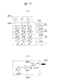
- FIG. 21 is a circuit diagram showing a circuit configuration of the cell array 206 and the reference circuit 1901.
- FIG. 21A shows a circuit configuration of the cell array 206, the selection circuit 205, and the readout circuit 209.
- the signals O1 to O3 output from the readout circuit 209 are signals with reduced background.
- the reference circuit 1901 includes a reference cell 2000 and a unit readout circuit 503 as in FIG. Further, the reference circuit 1901 includes a differential amplifier circuit (differential amplifier) 2102 that amplifies the difference between the reference signal DR from the unit readout circuit 503 and the reference voltage VRR. VR is applied to the reference electrode 100 as a reference voltage VREF.
- FIG. 21 shows the time variation of the voltage V R applied from the reference circuit 1901 to the reference electrode 100.
- the signal V D1 in which the background and the extension signal V SIG are superimposed is output from the cell 121 in which the extension reaction has occurred.
- a reference voltage VRR the voltage V R minus the signal V DR including only background measured in the reference cell 2000 is output.
- the reference voltage VREF of the reference electrode 100 is controlled by the controller 212. Therefore, the voltage V R from the reference circuit 1901 is supplied to the controller 212, according to the voltage V R from the reference circuit 1901, may be as to control the reference voltage VREF controller 212 is applied to the reference electrode 100. Further, the reference cell 2000 may be provided in the cell array 206. In this case, the controller 212 controls the reference voltage VREF applied to the reference electrode 100 so as to suppress the change (background) in the measurement value of the reference cell 2000.
Abstract
La présente invention concerne un dispositif de mesure de biomolécules équipé d'un dispositif (203) d'apport de fluide qui transmet un réactif qui réagit chimiquement avec un échantillon de biomolécules et qui produit des ions, un réseau (206) de cellules qui comprend une pluralité de capteurs semi-conducteurs qui sont disposés dans une matrice et qui mesurent la concentration en ions, et un mécanisme (207) de régulation de la température qui régule la température d'une pluralité de puits qui sont disposés sur la pluralité de capteurs semi-conducteurs et qui sont remplis d'une solution qui comprend l'échantillon de biomolécules qui est injecté à partir du dispositif (203) d'apport de fluide. Le dispositif de mesure de biomolécules est également équipé d'un dispositif de commande (212) qui commande le dispositif (203) d'apport de fluide et le mécanisme (207) de régulation de la température. Le dispositif de commande (212) commande le mécanisme (207) de régulation de la température de sorte que la différence entre la quantité de chaleur fournie à la solution dans les puits et la quantité de chaleur qui émane de la solution dans les puits soit identique pour chacun des puits de la pluralité de puits.
Applications Claiming Priority (2)
| Application Number | Priority Date | Filing Date | Title |
|---|---|---|---|
| JP2013196186A JP6247064B2 (ja) | 2013-09-20 | 2013-09-20 | 生体分子計測装置 |
| JP2013-196186 | 2013-09-20 |
Publications (1)
| Publication Number | Publication Date |
|---|---|
| WO2015040930A1 true WO2015040930A1 (fr) | 2015-03-26 |
Family
ID=52688590
Family Applications (1)
| Application Number | Title | Priority Date | Filing Date |
|---|---|---|---|
| PCT/JP2014/067708 WO2015040930A1 (fr) | 2013-09-20 | 2014-07-02 | Dispositif de mesure de biomolécules |
Country Status (2)
| Country | Link |
|---|---|
| JP (1) | JP6247064B2 (fr) |
| WO (1) | WO2015040930A1 (fr) |
Cited By (3)
| Publication number | Priority date | Publication date | Assignee | Title |
|---|---|---|---|---|
| WO2020243077A1 (fr) * | 2019-05-31 | 2020-12-03 | Illumina, Inc. | Cytomètre en flux avec une ou plusieurs fonctionnalités de barrière |
| WO2021024416A1 (fr) * | 2019-08-07 | 2021-02-11 | 株式会社日立ハイテク | Procédé de réglage de cytométrie de flux |
| CN113809106A (zh) * | 2020-08-31 | 2021-12-17 | 台湾积体电路制造股份有限公司 | 集成电路及其制造方法 |
Families Citing this family (7)
| Publication number | Priority date | Publication date | Assignee | Title |
|---|---|---|---|---|
| US10386315B2 (en) * | 2016-04-19 | 2019-08-20 | Malvern Panalytical Inc. | Differential scanning calorimetry method and apparatus |
| US11493472B2 (en) | 2017-10-11 | 2022-11-08 | Sony Semiconductor Solutions Corporation | Sensor device and measurement apparatus |
| JP2020022407A (ja) * | 2018-08-08 | 2020-02-13 | ソニーセミコンダクタソリューションズ株式会社 | 計測装置および計測システム |
| JP7219919B2 (ja) * | 2019-05-20 | 2023-02-09 | 日本航空電子工業株式会社 | 触媒反応生成物の電気化学的測定方法及びトランスデューサ |
| JP7201178B2 (ja) * | 2019-06-13 | 2023-01-10 | 日本航空電子工業株式会社 | 触媒反応生成物の電気化学的測定方法、電気化学測定装置及びトランスデューサ |
| US20230067667A1 (en) * | 2021-08-30 | 2023-03-02 | Visera Technologies Company Limited | Biosensor structure, biosensor system, and method for forming biosensor |
| KR102568395B1 (ko) * | 2021-09-23 | 2023-08-21 | 주식회사 수젠텍 | 다채널 인큐베이터 |
Citations (2)
| Publication number | Priority date | Publication date | Assignee | Title |
|---|---|---|---|---|
| JP2003505663A (ja) * | 1999-07-30 | 2003-02-12 | バイオ−ラッド ラボラトリーズ,インコーポレイティド | 多数の容器を有する反応装置のための温度制御 |
| JP2012528329A (ja) * | 2009-05-29 | 2012-11-12 | ライフ テクノロジーズ コーポレーション | 電気化学的反応を行うための装置および方法 |
Family Cites Families (3)
| Publication number | Priority date | Publication date | Assignee | Title |
|---|---|---|---|---|
| JP2003322630A (ja) * | 2002-05-01 | 2003-11-14 | Seiko Epson Corp | バイオセンサ、バイオセンシングシステム、及びバイオセンシング方法 |
| CN106591103B (zh) * | 2011-12-01 | 2021-06-04 | 吉纳普赛斯股份有限公司 | 用于高效电子测序与检测的系统和方法 |
| GB201212775D0 (en) * | 2012-07-18 | 2012-08-29 | Dna Electronics Ltd | Sensing apparatus and method |
-
2013
- 2013-09-20 JP JP2013196186A patent/JP6247064B2/ja active Active
-
2014
- 2014-07-02 WO PCT/JP2014/067708 patent/WO2015040930A1/fr active Application Filing
Patent Citations (2)
| Publication number | Priority date | Publication date | Assignee | Title |
|---|---|---|---|---|
| JP2003505663A (ja) * | 1999-07-30 | 2003-02-12 | バイオ−ラッド ラボラトリーズ,インコーポレイティド | 多数の容器を有する反応装置のための温度制御 |
| JP2012528329A (ja) * | 2009-05-29 | 2012-11-12 | ライフ テクノロジーズ コーポレーション | 電気化学的反応を行うための装置および方法 |
Cited By (11)
| Publication number | Priority date | Publication date | Assignee | Title |
|---|---|---|---|---|
| WO2020243077A1 (fr) * | 2019-05-31 | 2020-12-03 | Illumina, Inc. | Cytomètre en flux avec une ou plusieurs fonctionnalités de barrière |
| US11143638B2 (en) | 2019-05-31 | 2021-10-12 | Illumina, Inc. | Flow cell with one or more barrier features |
| US11402358B2 (en) | 2019-05-31 | 2022-08-02 | Illumina, Inc. | Flow cell with one or more barrier features |
| US11604175B2 (en) | 2019-05-31 | 2023-03-14 | Illumina, Inc. | Flow cell with one or more barrier features |
| US11867672B2 (en) | 2019-05-31 | 2024-01-09 | Illumina, Inc. | Flow cell with one or more barrier features |
| WO2021024416A1 (fr) * | 2019-08-07 | 2021-02-11 | 株式会社日立ハイテク | Procédé de réglage de cytométrie de flux |
| CN113809106A (zh) * | 2020-08-31 | 2021-12-17 | 台湾积体电路制造股份有限公司 | 集成电路及其制造方法 |
| US20220065812A1 (en) * | 2020-08-31 | 2022-03-03 | Taiwan Semiconductor Manufacturing Co., Ltd. | Integrated circuit with biofets and fabrication thereof |
| US11860120B2 (en) * | 2020-08-31 | 2024-01-02 | Taiwan Semiconductor Manufacturing Co., Ltd. | Integrated circuit with biofets and fabrication thereof |
| US11860121B2 (en) | 2020-08-31 | 2024-01-02 | Taiwan Semiconductor Manufacturing Co., Ltd. | Integrated circuit with BioFETs |
| CN113809106B (zh) * | 2020-08-31 | 2024-05-07 | 台湾积体电路制造股份有限公司 | 集成电路及其制造方法 |
Also Published As
| Publication number | Publication date |
|---|---|
| JP2015059929A (ja) | 2015-03-30 |
| JP6247064B2 (ja) | 2017-12-13 |
Similar Documents
| Publication | Publication Date | Title |
|---|---|---|
| JP6247064B2 (ja) | 生体分子計測装置 | |
| US10429342B2 (en) | Chemically-sensitive field effect transistor | |
| US20230101252A1 (en) | Apparatus and methods for performing electrochemical reactions | |
| JP6030153B2 (ja) | 生体分子計測装置 | |
| JP5889306B2 (ja) | 化学的検出システムの温度制御法 | |
| JP5205802B2 (ja) | リアルタイムpcr装置 | |
| CN107407656B (zh) | 使用大规模 fet 阵列测量分析物的方法和装置 | |
| EP2008717B1 (fr) | Dispositif de réaction avec régulation précise de la température | |
| US11193098B2 (en) | PCR apparatus comprising repeated sliding means and PCR method using same | |
| US10710084B2 (en) | PCR module, PCR system having the same, and method of inspecting using the same | |
| US20150168234A1 (en) | Microfluidic device and measured-temperature correcting method for the microfluidic device | |
| US20170081712A1 (en) | Systems and methods for analysis of nucleic acids | |
| JP5820144B2 (ja) | マイクロ流体デバイスおよび、これを用いたマイクロ流体装置 | |
| JP2008278832A (ja) | リアルタイムpcr装置 | |
| JP2000342264A (ja) | ポリヌクレオチド検出チップ及びポリヌクレオチド検査装置 | |
| US20140038189A1 (en) | Method of determining homozygote and heterozygote | |
| EP4019133B1 (fr) | Dispositif microfluidique et procédé d'amplification d'acide nucléique | |
| JP2009000014A (ja) | 反応処理装置 | |
| JP2009095755A (ja) | 反応処理装置 | |
| JP2004219271A (ja) | 解析用デバイス、SNPsの同定用デバイス、液体供給装置、検査デバイス、温度処理装置 | |
| JP2009089675A (ja) | 反応処理装置及び反応検出方法 | |
| Teh et al. | Microfluidic Flow-Through Reactor with Electrochemical Sensor Array for Real-Time Pcr | |
| JP2016019503A (ja) | デバイスの温度制御方法、温度制御装置、分析装置、および分析システム | |
| JP2015075365A (ja) | 加熱デバイス |
Legal Events
| Date | Code | Title | Description |
|---|---|---|---|
| 121 | Ep: the epo has been informed by wipo that ep was designated in this application |
Ref document number: 14845671 Country of ref document: EP Kind code of ref document: A1 |
|
| NENP | Non-entry into the national phase |
Ref country code: DE |
|
| 122 | Ep: pct application non-entry in european phase |
Ref document number: 14845671 Country of ref document: EP Kind code of ref document: A1 |