WO2015037292A1 - 電動車両の回転電機駆動システム、バッテリシステムおよび回転電機制御装置 - Google Patents
電動車両の回転電機駆動システム、バッテリシステムおよび回転電機制御装置 Download PDFInfo
- Publication number
- WO2015037292A1 WO2015037292A1 PCT/JP2014/065406 JP2014065406W WO2015037292A1 WO 2015037292 A1 WO2015037292 A1 WO 2015037292A1 JP 2014065406 W JP2014065406 W JP 2014065406W WO 2015037292 A1 WO2015037292 A1 WO 2015037292A1
- Authority
- WO
- WIPO (PCT)
- Prior art keywords
- battery
- cell
- open circuit
- circuit voltage
- voltage
- Prior art date
- Legal status (The legal status is an assumption and is not a legal conclusion. Google has not performed a legal analysis and makes no representation as to the accuracy of the status listed.)
- Ceased
Links
Images


Classifications
-
- H—ELECTRICITY
- H01—ELECTRIC ELEMENTS
- H01M—PROCESSES OR MEANS, e.g. BATTERIES, FOR THE DIRECT CONVERSION OF CHEMICAL ENERGY INTO ELECTRICAL ENERGY
- H01M10/00—Secondary cells; Manufacture thereof
- H01M10/42—Methods or arrangements for servicing or maintenance of secondary cells or secondary half-cells
- H01M10/48—Accumulators combined with arrangements for measuring, testing or indicating the condition of cells, e.g. the level or density of the electrolyte
- H01M10/482—Accumulators combined with arrangements for measuring, testing or indicating the condition of cells, e.g. the level or density of the electrolyte for several batteries or cells simultaneously or sequentially
-
- B—PERFORMING OPERATIONS; TRANSPORTING
- B60—VEHICLES IN GENERAL
- B60L—PROPULSION OF ELECTRICALLY-PROPELLED VEHICLES; SUPPLYING ELECTRIC POWER FOR AUXILIARY EQUIPMENT OF ELECTRICALLY-PROPELLED VEHICLES; ELECTRODYNAMIC BRAKE SYSTEMS FOR VEHICLES IN GENERAL; MAGNETIC SUSPENSION OR LEVITATION FOR VEHICLES; MONITORING OPERATING VARIABLES OF ELECTRICALLY-PROPELLED VEHICLES; ELECTRIC SAFETY DEVICES FOR ELECTRICALLY-PROPELLED VEHICLES
- B60L15/00—Methods, circuits, or devices for controlling the traction-motor speed of electrically-propelled vehicles
- B60L15/20—Methods, circuits, or devices for controlling the traction-motor speed of electrically-propelled vehicles for control of the vehicle or its driving motor to achieve a desired performance, e.g. speed, torque, programmed variation of speed
-
- B—PERFORMING OPERATIONS; TRANSPORTING
- B60—VEHICLES IN GENERAL
- B60L—PROPULSION OF ELECTRICALLY-PROPELLED VEHICLES; SUPPLYING ELECTRIC POWER FOR AUXILIARY EQUIPMENT OF ELECTRICALLY-PROPELLED VEHICLES; ELECTRODYNAMIC BRAKE SYSTEMS FOR VEHICLES IN GENERAL; MAGNETIC SUSPENSION OR LEVITATION FOR VEHICLES; MONITORING OPERATING VARIABLES OF ELECTRICALLY-PROPELLED VEHICLES; ELECTRIC SAFETY DEVICES FOR ELECTRICALLY-PROPELLED VEHICLES
- B60L3/00—Electric devices on electrically-propelled vehicles for safety purposes; Monitoring operating variables, e.g. speed, deceleration or energy consumption
- B60L3/0023—Detecting, eliminating, remedying or compensating for drive train abnormalities, e.g. failures within the drive train
- B60L3/0046—Detecting, eliminating, remedying or compensating for drive train abnormalities, e.g. failures within the drive train relating to electric energy storage systems, e.g. batteries or capacitors
-
- B—PERFORMING OPERATIONS; TRANSPORTING
- B60—VEHICLES IN GENERAL
- B60L—PROPULSION OF ELECTRICALLY-PROPELLED VEHICLES; SUPPLYING ELECTRIC POWER FOR AUXILIARY EQUIPMENT OF ELECTRICALLY-PROPELLED VEHICLES; ELECTRODYNAMIC BRAKE SYSTEMS FOR VEHICLES IN GENERAL; MAGNETIC SUSPENSION OR LEVITATION FOR VEHICLES; MONITORING OPERATING VARIABLES OF ELECTRICALLY-PROPELLED VEHICLES; ELECTRIC SAFETY DEVICES FOR ELECTRICALLY-PROPELLED VEHICLES
- B60L58/00—Methods or circuit arrangements for monitoring or controlling batteries or fuel cells, specially adapted for electric vehicles
- B60L58/10—Methods or circuit arrangements for monitoring or controlling batteries or fuel cells, specially adapted for electric vehicles for monitoring or controlling batteries
- B60L58/12—Methods or circuit arrangements for monitoring or controlling batteries or fuel cells, specially adapted for electric vehicles for monitoring or controlling batteries responding to state of charge [SoC]
-
- B—PERFORMING OPERATIONS; TRANSPORTING
- B60—VEHICLES IN GENERAL
- B60L—PROPULSION OF ELECTRICALLY-PROPELLED VEHICLES; SUPPLYING ELECTRIC POWER FOR AUXILIARY EQUIPMENT OF ELECTRICALLY-PROPELLED VEHICLES; ELECTRODYNAMIC BRAKE SYSTEMS FOR VEHICLES IN GENERAL; MAGNETIC SUSPENSION OR LEVITATION FOR VEHICLES; MONITORING OPERATING VARIABLES OF ELECTRICALLY-PROPELLED VEHICLES; ELECTRIC SAFETY DEVICES FOR ELECTRICALLY-PROPELLED VEHICLES
- B60L58/00—Methods or circuit arrangements for monitoring or controlling batteries or fuel cells, specially adapted for electric vehicles
- B60L58/10—Methods or circuit arrangements for monitoring or controlling batteries or fuel cells, specially adapted for electric vehicles for monitoring or controlling batteries
- B60L58/18—Methods or circuit arrangements for monitoring or controlling batteries or fuel cells, specially adapted for electric vehicles for monitoring or controlling batteries of two or more battery modules
- B60L58/21—Methods or circuit arrangements for monitoring or controlling batteries or fuel cells, specially adapted for electric vehicles for monitoring or controlling batteries of two or more battery modules having the same nominal voltage
-
- B—PERFORMING OPERATIONS; TRANSPORTING
- B60—VEHICLES IN GENERAL
- B60L—PROPULSION OF ELECTRICALLY-PROPELLED VEHICLES; SUPPLYING ELECTRIC POWER FOR AUXILIARY EQUIPMENT OF ELECTRICALLY-PROPELLED VEHICLES; ELECTRODYNAMIC BRAKE SYSTEMS FOR VEHICLES IN GENERAL; MAGNETIC SUSPENSION OR LEVITATION FOR VEHICLES; MONITORING OPERATING VARIABLES OF ELECTRICALLY-PROPELLED VEHICLES; ELECTRIC SAFETY DEVICES FOR ELECTRICALLY-PROPELLED VEHICLES
- B60L58/00—Methods or circuit arrangements for monitoring or controlling batteries or fuel cells, specially adapted for electric vehicles
- B60L58/10—Methods or circuit arrangements for monitoring or controlling batteries or fuel cells, specially adapted for electric vehicles for monitoring or controlling batteries
- B60L58/24—Methods or circuit arrangements for monitoring or controlling batteries or fuel cells, specially adapted for electric vehicles for monitoring or controlling batteries for controlling the temperature of batteries
-
- B—PERFORMING OPERATIONS; TRANSPORTING
- B60—VEHICLES IN GENERAL
- B60L—PROPULSION OF ELECTRICALLY-PROPELLED VEHICLES; SUPPLYING ELECTRIC POWER FOR AUXILIARY EQUIPMENT OF ELECTRICALLY-PROPELLED VEHICLES; ELECTRODYNAMIC BRAKE SYSTEMS FOR VEHICLES IN GENERAL; MAGNETIC SUSPENSION OR LEVITATION FOR VEHICLES; MONITORING OPERATING VARIABLES OF ELECTRICALLY-PROPELLED VEHICLES; ELECTRIC SAFETY DEVICES FOR ELECTRICALLY-PROPELLED VEHICLES
- B60L7/00—Electrodynamic brake systems for vehicles in general
- B60L7/10—Dynamic electric regenerative braking
- B60L7/14—Dynamic electric regenerative braking for vehicles propelled by AC motors
-
- H—ELECTRICITY
- H01—ELECTRIC ELEMENTS
- H01M—PROCESSES OR MEANS, e.g. BATTERIES, FOR THE DIRECT CONVERSION OF CHEMICAL ENERGY INTO ELECTRICAL ENERGY
- H01M10/00—Secondary cells; Manufacture thereof
- H01M10/42—Methods or arrangements for servicing or maintenance of secondary cells or secondary half-cells
- H01M10/44—Methods for charging or discharging
- H01M10/441—Methods for charging or discharging for several batteries or cells simultaneously or sequentially
-
- H—ELECTRICITY
- H02—GENERATION; CONVERSION OR DISTRIBUTION OF ELECTRIC POWER
- H02J—CIRCUIT ARRANGEMENTS OR SYSTEMS FOR SUPPLYING OR DISTRIBUTING ELECTRIC POWER; SYSTEMS FOR STORING ELECTRIC ENERGY
- H02J7/00—Circuit arrangements for charging or depolarising batteries or for supplying loads from batteries
- H02J7/0013—Circuit arrangements for charging or depolarising batteries or for supplying loads from batteries acting upon several batteries simultaneously or sequentially
-
- H—ELECTRICITY
- H02—GENERATION; CONVERSION OR DISTRIBUTION OF ELECTRIC POWER
- H02J—CIRCUIT ARRANGEMENTS OR SYSTEMS FOR SUPPLYING OR DISTRIBUTING ELECTRIC POWER; SYSTEMS FOR STORING ELECTRIC ENERGY
- H02J7/00—Circuit arrangements for charging or depolarising batteries or for supplying loads from batteries
- H02J7/0029—Circuit arrangements for charging or depolarising batteries or for supplying loads from batteries with safety or protection devices or circuits
- H02J7/00308—Overvoltage protection
-
- H—ELECTRICITY
- H02—GENERATION; CONVERSION OR DISTRIBUTION OF ELECTRIC POWER
- H02J—CIRCUIT ARRANGEMENTS OR SYSTEMS FOR SUPPLYING OR DISTRIBUTING ELECTRIC POWER; SYSTEMS FOR STORING ELECTRIC ENERGY
- H02J7/00—Circuit arrangements for charging or depolarising batteries or for supplying loads from batteries
- H02J7/0047—Circuit arrangements for charging or depolarising batteries or for supplying loads from batteries with monitoring or indicating devices or circuits
- H02J7/0048—Detection of remaining charge capacity or state of charge [SOC]
-
- H—ELECTRICITY
- H02—GENERATION; CONVERSION OR DISTRIBUTION OF ELECTRIC POWER
- H02J—CIRCUIT ARRANGEMENTS OR SYSTEMS FOR SUPPLYING OR DISTRIBUTING ELECTRIC POWER; SYSTEMS FOR STORING ELECTRIC ENERGY
- H02J7/00—Circuit arrangements for charging or depolarising batteries or for supplying loads from batteries
- H02J7/14—Circuit arrangements for charging or depolarising batteries or for supplying loads from batteries for charging batteries from dynamo-electric generators driven at varying speed, e.g. on vehicle
- H02J7/1423—Circuit arrangements for charging or depolarising batteries or for supplying loads from batteries for charging batteries from dynamo-electric generators driven at varying speed, e.g. on vehicle with multiple batteries
-
- B—PERFORMING OPERATIONS; TRANSPORTING
- B60—VEHICLES IN GENERAL
- B60L—PROPULSION OF ELECTRICALLY-PROPELLED VEHICLES; SUPPLYING ELECTRIC POWER FOR AUXILIARY EQUIPMENT OF ELECTRICALLY-PROPELLED VEHICLES; ELECTRODYNAMIC BRAKE SYSTEMS FOR VEHICLES IN GENERAL; MAGNETIC SUSPENSION OR LEVITATION FOR VEHICLES; MONITORING OPERATING VARIABLES OF ELECTRICALLY-PROPELLED VEHICLES; ELECTRIC SAFETY DEVICES FOR ELECTRICALLY-PROPELLED VEHICLES
- B60L2240/00—Control parameters of input or output; Target parameters
- B60L2240/40—Drive Train control parameters
- B60L2240/42—Drive Train control parameters related to electric machines
- B60L2240/421—Speed
-
- B—PERFORMING OPERATIONS; TRANSPORTING
- B60—VEHICLES IN GENERAL
- B60L—PROPULSION OF ELECTRICALLY-PROPELLED VEHICLES; SUPPLYING ELECTRIC POWER FOR AUXILIARY EQUIPMENT OF ELECTRICALLY-PROPELLED VEHICLES; ELECTRODYNAMIC BRAKE SYSTEMS FOR VEHICLES IN GENERAL; MAGNETIC SUSPENSION OR LEVITATION FOR VEHICLES; MONITORING OPERATING VARIABLES OF ELECTRICALLY-PROPELLED VEHICLES; ELECTRIC SAFETY DEVICES FOR ELECTRICALLY-PROPELLED VEHICLES
- B60L2240/00—Control parameters of input or output; Target parameters
- B60L2240/40—Drive Train control parameters
- B60L2240/42—Drive Train control parameters related to electric machines
- B60L2240/423—Torque
-
- B—PERFORMING OPERATIONS; TRANSPORTING
- B60—VEHICLES IN GENERAL
- B60L—PROPULSION OF ELECTRICALLY-PROPELLED VEHICLES; SUPPLYING ELECTRIC POWER FOR AUXILIARY EQUIPMENT OF ELECTRICALLY-PROPELLED VEHICLES; ELECTRODYNAMIC BRAKE SYSTEMS FOR VEHICLES IN GENERAL; MAGNETIC SUSPENSION OR LEVITATION FOR VEHICLES; MONITORING OPERATING VARIABLES OF ELECTRICALLY-PROPELLED VEHICLES; ELECTRIC SAFETY DEVICES FOR ELECTRICALLY-PROPELLED VEHICLES
- B60L2240/00—Control parameters of input or output; Target parameters
- B60L2240/40—Drive Train control parameters
- B60L2240/52—Drive Train control parameters related to converters
- B60L2240/527—Voltage
-
- B—PERFORMING OPERATIONS; TRANSPORTING
- B60—VEHICLES IN GENERAL
- B60L—PROPULSION OF ELECTRICALLY-PROPELLED VEHICLES; SUPPLYING ELECTRIC POWER FOR AUXILIARY EQUIPMENT OF ELECTRICALLY-PROPELLED VEHICLES; ELECTRODYNAMIC BRAKE SYSTEMS FOR VEHICLES IN GENERAL; MAGNETIC SUSPENSION OR LEVITATION FOR VEHICLES; MONITORING OPERATING VARIABLES OF ELECTRICALLY-PROPELLED VEHICLES; ELECTRIC SAFETY DEVICES FOR ELECTRICALLY-PROPELLED VEHICLES
- B60L2240/00—Control parameters of input or output; Target parameters
- B60L2240/40—Drive Train control parameters
- B60L2240/52—Drive Train control parameters related to converters
- B60L2240/529—Current
-
- B—PERFORMING OPERATIONS; TRANSPORTING
- B60—VEHICLES IN GENERAL
- B60L—PROPULSION OF ELECTRICALLY-PROPELLED VEHICLES; SUPPLYING ELECTRIC POWER FOR AUXILIARY EQUIPMENT OF ELECTRICALLY-PROPELLED VEHICLES; ELECTRODYNAMIC BRAKE SYSTEMS FOR VEHICLES IN GENERAL; MAGNETIC SUSPENSION OR LEVITATION FOR VEHICLES; MONITORING OPERATING VARIABLES OF ELECTRICALLY-PROPELLED VEHICLES; ELECTRIC SAFETY DEVICES FOR ELECTRICALLY-PROPELLED VEHICLES
- B60L2240/00—Control parameters of input or output; Target parameters
- B60L2240/40—Drive Train control parameters
- B60L2240/54—Drive Train control parameters related to batteries
- B60L2240/545—Temperature
-
- B—PERFORMING OPERATIONS; TRANSPORTING
- B60—VEHICLES IN GENERAL
- B60L—PROPULSION OF ELECTRICALLY-PROPELLED VEHICLES; SUPPLYING ELECTRIC POWER FOR AUXILIARY EQUIPMENT OF ELECTRICALLY-PROPELLED VEHICLES; ELECTRODYNAMIC BRAKE SYSTEMS FOR VEHICLES IN GENERAL; MAGNETIC SUSPENSION OR LEVITATION FOR VEHICLES; MONITORING OPERATING VARIABLES OF ELECTRICALLY-PROPELLED VEHICLES; ELECTRIC SAFETY DEVICES FOR ELECTRICALLY-PROPELLED VEHICLES
- B60L2240/00—Control parameters of input or output; Target parameters
- B60L2240/40—Drive Train control parameters
- B60L2240/54—Drive Train control parameters related to batteries
- B60L2240/547—Voltage
-
- B—PERFORMING OPERATIONS; TRANSPORTING
- B60—VEHICLES IN GENERAL
- B60L—PROPULSION OF ELECTRICALLY-PROPELLED VEHICLES; SUPPLYING ELECTRIC POWER FOR AUXILIARY EQUIPMENT OF ELECTRICALLY-PROPELLED VEHICLES; ELECTRODYNAMIC BRAKE SYSTEMS FOR VEHICLES IN GENERAL; MAGNETIC SUSPENSION OR LEVITATION FOR VEHICLES; MONITORING OPERATING VARIABLES OF ELECTRICALLY-PROPELLED VEHICLES; ELECTRIC SAFETY DEVICES FOR ELECTRICALLY-PROPELLED VEHICLES
- B60L2240/00—Control parameters of input or output; Target parameters
- B60L2240/40—Drive Train control parameters
- B60L2240/54—Drive Train control parameters related to batteries
- B60L2240/549—Current
-
- B—PERFORMING OPERATIONS; TRANSPORTING
- B60—VEHICLES IN GENERAL
- B60L—PROPULSION OF ELECTRICALLY-PROPELLED VEHICLES; SUPPLYING ELECTRIC POWER FOR AUXILIARY EQUIPMENT OF ELECTRICALLY-PROPELLED VEHICLES; ELECTRODYNAMIC BRAKE SYSTEMS FOR VEHICLES IN GENERAL; MAGNETIC SUSPENSION OR LEVITATION FOR VEHICLES; MONITORING OPERATING VARIABLES OF ELECTRICALLY-PROPELLED VEHICLES; ELECTRIC SAFETY DEVICES FOR ELECTRICALLY-PROPELLED VEHICLES
- B60L2260/00—Operating Modes
- B60L2260/40—Control modes
- B60L2260/44—Control modes by parameter estimation
-
- H—ELECTRICITY
- H01—ELECTRIC ELEMENTS
- H01M—PROCESSES OR MEANS, e.g. BATTERIES, FOR THE DIRECT CONVERSION OF CHEMICAL ENERGY INTO ELECTRICAL ENERGY
- H01M2220/00—Batteries for particular applications
- H01M2220/20—Batteries in motive systems, e.g. vehicle, ship, plane
-
- Y—GENERAL TAGGING OF NEW TECHNOLOGICAL DEVELOPMENTS; GENERAL TAGGING OF CROSS-SECTIONAL TECHNOLOGIES SPANNING OVER SEVERAL SECTIONS OF THE IPC; TECHNICAL SUBJECTS COVERED BY FORMER USPC CROSS-REFERENCE ART COLLECTIONS [XRACs] AND DIGESTS
- Y02—TECHNOLOGIES OR APPLICATIONS FOR MITIGATION OR ADAPTATION AGAINST CLIMATE CHANGE
- Y02E—REDUCTION OF GREENHOUSE GAS [GHG] EMISSIONS, RELATED TO ENERGY GENERATION, TRANSMISSION OR DISTRIBUTION
- Y02E60/00—Enabling technologies; Technologies with a potential or indirect contribution to GHG emissions mitigation
- Y02E60/10—Energy storage using batteries
-
- Y—GENERAL TAGGING OF NEW TECHNOLOGICAL DEVELOPMENTS; GENERAL TAGGING OF CROSS-SECTIONAL TECHNOLOGIES SPANNING OVER SEVERAL SECTIONS OF THE IPC; TECHNICAL SUBJECTS COVERED BY FORMER USPC CROSS-REFERENCE ART COLLECTIONS [XRACs] AND DIGESTS
- Y02—TECHNOLOGIES OR APPLICATIONS FOR MITIGATION OR ADAPTATION AGAINST CLIMATE CHANGE
- Y02T—CLIMATE CHANGE MITIGATION TECHNOLOGIES RELATED TO TRANSPORTATION
- Y02T10/00—Road transport of goods or passengers
- Y02T10/60—Other road transportation technologies with climate change mitigation effect
- Y02T10/64—Electric machine technologies in electromobility
-
- Y—GENERAL TAGGING OF NEW TECHNOLOGICAL DEVELOPMENTS; GENERAL TAGGING OF CROSS-SECTIONAL TECHNOLOGIES SPANNING OVER SEVERAL SECTIONS OF THE IPC; TECHNICAL SUBJECTS COVERED BY FORMER USPC CROSS-REFERENCE ART COLLECTIONS [XRACs] AND DIGESTS
- Y02—TECHNOLOGIES OR APPLICATIONS FOR MITIGATION OR ADAPTATION AGAINST CLIMATE CHANGE
- Y02T—CLIMATE CHANGE MITIGATION TECHNOLOGIES RELATED TO TRANSPORTATION
- Y02T10/00—Road transport of goods or passengers
- Y02T10/60—Other road transportation technologies with climate change mitigation effect
- Y02T10/70—Energy storage systems for electromobility, e.g. batteries
-
- Y—GENERAL TAGGING OF NEW TECHNOLOGICAL DEVELOPMENTS; GENERAL TAGGING OF CROSS-SECTIONAL TECHNOLOGIES SPANNING OVER SEVERAL SECTIONS OF THE IPC; TECHNICAL SUBJECTS COVERED BY FORMER USPC CROSS-REFERENCE ART COLLECTIONS [XRACs] AND DIGESTS
- Y02—TECHNOLOGIES OR APPLICATIONS FOR MITIGATION OR ADAPTATION AGAINST CLIMATE CHANGE
- Y02T—CLIMATE CHANGE MITIGATION TECHNOLOGIES RELATED TO TRANSPORTATION
- Y02T10/00—Road transport of goods or passengers
- Y02T10/60—Other road transportation technologies with climate change mitigation effect
- Y02T10/72—Electric energy management in electromobility
Definitions
- the present invention relates to a rotating electrical machine drive system, a battery system, and a rotating electrical machine control device in an electric vehicle such as an electric vehicle or a hybrid electric vehicle.
- Electric cars and hybrid electric cars are equipped with a motor as a drive source.
- Such an electric vehicle includes a motor control device that controls the torque of the inverter and the motor as a motor drive device that drives the motor.
- the motor control device transmits a control signal to the inverter to generate an alternating current for driving the motor, and controls the inverter.
- the inverter that drives the motor is driven using, for example, a battery system in which a plurality of cells made of secondary batteries or the like are connected in series as a power supply, and using the power supply as an energy source.
- the motor is driven by supplying power from the battery system, and at the time of deceleration of the vehicle, the regenerative energy generated by the regenerative operation of the motor is stored in the battery system. It is comprised so that electrical energy may be exchanged between.
- the power that can be supplied there is a limit to the power that can be supplied and the power that can be regenerated depending on the state of the cells constituting the battery system. For example, when the charging rate of the cell is in a fully charged state, the electric power regenerated by the motor cannot be accepted. Further, when the charge amount of the cell is small, power cannot be supplied to the motor.
- the cells that make up the battery system are affected by performance degradation depending on how they are used. For example, when the closed circuit voltage (CCV) of the cell becomes an overvoltage that is equal to or higher than a predetermined charge / regeneration prohibition voltage or is equal to or lower than a predetermined voltage, the cell performance deteriorates.
- CCV closed circuit voltage
- the battery system is used with restrictions so that the closed circuit voltage (CCV) of the cell does not exceed the predetermined upper limit voltage and lower than the lower limit voltage.
- CCV closed circuit voltage
- OCV open circuit voltage
- the battery monitoring device and the cell controller that monitor the amount of state of the battery system take into account the state considerations such as the cell closed circuit voltage (CCV), the total battery voltage (the battery closed circuit voltage (CCV)), and the battery current. It is necessary to detect and estimate the internal resistance and open circuit voltage (OCV) of the cell from the detected state quantity. Further, when the detection device for detecting the voltage / current in the battery monitoring device or the cell controller is abnormal, a protection system for replacing this is necessary.
- a voltage sensor that detects a closed circuit voltage (CCV) (total battery voltage) of the entire battery is provided for a battery system in which a plurality of cells are connected in series.
- CCV closed circuit voltage
- a voltage sensor that detects the voltage of the converter that boosts the battery voltage is used as an alternative to perform charge / discharge control.
- CCV closed circuit voltage
- Patent Document 1 can cope with a case where the voltage sensor that detects the total voltage of the entire battery system is abnormal, but the voltage sensor that detects the voltage of each cell can be used. If an abnormality occurs, it cannot be handled.
- a rotating electrical machine drive system that monitors a state of a plurality of cells, a rotating electrical machine that generates a driving force and a braking force of a vehicle, a plurality of cells, and at least an open circuit of each cell.
- a battery monitoring device that outputs cell state information including voltage and internal resistance, an inverter that performs power conversion in power transfer between the battery and the rotating electrical machine, a current sensor that detects the current of the rotating electrical machine, A voltage sensor that detects an applied voltage; a rotating electrical machine control unit that controls torque of the rotating electrical machine based on cell state information output from the battery monitoring device; and a battery status based on cell state information output from the battery monitoring device.
- a battery state estimation unit for estimating a state; and an abnormal state detection unit for detecting an abnormality in the cell state information.
- the open circuit voltage and internal resistance of each cell are estimated on the basis of the correlation value input from the battery monitoring device and the output of the current sensor and voltage sensor. Is detected, the torque of the rotating electrical machine is controlled based on the open circuit voltage and internal resistance of each cell estimated by the battery state estimation unit.
- the present invention even when an abnormality occurs in which cell state information cannot be obtained from the battery monitoring device, while maintaining the running of the vehicle without significantly limiting charging / discharging power or stopping power supply, all It is possible to control charging / discharging so that the closed circuit voltage of the cell is within a predetermined upper and lower limit voltage.
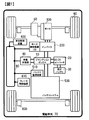
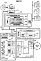
- FIG. 1 is a block diagram showing a schematic configuration of an electric vehicle 70 equipped with a rotating electrical machine drive system according to the present invention.
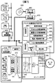
- FIG. 2 is a block diagram for explaining the rotating electrical machine drive system.
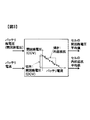
- FIG. 3 is a diagram illustrating a method for calculating the open circuit voltage average value and the internal resistance average value of the cell 570.
- FIG. 4 is a diagram illustrating a calculation process for obtaining the open circuit voltage deviation of the worst cell from the charging rate.
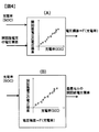
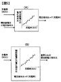
- FIG. 5 is a diagram illustrating a calculation process for obtaining the open circuit voltage relative ratio of the worst cell from the charging rate.
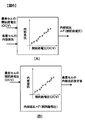
- FIG. 6 is a diagram for explaining the outline of the calculation process of the estimated internal resistance value.
- FIG. 7 shows another embodiment of the battery state estimation unit 800 provided in the motor control device 100.
- FIG. 800 shows another embodiment of the battery state estimation unit 800 provided in the motor control device 100.
- FIG. 8 is a flowchart illustrating a procedure related to torque command calculation performed by the motor control device 100.
- FIG. 9 is a diagram showing a detailed flow of the abnormality determination process in step S3 of FIG.
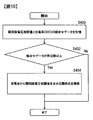
- FIG. 10 is a flowchart showing details of the correlation value calculation model creation process performed in step S4 of FIG.
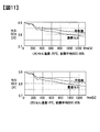
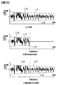
- FIG. 11 is a diagram showing the change over time of the average value of the open circuit voltage of the cell 570 and the open circuit voltage of the worst cell.
- FIG. 12 shows the relationship between the open circuit voltage relative ratio of the worst cell and the charging rate (SOC).
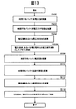
- FIG. 13 is a flowchart showing details of the correction coefficient calculation process performed in step S5 of FIG.
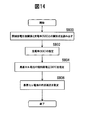
- FIG. 14 is a flowchart showing details of the worst cell state estimation process performed in step S8 of FIG. FIG.
- FIG. 15 is a flowchart showing details of the charge / discharge allowable power calculation process in step S9 of FIG.
- FIG. 16 is a time chart of the charge / discharge power value when the power limit is performed by the charge / discharge allowable power amount.
- FIG. 17 is a diagram illustrating an example of a calculation block for requested braking / driving force in the vehicle control device 400 illustrated in FIG. 2.
- FIG. 18 is a diagram illustrating a configuration when the battery state estimation unit 800 is mounted on the vehicle control device 400.
- FIG. 1 is a block diagram showing a schematic configuration of an electric vehicle 70 equipped with a rotating electrical machine drive system according to the present invention.
- the upper side is shown as the front side of the electric vehicle 70
- the lower side is shown as the rear side of the electric vehicle 70.
- the electric vehicle 70 includes a motor 300 that is a rotary motor, an inverter 200 that is a motor driving device, a motor control device 100 that outputs a control command to the inverter 200, control of the motor 300 according to various conditions such as a driver request and a battery state, A vehicle control device 400 that outputs various control commands for the entire vehicle, a battery system 500 that supplies power to the inverter 200, and the like are provided.
- the front drive configuration in which the motor 300 is mounted on the front side is shown as an example.
- the motor 300 may be arranged to drive a rear tire, or the motor may be mounted on both the front side and the rear side. Even in the case where the four-wheel drive is performed by installing 300, a configuration in which individual motors are arranged on all four wheels may be employed. The present invention can be applied regardless of differences in these configurations.
- the motor 300 is connected to the wheel 60 via the speed reducer 50.
- a brake actuator 600 that operates a friction brake (not shown) is mounted on the wheel 60, and braking can be performed using both a regenerative brake using the motor 300 and a friction brake using the brake actuator 600.
- the motor control device 100 the vehicle control device 400 that controls the entire vehicle, the brake control device 610 that calculates the command of the brake operation device 600, the battery monitoring device 510 that monitors the state of the battery system 500, and the battery system 500 with an external power source
- the on-vehicle charger 40 to be charged is connected by a control network 80.
- the motor 300 is driven by supplying electric power from the battery system 500 to the motor 300 via the inverter 200 based on a command from the motor control device 100.
- the battery system 500 is connected to the in-vehicle charger 40 and the DC / DC converter 20 via the junction box 10.
- the DC / DC converter 20 exchanges power between the battery system 500 and the low voltage battery 30.
- the battery system 500 is monitored by the battery monitoring device 510.
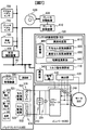
- FIG. 2 is a block diagram for explaining the rotating electrical machine drive system.
- the vehicle control device 400 that controls the entire vehicle includes detection signals from sensors such as an accelerator pedal sensor 700, a brake pedal sensor 710, and a vehicle speed sensor 720, or the state of the battery system 500 to the battery system 500, and the motor control device 100.
- the state of the motor 300 and the inverter 200 is received.
- the vehicle control device 400 calculates commands from the motor control device 100 and the brake control device 610 based on the driver operation and the vehicle state, and controls the motor control device 100 and the brake control device 610 via the control network 80. Send a command.
- the brake control device 610 determines the distribution of the regenerative brake of the friction brake 620 and the motor 300 according to the braking operation of the driver, and performs cooperative control of the regenerative brake of the friction brake 620 and the motor 300.
- FIG. 17 is a diagram illustrating an example of a calculation block for required braking / driving force in the vehicle control apparatus 400 illustrated in FIG.
- the first required braking / driving force calculation unit 611 calculates the first required braking / driving force based on the accelerator pedal sensor signal from the accelerator pedal sensor 700 and the vehicle speed sensor signal from the vehicle speed sensor 720.
- the first required braking / driving force is a braking / driving force corresponding to a driving force generated in a conventional engine-equipped vehicle or an engine brake braking force.
- the second braking / driving force calculation unit 612 calculates the second required braking / driving force based on the brake pedal sensor signal.
- the braking / driving force for the driver's braking operation is calculated, and there is a method of calculating the braking / driving force by inputting the brake pedaling force as a brake pedal sensor signal.
- the third required braking / driving force calculating unit 613 calculates the final required braking / driving force.
- the required braking / driving force calculated in FIG. 17 is transmitted to the brake control device 610 and the motor control device 100 via the control network 80.
- the brake control device 610 determines the sharing of the braking force performed by the friction brake 620 and the regenerative braking force performed by the motor 300, and the motor control device 100 Send to.
- the torque command calculation unit 110 of the motor control device 100 performs regeneration / drive required for the motor 300 based on the driving force request value from the vehicle control device 400 and the braking force request value from the brake control device 610 received by the communication unit 140. Calculate torque command.
- a torque command for the motor 300 is finally calculated.
- the torque command calculated by the torque command calculation unit 110 is transmitted to the command unit 130, and the command unit 130 outputs a drive command for the inverter 200 in order to realize the torque command.
- the battery system 500 includes battery modules 531 and 532 composed of a plurality of cells 570 (hereinafter referred to as cells), a battery monitoring device 510, cell monitoring devices 521 and 522, a temperature sensor 560, a first voltage sensor 540, One current sensor 550, a temperature sensor 560, and a communication unit 580 are included.
- the cell monitoring devices 521 and 522 detect the closed circuit voltage (CCV) that is the state of the cells 570 in the battery modules 531 and 532, and detect the state quantities of the cells 570 and the battery modules 531 and 532.
- the first voltage sensor 540 detects the total voltage of the battery modules 531 and 532.
- the first current sensor 550 detects the current flowing through the battery modules 531 and 532.
- the temperature sensor 560 detects various temperatures in the battery system 500.
- the battery monitoring device 510 uses information such as the closed circuit voltage (CCV) of the cell 570 detected by the cell monitoring devices 521 and 522, and the detection results of the temperature sensor 560, the first voltage sensor 540, and the first current sensor 550. Based on this, the entire state of the battery system 500 is detected.
- the communication unit 580 is connected to the control network 80 and exchanges signals with other control devices such as the vehicle control device 400 and the motor control device 100.
- the battery monitoring device 510 includes a total battery voltage detected by the first voltage sensor 540, a battery current detected by the first current sensor 550, an internal temperature of the battery system 500 detected by the temperature sensor 560, Using the closed circuit voltage (CCV) of each cell 570 acquired by the cell monitoring devices 521 and 522, the internal state of the battery system 500 and the internal state of the battery modules 531, 532 and the cell 570 are calculated, and the battery system 500 The status is monitored. Specifically, the average value of the open circuit voltage (OCV) and the average value of the internal resistance of the cell 570 constituting the battery are calculated from the total battery voltage and the battery current, and the individual closed circuit voltage and the battery current of the cell 570 are calculated. The open circuit voltage (OCV) of each cell 570 and the internal resistance of each cell 570 are calculated.
- the battery correlation is monitored with the voltage correlation value between the open circuit voltage (OCV) of each cell 570 and the average value of the open circuit voltage (OCV) of the cell 570.
- OCV open circuit voltage
- the calculation is performed by the device 510, and these are output to each control device connected to the control network 80 via the communication unit 580.
- the voltage correlation value (hereinafter referred to as the open circuit voltage correlation value) with the open circuit voltage (OCV) of each cell with respect to the average value of the open circuit voltage (OCV) of the cell is the open circuit voltage ( OCV) is the deviation of the open circuit voltage (OCV) of each cell from the average value of OCV) (hereinafter referred to as the open circuit voltage deviation), and the average value of the open circuit voltage (OCV) of the cell 570.
- Open circuit voltage relative ratio (hereinafter referred to as open circuit voltage relative ratio), which is the ratio of open circuit voltage (OCV) of each cell 570, open circuit voltage ratio (hereinafter referred to as open circuit voltage ratio). ) Etc.
- the battery monitoring device 510 receives the open circuit voltage correlation value (open circuit voltage deviation) in addition to the open circuit voltage of each cell 570 that is the internal state of the battery system 500 and the average value of the open circuit voltage. Or open circuit voltage ratio). By obtaining such a deviation or relative ratio from the average value of each cell 570, it is possible to use the variation of the cells 570 constituting the battery system 500 as described later.
- a plurality of cell monitoring devices 521 and 522 are provided according to the number of battery modules, and are connected to the battery monitoring device 510 by daisy chain connection.
- the result detected by the cell monitoring device 521 is transmitted to the cell monitoring device 522 and further transmitted from the cell monitoring device 522 to the next cell monitoring device.
- all the states of the cells 570 detected by the cell monitoring devices 521 and 522 are transmitted to the battery monitoring device 510 via the cell monitoring device. For this reason, it takes time to transmit all the states of all the cells 570 to the battery monitoring apparatus 510. That is, there is a time delay in the voltage detection value of each cell.
- the calculation of the open circuit voltage (OCV) and internal resistance of each cell 570 uses the voltage detection value (CCV) and battery current value of each cell 570 having a detection time delay, so the voltage detection value and battery current are calculated. Processing that synchronizes values is required. Further, since the data used for the calculation of the open circuit voltage (OCV) of each cell 570 is a signal acquired at different timings, the calculation result of the open circuit voltage (OCV) of each cell 570 differs for each cell 570. It is the result of timing.
- the deviation (open circuit voltage deviation) between the average value of the open circuit voltage (OCV) of the cell 570 and the open circuit voltage (OCV) of each cell 570 or the open circuit voltage (OCV) of the cell 570 The battery monitoring device 510 of the battery system 500 preferably calculates the ratio between the average value and the open circuit voltage (OCV) of each cell 570 (open circuit voltage relative ratio, open circuit voltage ratio).
- the battery monitoring device 510 the average value of the open circuit voltage (OCV) of the cell 570 acquired at the same timing as the result of the open circuit voltage (OCV) of each cell 570 (for example, detection by the first voltage sensor 540). (Average value obtained from the value) is obtained, and the deviation (open circuit voltage deviation) between the average value of the open circuit voltage (OCV) of the synchronized cell 570 and the open circuit voltage (OCV) of each cell 570, The ratio (open circuit voltage relative ratio, open circuit voltage ratio) of the average value of the open circuit voltage (OCV) and the open circuit voltage (OCV) of each cell 570 is calculated. As described above, it is preferable that the battery monitoring device 510 obtains the voltage correlation value by synchronizing the calculated voltage values.
- the motor control device 100 includes a torque command calculation unit 110, a detection unit 120, a command unit 130, a communication unit 140, and a battery state estimation unit 800.
- the battery state estimation unit 800 estimates the state of the battery system 500 as will be described later.
- the communication unit 140 performs transmission / reception of signals such as driving force and braking force transmitted from the vehicle control device 400, reception of data output from the battery system 500, and the like.
- the detection unit 120 takes in a rotation angle signal detected by a rotation angle sensor (not shown) installed in the motor 300 and also detects a three-phase current detected by a second current sensor 240 provided in the inverter 200. The signal and the voltage signal detected by the second voltage sensor 230 are taken in, respectively.
- the torque command calculation unit 110 is based on the driving force required value received from the vehicle control device 400 through the communication unit 140, the vehicle speed, and a signal representing the state quantity of the cell 570 or the battery modules 531 and 532 calculated by the battery monitoring device 510.
- the motor 300 and the inverter 200 are allowable, and the battery system 500 calculates an allowable torque command.
- the torque command is output to command unit 130. In the calculation of the torque command, calculation is performed so that all the cells 570 configuring the battery system 500 are not overcharged / discharged.
- command unit 130 implements a drive command (pulse width modulation (pulse width modulation)) based on the torque command and the detected value of motor 300 captured by detection unit 120.
- the drive signal corresponding to PWM is calculated.
- Inverter 200 drives inverter 200 based on the drive command from command unit 130 and controls the drive and regenerative operation of motor 300.
- the motor 300 is, for example, a permanent magnet type three-phase AC synchronous motor that uses a permanent magnet as a field, and is driven and controlled by three-phase AC power supplied from the inverter 200.
- the motor 300 functions as a generator and generates regenerative braking force. Thereby, it is possible to collect the kinetic energy of the vehicle as electric energy.
- the torque command calculation unit 110 calculates the torque command within a range that the battery system 500 can tolerate, and the chargeable / dischargeable power is obtained as follows.
- each cell 570 is described by a simplified model shown in the following equation (1) from the closed circuit voltage (CCV), open circuit voltage (OCV), internal resistance, and battery current of each cell 570.
- Vcci is a closed circuit voltage (CCV) of each cell 570
- t is time
- Voci is an open circuit voltage (OCV) of each cell 570
- Rci is an internal resistance of each cell 570
- Ib Represents the battery current. Note that the subscript i indicates an amount related to the i-th cell 570.
- the upper limit allowable value of the closed circuit voltage (CCV) of the cell 570 is Vcclimit1 [V]
- the lower limit allowable value is Vcclimit2 [V ]
- the chargeable current value Iblimit1 [A] and the dischargeable current value Iblimit2 [A] are expressed by the following equations (2) and (3): It becomes possible to obtain like this.
- the battery chargeable power Pdmax and the discharge allowable power Pcmax are expressed by the following equations (4) and (5), respectively.
- the allowable discharge power Pdmax and the charge power are determined.
- Pcmax can be calculated.
- the driving upper limit torque TrqDmax and the regeneration upper limit torque TrqCmax are obtained, whereby the closed circuit voltage of the cell 570 ( It is possible to obtain a torque command such that (CCV) does not exceed the upper and lower limit voltage.
- ⁇ is the motor / inverter efficiency
- n is the number of cells.
- a torque command can be calculated so that the closed circuit voltage (CCV) of the cell 570 does not exceed the upper and lower limit voltages. .
- the cell 570 having a large internal resistance and a small open circuit voltage (OCV) becomes a restriction on charging and discharging.
- the cell 570 having a large internal resistance and a small open circuit voltage (OCV) is generally deteriorated in many cases, but in the following, the cell 570 having a large internal resistance and a small open circuit voltage (OCV) is the worst. It will be called a cell.
- the closed circuit voltage of all the cells 570 The torque command can be set so that (CCV) does not exceed the upper and lower limit voltages.
- the motor controller 100 is provided with a battery state estimation unit 800 for estimating 500 states.
- Some abnormalities in the battery system 500 are abnormalities in the battery monitoring device 510 that monitors the state of the battery system 500, abnormalities in the first voltage sensor 540 that detects the total voltage of the battery, abnormalities in the cell monitoring devices 521 and 522, communication
- the part 580 may be abnormal.
- the battery state estimation unit 800 illustrated in FIG. 2 includes an abnormality determination unit 810 that determines whether or not the battery system 500 is abnormal, an average that calculates an alternative value of the open circuit voltage average value and an alternative value of the internal resistance average value of the cell 570.
- a value calculation unit 840 and a storage unit 860 are provided.
- the battery state estimation unit 800 calculates the open circuit voltage (OCV) and internal resistance of the worst cell necessary when the torque command calculation unit 110 calculates the torque command. That is, the first voltage sensor 540, the first current sensor 550 provided in the battery system 500, and a voltage sensor (not shown) for detecting the closed circuit voltage (CCV) of the cell 570 in the cell monitoring devices 521 and 522. ) Is abnormal, or even when the detection signal cannot be communicated from the battery system 500, a torque command is calculated so that the closed circuit voltage (CCV) of all cells 570 does not exceed the upper and lower limit voltages. In order to make this possible, the open circuit voltage (OCV), which is the state quantity of the worst cell, and the internal resistance are calculated.
- OCV open circuit voltage
- the worst cell for example, when the closed circuit voltage (CCV) of the cell 570 is acquired during charging, the cell 570 having the largest closed circuit voltage (CCV) is obtained. When the circuit voltage (CCV) is acquired, the cell 570 having the smallest closed circuit voltage (CCV) is set as the worst cell. The cell 570 having the largest estimated value of internal resistance may be the worst cell.
- the cell 570 Since the cell 570 once determined to be the worst cell is more likely to deteriorate than the other cells 570, the cell 570 is stored as the worst cell. After that, only the state quantity (open circuit voltage (OCV), closed circuit voltage, internal resistance) of the worst cell is detected or estimated. This has the effect of reducing the estimation process and the detection process.
- OCV open circuit voltage
- the abnormality determination unit 810 of the battery state estimation unit 800 determines whether or not the internal state of the battery system 500 cannot be received by another control device connected to the control network 80 due to the abnormality in the battery system 500 as described above. . A specific determination method will be described later.
- state quantities inside the battery system 500 such as the total battery voltage, the closed circuit voltage (CCV) of the cell 570, the battery current, the open circuit voltage (OCV) of the cell 570, and the internal resistance of the cell 570 cannot be obtained.
- the abnormality is called a battery system state detection abnormality.
- a normal state in which the internal state quantity of the battery system 500 can be acquired is called battery system state detection normal.
- Average cell state calculation unit 820 calculates an alternative value for the average open circuit voltage (OCV) value and an alternative value for the internal resistance average value of cell 570 when abnormality determination unit 810 determines that the battery system state detection is abnormal. .
- OCV average open circuit voltage
- the abnormality determination unit 810 determines that the battery system state detection is abnormal, the detection signal from the first voltage sensor 540 that detects the total voltage in the battery system 500 cannot be used. Therefore, the average cell state calculation unit 820 calculates the total voltage of the battery system 500 from the voltage signal detected by the second voltage sensor 230 provided between the power module 210 of the inverter 200 and the battery modules 531 and 532. Calculate the substitute signal. In addition, since the detection signal from the first current sensor 550 that detects the battery current cannot be used, instead of the current signal detected by the second current sensor 240 provided in the motor 300, the substitute signal for the battery current is used. Is calculated.
- the average cell state calculation unit 820 is based on the alternative signal of the battery total voltage and the alternative signal of the battery current, the alternative value of the open circuit voltage (OCV) average value of the cells 570 constituting the battery system 500, and the internal resistance average Calculate an alternative value.
- OCV open circuit voltage
- the drive command from the command unit 130 of the motor control device 100 is a pulse width modulation signal (PWM) signal, and a switching element (not shown) of the power module 210 of the inverter 200 is turned on / off by this PWM signal. Switch. At this time, the direct current supplied from the battery system 500 becomes one of the phase currents of the motor 300 depending on the on / off state of the switching elements constituting the power module 210.
- PWM pulse width modulation signal
- any one of the three-phase currents is approximately equal to the battery direct current. Therefore, the alternative value of the battery current can be obtained by switching the second current sensor signal for detecting the three phase currents according to the switching state determined by the PWM signal of the command unit 130 of the motor control device 100. It becomes.
- the charge rate (SOC) cannot be received from the battery monitoring device 510.
- the charging rate (SOC) substitute value is calculated.
- the open circuit voltage is calculated from the relationship between the charge rate (SOC) stored in advance and the open circuit voltage (OCV), and the relationship between the charge rate (SOC) and the internal resistance. (OCV) and internal resistance can be calculated.
- Each cell 570 is described by a simple model such as the above equation (1) from the closed circuit voltage (CCV), open circuit voltage (OCV), internal resistance, and battery current of each cell 570.
- Vcb is a closed circuit voltage (CCV) of the entire battery. That is, the total voltage.
- Voci represents the open circuit voltage (OCV) of each cell 570
- Rci represents the internal resistance of each cell 570
- Ib represents the battery current
- t represents time
- n represents the number of cells 570 connected in series.
- the subscript i represents the i-th cell 570.
- the battery current and the battery total voltage can be approximated by a linear model from the equation (8), if the values of the battery current and the battery total voltage are known, the sum of the open circuit voltages (OCV) of all the cells 570 and the internal The total resistance can be obtained.
- the least square approximation of a combination of a plurality of battery total voltage values and battery current values is used to calculate the slope as the sum of internal resistances and the intercept as the sum of open circuit voltages (OCV). be able to.
- the obtained total sum of internal resistances and total sum of open circuit voltages (OCV) are respectively divided by the number of cells, whereby the open circuit voltage average value and the internal resistance average value of the cell 570 are calculated.
- OCV open circuit voltage average value
- an operation corresponding to a change in the average open circuit voltage value and the average internal resistance value of the cell 570 can be performed.
- FIG. 3 is a diagram for explaining a method of calculating the open circuit voltage average value and the internal resistance average value of the cell 570.
- CCV closed circuit voltage
- the combination of the total battery voltage and battery current is input, and the total voltage and battery current are linearly approximated by the least squares method as shown in FIG.
- the intercept of the linear approximation line indicates the open circuit voltage (OCV) of the entire battery system, and the slope indicates the internal resistance. Therefore, it is possible to calculate the open circuit voltage (OCV) and the internal resistance of the entire battery system by inputting a combination of the battery total voltage and the battery current for a predetermined time from the current time point. Then, when the open circuit voltage (OCV) and the internal resistance of the entire battery are divided by the number of cells 570, the open circuit voltage average value and the internal resistance average value of the cells 570 constituting the battery system 500 are obtained.
- the abnormality determination unit 810 determines that the battery system state detection is normal, as described above, the open circuit voltage average value of the cell 570 and the average value of the cell 570 from the battery system 500 via the control network 80.
- the average value of internal resistance can be obtained.
- the average cell state calculation unit 820 determines the total voltage substitute signal calculated based on the detection value of the second voltage sensor 230 and the second current sensor.
- the above-described processing shown in FIG. 3 is performed using the battery current substitute signal calculated based on the detected value of 240, thereby substituting the substitute value of the open circuit voltage average value and the internal resistance average value of the cell 570. Calculate the value.
- the correlation value calculation unit 840 determines the charging rate (SOC) and the voltage correlation value (voltage deviation or voltage relative ratio) of the open circuit voltage (OCV) of the worst cell based on the data acquired when the battery system state detection is normal. Build a relationship.
- the correlation value calculation unit 840 obtains combination data of the open circuit voltage correlation value of the cell 570 acquired from the battery monitoring device 510 and the charging rate at that time. It memorize
- SOC charging rate
- the open circuit voltage correlation value is a deviation of the open circuit voltage (OCV) of each cell 570 from the average value of the open circuit voltage (OCV) of the cell 570 (hereinafter referred to as an open circuit voltage deviation) or The ratio of the open circuit voltage (OCV) of the cell 570 to the average value of the open circuit voltage (OCV) of the cell 570 (hereinafter referred to as the open circuit voltage relative ratio).
- the above-described information cannot be acquired from the battery system 500. Therefore, the combination data of the open circuit voltage correlation value and the charging rate (SOC) is stored, and the charging rate (SOC ) And the open circuit voltage correlation value are not updated.
- charging / discharging of the battery system 500 is limited by the worst cell having the lowest battery capacity and the largest internal resistance. Therefore, the combination data of the open circuit voltage correlation value and the charging rate (SOC) of each cell 570 may be stored. However, the worst cell among the cells 570 is specified, and the open circuit voltage correlation of the worst cell is determined. Only the combination data of the value and the charging rate (SOC) may be stored in the storage unit 860. In this case, the data to be stored can be reduced, and the storage capacity of the storage unit 860 can be reduced.
- the open circuit voltage deviation of the worst cell with respect to the average open circuit voltage value of the cell 570 varies depending on the state of the worst cell. For example, when an open circuit voltage deviation occurs due to deterioration, the open circuit voltage deviation with respect to the charging rate (SOC) changes as the deterioration changes. Therefore, it is preferable to use the latest data combination group acquired as recently as possible for the combination of the charging rate (SOC) and the open circuit voltage deviation of the worst cell.
- FIG. 4B is a diagram for explaining the operation of the correlation value calculation unit 840 in the case of battery system state detection abnormality.
- the correlation value calculation unit 840 charging rate as follows (SOC) calculates a substitute value, the charging rate was constructed at the battery system state detection normal relationship of (SOC) and the open circuit voltage deviation (9)
- SOC charge rate
- the battery current substitute signal is calculated from the current signal detected by the second current sensor 240, the charge / discharge amount is obtained from the battery current substitute signal, and the charge rate (SOC) change amount is calculated. Then, based on the amount of change in the charging rate (SOC) and the charging rate (SOC) received from the battery monitoring device 510 before the battery system state detection abnormality occurs, the charging rate (SOC) substitute value at each time Is calculated.
- the charging rate of the entire battery system 500 can be estimated from the average value of the open circuit voltage (OCV) of the cell 570.
- FIG. 5A shows the relationship between the charging rate (SOC) and the open circuit voltage relative ratio of the worst cell, which is constructed by the correlation value calculation unit 840 when the battery system state detection is normal.
- SOC charging rate
- SOC open circuit voltage relative ratio
- the charging rate (SOC) is VSOC
- the open circuit voltage relative ratio of the worst cell is RateVOCV.
- the open circuit voltage relative ratio of the worst cell varies depending on the state of the worst cell. For example, when the voltage relative ratio of the open circuit voltage occurs due to deterioration, the voltage relative ratio of the open circuit voltage to the charging rate (SOC) changes as the deterioration changes. Therefore, it is preferable to use the latest data combination group acquired as recently as possible for the combination of the charging rate (SOC) and the open circuit voltage relative ratio of the worst cell.
- FIG. 5B is a diagram for explaining the operation of the correlation value calculation unit 840 in the case of abnormal battery system state detection.
- the above charge rate (SOC) substitute value is input to the relational expression (10) for estimating the open circuit voltage relative ratio of the worst cell from the charge rate (SOC) constructed in FIG.
- the voltage relative ratio of the open circuit voltage (OCV) of the worst cell is calculated.
- Worst cell state calculation unit 830 calculates the open circuit voltage (OCV) and internal resistance of the worst cell in the case of battery system state detection abnormality.
- the open circuit voltage (OCV) and internal resistance of each cell 570 calculated by the battery monitoring device 510 can be acquired by the control network 80.
- the open circuit voltage (OCV) and internal resistance of all the cells 570 may be acquired.
- the worst cell is the charge / discharge constraint of the battery system 500
- the open circuit voltage (OCV) of the worst cell may be acquired.
- only the internal resistance may be acquired. As a result, the amount of communication information of the control network 80 can be reduced.
- the average cell state calculation unit 820 calculates a substitute signal for the total voltage of the battery system 500 from the voltage signal detected by the second voltage sensor 230, and the second An alternative signal for the battery current is calculated from the current signal detected by the current sensor 240. Further, the average cell state calculation unit 820 replaces the open circuit voltage average value and the internal resistance average value of the cells 570 constituting the battery system 500 based on the battery total voltage replacement signal and the battery current replacement signal. Is calculated.
- the worst cell state calculation unit 830 includes the above-described charge rate (SOC) substitute value (see the description of the correlation value calculation unit 840), the substitute value of the open circuit voltage average value calculated by the average cell state calculation unit 820, and the correlation.
- SOC charge rate
- the worst cell open circuit voltage (OCV) is estimated from the relational expression between the charging rate (SOC) constructed by the value calculation unit 840 and the worst cell open circuit voltage correlation value (open circuit voltage deviation, open circuit voltage relative ratio). To do.
- the open circuit voltage relative ratio (RateVOCV) of the worst cell is obtained from the charge rate (SOC) substitute value and the correlation. Then, from this open circuit voltage relative ratio (RateVOCV) and the substitute value (VOCVave) of the above-mentioned average value of the open circuit voltage, the estimated open circuit voltage (OCV) value VOCVw of the worst cell is calculated by the equation (12).
- the VOCVw VOCVave x RateVOCV (12)
- the open circuit voltage average value of the cell 570 is calculated from the current charging rate (SOC). It is possible to determine the voltage deviation or voltage relative ratio of the open circuit voltage (OCV) of the worst cell with respect to. As a result, the open circuit voltage (OCV) of the worst cell can be estimated from the average value of the open circuit voltage (OCV) of the cell 570 and the obtained voltage deviation or voltage relative ratio of the open circuit voltage.
- the internal resistance of the worst cell is calculated from the estimated value of the open circuit voltage (OCV) of the worst cell using the map data of the open circuit voltage (OCV) of the cell 570 and the internal resistance stored in the storage unit 860. Calculate internal resistance.
- FIG. 6 is a diagram showing an outline of internal resistance calculation.
- FIG. 6A is a diagram for explaining the construction of a relational expression or table for estimating the internal resistance of the worst cell from the open circuit voltage (OCV) of the worst cell. If the worst cell open circuit voltage (OCV) and the worst cell internal resistance can be obtained (ie, normal), the combination of the worst cell open circuit voltage (OCV) and the worst cell internal resistance is stored. Memorize the relationship between internal resistance and open circuit voltage. Based on the stored data, a relational expression or table for estimating the internal resistance of the worst cell from the open circuit voltage (OCV) of the worst cell is constructed.
- the estimated value of the open circuit voltage (OCV) of the worst cell and FIG. 6B is estimated by using the relational expression F of the built-in internal resistance and the open circuit voltage (OCV) or the relation table.
- FIG. 7 shows another embodiment of the battery state estimation unit 800 provided in the motor control device 100.
- the configuration shown in FIG. 2 is different from the configuration shown in FIG. 2 in that a voltage / current correction unit 850 is provided, and the other configurations are the same.
- the voltage / current correction unit 850 will be described.
- the voltage / current correction unit 850 is an alternative value of the battery total voltage calculated from the voltage detected by the second voltage sensor 230 with respect to the battery total voltage detected by the first voltage sensor 540 provided in the battery system 500.
- the error and the error of the alternative value of the battery current calculated from the current detected by the second current sensor 240 with respect to the battery current detected by the first current sensor 550 provided in the battery system 500 are corrected.
- the total battery calculated from the total battery voltage detected by the first voltage sensor 540 and the detection voltage of the second voltage sensor 230 is used.
- the voltage correction coefficient is calculated from the error between the voltage and the alternative value.
- a current correction coefficient is calculated from an error between the battery current detected by the first current sensor 550 and the alternative value of the battery current calculated from the detected current of the second current sensor 240.
- the calculated voltage correction coefficient and current correction coefficient are stored in the storage unit 860.
- FIG. 8 is a flowchart showing a procedure related to a torque command calculation performed by the motor control device 100 in response to an abnormal battery system state detection or a normal battery system state detection.
- a series of processing shown in FIG. 8 is repeatedly executed.
- the flowchart shown in FIG. 8 shows processing in the case of the motor control device 100 including the voltage / current correction unit 850 shown in FIG.
- the process of step S5 is omitted.
- the processing in step S6 is different between the case of the motor control device 100 shown in FIG. 2 and the case of the motor control device 100 shown in FIG.
- step S ⁇ b> 1 the motor control device 100 acquires data regarding the state quantity inside the battery system 500 calculated by the battery monitoring device 510 from the battery system 500 via the control network 80. Furthermore, the motor control device 100 acquires data on the voltage applied to the inverter from the second voltage sensor 230 provided in the inverter 200 by the detection unit 120, and the second current sensor provided in the motor 300 or the inverter 200. The motor current data is acquired from 240.
- the data acquired from the battery system 500 includes (D1) battery total voltage, (D2) closed circuit voltage (CCV) of each cell 570, (D3) charge rate (SOC), (D4) open circuit voltage of the cell 570 ( OCV) average value, (D5) open circuit voltage (OCV) of each cell 570, (D6) average value of internal resistance of cell 570, (D7) internal resistance of each cell 570, (D8) battery current, (D9) There is a voltage correlation value of the open circuit voltage (OCV) of each cell 570 with respect to the average value of the open circuit voltage (OCV) of the cell 570.
- the open circuit voltage correlation value is the above-described open circuit voltage deviation or open circuit voltage relative ratio.
- various diagnoses are performed in the battery system 500, and it is also possible to receive a diagnosis result such as whether the battery system 500 is abnormal or normal from these diagnosis results.
- step S2 the inverter applied voltage acquired from the second voltage sensor 230 is used as an alternative value for the battery total voltage, and an alternative value for the battery current is obtained from the motor current acquired from the second current sensor 240. Then, using these alternative values, the alternative value of the open circuit voltage average value and the alternative value of the internal resistance average value of the cell 570 are estimated. This estimation is performed by the average cell state calculation unit 820 as described above.
- step S3 a battery system state detection abnormality in which the internal state quantity of the battery system 500 cannot be acquired based on the data acquired in step S1, the alternative value of the total battery voltage obtained in step S2, the alternative value of the battery current, and the like. It is determined whether or not the battery system state detection in which the state quantity can be acquired is normal. This determination is performed by the abnormality determination unit 810 described above. The detailed process of step 3 will be described later (FIG. 9). If it is determined in step S3 that the battery system state detection is normal, the process proceeds to step S4. If it is determined that the battery system state detection is abnormal, the process proceeds to step S6.
- step S4 the open circuit voltage correlation value (open circuit voltage deviation or open circuit voltage relative ratio) of the worst circuit open circuit voltage (OCV) to the average open circuit voltage obtained from the battery monitoring device 510 and the charging rate (SOC). Is stored in the storage unit 860. Then, based on the stored data, a relational expression (calculation model) between the above-described charging rate (SOC) and the open circuit voltage correlation value of the open circuit voltage (OCV) of the worst cell is constructed. The construction of this relational expression is performed by the correlation value calculation unit 840. Details of step 4 will be described later (FIG. 10).
- step S5 a correction coefficient used in the voltage / current correction unit 850 is calculated.
- a voltage correction coefficient is calculated from the error.
- the current correction coefficient is calculated from the error between the battery current detected by the first current sensor 550 provided in the battery system 500 and the alternative value of the battery current calculated from the detection current of the second current sensor 240. Calculate.
- step S6 differs between the configuration shown in FIG. 2 and the configuration shown in FIG.
- the voltage correction coefficient and the current correction coefficient calculated in step S ⁇ b> 5 when the battery system state detection is normal are read from the storage unit 860.
- the battery total voltage estimated value is calculated from the detected value of the second voltage sensor 230 and the read voltage correction coefficient.
- the battery current estimated value is calculated from the alternative value of the battery current estimated from the detection value of the second current sensor 240 and the read current correction coefficient.
- the detected value of the second voltage sensor 230 is set as the battery total voltage estimated value
- the detected value of the second current sensor 240 is set as the battery current estimated value.
- step S7 the battery total voltage estimated value and battery current estimated value obtained in step S6 are used as alternative values for the battery total voltage and battery current, respectively. And an open circuit voltage average value is estimated using each alternative value. Further, the average value of the internal resistance of the cell 570 is obtained. The average open circuit voltage average value and the internal resistance average value (alternative value calculation) are performed by the average cell state calculation unit 820 as described above.
- step S8 the average value of the closed circuit voltage of the cell 570 estimated in step S7, the open circuit voltage of the charge rate (SOC) and the worst cell open circuit voltage (OCV) established in step S4 when the battery system state detection is normal.
- An estimated value of the open circuit voltage (OCV) of the worst cell and an estimated value of the internal resistance are calculated using a relational expression (calculation model) with the correlation value. The calculation of these estimated values is performed by the worst cell state calculation unit 830 described above. The detailed process will be described later (FIG. 14).
- step S8 When the process of step S8 ends, the process proceeds to step S9.
- the open circuit voltage (OCV) of the worst cell calculated in step S8. ) And the estimated value of the internal resistance are used to calculate the allowable charge / discharge power that the battery system 500 can tolerate.
- step S9 if it is determined in step S3 that the battery system state detection is normal and the process proceeds to step S9 after executing the processes in steps S4 to S5, the open circuit voltage (OCV) of the worst cell acquired in step S1 and the internal Charge / discharge allowable power is calculated using a resistor.
- the calculation of the charge / discharge allowable power is performed by the torque command calculation unit 110 described above. The detailed process will be described later (FIG. 15).
- step S10 the torque command calculation unit 110 calculates the above formulas (6) and (7) from the allowable charge / discharge allowable power obtained in step S9, the motor / inverter efficiency, and the current rotational speed of the motor 300.
- the upper and lower limits (drive upper limit torque and regeneration upper limit torque) of the allowable motor torque are calculated.
- step S11 the torque command calculation unit 110 calculates a final torque command from the allowable torque upper and lower limit values obtained in step S10 and the required driving force requested from the vehicle control device 400.
- the calculated torque command is output to the command unit 130 of the motor control device 100.
- the command unit 130 outputs the motor rotation speed, torque, current, and voltage acquired from the detection unit 120 to the inverter 200 based on the torque command value.
- a drive command is calculated and the drive command is output to inverter 200.
- FIG. 9 is a diagram showing a detailed flow of the abnormality determination process in step S3 of FIG.
- step S300 it is determined whether or not the alternative value of the open circuit voltage average value and the alternative value of the internal resistance average value of the cell 570 estimated in step S2 have changed suddenly.
- the second voltage sensor 230 and the second current sensor 240 may be abnormal. There is.
- the abnormality determination of the second voltage sensor 230 and the second current sensor 240 is not limited to the above method, and the motor control device 100 can determine the abnormality using a different method. As a guideline for determining whether or not the alternative value of the open circuit voltage average value and the alternative value of the internal resistance average value are suddenly changed, for example, if the change amount exceeds about 20%, it is determined that the change is sudden.
- step S300 If it is determined in step S300 that there is a sudden change, the process proceeds to step S314.
- the second voltage sensor 230 and the second current sensor 240 may be abnormal, and the motor control cannot be performed accurately. Therefore, the flag for abnormality determination 2 is set.
- the motor cannot be controlled since the motor cannot be controlled, information indicating that the motor cannot be driven is transmitted to the host vehicle control device 400, and processing such as prohibiting control of the motor 300 is performed.
- step S300 if it is determined in step S300 that there is no sudden change, it is determined that the second voltage sensor 230 and the second current sensor 240 are normal, and the process proceeds to the next step S302.
- step S302 abnormality determination of the battery system 500, that is, whether or not the above-described battery system state detection abnormality (abnormality in which the internal state quantity of the battery system 500 cannot be acquired) is performed.
- an abnormality determination signal determined by the battery monitoring device 510 of the battery system 500 is acquired, and the determination is made based on the abnormality determination signal and a communication abnormality with the battery system 500.
- the battery monitoring device 510 the total voltage of the battery system 500 detected by the first voltage sensor 540, the battery current detected by the first current sensor 550, and the cell 570 detected by the cell monitoring devices 521 and 522.
- the abnormality of the battery system 500 is diagnosed using the closed circuit voltage (CCV) of the battery, the temperature of the cell 570 detected by the temperature sensor 560, the temperature of the battery system 500, and the like.
- the motor control device 100 acquires an abnormality determination signal that is the abnormality diagnosis result via the control network 80.
- step S302 If it is determined in step S302 that the battery system state detection is abnormal, the process proceeds to step S312 and the flag of abnormality determination 1 is set. On the other hand, if it is determined in step S302 that there is no abnormality, that is, the above-described battery system state detection is normal, the process proceeds to step S304.
- step S304 it is determined whether or not the value of the open circuit voltage correlation value (open circuit voltage deviation or open circuit voltage relative ratio) of the worst cell acquired in step S1 has suddenly changed.
- the sudden change is determined using the average value of the values acquired by past samplings. Is preferred. For example, as a guide for sudden change determination, if the change amount exceeds about 20%, it is determined that sudden change has occurred.
- the sudden change in the open circuit voltage correlation value of the worst cell means that the sensor detection value used for these calculations is abnormal. become.
- the open circuit voltage correlation value suddenly changes it can be determined that some sensor detection value is abnormal.
- step S304 If it is determined in step S304 that the battery system state detection is abnormal, the process proceeds to step S312 and the flag for abnormality determination 1 is set. On the other hand, if it is determined that the battery system state detection is not abnormal, the process proceeds to step S306.
- step S306 the voltage deviation or the voltage relative ratio of the alternative value of the total voltage detected by the second voltage sensor 230 of the inverter 200 with respect to the total voltage signal detected by the first voltage sensor 540 of the battery system 500 is obtained. . Then, it is determined whether or not the voltage correlation (the voltage deviation or the voltage relative ratio) has changed suddenly. In this case as well, it is preferable to determine by using an average value of values acquired at a plurality of past times, not only a value acquired at the time of the previous calculation sampling in consideration of errors and noise.
- step S302 since it is already determined that the second voltage sensor 230 is normal, it is determined here that the first voltage sensor 540 is abnormal.
- step S306 If it is determined in step S306 that the voltage correlation has suddenly changed, the process proceeds to step S312 to set the abnormality determination 1 flag. On the other hand, if it is determined in step S306 that the voltage correlation has not changed suddenly, the process proceeds to step S308.
- step S308 the current correlation (current deviation or current) of the alternative value of the battery current estimated from the current detected by the second current sensor 240 with respect to the battery current value detected by the first current sensor 550 of the battery system 500. Relative ratio) is obtained. Then, it is determined whether or not the current correlation has suddenly changed. In this case as well, it is preferable to determine by using an average value of values acquired at a plurality of past times, not only a value acquired at the time of the previous calculation sampling in consideration of errors and noise.
- step S308 since the current value detected by the first current sensor 550 and the battery current substitute value estimated from the second current sensor 240 detect substantially the same current, the current correlation value changes rapidly. This indicates a possibility that the sensors 550 and 240 are abnormal. If it is determined in step S308 that the current correlation value has suddenly changed, the process proceeds to step S312 to set the abnormality determination 1 flag. On the other hand, if it is determined in step S308 that the current correlation value has not changed suddenly, the process proceeds to step S310 to set a normal determination flag.
- the abnormality determination unit 810 detects a communication abnormality between the battery monitoring device 510 and the battery state determination unit 800 when the data input from the battery monitoring device 510 to the battery state determination unit 800 is interrupted. May be detected.
- FIG. 10 is a flowchart showing details of the correlation value calculation model creation process performed in step S4 of FIG.
- step S400 the open circuit voltage correlation value of the open circuit voltage (OCV) of each cell 570 with respect to the average value of the open circuit voltage (OCV) of the cell 570 acquired from the battery monitoring device 510, and the charging rate (SOC) at that time Is stored in the storage unit 860.
- step S402 it is determined whether or not the number of the combination data stored in the storage unit 860 is equal to or greater than a predetermined value. If it is determined in step S402 that the number of combination data is greater than or equal to the predetermined value, the process proceeds to step S404. On the other hand, if it is determined in step S402 that the number of combination data is less than the predetermined value, step S404 is skipped and the process of step S4 shown in FIG. 8 is ended.
- step S404 based on the combination data of the open circuit voltage correlation value of the worst cell open circuit voltage (OCV) with respect to the average open circuit voltage (OCV) value of the cell 570 stored in the storage unit 860 and the charging rate (SOC).
- an approximate expression (calculation model) for calculating the open circuit voltage correlation value of the open circuit voltage (OCV) of the worst cell with respect to the average value of the open circuit voltage (OCV) of the cell 570 is obtained from the charging rate (SOC).
- step S404 In the process of obtaining the approximate expression (calculation model) in step S404, for example, the least square method as described above is used. Therefore, since the number of data is necessary to obtain an approximate expression, the process of step S402 is provided so that the process of step S404 is performed when the number of data reaches a predetermined value. The number of data increases every time the process shown in FIG. 8 is repeated. When the process of step S404 ends, the series of processes related to step S4 ends, and the process proceeds to the next step S5.
- FIG. 11 is a diagram showing the change over time of the average value of the open circuit voltage (OCV) of the cell 570 and the open circuit voltage (OCV) of the worst cell.
- FIG. 11A shows an open circuit voltage (OCV) of the cell 570 when charging and discharging are performed from a state where the temperature of the cell 570 is 25 ° C. and the average value of the initial charging rate (SOC) is 80%. ) And the time variation of the worst cell open circuit voltage (OCV). In the initial state, the charging rates of all the cells 570 are the same.
- FIG. 11B shows an open circuit voltage (OCV) of the cell 570 when charging and discharging are performed from a state where the temperature of the cell 570 is 0 ° C. and the average value of the initial charging rate (SOC) is 80%. ) And the time variation of the worst cell open circuit voltage (OCV). Also in this case, the charging rate of all the cells 570 is the same in the initial state.
- OCV open circuit voltage
- FIG. 12 shows the relationship between the open cell voltage relative ratio of the worst cell and the charging rate (SOC).
- the cell temperature is 25 ° C. (L1) and the cell temperature is 0 ° C. (L2).
- L1 the open circuit voltage relative ratio of the worst cell and the charging rate
- L2 the charging rate
- FIG. 12 shows the relationship between the open circuit voltage relative ratio of the worst cell and the charging rate (SOC) is almost the same even if obtained under different temperature conditions, and the temperature dependence is You can see that there is almost no. From this, it can be seen that the relationship between the open cell voltage relative ratio of the worst cell and the charging rate (SOC) can be approximated by a polygonal line or a linear approximation by a least square approximation method.
- the data combination of the worst cell open circuit voltage relative ratio and the charge rate (SOC) used to construct the relational expression (calculation model) for obtaining the worst cell open circuit voltage relative ratio from the charge rate (SOC) is possible. It is preferable to use the latest data as much as possible. Thus, past data is deleted with the passage of time, and the latest acquired data is added to update the combination data of the worst cell open circuit voltage relative ratio and the charging rate (SOC). By updating the combination data in this way, it is possible to update the approximate expression (calculation model) corresponding to the current state of the battery system.
- FIG. 13 is a flowchart showing details of the correction coefficient calculation process performed in step S5 of FIG.
- step S500 using the total battery voltage acquired from the battery system 500 (the voltage value detected by the first voltage sensor 540), a process for removing the influence of noise and the like is performed, and the time average total voltage value is calculated. To do.
- step S502 the voltage value detected by the second voltage sensor 230 is used to perform filtering to remove the influence of noise and the like, and an alternative value of the time average battery total voltage is calculated.
- step S504 the voltage deviation or voltage relative ratio of the alternative value calculated in step S502 with respect to the time average battery total voltage value calculated in step S500 is calculated.
- step S506 the voltage deviation or voltage relative ratio calculated in step S504 is stored in the storage unit 860 as a voltage correction coefficient.
- step S508 the battery current value acquired from the battery system 500 (the current value detected by the first current sensor 550) is used to perform filtering to remove the influence of noise and the like, and the time average battery current value is calculated. To do.
- step S510 filter processing is performed to remove the influence of noise using the battery current alternative value estimated using the current value detected by the second current sensor 240 and the switching state of the inverter based on the PWM signal. Then, an alternative value of the time average battery current is calculated.
- step S512 the current deviation or current relative ratio of the alternative value of the time average battery current calculated in step S510 to the time average battery current value calculated in step S508 is calculated.
- step S514 the current deviation or voltage relative ratio calculated in step S512 is stored in the storage unit 860 as a current correction coefficient.
- FIG. 14 is a flowchart showing details of the worst cell state estimation process performed in step S8 of FIG.
- step S800 the relational expression (calculation model) between the open circuit voltage correlation value of the worst cell and the charging rate (SOC) is read from the storage unit 860. This relational expression is calculated in step S4 when normal, and stored in the storage unit 860.
- step S802 the charging rate (SOC) of the cell 570 is estimated.
- the charge rate (SOC) is estimated by using the charge rate (SOC) and open circuit voltage (OCV) map indicating the characteristics of the cell 570 stored in advance, and then opening the cell 570.
- the estimated battery current value is obtained. There is a method of estimating the charging rate (SOC) from the accumulated result.
- step S804 the worst cell open circuit voltage (OCV) is calculated using the charging rate (SOC) of the cell 570 estimated in step S802 and the relational expression (calculation model) for obtaining the worst circuit open circuit voltage correlation value. Is estimated.
- step S806 the internal resistance of the worst cell is obtained.
- the internal resistance can be obtained by using the characteristic map of the open circuit voltage (OCV) and the charging rate (SOC) of the cell 570 indicating the characteristics of the cell 570 stored in advance, as described above.
- the charge rate (SOC) is obtained from the open circuit voltage (OCV), and the obtained charge rate (SOC) is obtained using a characteristic map of the internal resistance of the cell 570 and the charge rate (SOC) of the cell 570 indicating the characteristics of the cell 570. From this, the internal resistance of the worst cell is obtained.
- the internal resistance of the worst cell may be obtained from (OCV).
- the worst cell internal resistance is determined when the worst cell open circuit voltage (OCV) and the worst cell internal resistance can be obtained.
- the internal resistance of the worst cell is acquired, the combination of those data is saved, and the relationship between the internal resistance and the open circuit voltage is stored. If the internal resistance of the worst cell cannot be obtained from the battery monitoring device 510, the worst-case cell open circuit voltage (OCV) estimated value and the relationship between the stored internal resistance and open circuit voltage (OCV) It becomes possible to estimate the internal resistance of the cell.
- a relational expression for obtaining the internal resistance from the open circuit voltage is sequentially created and stored.
- the internal resistance of the worst cell is estimated using the relational expression and the open circuit voltage (OCV) of the worst cell.
- FIG. 15 is a flowchart showing details of the charge / discharge allowable power calculation process in step S9 of FIG. Regarding the charge / discharge allowable power calculation, as described with the above-described equations (4) and (5), the upper and lower limit allowable values of the closed circuit voltage (CCV) of the cell 570 constituting the battery system 500 are set in advance. If the internal resistance of 570 and the open circuit voltage (OCV) are known, allowable discharge power and charge power can be calculated.
- CCV closed circuit voltage
- OCV open circuit voltage
- step S900 an allowable upper and lower limit voltage of the cell 570 is set.
- step S902 the open circuit voltage (OCV) and internal resistance of the worst cell among the cells 570 of the battery system 500 are acquired.
- the open circuit voltage (OCV) and internal resistance of the worst cell among the cells 570 of the battery system 500 are obtained from the open circuit voltage (OCV) and internal resistance of each cell 570 acquired in step S1.
- Select the worst cell open circuit voltage (OCV) and internal resistance use those values.
- the estimated value of the open circuit voltage (OCV) of the worst cell calculated in step S8 and the estimated value of internal resistance are used.
- step S904 the allowable charge / discharge power is calculated from the allowable upper and lower limit voltage values of the cell 570 set in step S900 and the estimated open circuit voltage (OCV) value and internal resistance value of the worst cell acquired in step S902. Calculate.
- the allowable charge / discharge electric energy is expressed by the above-described formulas (4) and (5).
- FIG. 16 is a time chart of the charge / discharge power value when the power is limited by the charge / discharge allowable power amount.
- FIG. 16A shows a case where the battery system state detection is normal, that is, the sensor in the battery system 500 is normal and the communication processing from the battery system 500 to various control devices via the control network 80 is normal. It is the figure which showed the time change of the charging / discharging permissible electric power of the battery system.
- 16 (B) and 16 (C) are diagrams showing changes over time in the charge / discharge allowable power of the battery system 500 when the battery system state detection is abnormal.
- FIG. 16 (B) is a diagram of FIG. C) shows the case of the present invention.
- the vertical axis represents charging / discharging power
- the horizontal axis represents time
- the dashed line L11 indicates the allowable power during battery discharge
- the broken line L12 indicates the allowable power during battery discharge
- the solid line L10 is actually The battery charge / discharge power is shown.
- the open circuit voltage (OCV), the internal resistance, the charging rate (SOC), and the like which are the state quantities of the cell 570 of the battery system 500, can be detected and calculated. Therefore, the chargeable / dischargeable power can be calculated based on the open circuit voltage (OCV) or internal resistance of the cell 570 that is a restriction on the charge / discharge power limitation in the cell 570.
- the discharge power is limited so as to be smaller than the allowable power at the time of battery discharge indicated by the alternate long and short dash line L11, and is less than the allowable power at the time of battery charge indicated by the broken line L12.
- the charging power is limited so that the actual charging / discharging power of the battery is indicated by a solid line L10 within the allowable charging / discharging power.
- the charging / discharging allowable power changes with the passage of time because the power of the battery system 500 is used with the passage of time, the charging rate (SOC) of the cell 570 decreases, and the charging / discharging with the decrease of the charging rate (SOC). This is because the possible power changes.
- FIG. 16B shows a case where an abnormality has occurred in the voltage sensor that detects the closed circuit voltage (CCV) of the cell 570, and an abnormality has occurred at time t0.
- CCV closed circuit voltage
- SOC charging rate
- the open circuit voltage (OCV) of the worst cell is not opened. From the circuit voltage correlation value and the average open circuit voltage (OCV) of the cell 570, the open circuit voltage (OCV) of the worst cell can be calculated. Therefore, it is possible to continue limiting the allowable charge / discharge power even after the occurrence of an abnormality (after time t0).
- FIG. 16C shows a case where the voltage sensor that detects the closed circuit voltage (CCV) of the cell 570 is abnormal, but the open circuit voltage (OCV), which is the state quantity of the cell 570, the internal resistance, and the charging rate (SOC). ) Etc. can be calculated. Further, when normal, a voltage correlation value related to the open circuit voltage (OCV), which is the worst cell state quantity, is calculated, and the result is stored in the storage unit 860. Then, the voltage correlation value of the open circuit voltage is taken out, and the open circuit voltage (OCV) and internal resistance of the worst cell can be estimated from the average value of the open circuit voltage (OCV) of the cell 570.
- OCV open circuit voltage
- the charge / discharge allowable power corresponding to the state of the worst cell can be continuously calculated from the open circuit voltage (OCV) of the worst cell and the estimated value of the internal resistance. It is possible to set the allowable power at the time of battery discharge and the allowable power at the time of battery charging as shown in FIG. That is, it is possible to achieve both protection of the battery system 500 and travel maintenance even after time t0.
- the battery state estimation unit 800 is provided in the motor control device 100, but the battery state estimation unit 800 may be mounted in the vehicle control device 400 as illustrated in FIG. 18. However, since the battery state estimation unit 800 of FIG. 18 is mounted on the vehicle control device 400, it does not directly acquire detection signals of the second voltage sensor 230 and the second current sensor 240 that are alternative sensors. The signal acquired by the motor control device 100 is acquired via the control network 80. The function of each unit provided in the battery state estimation unit 800 is the same as that of the battery state estimation unit 800 in FIG.
- battery monitoring device 510 outputs the correlation value of the open circuit voltage of each of the plurality of cells with respect to the average value of the open circuit voltages of the plurality of cells 570.
- the battery state estimation unit 800 receives the correlation value input from the battery monitoring device 510 before the detection of the abnormal state, and the outputs of the current sensor 240 and the voltage sensor 230. Is used to estimate the open circuit voltage and internal resistance of each cell 570.
- the motor control device 100 that is a rotating electrical machine control unit is based on the open circuit voltage and internal resistance of each cell 570 estimated by the battery state estimation unit 800. The torque of the motor 300 is controlled.
- the torque of the motor 300 is controlled based on the open circuit voltage of each cell 570 and the estimated value of the internal resistance, the average open circuit voltage and the internal resistance based on the voltage sensor 230 and the current sensor 240 are calculated. Compared to the case where it is used, a more appropriate allowable charge / discharge power according to the situation of each cell 570 is calculated. As a result, the motor operation can be continued even after the occurrence of an abnormality as shown in FIG. 16C while preventing the closed circuit voltage (CCV) of each cell 570 from exceeding the upper and lower limit voltage due to charging and discharging. It becomes possible.
- CCV closed circuit voltage
- the correlation value regarding the deteriorated cell having the largest internal resistance or the smallest open circuit voltage is obtained from the battery monitoring device 510, and the open circuit voltage and the internal resistance of the deteriorated cell are estimated. Then, by controlling the torque of the motor 300 based on these and the output of the current sensor 240, the amount of processing at the time of the estimation calculation can be reduced.
- the deteriorated cell a cell having the largest fluctuation of the closed circuit voltage during charging / discharging, a cell having the smallest charging capacity, or the like is selected.
- the motor control device 100 calculates an allowable charge / discharge power range that the battery can accept based on the open circuit voltage and the internal resistance estimated by the battery state estimation unit 800, and the charge / discharge power of the battery is the allowable charge / discharge power.
- the torque of the motor 300 is controlled so as to be within the range. As a result, the operation of the motor 300 can be continued even after an abnormality has occurred.
- the allowable charge / discharge power range that the battery can accept is calculated based on the open circuit voltage and the internal resistance estimated by the battery state estimation unit 800, as shown in FIG.
- the allowable charge / discharge power can be made approximately the same before and after. As a result, it is possible to prevent the drive state of the motor 300 from changing suddenly before and after the occurrence of an abnormality.
- the abnormality determination unit 810 detects a communication abnormality between the battery monitoring device 510 and the battery state determination unit 800 when the data input from the battery monitoring device 510 to the battery state determination unit 800 is interrupted. May be detected. Therefore, even when an abnormality occurs in the network between the battery monitoring device 510 and the battery state determination unit 800, it can be dealt with.
- the motor control device 100 by providing the motor control device 100 with the battery state estimation unit 800, even if a communication abnormality occurs in the control network 80, the connection between the motor control device 100 and the battery state estimation unit 800 is performed. Since data can be exchanged, the torque control of the motor 300 based on the open circuit voltage and internal resistance of the deteriorated cell estimated by the battery state estimation unit 800 is not affected.
- the cycle of estimating the open circuit voltage and the internal resistance in the battery state estimation unit 800 is preferably set shorter than the transmission cycle in which the cell state information is output from the battery monitoring device 510. Since the detection by the voltage sensor 230 and the current sensor 240 can be performed regardless of the transmission cycle, the allowable charge / discharge power range can be calculated more accurately by shortening the estimation cycle.
- the current sensor that detects the current of the battery system is abnormal.
- the battery is configured to maintain the vehicle running without significantly limiting the charging / discharging power of the battery system 500 or stopping the power supply.
- the charge / discharge control can be performed so that the closed circuit voltage (CCV) of all the cells 570 is within a predetermined upper and lower limit voltage during the charge / discharge.
- 70 Electric vehicle
- 80 Control network
- 100 Motor control device
- 110 Torque command calculation unit
- 120 Detection unit
- 130 Command unit
- 200 Inverter
- 230 Second voltage sensor
- 240 Second Current sensor
- 300 motor
- 400 vehicle control device
- 500 battery system
- 510 battery monitoring device
- 540 first voltage sensor
- 550 first current sensor
- 570 cell
- 800 battery state estimation unit
Landscapes
- Engineering & Computer Science (AREA)
- Power Engineering (AREA)
- Transportation (AREA)
- Mechanical Engineering (AREA)
- Life Sciences & Earth Sciences (AREA)
- Sustainable Development (AREA)
- Sustainable Energy (AREA)
- Chemical & Material Sciences (AREA)
- Manufacturing & Machinery (AREA)
- Chemical Kinetics & Catalysis (AREA)
- Electrochemistry (AREA)
- General Chemical & Material Sciences (AREA)
- Electric Propulsion And Braking For Vehicles (AREA)
- Hybrid Electric Vehicles (AREA)
- Control Of Charge By Means Of Generators (AREA)
- Charge And Discharge Circuits For Batteries Or The Like (AREA)
- Secondary Cells (AREA)
Applications Claiming Priority (2)
| Application Number | Priority Date | Filing Date | Title |
|---|---|---|---|
| JP2013189262A JP5970437B2 (ja) | 2013-09-12 | 2013-09-12 | 電動車両の回転電機駆動システム、バッテリシステムおよび回転電機制御装置 |
| JP2013-189262 | 2013-09-12 |
Publications (1)
| Publication Number | Publication Date |
|---|---|
| WO2015037292A1 true WO2015037292A1 (ja) | 2015-03-19 |
Family
ID=52665417
Family Applications (1)
| Application Number | Title | Priority Date | Filing Date |
|---|---|---|---|
| PCT/JP2014/065406 Ceased WO2015037292A1 (ja) | 2013-09-12 | 2014-06-11 | 電動車両の回転電機駆動システム、バッテリシステムおよび回転電機制御装置 |
Country Status (2)
| Country | Link |
|---|---|
| JP (1) | JP5970437B2 (enExample) |
| WO (1) | WO2015037292A1 (enExample) |
Cited By (4)
| Publication number | Priority date | Publication date | Assignee | Title |
|---|---|---|---|---|
| CN107976987A (zh) * | 2016-10-25 | 2018-05-01 | 通用汽车环球科技运作有限责任公司 | 电动机电源连接预后系统和方法 |
| FR3076908A1 (fr) * | 2018-01-16 | 2019-07-19 | Renault S.A.S. | Procede de detection d'une cellule defaillante dans une batterie electrique |
| WO2020011459A1 (de) * | 2018-07-13 | 2020-01-16 | Robert Bosch Gmbh | Verfahren zum betrieb eines batteriemoduls |
| CN112514138A (zh) * | 2018-07-25 | 2021-03-16 | 松下知识产权经营株式会社 | 管理装置以及电源系统 |
Families Citing this family (11)
| Publication number | Priority date | Publication date | Assignee | Title |
|---|---|---|---|---|
| JP6364396B2 (ja) * | 2015-10-27 | 2018-07-25 | 本田技研工業株式会社 | 蓄電装置、輸送機器及び制御方法 |
| JP6699538B2 (ja) * | 2016-12-16 | 2020-05-27 | 三菱自動車工業株式会社 | セル電圧推定装置 |
| JP6381723B1 (ja) * | 2017-04-04 | 2018-08-29 | 三菱電機株式会社 | 回転電機の制御装置および制御方法 |
| JP6904226B2 (ja) * | 2017-11-16 | 2021-07-14 | トヨタ自動車株式会社 | 電源制御システムおよび方法 |
| JP6825544B2 (ja) * | 2017-11-29 | 2021-02-03 | トヨタ自動車株式会社 | 電動車両 |
| JP2019106771A (ja) * | 2017-12-11 | 2019-06-27 | パナソニックIpマネジメント株式会社 | 車載充電システム |
| JP7031370B2 (ja) * | 2018-02-28 | 2022-03-08 | 株式会社デンソー | 車両制御装置 |
| CN116799930A (zh) * | 2019-07-02 | 2023-09-22 | 台达电子工业股份有限公司 | 充电器及充电方法 |
| JP2022080512A (ja) * | 2020-11-18 | 2022-05-30 | コベルコ建機株式会社 | 作業機械の制御装置、作業機械、及びプログラム |
| KR20250021022A (ko) * | 2023-08-04 | 2025-02-11 | 주식회사 엘지에너지솔루션 | 배터리 셀 검사 장치 및 이의 동작 방법 |
| KR20250148284A (ko) * | 2024-04-05 | 2025-10-14 | 주식회사 엘지에너지솔루션 | 배터리 진단 장치 및 그의 동작 방법 |
Citations (4)
| Publication number | Priority date | Publication date | Assignee | Title |
|---|---|---|---|---|
| JP2004093551A (ja) * | 2002-07-12 | 2004-03-25 | Toyota Motor Corp | バッテリ充電状態推定装置 |
| JP2009037962A (ja) * | 2007-08-03 | 2009-02-19 | Toyota Motor Corp | 二次電池の異常検出装置および異常検出方法 |
| JP2012109069A (ja) * | 2010-11-16 | 2012-06-07 | Honda Motor Co Ltd | 電池保護装置および電池保護方法 |
| JP2012237665A (ja) * | 2011-05-12 | 2012-12-06 | Toyota Motor Corp | 電池の状態推定装置 |
Family Cites Families (2)
| Publication number | Priority date | Publication date | Assignee | Title |
|---|---|---|---|---|
| JP3698089B2 (ja) * | 2001-10-29 | 2005-09-21 | 日産自動車株式会社 | 組電池の制御装置 |
| WO2011111350A1 (ja) * | 2010-03-08 | 2011-09-15 | 三洋電機株式会社 | バッテリ制御装置、バッテリシステム、電動車両、移動体、電力貯蔵装置および電源装置 |
-
2013
- 2013-09-12 JP JP2013189262A patent/JP5970437B2/ja not_active Expired - Fee Related
-
2014
- 2014-06-11 WO PCT/JP2014/065406 patent/WO2015037292A1/ja not_active Ceased
Patent Citations (4)
| Publication number | Priority date | Publication date | Assignee | Title |
|---|---|---|---|---|
| JP2004093551A (ja) * | 2002-07-12 | 2004-03-25 | Toyota Motor Corp | バッテリ充電状態推定装置 |
| JP2009037962A (ja) * | 2007-08-03 | 2009-02-19 | Toyota Motor Corp | 二次電池の異常検出装置および異常検出方法 |
| JP2012109069A (ja) * | 2010-11-16 | 2012-06-07 | Honda Motor Co Ltd | 電池保護装置および電池保護方法 |
| JP2012237665A (ja) * | 2011-05-12 | 2012-12-06 | Toyota Motor Corp | 電池の状態推定装置 |
Cited By (11)
| Publication number | Priority date | Publication date | Assignee | Title |
|---|---|---|---|---|
| CN107976987A (zh) * | 2016-10-25 | 2018-05-01 | 通用汽车环球科技运作有限责任公司 | 电动机电源连接预后系统和方法 |
| FR3076908A1 (fr) * | 2018-01-16 | 2019-07-19 | Renault S.A.S. | Procede de detection d'une cellule defaillante dans une batterie electrique |
| WO2019141688A1 (fr) * | 2018-01-16 | 2019-07-25 | Renault S.A.S | Procede de detection d'une cellule defaillante dans une batterie electrique |
| JP2021511767A (ja) * | 2018-01-16 | 2021-05-06 | ルノー エス.ア.エス.Renault S.A.S. | 電気バッテリの欠陥セルを検出する方法 |
| JP7301850B2 (ja) | 2018-01-16 | 2023-07-03 | ルノー エス.ア.エス. | 電気バッテリの欠陥セルを検出する方法 |
| US11977127B2 (en) | 2018-01-16 | 2024-05-07 | Renault S.A.S. | Method for detecting a faulty cell in an electric battery |
| WO2020011459A1 (de) * | 2018-07-13 | 2020-01-16 | Robert Bosch Gmbh | Verfahren zum betrieb eines batteriemoduls |
| US20210273469A1 (en) * | 2018-07-13 | 2021-09-02 | Robert Bosch Gmbh | Method for operating a battery module |
| US11929631B2 (en) | 2018-07-13 | 2024-03-12 | Robert Bosch Gmbh | Method for operating a battery module |
| CN112514138A (zh) * | 2018-07-25 | 2021-03-16 | 松下知识产权经营株式会社 | 管理装置以及电源系统 |
| CN112514138B (zh) * | 2018-07-25 | 2024-04-23 | 松下知识产权经营株式会社 | 管理装置以及电源系统 |
Also Published As
| Publication number | Publication date |
|---|---|
| JP2015056971A (ja) | 2015-03-23 |
| JP5970437B2 (ja) | 2016-08-17 |
Similar Documents
| Publication | Publication Date | Title |
|---|---|---|
| JP5970437B2 (ja) | 電動車両の回転電機駆動システム、バッテリシステムおよび回転電機制御装置 | |
| US9963043B2 (en) | Control system and vehicle power supply | |
| EP2502774B1 (en) | Vehicle and method for controlling vehicle | |
| CN102844956B (zh) | 蓄电装置的控制装置以及搭载该蓄电装置的控制装置的车辆 | |
| JP5932596B2 (ja) | 車両の回生制御装置 | |
| JP4116609B2 (ja) | 電源制御装置、電動車両および電池制御ユニット | |
| US8368354B2 (en) | Charge control device for vehicle and electric powered vehicle provided with same | |
| JP5370492B2 (ja) | 車両および車両の制御方法 | |
| US9676288B2 (en) | Battery open-circuit voltage measurement using reverse current pulse | |
| EP2670018B1 (en) | Electric vehicle battery system | |
| EP3795412B1 (en) | Power supply system | |
| JP2020099111A (ja) | 電池システム、電動車両およびその制御方法 | |
| CN104071024A (zh) | 电池组监视系统、电池组盒、电池组封装及可搭乘机器 | |
| CN103079897A (zh) | 车辆用控制装置及车辆用控制方法 | |
| EP3245095B1 (en) | Method and device for controlling an electric or a hybrid electric vehicle | |
| US20120187899A1 (en) | Power supply system, vehicle provided with same, and control method of power supply system | |
| CN114347808A (zh) | 用于控制交通工具的多模式动力系统的方法和装置 | |
| CN105263740A (zh) | 交通工具以及交通工具控制用管理系统 | |
| CN114537161A (zh) | 电池组中的模块检测 | |
| CN105452051B (zh) | 用于运行蓄电池系统的方法 | |
| JP5463810B2 (ja) | 組電池の容量調整装置 | |
| CN113412208B (zh) | 用于管理车辆的能量储存系统的方法 | |
| JP5975925B2 (ja) | 電池制御装置、蓄電装置 | |
| CN112823106B (zh) | 控制车辆电气系统的方法 | |
| JP2009254208A (ja) | 蓄電装置の制御装置 |
Legal Events
| Date | Code | Title | Description |
|---|---|---|---|
| 121 | Ep: the epo has been informed by wipo that ep was designated in this application |
Ref document number: 14843514 Country of ref document: EP Kind code of ref document: A1 |
|
| NENP | Non-entry into the national phase |
Ref country code: DE |
|
| 122 | Ep: pct application non-entry in european phase |
Ref document number: 14843514 Country of ref document: EP Kind code of ref document: A1 |