WO2015033544A1 - タッチ検出装置および車両用ナビゲーション装置 - Google Patents
タッチ検出装置および車両用ナビゲーション装置 Download PDFInfo
- Publication number
- WO2015033544A1 WO2015033544A1 PCT/JP2014/004461 JP2014004461W WO2015033544A1 WO 2015033544 A1 WO2015033544 A1 WO 2015033544A1 JP 2014004461 W JP2014004461 W JP 2014004461W WO 2015033544 A1 WO2015033544 A1 WO 2015033544A1
- Authority
- WO
- WIPO (PCT)
- Prior art keywords
- touch
- sensors
- dummy
- determination
- sensor
- Prior art date
- Legal status (The legal status is an assumption and is not a legal conclusion. Google has not performed a legal analysis and makes no representation as to the accuracy of the status listed.)
- Ceased
Links
Images


Classifications
-
- H—ELECTRICITY
- H03—ELECTRONIC CIRCUITRY
- H03K—PULSE TECHNIQUE
- H03K17/00—Electronic switching or gating, i.e. not by contact-making and –breaking
- H03K17/94—Electronic switching or gating, i.e. not by contact-making and –breaking characterised by the way in which the control signals are generated
- H03K17/96—Touch switches
- H03K17/962—Capacitive touch switches
- H03K17/9622—Capacitive touch switches using a plurality of detectors, e.g. keyboard
-
- B—PERFORMING OPERATIONS; TRANSPORTING
- B60—VEHICLES IN GENERAL
- B60K—ARRANGEMENT OR MOUNTING OF PROPULSION UNITS OR OF TRANSMISSIONS IN VEHICLES; ARRANGEMENT OR MOUNTING OF PLURAL DIVERSE PRIME-MOVERS IN VEHICLES; AUXILIARY DRIVES FOR VEHICLES; INSTRUMENTATION OR DASHBOARDS FOR VEHICLES; ARRANGEMENTS IN CONNECTION WITH COOLING, AIR INTAKE, GAS EXHAUST OR FUEL SUPPLY OF PROPULSION UNITS IN VEHICLES
- B60K35/00—Instruments specially adapted for vehicles; Arrangement of instruments in or on vehicles
- B60K35/10—Input arrangements, i.e. from user to vehicle, associated with vehicle functions or specially adapted therefor
-
- G—PHYSICS
- G06—COMPUTING OR CALCULATING; COUNTING
- G06F—ELECTRIC DIGITAL DATA PROCESSING
- G06F3/00—Input arrangements for transferring data to be processed into a form capable of being handled by the computer; Output arrangements for transferring data from processing unit to output unit, e.g. interface arrangements
- G06F3/01—Input arrangements or combined input and output arrangements for interaction between user and computer
- G06F3/02—Input arrangements using manually operated switches, e.g. using keyboards or dials
-
- G—PHYSICS
- G06—COMPUTING OR CALCULATING; COUNTING
- G06F—ELECTRIC DIGITAL DATA PROCESSING
- G06F3/00—Input arrangements for transferring data to be processed into a form capable of being handled by the computer; Output arrangements for transferring data from processing unit to output unit, e.g. interface arrangements
- G06F3/01—Input arrangements or combined input and output arrangements for interaction between user and computer
- G06F3/03—Arrangements for converting the position or the displacement of a member into a coded form
- G06F3/033—Pointing devices displaced or positioned by the user, e.g. mice, trackballs, pens or joysticks; Accessories therefor
- G06F3/0362—Pointing devices displaced or positioned by the user, e.g. mice, trackballs, pens or joysticks; Accessories therefor with detection of one-dimensional [1D] translations or rotations of an operating part of the device, e.g. scroll wheels, sliders, knobs, rollers or belts
-
- B—PERFORMING OPERATIONS; TRANSPORTING
- B60—VEHICLES IN GENERAL
- B60K—ARRANGEMENT OR MOUNTING OF PROPULSION UNITS OR OF TRANSMISSIONS IN VEHICLES; ARRANGEMENT OR MOUNTING OF PLURAL DIVERSE PRIME-MOVERS IN VEHICLES; AUXILIARY DRIVES FOR VEHICLES; INSTRUMENTATION OR DASHBOARDS FOR VEHICLES; ARRANGEMENTS IN CONNECTION WITH COOLING, AIR INTAKE, GAS EXHAUST OR FUEL SUPPLY OF PROPULSION UNITS IN VEHICLES
- B60K2360/00—Indexing scheme associated with groups B60K35/00 or B60K37/00 relating to details of instruments or dashboards
- B60K2360/143—Touch sensitive instrument input devices
- B60K2360/1446—Touch switches
-
- H—ELECTRICITY
- H03—ELECTRONIC CIRCUITRY
- H03K—PULSE TECHNIQUE
- H03K2217/00—Indexing scheme related to electronic switching or gating, i.e. not by contact-making or -breaking covered by H03K17/00
- H03K2217/94—Indexing scheme related to electronic switching or gating, i.e. not by contact-making or -breaking covered by H03K17/00 characterised by the way in which the control signal is generated
- H03K2217/9401—Calibration techniques
- H03K2217/94026—Automatic threshold calibration; e.g. threshold automatically adapts to ambient conditions or follows variation of input
-
- H—ELECTRICITY
- H03—ELECTRONIC CIRCUITRY
- H03K—PULSE TECHNIQUE
- H03K2217/00—Indexing scheme related to electronic switching or gating, i.e. not by contact-making or -breaking covered by H03K17/00
- H03K2217/94—Indexing scheme related to electronic switching or gating, i.e. not by contact-making or -breaking covered by H03K17/00 characterised by the way in which the control signal is generated
- H03K2217/96—Touch switches
- H03K2217/9607—Capacitive touch switches
- H03K2217/960705—Safety of capacitive touch and proximity switches, e.g. increasing reliability, fail-safe
Definitions
- the present disclosure relates to a touch detection device that detects a touch on a capacitive touch sensor and a vehicle navigation device including the touch detection device.
- a touch switch using a capacitive touch sensor as an operation switch in various devices.
- Such a touch on the touch switch (for example, contact of a human body such as a human finger) is detected as follows. That is, the electrostatic capacitance value in a state where a human body (for example, a finger) is not in contact with the electrode of the touch sensor is used as a reference value, and the reference value is compared with the detected capacitance value of the touch sensor (that is, The change in capacitance value) is used to determine the presence or absence of a touch.
- Patent Document 1 discloses a technique for detecting environmental radio wave noise using a dummy electrode (dummy sensor) and preventing erroneous determination on the touch electrode (touch sensor).
- the dummy sensor is arranged at a distance that is not affected by the touch operation on the touch sensor, and when the touch operation (change in capacitance value) on the dummy sensor is detected, it is determined that there is an operation on the touch sensor. Is supposed to be destroyed.
- the inventors of the present application have found the following regarding the touch detection device and the vehicle navigation device.
- the touch sensor may not only be affected by external radio noise but also malfunction due to unintended contact by the user. Such a malfunction is likely to occur in a layout in which another operation unit (for example, a push switch, an operation knob, etc.) is arranged at a position very close to a switch using a touch sensor. In the case of such a layout, when the user tries to operate the operation unit located in the vicinity of the touch sensor, there is a possibility that the finger may touch the touch switch unintentionally. May be done. Such malfunction caused by unintended contact by the user cannot be prevented by the immunity countermeasure as described above.
- another operation unit for example, a push switch, an operation knob, etc.
- the present disclosure has been made in view of the above circumstances, and a purpose thereof is a touch detection device capable of preventing a malfunction caused by unintended contact by a user and a malfunction caused by external radio noise, and a vehicle including the touch detection device. It is to provide a navigation device for a vehicle.
- a touch detection device that detects a touch on a capacitive touch sensor that is touch-operated by a user.
- the touch detection device includes a capacitance type dummy sensor disposed in an operation unit provided in the vicinity of the touch sensor and operated by a user, and a capacitance that detects a capacitance value of the touch sensor and the dummy sensor.
- the touch determination unit invalidates the determination of whether or not there is a touch on the touch sensor when the amount of change in capacitance of the dummy sensor exceeds a predetermined determination value.
- a vehicle navigation device including a switch using a capacitive touch sensor and a touch detection device.
- the operation unit in which the dummy sensor is arranged is an operation knob provided near the switch and operated by a user, and detects a touch operation on the switch using the touch detection device.
- the capacitance of the dummy sensor changes. And if the variation
- the occurrence of malfunction due to external radio noise can be prevented as follows.
- the capacitances of the touch sensor and the dummy sensor change in the same manner.
- a touch determination part invalidates determination of the presence or absence of the touch with respect to a touch sensor, when the variation
- change_quantity of the electrostatic capacitance of a dummy sensor exceeds determination value.
- FIG. 1 shows a first embodiment, which is a block diagram of a vehicle navigation device
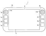
- FIG. 2A is a front view of an external appearance centering on a display unit of the vehicle navigation device
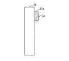
- FIG. 2B is a side view of the appearance centering on the display unit of the vehicle navigation device
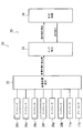
- FIG. 3 is a block diagram showing a schematic configuration of the touch detection device
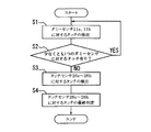
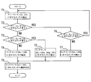
- FIG. 4 is a flowchart showing the contents of processing by the touch detection device
- FIG. 5 is a flowchart showing the contents of processing by the touch detection device of the second embodiment.
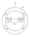
- FIG. 6 is an external front view of the steering wheel of the fourth embodiment.
- FIG. 7 is a block diagram illustrating a schematic configuration of the touch detection device according to the fourth embodiment.
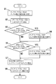
- FIG. 8 is a flowchart illustrating the contents of the process performed by the touch detection device according to the fourth embodiment.
- a vehicular navigation device 1 has a position detector 3, an external memory 4, a key position detector 5, a map data input to a control circuit 2 having a function of controlling the overall operation of the device.
- voice output apparatus 9, etc. are connected.
- the control circuit 2 is mainly composed of a microcomputer, and includes a CPU, a ROM, an AM, an I / O, and a bus for connecting them (not shown).
- the ROM stores a control program for operating the car navigation device
- the RAM temporarily stores processing data when the program is executed, map data acquired from the map data input device 6, and the like.
- the position detector 3 receives a GPS signal from a GPS (Global Positioning System) satellite and detects a position of the vehicle, a GPS receiver 3a, a gyroscope 3b that detects the traveling direction of the vehicle, and a vehicle speed in the front-rear direction.
- a vehicle speed sensor 3c for detecting the vehicle a geomagnetic sensor 3d for detecting the traveling direction of the vehicle, and the like. Since each of these sensors has an error based on its inherent property, each sensor is used while interpolating each other's output results.
- the position detector 3 may be constituted by only a part of these, and further, a rotation sensor for detecting the steering angle of the steering, or a wheel sensor disposed on each rolling wheel. Etc. may be added.
- the external memory 4 is composed of, for example, a flash memory card, and is provided, for example, for storing or calling specific data such as point registration data, music data, and video data.
- the key position detection unit 5 detects the key position (key position) of an ignition switch (not shown) of an automobile (vehicle) on which the vehicle navigation device 1 is mounted, that is, turns the engine on / off, that is, power Has a function of detecting ON / OFF of the.
- the map data is input via a map data input device 6 for inputting various data including map data.
- the storage medium of the map data input device 6 is generally a CD-ROM, DVD, hard disk or the like because of its data amount, but may be another medium such as a memory card.
- the display unit 8 includes, for example, a color liquid crystal display for displaying a map, characters, and the like, and is installed near the driver's seat of the vehicle.
- a marker indicating the current position of the vehicle input from the position detector 3 map data input via the map data input device 6, and guidance routes and settings displayed on the map are further displayed. Additional data such as a place mark is superimposed and displayed.
- various input screens for searching and inputting a destination by the user, various messages and information, and the like are also displayed.
- the vehicle navigation device 1 notifies the driver of the driving guidance by voice through the voice output device 9 and gives the driving guidance to the driver by both the display by the display unit 8 and the voice output by the voice output device 9. .
- the input operation unit 7 is disposed integrally with the display unit 8 and is, for example, a touch panel 7i using a resistive film system, a front surface portion of the main body 10, and a display unit.
- 8 includes switches 7a to 7h arranged around (right and left) and is used for various inputs.
- the switches 7a and 7b are mechanical switches (hard switches) and are operation knobs capable of both rotating operation and pressing operation.
- the switches 7a and 7b are also referred to as operation knobs 7a and 7b.
- the switches 7c to 7h are configurations using capacitive touch sensors, that is, touch switches.
- Dummy sensors 11a and 11b are provided on the operation knobs 7a and 7b, respectively.
- the dummy sensors 11a and 11b use capacitive touch sensors. Although detailed illustration is omitted, the dummy sensors 11a and 11b are located at locations where capacitive coupling can be performed between the dummy fingers 11a and 11b and the fingers when the fingers touch the operation knobs 7a and 7b (see FIG. 2A). (Hatching location in FIG. 2B).
- the dummy sensors 11a and 11b are in positions that do not overlap with the switches 7c to 7h, when the user's fingers or the like approach the operation knobs 7a and 7b, the dummy sensors 11a and 11b can perform capacitive coupling with the fingers. You may arrange
- the dummy sensors 11a and 11b are not provided for the purpose of performing a desired operation, but are provided for the purpose of preventing malfunction in the input operation unit 7.
- touch switches may also be arranged above and below the display unit 8.
- a remote controller (not shown) having functions equivalent to those of the operators 7a to 7i is also provided, and an operation signal from the remote controller is given to the control circuit 2 through the remote controller sensor 7j.
- the touch operation on the switches 7c to 7h and the dummy sensors 11a and 11b, that is, the touch on the touch sensor is detected by the touch detection device 21 shown in FIG. In FIG. 1, illustration of the touch detection device 21 is omitted. A detection result by the touch detection device 21 is given to the control circuit 2.
- the touch detection device 21 includes a capacitance detection unit 22 (corresponding to a capacitance detection unit), a touch detection unit 23, and a determination control unit 24.
- the touch detection unit 23 and the determination control unit 24 constitute a touch determination unit 25.
- the capacitance detector 22 detects the capacitance values of the touch sensors 26c to 26h corresponding to the switches 7c to 7h, respectively. In addition, the capacitance detection unit 22 also detects the capacitance values of the dummy sensors 11a and 11b. The detection values of the capacitances of the touch sensors 26c to 26h and the dummy sensors 11a and 11b detected by the capacitance detection unit 22 are given to the touch detection unit 23.
- the touch detection unit 23 determines the presence / absence of a touch on the touch sensors 26c to 26h (and thus a touch operation on the switches 7c to 7h) based on the detection value of the capacitance given from the capacitance detection unit 22. In addition, the touch detection unit 23 determines the presence or absence of a touch on the dummy sensors 11a and 11b (and an operation on the operation knobs 7a and 7b) based on the detected capacitance value provided from the capacitance detection unit 22. In this case, when the amount of change in capacitance of the touch sensors 26c to 26h or the dummy sensors 11a and 11b exceeds a predetermined determination value, the touch detection unit 23 determines that there is a touch on the sensor. When the instruction to execute the process is given from the determination control unit 24, the touch detection unit 23 executes the process for determining the presence or absence of the touch described above.
- the touch detection unit 23 outputs information (operation detection information) regarding the presence or absence of touch to the touch sensors 26c to 26h and the dummy sensors 11a and 11b to the determination control unit 24.
- the determination control unit 24 instructs the touch detection unit 23 to determine the presence / absence of a touch every predetermined cycle (for example, 1/1000 second). Based on the operation detection information given from the touch detection unit 23, the determination control unit 24 finally determines whether or not there is a touch on the touch sensors 26c to 26h.
- the result of the final determination by the determination control unit 24 is given to the control circuit 2 as the operation result of the touch sensors 26c to 26h, that is, the switches 7c to 7h.
- the determination control unit 24 instructs the touch detection unit 23 to execute processing for determining whether or not the dummy sensors 11a and 11b are touched (step S1). And the determination control part 24 judges the presence or absence of the touch with respect to the dummy sensors 11a and 11b based on the operation detection information given from the touch detection part 23 (step S2).
- step S2 If it is determined that there is a touch on at least one of the dummy sensors 11a and 11b (S2: YES), the process returns to step S1. On the other hand, when it is determined that there is no touch on either of the dummy sensors 11a and 11b (S2: NO), the process proceeds to step S3. In step S3, the determination control unit 24 instructs the touch detection unit 23 to execute processing for determining whether or not the touch sensors 26c to 26h are touched. Then, the determination control unit 24 finally determines whether or not the touch sensors 26c to 26h are touched based on the operation detection information given from the touch detection unit 23 (step S4).
- the determination control unit 24 first determines whether or not the dummy sensors 11a and 11b are touched. When the determination control unit 24 determines that there is a touch on one or both of the dummy sensors 11a and 11b, the determination control unit 24 does not determine whether or not the touch sensors 26c to 26h are touched (invalidate). Therefore, when the operation knob 7a adjacent to the switch 7c or the operation knob 7b adjacent to the switch 7f is operated, the occurrence of malfunction due to unintended contact by the user is prevented as follows.
- the capacitance of the dummy sensor 11a or 11b changes.
- the amount of change in capacitance of the dummy sensors 11a and 11b exceeds the determination value, it is not determined whether or not the touch sensors 26c to 26h are touched. Therefore, during the period in which the user operates the operation knob 7a or 7b, the operation determination on the switches 7c and 7f is not performed. Therefore, when operating the operation knob 7a or 7b, even if the user's finger accidentally touches the switch 7c or 7f, an unintended malfunction does not occur.
- the occurrence of malfunction due to external radio noise can be prevented as follows. That is, in an environment where external radio noise occurs, the capacitances of the touch sensors 26c to 26h and the dummy sensors 11a and 11b change similarly. If the determination control unit 24 determines that there is a touch on one or both of the dummy sensors 11a and 11b, the determination control unit 24 does not determine whether or not the touch sensors 26c to 26h are touched. That is, when the amount of change in the capacitance of one or both of the dummy sensors 11a and 11b exceeds the determination value, the determination as to whether or not the touch sensors 26c to 26h are touched is not performed.
- the determination control unit 24 instructs the touch detection unit 23 to execute processing for determining whether or not the dummy sensors 11a and 11b are touched (step T1). And the determination control part 24 judges the presence or absence of the touch with respect to the dummy sensor 11a based on the operation detection information given from the touch detection part 23 (step T2). If it is determined that there is no touch on the dummy sensor 11a (T2: NO), the process proceeds to step T3.
- step T3 the determination control unit 24 determines whether or not the dummy sensor 11b is touched based on the operation detection information. If it is determined that there is no touch on the dummy sensor 11b (T3: NO), that is, if it is determined that there is no touch on either of the dummy sensors 11a and 11b, the process proceeds to step T4. In step T4, the determination control unit 24 instructs the touch detection unit 23 to execute processing for determining whether or not the touch sensors 26c to 26h are touched.
- step T3 If it is determined in step T3 that the dummy sensor 11b is touched (YES), the process proceeds to step T5.
- step T5 the determination control unit 24 instructs the touch detection unit 23 to execute processing for determining whether or not the touch sensors 26c to 26e, 26g, and 26h are touched.
- step T2 when it is determined in step T2 that there is a touch on the dummy sensor 11a (T2: YES), the process proceeds to step T6.
- step T6 whether or not the dummy sensor 11b is touched is determined in the same manner as in step T3. If it is determined that there is a touch on the dummy sensor 11b (YES), that is, if it is determined that both the dummy sensors 11a and 11b have a touch, the process returns to step T1.
- step T6 If it is determined in step T6 that there is no touch on the dummy sensor 11b (NO), the process proceeds to step T7.
- step T7 the determination control unit 24 instructs the touch detection unit 23 to execute processing for determining whether or not the touch sensors 26d to 26h are touched.
- step T8 the determination control unit 24 finally determines whether or not the touch sensors 26c to 26h are touched based on the operation detection information given from the touch detection unit 23.
- the determination control unit 24 of the present embodiment individually determines the presence or absence of a touch on the two dummy sensors 11a and 11b.
- the determination control unit 24 determines whether or not there is a touch on the touch sensor 26c provided in the vicinity of the dummy sensor 11a. No (disable). For this reason, when the operation knob 7a adjacent to the switch 7c is operated, the occurrence of malfunction due to unintended contact by the user is prevented as in the first embodiment.
- the presence / absence of the touch on the touch sensors 26d to 26h is determined, it is possible to deal with a case of “operating a touch switch other than the switch 7c while operating the operation knob 7a”.
- the determination control unit 24 determines whether or not the touch sensor 26f provided near the dummy sensor 11b is touched. No (disable). Therefore, when the operation knob 7b adjacent to the switch 7f is operated, the occurrence of malfunction due to unintended contact by the user is prevented as in the first embodiment. In addition, in this case, since it is determined whether or not the touch sensors 26c to 26e, 26g, and 26h are touched, it corresponds to a case of “operating a touch switch other than the switch 7f while operating the operation knob 7b”. it can.
- the determination control unit 24 of this embodiment determines that there is a touch on both the dummy sensors 11a and 11b, the determination control unit 24 does not determine whether or not there is a touch on all the touch sensors 26c to 26h. Therefore, the occurrence of malfunction due to external radio noise is also prevented as in the first embodiment. Therefore, according to the present embodiment, the same effect as that of the first embodiment can be obtained, and an excellent effect that it is possible to cope with various operation methods by the user can be obtained.
- the determination values for determining whether or not the touch sensors 26c to 26h and the dummy sensors 11a and 11b are touched are the same fixed value. That is, in each of the above embodiments, the touch sensors 26c to 26h and the dummy sensors 11a and 11b are detected with the same detection sensitivity. However, the touch sensors 26c to 26h and the dummy sensors 11a and 11b may be changed to detect touches with different detection sensitivities. As an example of such a change, it can be considered that the detection sensitivities of the dummy sensors 11a and 11b are dynamically changed according to various conditions with respect to the detection sensitivities of the touch sensors 26c to 26h.
- a description will be given of a third embodiment in which such changes are made to the above embodiments.
- the determination values of the dummy sensors 11a and 11b are set to normal values when the vehicle is stopped, and are set to values lower than normal when the vehicle is traveling. That is, when the vehicle is running, the detection sensitivity of the dummy sensors 11a and 11b is increased (weighted) relative to the detection sensitivity of the touch sensors 26c to 26h.
- the normal determination value of the dummy sensors 11a and 11b is the capacitance of the dummy sensor 11a or 11b when the vehicle is stopped and the user's finger contacts (or approaches) the operation knob 7a or 7b. Is the amount of change.
- the operation knobs 7a and 7b are assigned functions that cannot be used (disabled) during traveling, such as destination setting and audio source switching functions, the operation knobs 7a and 7b are used as vehicles. It is not operated while driving. In such a case, the function of the dummy sensors 11a and 11b arranged on the operation knobs 7a and 7b (function to prevent malfunction caused by the user's fingers not touching the switches 7c and 7f unintentionally) is invalidated. Also good.
- the determination value of the dummy sensor 11a corresponding to the operation knob 7a is set to a value higher than normal (usually considered static). Set to a value larger than the maximum value of the change in capacitance). That is, when the vehicle is traveling, the detection sensitivity of the dummy sensor corresponding to the operation unit assigned with the function not used during traveling is lowered (weighted) with respect to the detection sensitivity of the touch sensors 26c to 26h. In this way, when the switch 7c is operated, even if the user's finger accidentally touches the operation knob 7a located in the vicinity thereof, the determination of whether or not the switch 7c is touched is invalidated. None will happen.
- the detection sensitivity of the dummy sensor is set as follows (a) and (b) based on the relationship between the function assigned to the operation knobs 7a and 7b and the function executed immediately before. Can be changed.
- an audio volume adjustment function is assigned to the operation knob 7b
- a current position display return function (current position switch) is assigned to the switch 7f located in the vicinity of the operation knob 7b.
- the audio screen is a screen for selecting a sound source (source) such as a radio or a CD.
- a sound source such as a radio or a CD.
- the volume of audio playback is often different depending on the sound source. Therefore, when an audio screen is displayed on the display unit 8 by performing an operation related to the audio screen immediately before, there is a high possibility that the user will operate the operation knob 7b thereafter.
- the operation knob 7b has, for example, a volume adjustment function.
- the possibility that the user operates the switch 7f is low.
- the switch 7f has, for example, a current location return function.
- the judgment value of the dummy sensor 11b corresponding to the operation knob 7b is set to a value lower than usual. That is, when the relationship between the function assigned to the operation knob 7b and the function executed immediately before is high, the detection sensitivity of the dummy sensor 11b is increased. In this way, it is easy to determine that there is a touch on the dummy sensor 11b. Therefore, when the operation on the operation knob 7b that is highly likely to be operated is performed, the switch 7f that is unlikely to be operated is not intended. It is possible to reliably prevent the occurrence of a malfunction that is determined to be performed.
- the determination value of the dummy sensor 11b corresponding to the operation knob 7b is set to a higher value than usual. That is, when the relationship between the function assigned to the operation knob 7b and the function executed immediately before is low, the detection sensitivity of the dummy sensor 11b is lowered. In this way, it is easy to determine that there is no touch on the dummy sensor 11b. Therefore, when the switch 7f, which is highly likely to be operated, is operated, the user's fingers are less likely to be operated. Even if the user touches the switch 7b by mistake, the determination of whether or not the switch 7f is touched is not invalidated.
- the detection sensitivities of the dummy sensors 11a and 11b are dynamically changed according to various conditions with respect to the detection sensitivities of the touch sensors 26c to 26h. Accordingly, it is possible to accurately prevent a malfunction that dynamically changes depending on the situation (contact in the operation knobs 7a and 7b causes malfunction in some situations, but contact in the switches 7c and 7f causes malfunction in other situations). The effect that it can be obtained.
- Steering switches 32a to 32d to which various functions (air conditioner temperature adjustment function, audio volume adjustment function, etc.) are assigned, are provided on the surface (driver side surface) of the spoke portion 31a of the steering wheel 31. ing.
- the steering switches 32a to 32d are configurations using capacitive touch sensors, that is, touch switches.
- Dummy sensors 33a to 33d are provided on the back surface (the surface opposite to the driver) of the grip portion 31b of the steering wheel 31.
- the dummy sensors 33a to 33d use capacitive touch sensors.
- the dummy sensors 33a to 33d are arranged at locations where capacitive coupling can be performed with the fingers when the user grips the grip portion 31b to operate the steering wheel 31.
- the positions of the dummy sensors 33a to 33d are positions that do not overlap with the steering switches 32a to 32d, and when the user holds the steering wheel 31, capacitive coupling can be performed with the fingers. If it is a position, it can change suitably.
- the dummy sensors 33a to 33d are not provided for the purpose of performing a desired operation, but are provided for the purpose of preventing malfunction of the steering switches 32a to 32d.
- the touch operation on the steering switches 32a to 32d and the dummy sensors 33a to 33d is detected by the touch detection device 34 shown in FIG.
- the touch detection device 34 has the same configuration as the touch detection device 21 shown in FIG. In this case, the capacitance detector 22 detects the capacitance values of the touch sensors 35a to 35d corresponding to the steering switches 32a to 32d and the capacitance values of the dummy sensors 33a to 33d.
- the determination control unit 24 sets all of the touch sensors 35a to 35d as touch determination targets (step U1). Subsequently, the determination control unit 24 instructs the touch detection unit 23 to execute processing for determining whether or not the dummy sensors 33a to 33d are touched (step U2). And the determination control part 24 judges the presence or absence of the touch with respect to the dummy sensors 33a and 33b based on the operation detection information given from the touch detection part 23 (step U3).
- Step U4 the touch sensors 35a and 35b arranged on the same side as the dummy sensors 33a and 33b (left side toward the front of the vehicle) are excluded from the determination targets of the presence or absence of touch. After execution of step U4, the process proceeds to step U5. On the other hand, if it is determined that neither of the dummy sensors 33a and 33b is touched (U3: NO), the process proceeds to step U5 as it is.
- Step U5 the determination control unit 24 determines whether or not the dummy sensors 33c and 33d are touched based on the operation detection information given from the touch detection unit 23.
- the process proceeds to step U6.
- step U6 the touch sensors 35c and 35d arranged on the same side as the dummy sensors 33c and 33d (on the right side toward the front of the vehicle) are excluded from the determination targets of the presence or absence of touch. After execution of step U6, the process proceeds to step U7.
- step U7 the determination control unit 24 instructs the touch detection unit 23 to execute a process for determining whether or not there is a touch on the sensor set as the determination target among the touch sensors 35a to 35d. Then, the determination control unit 24 finally determines whether or not the touch sensors 35a to 35d are touched based on the operation detection information given from the touch detection unit 23 (step U8).
- the dummy sensors 33a to 33b are touched.
- the touch sensors 35a and 35b arranged on the left side of the spoke portion 31a are touched.
- the touch sensors 35c and 35d arranged on the right side of the spoke portion 31a are touched. I will not. Therefore, when the steering wheel 31 is operated, the occurrence of malfunction due to unintended contact by the user is prevented as follows.
- the occurrence of malfunction due to external radio noise can be prevented as follows. That is, in an environment where external radio noise has occurred, the capacitances of the touch sensors 35a to 35d and the dummy sensors 33a to 33d change in the same manner. In the present embodiment, if it is determined that all the dummy sensors 33a to 33d are touched, it is not determined whether or not all the touch sensors 35a to 35d are touched. In other words, when the amount of change in capacitance of all the dummy sensors 33a to 33d exceeds the determination value, it is not determined whether or not there is a touch on all the touch sensors 35a to 35d.
- the touch panel 7i of the vehicle navigation device 1 may use a capacitive touch switch (touch sensor).
- the touch switch of the touch panel 7i may be handled in the same manner as the touch switches (7c, 7f) existing in the vicinity of the operation knobs 7a, 7b, and the same processing as in the first to third embodiments may be applied.
- the switches 7c to 7h are not limited to a configuration in which one touch sensor is provided for one switch, and may be a configuration in which a plurality of touch sensors are provided for one switch.
- the operation knobs 7a and 7b, the switches 7c to 7h, and the steering switches 32a to 32d are not limited to the configuration in which a predetermined fixed function is assigned, and the assigned functions can be arbitrarily switched. Also good. In that case, the detection sensitivity of the dummy sensor may be changed according to the assigned function.
- the touch detection devices 21 and 34 can be used not only for the applications described in the above embodiments (in-vehicle applications) but also for general applications for detecting a touch on a capacitive touch sensor.
- an operation unit structural operation unit, mechanical switch, electrical switch, etc.
- the user does not intend.
- production of the malfunction by contact can be prevented effectively.
- Near here means a distance that allows the user to touch the touch sensor and the dummy sensor at the same time. In other words, it means that the touch sensor and the dummy sensor have such a distance that the other sensor can be capacitively coupled with the user's finger by touching (contacting or approaching) one of the sensors.
- the touch detection operation (the flowchart in FIG. 4) in the first embodiment can be applied to both the case where there is only one operation unit and a dummy sensor and the case where there are a plurality of dummy sensors.
- the touch detection operation (the flowchart of FIG. 5) in the second embodiment can be applied not only when there are two operation units (and dummy sensors) described above, but also when there are three or more.
- the touch detection device detects a touch on a capacitive touch sensor that is touch-operated by a user as follows. That is, when the user's finger touches the touch sensor, the capacitance value of the touch sensor changes.
- the touch determination unit detects such a change in capacitance based on the detection value of the capacitance detection unit that detects the capacitance value of the touch sensor, thereby determining the presence or absence of a touch.
- an operation unit operated by the user is disposed in the vicinity of the touch sensor.
- the possibility that the finger touches the touch sensor by mistake is relatively high. Therefore, there is a possibility that a malfunction that is not intended by the user may occur. Therefore, the headquarters prevents the occurrence of the malfunction as follows.
- a capacitive dummy sensor is arranged in the operation unit.
- the capacitance detection unit also detects the capacitance value of the dummy sensor.
- the touch determination unit detects that the capacitance change amount of the dummy sensor exceeds a predetermined determination value based on the detection value of the capacitance detection unit, the touch determination unit invalidates the determination of whether or not the touch sensor is touched.
- the capacitance of the dummy sensor changes. And if the variation
- the occurrence of malfunction due to external radio noise can be prevented as follows.
- the capacitances of the touch sensor and the dummy sensor change in the same manner.
- a touch determination part invalidates determination of the presence or absence of the touch with respect to a touch sensor, when the variation
- change_quantity of the electrostatic capacitance of a dummy sensor exceeds determination value.
Landscapes
- Engineering & Computer Science (AREA)
- General Engineering & Computer Science (AREA)
- Theoretical Computer Science (AREA)
- Human Computer Interaction (AREA)
- Physics & Mathematics (AREA)
- General Physics & Mathematics (AREA)
- Mechanical Engineering (AREA)
- Transportation (AREA)
- Chemical & Material Sciences (AREA)
- Combustion & Propulsion (AREA)
- Switches That Are Operated By Magnetic Or Electric Fields (AREA)
- Position Input By Displaying (AREA)
- User Interface Of Digital Computer (AREA)
Abstract
Description
以下、第1の実施形態について図1~図4を参照しながら説明する。
第1の実施形態では、ダミーセンサ11a、11bのうち少なくとも一方に対するタッチが有ると判断された場合、全てのタッチセンサ26c~26hに対するタッチの有無の判定が無効にされていた。このようにすれば、処理が簡素化できるというメリットがある。一方で、「操作ノブ7aを操作しながらスイッチ7c以外のタッチスイッチを操作する」または「操作ノブ7bを操作しながらスイッチ7f以外のタッチスイッチを操作する」という稀なケースに対応することができない。以下、このようなケースに対応することができるように、タッチセンサに対するタッチの検出動作を変更した第2の実施形態について、図5を参照しながら説明する。
上記各実施形態では、タッチセンサ26c~26hと、ダミーセンサ11a、11bとのそれぞれに対するタッチの有無を判定するための判定値は同一の固定値であった。すなわち、上記各実施形態では、タッチセンサ26c~26hと、ダミーセンサ11a、11bとについて、同一の検出感度でもって、そのタッチを検出していた。しかし、タッチセンサ26c~26hと、ダミーセンサ11a、11bとについて、互いに別々の検出感度でもって、そのタッチを検出するように変更してもよい。このような変更の一例として、ダミーセンサ11a、11bの検出感度を、タッチセンサ26c~26hの検出感度に対し、各種の条件に応じて動的に変化させるということが考えられる。以下、上記各実施形態に対し、このような変更を加えた第3の実施形態について説明する。
車両用ナビゲーション装置1が搭載された車両が走行しているときには、それに伴う振動により、ユーザの手元がおぼつかない可能性がある。そのため、車両の走行中には、ユーザの手指の意図しない接触による誤動作が発生し易い。そこで、ダミーセンサ11a、11bの判定値を、車両が停車中であるときには通常の値に設定するとともに、車両が走行中であるときには通常よりも低い値に設定する。つまり、車両が走行中であるとき、タッチセンサ26c~26hの検出感度に対し、ダミーセンサ11a、11bの検出感度を高くする(重み付けを行う)。
操作ノブ7a、7bに対し、例えば目的地設定やオーディオソースの切替機能など、走行中に使用不可能となる(無効化される)機能が割り付けられている場合、その操作ノブ7a、7bが車両の走行中に操作されることはない。このような場合、操作ノブ7a、7bに配置されたダミーセンサ11a、11bの機能(ユーザの手指が意図せずにスイッチ7c、7fに接触することで生じる誤動作を防止する機能)を無効化してもよい。
操作ノブ7a、7bに割り付けられた機能と、直前に実行された機能(操作)との関連性が高い場合、その後にユーザが操作ノブ7a、7bの操作を行う可能性が高い。これに対し、操作ノブ7a、7bに割り付けられた機能と、直前に実行された機能との関連性が低い、または関連性が無い場合、その後にユーザが操作ノブ7a、7bの操作を行う可能性は低い。
オーディオ画面とは、ラジオ、CDなどの音源(ソース)を選択する画面である。一般に、オーディオを再生する際の音量は、その音源により互いに異なることが多い。従って、直前にオーディオ画面に関する操作が行われることによって表示部8にオーディオ画面が表示されている場合、その後にユーザが操作ノブ7bを操作する可能性が高い。なお、操作ノブ7bは、例えば、音量調整機能を備える。一方、この場合、ユーザがスイッチ7fを操作する可能性は低い。スイッチ7fは、例えば、現在地復帰機能を備える。
直前に地図に関する操作が行われることによって表示部8に地図画面(特に、スクロールされた地図画面)が表示されている場合、その後にユーザがスイッチ7fを操作する(現在地復帰機能が使用される)可能性が高い。一方、この場合、ユーザが操作ノブ7bを操作する(音量調整機能が使用される)可能性は低い。
以下、本開示の第4の実施形態について図6~図8を参照しながら説明する。
なお、本開示は上記し且つ図面に記載した各実施形態に限定されるものではなく、次のような変形または拡張が可能である。
Claims (7)
- ユーザによりタッチ操作される静電容量方式のタッチセンサ(26c~26h、35a~35d)に対するタッチを検出するタッチ検出装置(21、34)であって、
前記タッチセンサ(26c~26h、35a~35d)の近傍に設けられユーザにより操作される操作部(7a、7b、31)に配置された静電容量方式のダミーセンサ(11a、11b、33a~33d)と、
前記タッチセンサ(26c~26h、35a~35d)および前記ダミーセンサ(11a、11b、33a~33d)の静電容量の値を検出する静電容量検出部(22)と、
前記静電容量検出部(22)の検出値に基づいて前記タッチセンサ(26c~26h、35a~35d)に対するタッチの有無を判定するタッチ判定部(25)と、
を備え、
前記タッチ判定部(25)は、前記ダミーセンサ(11a、11b、33a~33d)の静電容量の変化量が所定の判定値を超えると、前記タッチセンサ(26c~26h、35a~35d)に対するタッチの有無の判定を無効にするタッチ検出装置。 - 複数の前記タッチセンサ(26c~26h、35a~35d)に対応するように複数の前記ダミーセンサ(11a、11b、33a~33d)が設けられる場合、
前記タッチ判定部(25)は、所定の前記ダミーセンサ(11a、11b、33a~33d)の静電容量の変化量が前記判定値を超えると、そのダミーセンサ(11a、11b、33a~33d)の近傍に設けられた前記タッチセンサ(26c~26h、35a~35d)に対するタッチの有無の判定を無効にする請求項1に記載のタッチ検出装置。 - 前記タッチ判定部(25)は、複数の前記ダミーセンサ(11a、11b、33a~33d)の静電容量の変化量がいずれも前記判定値を超えると、全ての前記タッチセンサ(26c~26h、35a~35d)に対するタッチの有無の判定を無効にする請求項2に記載のタッチ検出装置。
- 前記タッチ判定部(25)は、前記操作部(7a、7b)に対する操作が行われる可能性が高い場合には前記判定値を通常よりも低い値に設定し、前記操作部(7a、7b)に対する操作が行われる可能性が低い場合には前記判定値を通常よりも高い値に設定する請求項1から3のいずれか一項に記載のタッチ検出装置。
- 前記タッチセンサ(26c~26h、35a~35d)および前記ダミーセンサ(11a、11b、33a~33d)は、車両に設けられており、
前記タッチ判定部(25)は、前記車両が走行中であるときには前記判定値を通常よりも低い値に設定する請求項1から4のいずれか一項に記載のタッチ検出装置。 - 静電容量方式のタッチセンサを用いたスイッチ(7c~7h)と、
請求項1から5のいずれか一項に記載のタッチ検出装置(21)と、
を備えた車両用ナビゲーション装置(1)であって、
前記ダミーセンサ(11a、11b)が配置される前記操作部(7a、7b)は、前記スイッチ(7c~7h)の近傍に設けられユーザにより操作される操作ノブ(7a、7b)であり、
前記タッチ検出装置(21)を用いて前記スイッチ(7c~7h)に対するタッチ操作を検出する車両用ナビゲーション装置。 - 前記タッチ判定部(25)は、前記操作部(7a、7b)に割り付けられた機能と、前記操作部(7a、7b)の操作の直前に実行された機能との間に関連性がある場合を、前記操作部(7a、7b)に対する操作が行われる可能性が高いとみなし、前記判定値を低下させ、
前記操作部(7a、7b)に割り付けられた機能と、前記操作部(7a、7b)の操作の直前に実行された機能とに関連性がない場合を、前記操作部(7a、7b)に対する操作が行われる可能性が低いとみなし、前記判定値を上昇させる請求項1から3のいずれか一項に記載のタッチ検出装置。
Priority Applications (3)
| Application Number | Priority Date | Filing Date | Title |
|---|---|---|---|
| DE112014004094.0T DE112014004094T5 (de) | 2013-09-05 | 2014-09-01 | Berührungserfassungsvorrichtung und Fahrzeugnavigationsvorrichtung |
| CN201480048671.3A CN105556632B (zh) | 2013-09-05 | 2014-09-01 | 触摸检测装置以及车辆用导航装置 |
| US14/916,199 US10365772B2 (en) | 2013-09-05 | 2014-09-01 | Touch detection apparatus and vehicle navigation apparatus |
Applications Claiming Priority (2)
| Application Number | Priority Date | Filing Date | Title |
|---|---|---|---|
| JP2013-183979 | 2013-09-05 | ||
| JP2013183979A JP6123590B2 (ja) | 2013-09-05 | 2013-09-05 | タッチ検出装置および車両用ナビゲーション装置 |
Publications (1)
| Publication Number | Publication Date |
|---|---|
| WO2015033544A1 true WO2015033544A1 (ja) | 2015-03-12 |
Family
ID=52628044
Family Applications (1)
| Application Number | Title | Priority Date | Filing Date |
|---|---|---|---|
| PCT/JP2014/004461 Ceased WO2015033544A1 (ja) | 2013-09-05 | 2014-09-01 | タッチ検出装置および車両用ナビゲーション装置 |
Country Status (5)
| Country | Link |
|---|---|
| US (1) | US10365772B2 (ja) |
| JP (1) | JP6123590B2 (ja) |
| CN (1) | CN105556632B (ja) |
| DE (1) | DE112014004094T5 (ja) |
| WO (1) | WO2015033544A1 (ja) |
Cited By (1)
| Publication number | Priority date | Publication date | Assignee | Title |
|---|---|---|---|---|
| JP2018125224A (ja) * | 2017-02-03 | 2018-08-09 | アール・ビー・コントロールズ株式会社 | 操作装置 |
Families Citing this family (12)
| Publication number | Priority date | Publication date | Assignee | Title |
|---|---|---|---|---|
| JPH0617387Y2 (ja) | 1987-06-25 | 1994-05-02 | ソニー株式会社 | タイムコ−ド信号読取装置 |
| US9800242B1 (en) * | 2016-04-14 | 2017-10-24 | Panasonic Intellectual Property Management Co., Ltd. | Operation switch, dressing table and mirror using capacitance sensor |
| CN107390935B (zh) * | 2017-07-31 | 2020-07-28 | 惠州市德赛西威汽车电子股份有限公司 | 一种触控面板防误触的方法 |
| KR102354135B1 (ko) * | 2017-10-12 | 2022-01-24 | 현대자동차주식회사 | 근접센서 |
| JP6982310B2 (ja) * | 2018-01-11 | 2021-12-17 | 東京パーツ工業株式会社 | 静電容量センサ |
| JP2020008990A (ja) * | 2018-07-04 | 2020-01-16 | 富士通コンポーネント株式会社 | スイッチシステム |
| EP4628389A3 (en) * | 2019-03-25 | 2025-12-10 | Alps Alpine Co., Ltd. | Sensor device and steering wheel |
| JP7402749B2 (ja) * | 2020-06-01 | 2023-12-21 | 株式会社東海理化電機製作所 | 静電センサ、制御装置、およびコンピュータプログラム |
| JP7222960B2 (ja) | 2020-10-27 | 2023-02-15 | 株式会社ホンダアクセス | タッチパネル装置 |
| EP4407417A4 (en) | 2022-01-26 | 2025-03-05 | Samsung Electronics Co., Ltd. | Wireless power transmitting apparatus including user interface and method for determining whether touch input of wireless power transmitting apparatus has occurred |
| CN118647540A (zh) * | 2022-02-09 | 2024-09-13 | 奥托立夫开发公司 | 乘员状态检测装置及计算机程序 |
| WO2025046945A1 (ja) * | 2023-08-31 | 2025-03-06 | アルプスアルパイン株式会社 | センサ装置 |
Citations (4)
| Publication number | Priority date | Publication date | Assignee | Title |
|---|---|---|---|---|
| JP2009213126A (ja) * | 2008-02-08 | 2009-09-17 | Rohm Co Ltd | 静電センサを用いたリモートコントロール装置および電子機器、ならびにスイッチの制御方法 |
| JP2010141834A (ja) * | 2008-12-15 | 2010-06-24 | Toto Ltd | 操作入力装置及び吐水装置 |
| JP2012243566A (ja) * | 2011-05-19 | 2012-12-10 | Tokai Rika Co Ltd | 車両用スイッチ装置 |
| JP2012247839A (ja) * | 2011-05-25 | 2012-12-13 | Sanyo Electric Co Ltd | 電子機器 |
Family Cites Families (16)
| Publication number | Priority date | Publication date | Assignee | Title |
|---|---|---|---|---|
| US6424338B1 (en) * | 1999-09-30 | 2002-07-23 | Gateway, Inc. | Speed zone touchpad |
| US7606358B2 (en) * | 1999-10-08 | 2009-10-20 | Mcgary Faith | System and method for providing personal directory assistance services |
| US7289354B2 (en) * | 2005-07-28 | 2007-10-30 | Texas Instruments Incorporated | Memory array with a delayed wordline boost |
| DE202005019978U1 (de) * | 2005-10-12 | 2006-04-20 | E.G.O. Elektro-Gerätebau GmbH | Bedienvorrichtung für ein Elektrogerät |
| US20080008858A1 (en) * | 2006-07-08 | 2008-01-10 | Hong Keith C | Roofing Products Containing Phase Change Materials |
| US8274479B2 (en) * | 2006-10-11 | 2012-09-25 | Apple Inc. | Gimballed scroll wheel |
| JP4302728B2 (ja) | 2006-12-06 | 2009-07-29 | 小島プレス工業株式会社 | 車両アクセサリ用タッチスイッチ |
| JP2008197934A (ja) * | 2007-02-14 | 2008-08-28 | Calsonic Kansei Corp | 操作者判別方法 |
| KR101442542B1 (ko) * | 2007-08-28 | 2014-09-19 | 엘지전자 주식회사 | 입력장치 및 이를 구비한 휴대 단말기 |
| US8421757B2 (en) * | 2007-10-12 | 2013-04-16 | Sony Corporation | Touch sensor with a plurality of touch sensor sections |
| JP2010020674A (ja) | 2008-07-14 | 2010-01-28 | Tokai Rika Co Ltd | タッチセンサ装置 |
| CN201312300Y (zh) * | 2008-09-23 | 2009-09-16 | 上海科世达-华阳汽车电器有限公司 | 一种触摸感应式汽车开关 |
| DK2508316T3 (en) * | 2011-04-08 | 2015-01-12 | Saint Gobain Placo Sas | Process for making gypsum products |
| US9854209B2 (en) * | 2011-04-19 | 2017-12-26 | Ford Global Technologies, Llc | Display system utilizing vehicle and trailer dynamics |
| GB2506676B (en) * | 2012-10-08 | 2015-03-25 | Touchnetix Ltd | Touch sensors and touch sensing methods |
| KR102047865B1 (ko) * | 2013-01-04 | 2020-01-22 | 삼성전자주식회사 | 터치 키 입력 유효성을 판별하는 단말 장치와 이에 이용되는 터치 키 입력 유효성 판별 방법 및 장치 |
-
2013
- 2013-09-05 JP JP2013183979A patent/JP6123590B2/ja active Active
-
2014
- 2014-09-01 DE DE112014004094.0T patent/DE112014004094T5/de not_active Withdrawn
- 2014-09-01 US US14/916,199 patent/US10365772B2/en active Active
- 2014-09-01 CN CN201480048671.3A patent/CN105556632B/zh not_active Expired - Fee Related
- 2014-09-01 WO PCT/JP2014/004461 patent/WO2015033544A1/ja not_active Ceased
Patent Citations (4)
| Publication number | Priority date | Publication date | Assignee | Title |
|---|---|---|---|---|
| JP2009213126A (ja) * | 2008-02-08 | 2009-09-17 | Rohm Co Ltd | 静電センサを用いたリモートコントロール装置および電子機器、ならびにスイッチの制御方法 |
| JP2010141834A (ja) * | 2008-12-15 | 2010-06-24 | Toto Ltd | 操作入力装置及び吐水装置 |
| JP2012243566A (ja) * | 2011-05-19 | 2012-12-10 | Tokai Rika Co Ltd | 車両用スイッチ装置 |
| JP2012247839A (ja) * | 2011-05-25 | 2012-12-13 | Sanyo Electric Co Ltd | 電子機器 |
Cited By (1)
| Publication number | Priority date | Publication date | Assignee | Title |
|---|---|---|---|---|
| JP2018125224A (ja) * | 2017-02-03 | 2018-08-09 | アール・ビー・コントロールズ株式会社 | 操作装置 |
Also Published As
| Publication number | Publication date |
|---|---|
| US20160216803A1 (en) | 2016-07-28 |
| JP6123590B2 (ja) | 2017-05-10 |
| CN105556632B (zh) | 2017-11-07 |
| CN105556632A (zh) | 2016-05-04 |
| JP2015053123A (ja) | 2015-03-19 |
| DE112014004094T5 (de) | 2016-05-19 |
| US10365772B2 (en) | 2019-07-30 |
Similar Documents
| Publication | Publication Date | Title |
|---|---|---|
| JP6123590B2 (ja) | タッチ検出装置および車両用ナビゲーション装置 | |
| JP3925421B2 (ja) | 車載機器の操作装置 | |
| JP5817695B2 (ja) | タッチ検出装置および車両用ナビゲーション装置 | |
| WO2013136776A1 (ja) | ジェスチャ入力操作処理装置 | |
| JP5703787B2 (ja) | 車両用情報表示装置 | |
| JP2009090690A (ja) | タッチパネル装置 | |
| JP7711662B2 (ja) | 車両用表示制御装置、車両用表示方法及び車両用表示プログラム | |
| JP2013190850A (ja) | 表示装置 | |
| JP2017045104A (ja) | 表示制御装置 | |
| JP2012118575A (ja) | 入力装置及びそれを備えた車載機器並びに入力装置の制御方法 | |
| WO2007105457A1 (ja) | 操作入力装置及びナビゲーション装置 | |
| JP2011192231A (ja) | 車載入力装置及び車載入力装置用入力プログラム | |
| JP2015132905A (ja) | 電子システム、検出範囲の制御方法、及び制御プログラム | |
| JP2015084194A (ja) | 入力装置 | |
| CN108693981A (zh) | 车辆用输入装置 | |
| JP5814014B2 (ja) | ナビゲーション装置 | |
| US12475820B2 (en) | Vehicular display control device, vehicular display system, vehicle, display method, and non-transitory computer-readable medium | |
| US20210379995A1 (en) | Display control device, display control system, and display control method | |
| JP5074714B2 (ja) | 車載ナビゲーション装置 | |
| JP2009214681A (ja) | 遠隔操作システム | |
| JP2016126556A (ja) | 車載用タッチパネル装置 | |
| JP4714472B2 (ja) | 入力制御装置 | |
| JP2009061979A (ja) | 車載機器操作案内装置 | |
| US12517647B2 (en) | Providing user interface for controlling a touch screen in a vehicle using multiple finger gestures | |
| JP2025158319A (ja) | ステアリングスイッチ制御装置 |
Legal Events
| Date | Code | Title | Description |
|---|---|---|---|
| WWE | Wipo information: entry into national phase |
Ref document number: 201480048671.3 Country of ref document: CN |
|
| 121 | Ep: the epo has been informed by wipo that ep was designated in this application |
Ref document number: 14843101 Country of ref document: EP Kind code of ref document: A1 |
|
| WWE | Wipo information: entry into national phase |
Ref document number: 14916199 Country of ref document: US |
|
| WWE | Wipo information: entry into national phase |
Ref document number: 112014004094 Country of ref document: DE Ref document number: 1120140040940 Country of ref document: DE |
|
| 122 | Ep: pct application non-entry in european phase |
Ref document number: 14843101 Country of ref document: EP Kind code of ref document: A1 |