WO2015019628A1 - 空気調和装置 - Google Patents
空気調和装置 Download PDFInfo
- Publication number
- WO2015019628A1 WO2015019628A1 PCT/JP2014/051163 JP2014051163W WO2015019628A1 WO 2015019628 A1 WO2015019628 A1 WO 2015019628A1 JP 2014051163 W JP2014051163 W JP 2014051163W WO 2015019628 A1 WO2015019628 A1 WO 2015019628A1
- Authority
- WO
- WIPO (PCT)
- Prior art keywords
- compressor
- indoor
- outdoor
- unit
- heat exchanger
- Prior art date
Links
Images


Classifications
-
- F—MECHANICAL ENGINEERING; LIGHTING; HEATING; WEAPONS; BLASTING
- F25—REFRIGERATION OR COOLING; COMBINED HEATING AND REFRIGERATION SYSTEMS; HEAT PUMP SYSTEMS; MANUFACTURE OR STORAGE OF ICE; LIQUEFACTION SOLIDIFICATION OF GASES
- F25B—REFRIGERATION MACHINES, PLANTS OR SYSTEMS; COMBINED HEATING AND REFRIGERATION SYSTEMS; HEAT PUMP SYSTEMS
- F25B49/00—Arrangement or mounting of control or safety devices
- F25B49/02—Arrangement or mounting of control or safety devices for compression type machines, plants or systems
- F25B49/022—Compressor control arrangements
-
- F—MECHANICAL ENGINEERING; LIGHTING; HEATING; WEAPONS; BLASTING
- F24—HEATING; RANGES; VENTILATING
- F24F—AIR-CONDITIONING; AIR-HUMIDIFICATION; VENTILATION; USE OF AIR CURRENTS FOR SCREENING
- F24F11/00—Control or safety arrangements
- F24F11/30—Control or safety arrangements for purposes related to the operation of the system, e.g. for safety or monitoring
- F24F11/41—Defrosting; Preventing freezing
- F24F11/42—Defrosting; Preventing freezing of outdoor units
-
- F—MECHANICAL ENGINEERING; LIGHTING; HEATING; WEAPONS; BLASTING
- F25—REFRIGERATION OR COOLING; COMBINED HEATING AND REFRIGERATION SYSTEMS; HEAT PUMP SYSTEMS; MANUFACTURE OR STORAGE OF ICE; LIQUEFACTION SOLIDIFICATION OF GASES
- F25B—REFRIGERATION MACHINES, PLANTS OR SYSTEMS; COMBINED HEATING AND REFRIGERATION SYSTEMS; HEAT PUMP SYSTEMS
- F25B13/00—Compression machines, plants or systems, with reversible cycle
-
- F—MECHANICAL ENGINEERING; LIGHTING; HEATING; WEAPONS; BLASTING
- F25—REFRIGERATION OR COOLING; COMBINED HEATING AND REFRIGERATION SYSTEMS; HEAT PUMP SYSTEMS; MANUFACTURE OR STORAGE OF ICE; LIQUEFACTION SOLIDIFICATION OF GASES
- F25B—REFRIGERATION MACHINES, PLANTS OR SYSTEMS; COMBINED HEATING AND REFRIGERATION SYSTEMS; HEAT PUMP SYSTEMS
- F25B47/00—Arrangements for preventing or removing deposits or corrosion, not provided for in another subclass
- F25B47/02—Defrosting cycles
- F25B47/022—Defrosting cycles hot gas defrosting
- F25B47/025—Defrosting cycles hot gas defrosting by reversing the cycle
-
- F—MECHANICAL ENGINEERING; LIGHTING; HEATING; WEAPONS; BLASTING
- F25—REFRIGERATION OR COOLING; COMBINED HEATING AND REFRIGERATION SYSTEMS; HEAT PUMP SYSTEMS; MANUFACTURE OR STORAGE OF ICE; LIQUEFACTION SOLIDIFICATION OF GASES
- F25B—REFRIGERATION MACHINES, PLANTS OR SYSTEMS; COMBINED HEATING AND REFRIGERATION SYSTEMS; HEAT PUMP SYSTEMS
- F25B2313/00—Compression machines, plants or systems with reversible cycle not otherwise provided for
- F25B2313/005—Outdoor unit expansion valves
-
- F—MECHANICAL ENGINEERING; LIGHTING; HEATING; WEAPONS; BLASTING
- F25—REFRIGERATION OR COOLING; COMBINED HEATING AND REFRIGERATION SYSTEMS; HEAT PUMP SYSTEMS; MANUFACTURE OR STORAGE OF ICE; LIQUEFACTION SOLIDIFICATION OF GASES
- F25B—REFRIGERATION MACHINES, PLANTS OR SYSTEMS; COMBINED HEATING AND REFRIGERATION SYSTEMS; HEAT PUMP SYSTEMS
- F25B2313/00—Compression machines, plants or systems with reversible cycle not otherwise provided for
- F25B2313/031—Sensor arrangements
- F25B2313/0314—Temperature sensors near the indoor heat exchanger
-
- F—MECHANICAL ENGINEERING; LIGHTING; HEATING; WEAPONS; BLASTING
- F25—REFRIGERATION OR COOLING; COMBINED HEATING AND REFRIGERATION SYSTEMS; HEAT PUMP SYSTEMS; MANUFACTURE OR STORAGE OF ICE; LIQUEFACTION SOLIDIFICATION OF GASES
- F25B—REFRIGERATION MACHINES, PLANTS OR SYSTEMS; COMBINED HEATING AND REFRIGERATION SYSTEMS; HEAT PUMP SYSTEMS
- F25B2313/00—Compression machines, plants or systems with reversible cycle not otherwise provided for
- F25B2313/031—Sensor arrangements
- F25B2313/0315—Temperature sensors near the outdoor heat exchanger
-
- F—MECHANICAL ENGINEERING; LIGHTING; HEATING; WEAPONS; BLASTING
- F25—REFRIGERATION OR COOLING; COMBINED HEATING AND REFRIGERATION SYSTEMS; HEAT PUMP SYSTEMS; MANUFACTURE OR STORAGE OF ICE; LIQUEFACTION SOLIDIFICATION OF GASES
- F25B—REFRIGERATION MACHINES, PLANTS OR SYSTEMS; COMBINED HEATING AND REFRIGERATION SYSTEMS; HEAT PUMP SYSTEMS
- F25B2600/00—Control issues
- F25B2600/02—Compressor control
- F25B2600/025—Compressor control by controlling speed
- F25B2600/0253—Compressor control by controlling speed with variable speed
-
- F—MECHANICAL ENGINEERING; LIGHTING; HEATING; WEAPONS; BLASTING
- F25—REFRIGERATION OR COOLING; COMBINED HEATING AND REFRIGERATION SYSTEMS; HEAT PUMP SYSTEMS; MANUFACTURE OR STORAGE OF ICE; LIQUEFACTION SOLIDIFICATION OF GASES
- F25B—REFRIGERATION MACHINES, PLANTS OR SYSTEMS; COMBINED HEATING AND REFRIGERATION SYSTEMS; HEAT PUMP SYSTEMS
- F25B2700/00—Sensing or detecting of parameters; Sensors therefor
- F25B2700/19—Pressures
- F25B2700/193—Pressures of the compressor
- F25B2700/1931—Discharge pressures
-
- F—MECHANICAL ENGINEERING; LIGHTING; HEATING; WEAPONS; BLASTING
- F25—REFRIGERATION OR COOLING; COMBINED HEATING AND REFRIGERATION SYSTEMS; HEAT PUMP SYSTEMS; MANUFACTURE OR STORAGE OF ICE; LIQUEFACTION SOLIDIFICATION OF GASES
- F25B—REFRIGERATION MACHINES, PLANTS OR SYSTEMS; COMBINED HEATING AND REFRIGERATION SYSTEMS; HEAT PUMP SYSTEMS
- F25B2700/00—Sensing or detecting of parameters; Sensors therefor
- F25B2700/19—Pressures
- F25B2700/193—Pressures of the compressor
- F25B2700/1933—Suction pressures
-
- F—MECHANICAL ENGINEERING; LIGHTING; HEATING; WEAPONS; BLASTING
- F25—REFRIGERATION OR COOLING; COMBINED HEATING AND REFRIGERATION SYSTEMS; HEAT PUMP SYSTEMS; MANUFACTURE OR STORAGE OF ICE; LIQUEFACTION SOLIDIFICATION OF GASES
- F25B—REFRIGERATION MACHINES, PLANTS OR SYSTEMS; COMBINED HEATING AND REFRIGERATION SYSTEMS; HEAT PUMP SYSTEMS
- F25B2700/00—Sensing or detecting of parameters; Sensors therefor
- F25B2700/21—Temperatures
- F25B2700/2106—Temperatures of fresh outdoor air
-
- F—MECHANICAL ENGINEERING; LIGHTING; HEATING; WEAPONS; BLASTING
- F25—REFRIGERATION OR COOLING; COMBINED HEATING AND REFRIGERATION SYSTEMS; HEAT PUMP SYSTEMS; MANUFACTURE OR STORAGE OF ICE; LIQUEFACTION SOLIDIFICATION OF GASES
- F25B—REFRIGERATION MACHINES, PLANTS OR SYSTEMS; COMBINED HEATING AND REFRIGERATION SYSTEMS; HEAT PUMP SYSTEMS
- F25B2700/00—Sensing or detecting of parameters; Sensors therefor
- F25B2700/21—Temperatures
- F25B2700/2115—Temperatures of a compressor or the drive means therefor
- F25B2700/21151—Temperatures of a compressor or the drive means therefor at the suction side of the compressor
-
- F—MECHANICAL ENGINEERING; LIGHTING; HEATING; WEAPONS; BLASTING
- F25—REFRIGERATION OR COOLING; COMBINED HEATING AND REFRIGERATION SYSTEMS; HEAT PUMP SYSTEMS; MANUFACTURE OR STORAGE OF ICE; LIQUEFACTION SOLIDIFICATION OF GASES
- F25B—REFRIGERATION MACHINES, PLANTS OR SYSTEMS; COMBINED HEATING AND REFRIGERATION SYSTEMS; HEAT PUMP SYSTEMS
- F25B2700/00—Sensing or detecting of parameters; Sensors therefor
- F25B2700/21—Temperatures
- F25B2700/2115—Temperatures of a compressor or the drive means therefor
- F25B2700/21152—Temperatures of a compressor or the drive means therefor at the discharge side of the compressor
-
- Y—GENERAL TAGGING OF NEW TECHNOLOGICAL DEVELOPMENTS; GENERAL TAGGING OF CROSS-SECTIONAL TECHNOLOGIES SPANNING OVER SEVERAL SECTIONS OF THE IPC; TECHNICAL SUBJECTS COVERED BY FORMER USPC CROSS-REFERENCE ART COLLECTIONS [XRACs] AND DIGESTS
- Y02—TECHNOLOGIES OR APPLICATIONS FOR MITIGATION OR ADAPTATION AGAINST CLIMATE CHANGE
- Y02B—CLIMATE CHANGE MITIGATION TECHNOLOGIES RELATED TO BUILDINGS, e.g. HOUSING, HOUSE APPLIANCES OR RELATED END-USER APPLICATIONS
- Y02B30/00—Energy efficient heating, ventilation or air conditioning [HVAC]
- Y02B30/70—Efficient control or regulation technologies, e.g. for control of refrigerant flow, motor or heating
Definitions
- the present invention relates to an air conditioner in which at least one outdoor unit and at least one indoor unit are connected to each other through a plurality of refrigerant pipes.
- an air conditioner in which at least one outdoor unit and at least one indoor unit are connected to each other through a plurality of refrigerant pipes has been proposed.
- the outdoor heat exchanger When the air conditioner is performing a heating operation, the outdoor heat exchanger may be frosted if the temperature of the outdoor heat exchanger becomes 0 ° C. or lower.
- frost is formed on the outdoor heat exchanger, ventilation to the outdoor heat exchanger is hindered by the frost, and the heat exchange efficiency in the outdoor heat exchanger may be reduced. Therefore, if frost formation occurs in the outdoor heat exchanger, it is necessary to perform a defrosting operation in order to remove the frost from the outdoor heat exchanger.
- an air conditioner described in Patent Literature 1 includes a single outdoor unit including a compressor, a four-way valve, an outdoor heat exchanger, and an outdoor fan, an indoor heat exchanger, an indoor expansion valve, and an indoor fan.
- the two indoor units provided are connected by a gas refrigerant pipe and a liquid refrigerant pipe.
- the defrosting operation is performed during the heating operation, the rotation of the outdoor fan and the indoor fan is stopped, the compressor is once stopped, and the outdoor heat exchanger is used as an evaporator.
- the four-way valve is switched so that the functioning state changes from the functioning state to the state of functioning as a condenser, and the compressor is started again.
- the outdoor heat exchanger By causing the outdoor heat exchanger to function as a condenser, the high-temperature refrigerant discharged from the compressor flows into the outdoor heat exchanger and melts frost adhering to the outdoor heat exchanger. Thereby, defrosting of an outdoor heat exchanger can be performed.
- the rotational speed of the compressor is driven at a predetermined maximum value (for example, 90 rps).
- the suction pressure of the compressor may decrease due to the height difference from the installation location of the indoor unit. If the degree of decrease in the suction pressure is large and the compressor is continuously driven at the maximum value described above, the suction pressure may be greatly decreased and fall below the lower limit of performance. If the suction pressure falls below the lower limit of performance, the compressor may be damaged, and low pressure protection control is performed to stop the compressor so that the compressor is not damaged, resulting in a longer defrosting operation time. There is a problem that the return to heating operation is delayed.
- the suction pressure of the compressor is detected, and if the detected suction pressure falls below a threshold pressure (for example, 0.1 Mpa) that is higher than the lower limit of the performance by a predetermined value, the rotation speed of the compressor is decreased. Thus, control for suppressing a decrease in suction pressure is performed.
- a predetermined minimum value for example, 72 rps
- control is performed so that the rotation speed of the compressor does not become the minimum value or less.
- compression is performed according to the suction pressure of the compressor detected during the defrosting operation within the control range determined by the maximum value (90 rps) and the minimum value (72 rps) of the compressor rotation speed described above. Control the speed of the machine. This prevents the return to the heating operation from being delayed by continuously performing the defrosting operation while preventing the breakage of the compressor and the shift to the low pressure protection control.
- the maximum value and the minimum value of the compressor rotational speed described above are obtained in advance by a test or the like, and the maximum value of the outdoor heat exchanger is as early as possible while considering the degree of reduction in the suction pressure of the compressor. It is the rotation speed of the compressor which completes defrosting.
- the minimum value is that the pressure difference between the discharge pressure and the suction pressure of the compressor will be reduced if the compressor speed is further reduced, and the refrigerant circulation rate will be greatly reduced, or the refrigerant will not circulate.
- the rotation speed is such that the defrosting operation takes a long time or the defrosting operation cannot be performed.
- the size of the outdoor heat exchanger or the indoor heat exchanger is set according to the rated capacity required for the outdoor unit or the indoor unit.
- the amount of frost formation in an outdoor heat exchanger becomes a frost formation amount according to the magnitude
- the indoor heat exchanger that functions as an evaporator during the defrosting operation is connected to an indoor expansion valve having a cross-sectional area corresponding to the size of the indoor heat exchanger.
- An indoor expansion valve having a small road cross-sectional area is connected. Therefore, when the indoor heat exchanger is small, the amount of refrigerant that can pass through the indoor expansion valve, that is, the amount of refrigerant flowing out from the indoor unit to the gas refrigerant pipe is smaller than when the indoor heat exchanger is large.
- the refrigerant stays in the liquid refrigerant pipe and the amount of refrigerant circulating in the air conditioner decreases. As the refrigerant circulation amount decreases, the degree of decrease in the suction pressure increases.
- the suction pressure when the suction pressure is reduced due to a decrease in the refrigerant circulation amount due to the difference in size (installation conditions) between the outdoor heat exchanger and the indoor heat exchanger, the suction pressure If the defrosting operation is performed by controlling the rotation speed of the compressor within the same control range as in the installation conditions in which the pressure does not decrease, the suction pressure may greatly decrease due to the high rotation speed of the compressor and fall below the lower limit of performance. There is. If the suction pressure falls below the lower limit of performance, the compressor may be damaged, and low pressure protection control is performed to stop the compressor so that the compressor is not damaged, resulting in a longer defrosting operation time. There was a problem that the return to heating operation was delayed.
- the compressor speed can be lowered more than necessary in the installation conditions where the suction pressure does not decrease. Therefore, there has been a problem that the defrosting operation is performed, and the defrosting operation time becomes long and the return to the heating operation is delayed.
- the present invention solves the above-described problems, and an object of the present invention is to provide an air conditioner that prevents breakage of a compressor and delay in return to heating operation by performing defrosting operation control according to installation conditions.
- an air conditioner of the present invention includes a compressor, a flow path switching unit, an outdoor heat exchanger, at least one outdoor unit having a low pressure detection unit and an outdoor unit control unit
- the low-pressure detection means includes at least one indoor unit having an indoor heat exchanger, at least one liquid pipe and at least one gas pipe connecting the outdoor unit and the indoor unit,
- the suction pressure which is the pressure of the refrigerant sucked into the machine, is detected.
- the outdoor unit control means controls the rotational speed of the compressor when performing the defrosting operation within a predetermined rotational speed control range according to the suction pressure taken in from the low pressure detection means. It is determined according to the capacity ratio, which is a value obtained by dividing the total rated capacity of the machine by the total rated capacity of the outdoor unit.
- the rotation speed control range of the compressor during the defrosting operation a plurality of control ranges are determined in accordance with the sum of the rated capacities of the indoor units instead of the above-described capacity ratio. Furthermore, the rotational speed control range of the compressor during the defrosting operation depends on either the capacity ratio or the sum of the rated capacity of the indoor units and the refrigerant pipe length that is the length of the liquid pipe and the gas pipe. It is established.
- the rotational speed of the compressor during the defrosting operation is controlled within a control range corresponding to the capacity ratio, the total rated capacity of the indoor units, or the refrigerant pipe length. .
- the defrosting operation is interrupted by the low pressure protection control, and the defrosting operation time becomes longer, thereby heating operation. There is no delay in returning to Japan.
- (A) is a refrigerant circuit figure
- (B) is a block diagram of an outdoor unit control means and an indoor unit control means.
- It is a compressor rotation speed table in embodiment of this invention. It is a flowchart explaining the process at the time of a defrost driving
- It is a compressor rotation speed table in the 2nd Embodiment of this invention.
- It is a compressor rotation speed table in the 3rd Embodiment of this invention.
- an air conditioning apparatus will be described as an example in which three indoor units are connected in parallel to one outdoor unit, and cooling operation or heating operation can be performed simultaneously in all indoor units.
- the present invention is not limited to the following embodiments, and can be variously modified without departing from the gist of the present invention.
- an air conditioner 1 includes a single outdoor unit 2 installed outdoors such as a building, and a liquid pipe 8 and a gas pipe 9 in parallel with the outdoor unit 2.
- Three connected indoor units 5a to 5c are provided.
- the liquid pipe 8 has one end connected to the closing valve 25 of the outdoor unit 2 and the other end branched to be connected to the liquid pipe connecting portions 53a to 53c of the indoor units 5a to 5c.
- the gas pipe 9 has one end branched to the closing valve 26 of the outdoor unit 2 and the other end branched to the indoor units 5a to 5a.
- the gas pipe connection portions 54a to 54c of c are respectively connected.
- the refrigerant circuit 100 of the air conditioner 1 is configured as described above.
- the outdoor unit 2 includes a compressor 21, a four-way valve 22 which is a flow path switching unit, an outdoor heat exchanger 23, an outdoor expansion valve 24, a closing valve 25 to which one end of the liquid pipe 8 is connected, a gas pipe 9 is provided with a shut-off valve 26 to which one end of 9 is connected and an outdoor fan 27.
- These devices other than the outdoor fan 27 are connected to each other through refrigerant pipes described in detail below to constitute an outdoor unit refrigerant circuit 20 that forms part of the refrigerant circuit 100.
- the compressor 21 is a variable capacity compressor capable of changing the operation capacity by being driven by a motor (not shown) whose rotation speed is controlled by an inverter.
- the refrigerant discharge side of the compressor 21 is connected to a port a of a four-way valve 22 which will be described later by a discharge pipe 41, and the refrigerant suction side of the compressor 21 is connected to a port c of the four-way valve 22 which will be described later. Connected with.
- the four-way valve 22 is a valve for switching the direction in which the refrigerant flows, and has four ports a, b, c, and d.
- the port a is connected to the refrigerant discharge side of the compressor 21 by the discharge pipe 41 as described above.
- the port b is connected to one refrigerant inlet / outlet of the outdoor heat exchanger 23 by a refrigerant pipe 43.
- the port c is connected to the refrigerant suction side of the compressor 21 by the suction pipe 42 as described above.
- the port d is connected to the closing valve 26 by an outdoor unit gas pipe 45.
- the outdoor heat exchanger 23 exchanges heat between the refrigerant and the outside air taken into the outdoor unit 2 by the rotation of the outdoor fan 27 described later.
- one refrigerant inlet / outlet of the outdoor heat exchanger 23 is connected to the port b of the four-way valve 22 by the refrigerant pipe 43, and the other refrigerant inlet / outlet is connected to the closing valve 25 by the outdoor unit liquid pipe 44.
- the outdoor expansion valve 24 is provided in the outdoor unit liquid pipe 44.
- the outdoor expansion valve 24 is an electronic expansion valve, and the amount of refrigerant flowing into the outdoor heat exchanger 23 or the amount of refrigerant flowing out of the outdoor heat exchanger 23 is adjusted by adjusting the opening thereof.
- the outdoor fan 27 is formed of a resin material and is disposed in the vicinity of the outdoor heat exchanger 23.
- the outdoor fan 27 is rotated by a fan motor (not shown) to take outside air into the outdoor unit 2 from a suction port (not shown), and the outdoor air exchanged heat with the refrigerant in the outdoor heat exchanger 23 from the blower outlet (not shown) to the outside of the outdoor unit 2. To release.
- a discharge pipe 41 includes a high-pressure sensor 31 that detects the pressure of refrigerant discharged from the compressor 21, and a discharge temperature sensor that detects the temperature of refrigerant discharged from the compressor 21. 33 is provided.
- the suction pipe 42 is provided with a low pressure sensor 32 that is a suction pressure detecting means for detecting the pressure of the refrigerant sucked into the compressor 21 and a suction temperature sensor 34 for detecting the temperature of the refrigerant sucked into the compressor 21. It has been.
- the outdoor heat exchanger 23 is provided with a heat exchange temperature sensor 35 for detecting frost formation during heating operation or melting of frost during defrost operation.
- An outdoor air temperature sensor 36 that detects the temperature of the outside air flowing into the outdoor unit 2, that is, the outside air temperature, is provided near a suction port (not shown) of the outdoor unit 2.
- the outdoor unit 2 includes an outdoor unit control means 200.
- the outdoor unit control means 200 is mounted on a control board stored in an electrical component box (not shown) of the outdoor unit 2.
- the outdoor unit control means 200 includes a CPU 210, a storage unit 220, a communication unit 230, and a sensor input unit 240.
- the storage unit 220 includes a ROM and a RAM, and includes detection values corresponding to control programs for the outdoor unit 2 and detection signals from various sensors, control states of the compressor 21 and the outdoor fan 27, and defrosting operation conditions described later. Stores tables, etc.
- the communication unit 230 is an interface that performs communication with the indoor units 5a to 5c.
- the sensor input unit 240 captures detection results from various sensors of the outdoor unit 2 and outputs them to the CPU 210.
- CPU210 takes in the detection result in each sensor of outdoor unit 2 mentioned above via sensor input part 240.
- FIG. the CPU 210 takes in control signals transmitted from the indoor units 5a to 5c via the communication unit 230.
- the CPU 210 performs drive control of the compressor 21 and the outdoor fan 27 based on the detection results and control signals taken in.
- the CPU 210 performs switching control of the four-way valve 22 based on the detection results and control signals taken in.
- the CPU 210 controls the opening degree of the outdoor expansion valve 24 based on the acquired detection result and control signal.
- the outdoor unit 2 is provided with an installation information input unit 250.
- the installation information input unit 250 is disposed, for example, on the side surface of the casing of the outdoor unit 2 (not shown) and can be operated from the outside.
- the installation information input unit 250 includes a setting button, a determination button, and a display unit.
- the setting button is composed of, for example, a numeric keypad, and is used to input information related to a refrigerant pipe length (the length of the liquid pipe 8 and the gas pipe 9), which will be described later, and information related to the rated capacity of the indoor units 5a to 5c.
- the decision button is for confirming information input by the setting button.
- the display unit displays various input information, current operation information of the outdoor unit 2, and the like.
- the installation information input unit 250 is not limited to the above.
- the setting button may be a dip switch or a dial switch.
- the three indoor units 5a to 5c are branched into indoor heat exchangers 51a to 51c, indoor expansion valves 52a to 52c, and liquid pipe connection portions 53a to 53c to which the other end of the branched liquid pipe 8 is connected.
- Gas pipe connection portions 54a to 54c to which the other end of the gas pipe 9 is connected and indoor fans 55a to 55c are provided.
- These devices other than the indoor fans 55a to 55c are connected to each other through refrigerant pipes that will be described in detail below, thereby constituting indoor unit refrigerant circuits 50a to 50c that form part of the refrigerant circuit 100.
- the indoor heat exchanger 51a exchanges heat between the refrigerant and indoor air taken into the indoor unit 5a from a suction port (not shown) by an indoor fan 55a, which will be described later.
- the other refrigerant inlet / outlet port is connected to the gas pipe connecting portion 54a via the indoor unit gas pipe 72a.
- the indoor heat exchanger 51a functions as an evaporator when the indoor unit 5a performs a cooling operation, and functions as a condenser when the indoor unit 5a performs a heating operation.
- the refrigerant pipes of the liquid pipe connecting part 53a and the gas pipe connecting part 54a are connected by welding, flare nuts, or the like.
- the indoor expansion valve 52a is provided in the indoor unit liquid pipe 71a.
- the indoor expansion valve 52a is an electronic expansion valve.
- the opening degree is adjusted according to the required cooling capacity, and the indoor heat exchanger 51a functions as a condenser. When doing, the opening degree is adjusted according to the required heating capacity.
- the indoor fan 55a is formed of a resin material and is disposed in the vicinity of the indoor heat exchanger 51a.
- the indoor fan 55a is rotated by a fan motor (not shown) to take indoor air into the indoor unit 5a from a suction port (not shown), and the indoor air exchanged with the refrigerant in the indoor heat exchanger 51a from the blower outlet (not shown) to the room. To supply.
- the indoor unit 5a is provided with various sensors. Between the indoor heat exchanger 51a and the indoor expansion valve 52a in the indoor unit liquid pipe 71a, a liquid side temperature sensor 61a that detects the temperature of the refrigerant flowing into or out of the indoor heat exchanger 51a. Is provided.
- the indoor unit gas pipe 72a is provided with a gas side temperature sensor 62a that detects the temperature of the refrigerant flowing out of the indoor heat exchanger 51a or flowing into the indoor heat exchanger 51a.
- An indoor temperature sensor 63a that detects the temperature of the indoor air flowing into the indoor unit 5a, that is, the indoor temperature, is provided in the vicinity of a suction port (not shown) of the indoor unit 5a.
- the indoor unit 5a is provided with an indoor unit control means 500a.
- the indoor unit control means 500a is mounted on a control board stored in an electrical component box (not shown) of the indoor unit 5a.
- a CPU 510a As shown in FIG. 1B, a CPU 510a, a storage unit 520a, a communication unit 530a, And a sensor input unit 540a.
- the storage unit 520a is configured by a ROM or a RAM, and stores a detection value corresponding to a control program of the indoor unit 5a and detection signals from various sensors, setting information related to an air conditioning operation by the user, and the like.
- the communication unit 530a is an interface that communicates with the outdoor unit 2 and the other indoor units 5b and 5c.
- the sensor input unit 540a captures detection results from various sensors of the indoor unit 5a and outputs them to the CPU 510a.
- the CPU 510a takes in the detection result of each sensor of the indoor unit 5a described above via the sensor input unit 540a. Further, the CPU 510a takes in a signal including operation information set by operating a remote controller (not shown), a timer operation setting, and the like via a remote control light receiving unit (not shown). The CPU 510a performs the opening degree control of the indoor expansion valve 52a and the drive control of the indoor fan 55a based on the acquired detection result and the signal transmitted from the remote controller. In addition, the CPU 510a transmits a control signal including an operation start / stop signal and operation information (set temperature, indoor temperature, etc.) to the outdoor unit 2 via the communication unit 530a.
- the outdoor unit control means 200 is in a state where the four-way valve 22 is indicated by a solid line, that is, the ports a and b of the four-way valve 22 Are switched so as to communicate with each other and port c and port d communicate with each other.
- the outdoor heat exchanger 23 functions as a condenser
- the indoor heat exchangers 51a to 51c function as evaporators.
- the high-pressure refrigerant discharged from the compressor 21 flows through the discharge pipe 41 and flows into the four-way valve 22, and flows from the four-way valve 22 through the refrigerant pipe 43 and flows into the outdoor heat exchanger 23.
- the refrigerant flowing into the outdoor heat exchanger 23 is condensed by exchanging heat with the outside air taken into the outdoor unit 2 by the rotation of the outdoor fan 27.
- the refrigerant flowing out of the outdoor heat exchanger 23 flows through the outdoor unit liquid pipe 44 and flows into the liquid pipe 8 through the outdoor expansion valve 24 and the closing valve 25 that are fully opened.
- the refrigerant flowing through the liquid pipe 8 and diverted into the indoor units 5a to 5c flows through the indoor unit liquid pipes 71a to 71c and is reduced in pressure to pass through the indoor expansion valves 52a to 52c to become low-pressure refrigerant.
- the refrigerant flowing into the indoor heat exchangers 51a to 51c from the indoor unit liquid tubes 71a to 71c evaporates by exchanging heat with the indoor air taken into the indoor units 5a to 5c by the rotation of the indoor fans 55a to 55c.
- the indoor heat exchangers 51a to 51c function as evaporators, and the indoor air that has exchanged heat with the refrigerant in the indoor heat exchangers 51a to 51c is blown into the room from a blower outlet (not shown), thereby The room where the machines 5a to 5c are installed is cooled.
- the refrigerant flowing out of the indoor heat exchangers 51 a to 51 c flows through the indoor unit gas pipes 72 a to 72 c and flows into the gas pipe 9.
- the refrigerant flowing through the gas pipe 9 and flowing into the outdoor unit 2 through the closing valve 26 flows through the outdoor unit gas pipe 45, the four-way valve 22, and the suction pipe 42, and is sucked into the compressor 21 and compressed again.
- the cooling operation of the air conditioner 1 is performed by circulating the refrigerant through the refrigerant circuit 100.
- the outdoor unit control means 200 sets the four-way valve 22 in a state indicated by a broken line, that is, the port a and the port d of the four-way valve 22 communicate with each other. Switch so that b and port c communicate.
- the outdoor heat exchanger 23 functions as an evaporator
- the indoor heat exchangers 51a to 51c function as condensers.
- the heating operation time (the time when the air conditioning apparatus 1 is started in the heating operation or the time when the heating operation is continued from the time when the defrosting operation is returned to the heating operation) is 30 minutes. After a lapse of time, when the refrigerant temperature detected by the heat exchange temperature sensor 35 is lower by 5 ° C. or more than the outside air temperature detected by the outside air temperature sensor 36 for 10 minutes or more, or when the previous defrosting operation is completed.
- the predetermined time (example: 180 minutes) has passed since, it is shown that the amount of frost formation in the outdoor heat exchanger 23 is at a level that hinders the heating capacity.
- the outdoor unit control means 200 stops the compressor 21 and stops the heating operation, switches the refrigerant circuit 100 to the state during the cooling operation described above, and sets the compressor 21 to a predetermined state.
- the defrosting operation is started by restarting at the number of revolutions. Note that when the defrosting operation is performed, the outdoor fan 27 and the indoor fans 55a to 55c are stopped, but the other operations of the refrigerant circuit 100 are the same as those during the cooling operation. The detailed explanation is omitted.
- the outdoor unit control means 200 stops the compressor 21 to stop the defrosting operation, and after switching the refrigerant circuit 100 to the heating operation state, The heating operation is restarted by starting at a rotational speed corresponding to the heating capacity required for the indoor units 5a to 5c.
- the defrosting operation end condition is, for example, whether or not the temperature of the refrigerant flowing out from the outdoor heat exchanger 23 detected by the heat exchanger temperature sensor 35 has become 10 ° C. or more, and a predetermined time ( For example, whether or not 10 minutes) has elapsed, etc., and the frost generated in the outdoor heat exchanger 23 is considered to be melted.
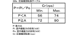
- a compressor rotation speed table 300a shown in FIG. 2 is stored in advance.
- This compressor rotation speed table 300a indicates the control range of the rotation speed Cr (unit: rps) of the compressor 21 when the air-conditioning apparatus 1 performs the defrosting operation, and indicates the sum Pi of the indoor functional forces of the indoor units 5a to 5c. Is determined according to the capacity ratio P divided by the sum of the rated capacities of the outdoor units 2 (hereinafter referred to as the sum of outdoor functional forces Po).
- the capacity ratio P when the capacity ratio P is less than a predetermined threshold capacity ratio A (for example, 75%), the minimum value of the compressor rotational speed Cr is 56 rps, the maximum value is 74 rps, In other words, the control range of the compressor rotational speed Cr is 56 rps to 74 rps.
- the capacity ratio P is greater than or equal to the threshold capacity ratio A, the minimum value of the compressor speed Cr is 72 rps and the maximum value is 90 rps. In other words, the control range of the compressor speed Cr is 72 rps. ⁇ 90 rps.
- the maximum value of the compressor rotation speed Cr in the compressor rotation speed table 300a is determined in advance by a test or the like, and is the rotation speed initially set when the air-conditioning apparatus 1 performs the defrosting operation. is there. As described above, it is preferable to end the defrosting operation early by increasing the rotation speed of the compressor 21 as much as possible at the time of the defrosting operation.
- the compressor 21 is started at the maximum value and is controlled so as to maintain this rotational speed during the defrosting operation.
- the minimum value of the compressor rotational speed Cr in the compressor rotational speed table 300a is also obtained and determined in advance by a test or the like, and the rotational speed control of the compressor 21 according to the suction pressure of the compressor 21 to be described later. It is the rotation speed which becomes the lower limit value when performing.
- the minimum value of the compressor rotational speed Cr is further reduced, and if the rotational speed Cr of the compressor 21 is further reduced, the pressure difference between the discharge pressure and the suction pressure of the compressor 21 is reduced, and the refrigerant circulation amount is significantly reduced.
- the rotation speed is such that the refrigerant is not circulated and the defrosting operation time becomes longer or the defrosting operation cannot be performed.
- the suction pressure of the compressor 21 is reduced due to pressure loss due to the height difference.
- the suction pressure of the compressor 21 may decrease during the defrosting operation.
- the degree of decrease is large, if the rotation speed Cr of the compressor 21 is continuously driven at the maximum value, There is a possibility that the suction pressure is greatly reduced and falls below the lower limit of performance. If the suction pressure falls below the lower limit of performance, the compressor may be damaged, and low pressure protection control is performed to stop the compressor so that the compressor is not damaged, resulting in a longer defrosting operation time. There is a problem that the return to heating operation is delayed.
- the suction pressure of the compressor 21 detected by the suction pressure sensor 32 is periodically taken, and the control of the rotational speed Cr of the compressor 21 according to the taken suction pressure is performed as shown in FIG. This is performed within the control range determined by the machine rotation speed table 300a.
- a first threshold pressure for example, 0.1 MPa
- the rotational speed Cr of the compressor 21 is set to a predetermined ratio. (Eg, 6 rps every 30 seconds).
- the rotational speed Cr of the compressor 21 is set to a predetermined value. Increase at a rate (eg, 6 rps every 30 seconds).
- a rate eg, 6 rps every 30 seconds.
- the rotational speed Cr of the compressor 21 is not changed.
- the control of the rotation speed Cr of the compressor 21 is stabilized by using two different threshold pressures when controlling the rotation speed Cr of the compressor 21 (if the rotation speed Cr is controlled with one threshold pressure, the rotation speed increases frequently. There is a possibility that the increase or decrease of the number Cr may be switched).
- the outdoor heat exchanger 23 functions as a condenser, so that the high-temperature refrigerant discharged from the compressor 21 flows into the outdoor heat exchanger 23 and melts the frost that has formed.
- the amount of frost formation in the heat exchanger 23 becomes the amount of frost formation according to the magnitude
- indoor expansion valves 52a to 52c having flow passage cross-sectional areas corresponding to the sizes of the indoor heat exchangers 51a to 51c are connected to the indoor heat exchangers 51a to 51c that function as evaporators during the defrosting operation.
- the refrigerant circulation amount of the refrigerant circuit 10 at the start of the defrosting operation depends on the size of the outdoor heat exchanger 23 and the sizes of the indoor heat exchangers 51a to 51c, and the outdoor heat exchanger 23 and the indoor heat The greater the difference in size from the exchangers 51a to 51c, the smaller the amount of refrigerant flowing out of the indoor heat exchangers 51a to 51c with respect to the amount of refrigerant flowing into the outdoor heat exchanger 23.
- coolant accumulates in the pipe
- the rotational speed Cr of the compressor 21 during the defrosting operation is controlled within the control range when the capacity ratio P is A or more: 72 rps to 90 rps. In this case, there is a possibility that the suction pressure is greatly reduced and falls below the lower limit of performance. If the suction pressure falls below the lower limit of performance, the compressor 21 may be damaged, or low pressure protection control for stopping the compressor 21 is executed so that the compressor 21 is not damaged, and the defrosting operation time becomes longer. There is a fear.
- the present invention like the compressor rotation speed table 300a, the sum Po of the outdoor functional force equivalent to the size of the outdoor heat exchanger 23 and the indoor function equivalent to the size of the indoor heat exchangers 51a to 51c.
- the capacity ratio P which is a ratio with the total force Pi
- the control range of the rotation speed Cr of the compressor 21 is set to 56 rps to 74 rps, and the suction pressure is reduced. The defrosting operation is performed while preventing the performance from falling below the lower limit.
- FIG. 3 shows a flow of processing performed by the CPU 210 of the outdoor unit control unit 200 when the air conditioning apparatus 1 performs the defrosting operation.
- ST represents a step
- the number following this represents a step number.
- FIG. 3 mainly describes the processing related to the present invention, and other processing, for example, air conditioning such as control of the refrigerant circuit corresponding to the operating conditions such as the set temperature and the air volume instructed by the user. Description of general processing related to the apparatus is omitted.
- the air conditioner 1 stores the rated capacities of the indoor units 5a to 5c input from the setting information input unit 250 in the storage unit 220 as initial settings at the time of installation.
- the CPU 210 calculates the sum Pi of the indoor functional forces using the stored rated capacities of the indoor units 5a to 5c, and calculates the sum Po of the rated capacities of the outdoor units 2 stored in the storage unit 220 in advance.
- the total sum Po is calculated by dividing the sum Pi of the indoor functional force by the rated capacity of the outdoor unit 2).
- the CPU 210 refers to the compressor rotation speed table 300 a stored in the storage unit 220, extracts the rotation speed Cr of the compressor 21 corresponding to the calculated capacity ratio P, and stores it in the storage unit 220.
- the CPU 210 determines whether or not the defrosting operation start condition is satisfied (ST1).
- the defrosting operation start condition is, for example, that the refrigerant temperature detected by the heat exchange temperature sensor 35 is lower by 5 ° C. or more than the outside air temperature detected by the outside air temperature sensor 36 after 30 minutes of the heating operation time has elapsed. This is a case where the state continues for 10 minutes or more, and the CPU 210 takes in the refrigerant temperature detected by the heat exchange temperature sensor 35 and the outside air temperature detected by the outside air temperature sensor 36 and determines whether or not the above condition is satisfied.
- the CPU 210 In ST1, if the defrosting operation start condition is not satisfied (ST1-No), the CPU 210 continues the heating operation (ST9) and returns the process to ST1. If the defrosting operation start condition is satisfied (ST1-Yes), the CPU 210 executes a defrosting operation preparation process (ST2). In the defrosting operation preparation process, the CPU 210 stops the compressor 21 and the outdoor fan 27 and switches the ports a and b to communicate with each other and the ports c and d to communicate with each other in the four-way valve 22. Thereby, in the refrigerant circuit 100, the outdoor heat exchanger 23 functions as a condenser and the indoor heat exchangers 51a to 51c function as evaporators, that is, when the cooling operation shown in FIG. 1 (A) is performed. It becomes a state. During the defrosting operation, the CPUs 510a to 510c of the indoor units 5a to 5c stop the indoor fans 55a to 55c.
- the CPU 210 starts up the compressor 21 at the rotational speed Cr stored in the storage unit 220 (ST3).
- the air-conditioning apparatus 1 starts the defrosting operation.
- the CPU 210 takes in the suction pressure of the compressor 21 detected by the low pressure sensor 32 (ST4). Then, the CPU 210 controls the rotational speed of the compressor 21 using the taken suction pressure (ST5). As described above, the CPU 210 controls the rotation speed of the compressor 21 within the control range determined by the compressor rotation speed table 300a shown in FIG. 2 in accordance with the taken-in suction pressure. If the pressure is equal to or lower than the above-described threshold pressure, the rotational speed Cr of the compressor 21 is decreased by a predetermined ratio, and if the suction pressure exceeds the threshold pressure, the rotational speed Cr of the compressor 21 is increased by a predetermined ratio. .
- CPU 210 determines whether or not a defrosting operation end condition is satisfied (ST6).
- the defrosting operation end condition is, for example, whether or not the temperature of the refrigerant flowing out of the outdoor heat exchanger 23 detected by the heat exchange temperature sensor 35 has become 10 ° C. or higher.
- the CPU 210 always takes in the refrigerant temperature detected by the heat exchange temperature sensor 35 and stores it in the storage unit 220.
- the CPU 210 refers to the stored refrigerant temperature, and determines whether or not the temperature is 10 ° C. or higher, that is, whether or not the defrosting operation end condition is satisfied.
- the defrosting operation end condition is determined in advance by a test or the like, and is a condition that the frost generated in the outdoor heat exchanger 23 is considered to have melted.
- the CPU 210 In ST9, if the defrosting operation termination condition is not satisfied (ST6-No), the CPU 210 returns the process to ST4 and continues the defrosting operation. If the defrosting operation end condition is satisfied (ST6-Yes), CPU 210 executes the heating operation resuming process (ST7). In the operation restart process, the CPU 210 stops the compressor 21 and switches the four-way valve 22 so that the ports a and d communicate with each other and the ports b and c communicate with each other. As a result, the refrigerant circuit 100 enters a state in which the outdoor heat exchanger 23 functions as an evaporator and the indoor heat exchangers 51a to 51c function as condensers.
- the CPU210 restarts heating operation (ST8) and returns a process to ST1.
- the CPU 210 controls the rotation speed of the compressor 21 and the outdoor fan 27 and the opening degree of the outdoor expansion valve 24 according to the heating capacity required from the indoor units 5a to 5c.
- the respective capacities of the indoor units 5a to 5c have been described with respect to the case where the operator manually inputs by operating the installation information input unit 250 when installing the air conditioner.
- the present invention is not limited to this.
- the capabilities of the indoor units 5a to 5c are included in the model information regarding the indoor units 5a to 5c stored in the storage units 520a to 520c of the indoor unit control units 500a to 500c, and the CPU 210 of the outdoor unit 2
- the model information includes basic information of the indoor units 5a to 5c, such as the model names and identification numbers of the indoor units 5a to 5c, in addition to the capabilities of the indoor units 5a to 5c. .
- the compressor rotation speed table 300b defines the control range of the rotation speed Cr of the compressor 21 when the air-conditioning apparatus 1 performs a defrosting operation according to the total sum Pi of indoor functional forces.
- the minimum value of the compressor rotational speed Cr is 56 rps, and the maximum value is In other words, the control range of the compressor rotational speed Cr is 56 rps to 74 rps.
- the minimum value of the compressor speed Cr is 72 rps and the maximum value is 90 rps, that is, the control of the compressor speed Cr.
- the range is 72 rps to 90 rps.
- the reason why the control range of the rotational speed Cr of the compressor 21 is determined according to only the sum Pi of the indoor functional forces in the compressor rotational speed table 300b will be described.
- the compressor 21 may be an inverter compressor or a constant speed compressor
- the outdoor heat exchanger 23 to be mounted are the same size, and the compressor 21 is operated.
- the outdoor unit 2 having the same size of the outdoor heat exchanger 23 and different rated capacities as in the latter case, even if the rated capacities are selected according to installation conditions, the outdoor In other words, the outdoor unit 2 that can be selected is determined.
- the rotational speed Cr of the compressor 21 is determined, as described in the first embodiment, the rotational speed Cr of the compressor 21 according to the capability ratio P between the total outdoor function sum Po and the total indoor function force Pi. If the control range of the compressor 21 is determined, the control range of the rotation speed Cr of the compressor 21 is set to 56 rps to 50 rps in spite of the low possibility of the low pressure protection control due to the reduction of the suction pressure, as described in the following specific example.
- the defrosting operation is performed at 74 rps, which may reduce the efficiency of the defrosting operation.
- the indoor units 5a to 5c are connected to the outdoor unit 2 that has the same size of the outdoor heat exchanger 23 and can have rated capacities of 10 kW, 12 kW, and 14 kW by controlling the operating capacity of the compressor 21.
- the threshold value of the sum Pi of the indoor functional forces at which the refrigerant circulation amount is reduced and the suction pressure is greatly reduced.
- the threshold capacity ratio is increased in the first embodiment. Since it is 75%, the sum of the capacity Pi of the indoor units 5a to 5c with respect to the threshold capacity ratio when the rated capacity of the outdoor unit 2 is 10 kW is 7.5 kW. Similarly, the sum of the capacity Pi of the indoor units 5a to 5c with respect to the threshold capacity ratio when the rated capacity of the outdoor unit 2 is 12 kW is 9.0 kW), and the threshold capacity when the rated capacity of the outdoor unit 2 is 14 kW. The total capacity Pi of the indoor units 5a to 5c with respect to the ratio is 10.5 kW.
- the control range of the rotational speed Cr of the compressor 21 is different depending on whether the threshold capacity ratio is 75% or more and the threshold capacity ratio is less than 75%.
- the low-pressure protection control is prevented by controlling the rotational speed Cr of the compressor 21 in the control range of 56 rps to 74 rps.
- the object of the present invention is to complete the defrosting operation as soon as possible by controlling the rotational speed Cr of the compressor 21 within a control range of 72 rps to 90 rps. Can be realized.
- the rated capacity of the outdoor unit 2 is 12 kW or 14 kW
- the sum of the capacity Pi of the indoor units 5a to 5c calculated with the threshold capacity ratio: 75% is 9.0 kW and 10.5 kW, respectively. It is larger than 7.5 kW which is the threshold capacity value B corresponding to the size of the outdoor heat exchanger 23 described above.
- the indoor units 5a to 5a are used when the rated capacity of the outdoor unit 2 is 12 kW.
- the rotational speed Cr of the compressor 21 is controlled within a control range of 56 rps to 74 rps.
- the rotational speed Cr of the compressor 21 is controlled within the control range of 56 rps to 74 rps when the sum of the capacities Pi of the indoor units 5a to 5c is less than 10.5 kW. Will be.
- 9.0 kW and 10.5 kW which are the sum of the capacities Pi of the indoor units 5a to 5c described above, are larger than the threshold capability value B corresponding to the size of the outdoor heat exchanger 23, which is 7.5 kW. Therefore, when the rated capacity of the outdoor unit 2 is 12 kW or 14 kW, the sum of the capacities Pi of the indoor units 5a to 5c that can normally control the rotational speed Cr of the compressor 21 within a control range of 72 rps to 90 rps (outdoor unit When the rated capacity of 2 is 12 kW, Pi is between 7.5 and 8.9 kW, and when the rated capacity of the outdoor unit 2 is 14 kW, Pi is between 7.5 and 10.4 kW)
- the number Cr is controlled in the control range of 56 rps to 74 rps, and the defrosting operation time may be prolonged by unnecessarily lowering the rotation speed Cr of the compressor 21 during the defrosting operation.
- the control range of the rotational speed Cr of the compressor 21 is set according to only the sum Pi of the indoor functional forces. Since the compressor rotational speed table 300b is determined and the control range of the rotational speed Cr of the compressor 21 is determined based on the compressor rotational speed table 300b, it is possible to prevent a decrease in low pressure during the defrosting operation. By reducing the rotational speed Cr of the compressor 21 during the defrosting operation unnecessarily, it is possible to prevent a decrease in the efficiency of the defrosting operation.
- the compressor rotation speed table 300c defines the control range of the rotation speed Cr of the compressor 21 when the air-conditioning apparatus 1 performs the defrosting operation according to the sum Pi of the indoor functional forces and the refrigerant pipe length Lr. It is.
- the refrigerant pipe length Lr indicates the length (unit: m) of the liquid pipe 8 and the gas pipe 9, and in the present embodiment, the maximum value of the refrigerant pipe length Lr will be described as 50 m.
- the refrigerant pipe length Lr is determined according to the size of the building where the air conditioner 1 is installed and the distance from the place where the outdoor unit 2 is installed to the room where the indoor units 5a to 5c are installed.
- the compressor rotation speed table 300c when the capacity ratio P is less than a predetermined threshold capacity ratio A (for example, 75%) and when it is greater than or equal to the threshold capacity ratio A (excluding this, the compressor 21 A control range of the rotational speed Cr is determined.
- a predetermined threshold capacity ratio A for example, 75%
- the compressor 21 A control range of the rotational speed Cr is determined.
- the minimum value Cr of the compressor 21 is 45 rps and the maximum value is In other words, the control range of the rotational speed Cr of the compressor 21 is 45 rps to 63 rps.
- the minimum value Cr of the compressor 21 is 56 rps and the maximum value is 74 rps, that is, the compressor 2
- the control range of the rotational speed Cr of 1 is 56 rps to 74 rps.
- the minimum value Cr of the compressor 21 is 62 rps and the maximum value is 80 rps. That is, the control range of the compressor rotational speed Cr is 62 rps to 80 rps. Further, when the refrigerant pipe length Lr is less than the threshold pipe length C, the minimum value Cr of the compressor 21 is 72 rps and the maximum value is 90 rps. The control range is 72 rps to 90 rps. .
- the reason why the control range of the rotation speed Cr of the compressor 21 is determined according to the capacity ratio P and the refrigerant pipe length Lr in the compressor rotation speed table 300c will be described.
- the air conditioner 1 when the air conditioner 1 is performing the defrosting operation, heat is exchanged between the frost and the refrigerant in the outdoor heat exchanger 23, and the outside air temperature is Since the condensing pressure does not increase and the discharge pressure of the compressor 21 does not increase due to being low, the pressure difference between the discharge pressure of the compressor 21 and the suction pressure becomes small, and the amount of refrigerant flowing through the gas pipe 9 decreases. And if the refrigerant
- the suction pressure of the compressor 21 may be reduced as compared with a short case.
- the compressor rotation speed table 300c that defines the control range of the starting rotation speed Cr of the compressor 21 according to the capacity ratio P and the refrigerant pipe length Lr is provided.
- a control range of the rotational speed Cr of the compressor 21 is determined based on the compressor rotational speed table 300c.
- the compressor rotational speed table 300c that defines the control range of the rotational speed Cr of the compressor 21 according to the capacity ratio P and the refrigerant pipe length Lr is provided.
- the air conditioner 1 including a plurality of outdoor units 2 having the same size of the outdoor heat exchanger 23 and different rated capacities, instead of the capacity ratio P, the sum of indoor functional forces Pi and You may make it have a compressor rotation speed table which defined the control range of the rotation speed Cr of the compressor 21 according to refrigerant
- the air conditioner of the present invention controls the rotation speed of the compressor during the defrosting operation within a control range corresponding to the capacity ratio, the total rated capacity of the indoor units, or the refrigerant pipe length.
- the defrosting operation is interrupted by the low pressure protection control, and the defrosting operation time becomes longer, thereby heating operation. There is no delay in returning to Japan.
- the rated capacity of the indoor units 5a to 5c is described when the operator operates and inputs the setting information input unit 250 at the time of initial setting when the air conditioner 1 is installed.
- the indoor units 5a to 5c store the model information including the information on their rated capacity in the storage units 520a to 520c, and when the air conditioner 1 is initially set, the indoor units 5a to 5c
- the model information of the machine 2 may be transmitted.
- the model information refers to the indoor units 5a to 5c necessary for management and control of the air conditioner 1, such as the model name and identification number of the indoor units 5a to 5c, in addition to the rated capacity of the indoor units 5a to 5c. It contains information.
- the refrigerant piping length Lr may be calculated by the CPU 210 of the outdoor unit 2 as described below, instead of being input by operating the setting information input unit 250 by the operator.
- the storage unit 220 of the outdoor unit control unit 200 stores the subcooling degree at the refrigerant outlet when the outdoor heat exchanger 23 functions as a condenser, the low pressure saturation temperature obtained using the suction pressure detected by the low pressure sensor 34, etc.
- the relational expression between the operating state quantity and the refrigerant pipe length Lr (for example, a table in which the refrigerant pipe length Lr is determined according to the degree of supercooling) is stored, and the CPU 210 performs the cooling operation of the air conditioner 1. Is obtained, and the refrigerant pipe length Lr is obtained using the above relational expression.
Landscapes
- Engineering & Computer Science (AREA)
- Mechanical Engineering (AREA)
- General Engineering & Computer Science (AREA)
- Physics & Mathematics (AREA)
- Thermal Sciences (AREA)
- Chemical & Material Sciences (AREA)
- Combustion & Propulsion (AREA)
- Air Conditioning Control Device (AREA)
- Compression-Type Refrigeration Machines With Reversible Cycles (AREA)
Priority Applications (5)
| Application Number | Priority Date | Filing Date | Title |
|---|---|---|---|
| US14/909,997 US10041714B2 (en) | 2013-08-08 | 2014-01-22 | Air conditioner |
| AU2014303955A AU2014303955B2 (en) | 2013-08-08 | 2014-01-22 | Air conditioning device |
| EP14834052.4A EP3032193B1 (de) | 2013-08-08 | 2014-01-22 | Klimaanlagenvorrichtung |
| CN201480023642.1A CN105229395B (zh) | 2013-08-08 | 2014-01-22 | 空气调节装置 |
| HK16101180.0A HK1213314A1 (zh) | 2013-08-08 | 2016-02-02 | 空氣調節裝置 |
Applications Claiming Priority (2)
| Application Number | Priority Date | Filing Date | Title |
|---|---|---|---|
| JP2013165037A JP5692302B2 (ja) | 2013-08-08 | 2013-08-08 | 空気調和装置 |
| JP2013-165037 | 2013-08-08 |
Publications (1)
| Publication Number | Publication Date |
|---|---|
| WO2015019628A1 true WO2015019628A1 (ja) | 2015-02-12 |
Family
ID=52460977
Family Applications (1)
| Application Number | Title | Priority Date | Filing Date |
|---|---|---|---|
| PCT/JP2014/051163 WO2015019628A1 (ja) | 2013-08-08 | 2014-01-22 | 空気調和装置 |
Country Status (7)
| Country | Link |
|---|---|
| US (1) | US10041714B2 (de) |
| EP (1) | EP3032193B1 (de) |
| JP (1) | JP5692302B2 (de) |
| CN (1) | CN105229395B (de) |
| AU (1) | AU2014303955B2 (de) |
| HK (1) | HK1213314A1 (de) |
| WO (1) | WO2015019628A1 (de) |
Cited By (2)
| Publication number | Priority date | Publication date | Assignee | Title |
|---|---|---|---|---|
| WO2016170680A1 (ja) * | 2015-04-24 | 2016-10-27 | 三菱電機株式会社 | 冷凍空調装置 |
| CN107560259A (zh) * | 2017-09-01 | 2018-01-09 | 广东美的暖通设备有限公司 | 多联机系统、多联机系统的低温启动控制方法和装置 |
Families Citing this family (18)
| Publication number | Priority date | Publication date | Assignee | Title |
|---|---|---|---|---|
| JP5590195B1 (ja) * | 2013-07-11 | 2014-09-17 | 株式会社富士通ゼネラル | 空気調和装置 |
| JP6201872B2 (ja) * | 2014-04-16 | 2017-09-27 | 三菱電機株式会社 | 空気調和機 |
| US10365025B2 (en) | 2014-11-25 | 2019-07-30 | Lennox Industries, Inc. | Methods and systems for operating HVAC systems in low load conditions |
| JP5999171B2 (ja) * | 2014-12-26 | 2016-09-28 | ダイキン工業株式会社 | 空気調和装置 |
| JP2016169904A (ja) * | 2015-03-12 | 2016-09-23 | パナソニックIpマネジメント株式会社 | 運転条件管理装置 |
| WO2017029695A1 (ja) * | 2015-08-14 | 2017-02-23 | 三菱電機株式会社 | 空気調和装置 |
| JP6535562B2 (ja) * | 2015-09-25 | 2019-06-26 | 東芝キヤリア株式会社 | ヒートポンプ装置及びヒートポンプシステム |
| WO2017077647A1 (ja) * | 2015-11-06 | 2017-05-11 | 三菱電機株式会社 | 室外機及びそれを用いた空気調和装置 |
| JP2017089950A (ja) * | 2015-11-06 | 2017-05-25 | 株式会社富士通ゼネラル | 空気調和システム |
| KR102500807B1 (ko) * | 2016-02-04 | 2023-02-17 | 엘지전자 주식회사 | 공기 조화기 및 그 제어방법 |
| CN110709649B (zh) * | 2017-06-12 | 2021-08-10 | 三菱电机株式会社 | 制冷循环装置 |
| CN108224703A (zh) * | 2017-12-25 | 2018-06-29 | 青岛海尔空调电子有限公司 | 空调的控制方法 |
| CN108386959B (zh) * | 2018-01-04 | 2019-12-03 | 青岛海尔空调器有限总公司 | 空调器及其除霜控制方法和控制装置 |
| JP6914451B2 (ja) * | 2018-09-28 | 2021-08-04 | 三菱電機株式会社 | 空気調和機 |
| WO2022059053A1 (ja) * | 2020-09-15 | 2022-03-24 | 東芝キヤリア株式会社 | 空気調和装置及び制御方法 |
| KR102556368B1 (ko) | 2020-10-30 | 2023-07-18 | 세메스 주식회사 | 반송 핸드 및 기판 처리 장치 |
| US11709004B2 (en) | 2020-12-16 | 2023-07-25 | Lennox Industries Inc. | Method and a system for preventing a freeze event using refrigerant temperature |
| CN115127195A (zh) * | 2022-07-19 | 2022-09-30 | 广东欧科空调制冷有限公司 | 一种多联式空调器除霜过程过热度控制方法 |
Citations (5)
| Publication number | Priority date | Publication date | Assignee | Title |
|---|---|---|---|---|
| JPS63259342A (ja) * | 1987-04-13 | 1988-10-26 | Matsushita Refrig Co | 多室形空気調和機 |
| JPS6463757A (en) * | 1987-03-16 | 1989-03-09 | Daikin Ind Ltd | Refrigerator |
| JPH01217146A (ja) * | 1988-02-23 | 1989-08-30 | Sanyo Electric Co Ltd | 除霜制御方法 |
| JPH11337234A (ja) * | 1998-05-29 | 1999-12-10 | Matsushita Refrig Co Ltd | 冷暖房装置 |
| JP2009228928A (ja) | 2008-03-19 | 2009-10-08 | Daikin Ind Ltd | 空気調和装置 |
Family Cites Families (11)
| Publication number | Priority date | Publication date | Assignee | Title |
|---|---|---|---|---|
| JP3091541B2 (ja) * | 1991-11-18 | 2000-09-25 | 三洋電機株式会社 | 空気調和機の制御装置 |
| US6047557A (en) * | 1995-06-07 | 2000-04-11 | Copeland Corporation | Adaptive control for a refrigeration system using pulse width modulated duty cycle scroll compressor |
| JP2001027455A (ja) * | 1999-05-13 | 2001-01-30 | Denso Corp | ヒートポンプ式空調装置 |
| CN1104605C (zh) * | 2000-06-02 | 2003-04-02 | 海尔集团公司 | 一拖多空调器改进的制冷系统 |
| JP3751208B2 (ja) * | 2001-02-23 | 2006-03-01 | 株式会社神戸製鋼所 | 多段可変速圧縮機の制御方法 |
| JP2006183979A (ja) * | 2004-12-28 | 2006-07-13 | Mitsubishi Heavy Ind Ltd | 冷媒配管長さ検知システムおよび冷媒配管長さ検知方法 |
| KR20090099613A (ko) * | 2008-03-18 | 2009-09-23 | 엘지전자 주식회사 | 공기 조화기 및 그 제어방법 |
| KR101547355B1 (ko) * | 2009-04-03 | 2015-08-25 | 엘지전자 주식회사 | 공기 조화기 및 공기 조화기의 제어 방법 |
| JP2012237482A (ja) * | 2011-05-11 | 2012-12-06 | Panasonic Corp | 空気調和機 |
| KR101256324B1 (ko) * | 2011-11-30 | 2013-04-18 | 엘지전자 주식회사 | 공기 조화기의 설치가이드 시스템의 이용방법 |
| CN102538272B (zh) * | 2012-02-09 | 2013-10-09 | 美的集团股份有限公司 | 空调系统及其除霜方法 |
-
2013
- 2013-08-08 JP JP2013165037A patent/JP5692302B2/ja active Active
-
2014
- 2014-01-22 WO PCT/JP2014/051163 patent/WO2015019628A1/ja active Application Filing
- 2014-01-22 CN CN201480023642.1A patent/CN105229395B/zh active Active
- 2014-01-22 AU AU2014303955A patent/AU2014303955B2/en active Active
- 2014-01-22 EP EP14834052.4A patent/EP3032193B1/de active Active
- 2014-01-22 US US14/909,997 patent/US10041714B2/en active Active
-
2016
- 2016-02-02 HK HK16101180.0A patent/HK1213314A1/zh unknown
Patent Citations (5)
| Publication number | Priority date | Publication date | Assignee | Title |
|---|---|---|---|---|
| JPS6463757A (en) * | 1987-03-16 | 1989-03-09 | Daikin Ind Ltd | Refrigerator |
| JPS63259342A (ja) * | 1987-04-13 | 1988-10-26 | Matsushita Refrig Co | 多室形空気調和機 |
| JPH01217146A (ja) * | 1988-02-23 | 1989-08-30 | Sanyo Electric Co Ltd | 除霜制御方法 |
| JPH11337234A (ja) * | 1998-05-29 | 1999-12-10 | Matsushita Refrig Co Ltd | 冷暖房装置 |
| JP2009228928A (ja) | 2008-03-19 | 2009-10-08 | Daikin Ind Ltd | 空気調和装置 |
Non-Patent Citations (1)
| Title |
|---|
| See also references of EP3032193A4 |
Cited By (4)
| Publication number | Priority date | Publication date | Assignee | Title |
|---|---|---|---|---|
| WO2016170680A1 (ja) * | 2015-04-24 | 2016-10-27 | 三菱電機株式会社 | 冷凍空調装置 |
| JPWO2016170680A1 (ja) * | 2015-04-24 | 2017-12-21 | 三菱電機株式会社 | 冷凍空調装置 |
| CN107560259A (zh) * | 2017-09-01 | 2018-01-09 | 广东美的暖通设备有限公司 | 多联机系统、多联机系统的低温启动控制方法和装置 |
| CN107560259B (zh) * | 2017-09-01 | 2020-03-03 | 广东美的暖通设备有限公司 | 多联机系统、多联机系统的低温启动控制方法和装置 |
Also Published As
| Publication number | Publication date |
|---|---|
| US20160178261A1 (en) | 2016-06-23 |
| EP3032193B1 (de) | 2022-04-20 |
| CN105229395A (zh) | 2016-01-06 |
| JP2015034657A (ja) | 2015-02-19 |
| HK1213314A1 (zh) | 2016-06-30 |
| EP3032193A4 (de) | 2017-06-14 |
| AU2014303955B2 (en) | 2016-08-11 |
| JP5692302B2 (ja) | 2015-04-01 |
| AU2014303955A1 (en) | 2015-11-12 |
| CN105229395B (zh) | 2017-08-25 |
| US10041714B2 (en) | 2018-08-07 |
| EP3032193A1 (de) | 2016-06-15 |
Similar Documents
| Publication | Publication Date | Title |
|---|---|---|
| JP5692302B2 (ja) | 空気調和装置 | |
| JP5574028B1 (ja) | 空気調和装置 | |
| JP5590195B1 (ja) | 空気調和装置 | |
| JP5549771B1 (ja) | 空気調和装置 | |
| JP5549773B1 (ja) | 空気調和装置 | |
| JP6225548B2 (ja) | 空気調和装置 | |
| JP6468300B2 (ja) | 空気調和装置 | |
| JP6870382B2 (ja) | 空気調和装置 | |
| JP2019020061A (ja) | 空気調和装置 | |
| JP2022069768A (ja) | 空気調和機 |
Legal Events
| Date | Code | Title | Description |
|---|---|---|---|
| WWE | Wipo information: entry into national phase |
Ref document number: 201480023642.1 Country of ref document: CN |
|
| 121 | Ep: the epo has been informed by wipo that ep was designated in this application |
Ref document number: 14834052 Country of ref document: EP Kind code of ref document: A1 |
|
| WWE | Wipo information: entry into national phase |
Ref document number: 2014834052 Country of ref document: EP |
|
| ENP | Entry into the national phase |
Ref document number: 2014303955 Country of ref document: AU Date of ref document: 20140122 Kind code of ref document: A |
|
| WWE | Wipo information: entry into national phase |
Ref document number: 14909997 Country of ref document: US |
|
| NENP | Non-entry into the national phase |
Ref country code: DE |