WO2015019402A1 - 永久磁石埋込型回転電機 - Google Patents
永久磁石埋込型回転電機 Download PDFInfo
- Publication number
- WO2015019402A1 WO2015019402A1 PCT/JP2013/071158 JP2013071158W WO2015019402A1 WO 2015019402 A1 WO2015019402 A1 WO 2015019402A1 JP 2013071158 W JP2013071158 W JP 2013071158W WO 2015019402 A1 WO2015019402 A1 WO 2015019402A1
- Authority
- WO
- WIPO (PCT)
- Prior art keywords
- permanent magnet
- magnet
- wall surface
- electric machine
- end plate
- Prior art date
Links
Images


Classifications
-
- H—ELECTRICITY
- H02—GENERATION; CONVERSION OR DISTRIBUTION OF ELECTRIC POWER
- H02K—DYNAMO-ELECTRIC MACHINES
- H02K1/00—Details of the magnetic circuit
- H02K1/06—Details of the magnetic circuit characterised by the shape, form or construction
- H02K1/22—Rotating parts of the magnetic circuit
- H02K1/32—Rotating parts of the magnetic circuit with channels or ducts for flow of cooling medium
-
- H—ELECTRICITY
- H02—GENERATION; CONVERSION OR DISTRIBUTION OF ELECTRIC POWER
- H02K—DYNAMO-ELECTRIC MACHINES
- H02K1/00—Details of the magnetic circuit
- H02K1/06—Details of the magnetic circuit characterised by the shape, form or construction
- H02K1/12—Stationary parts of the magnetic circuit
- H02K1/16—Stator cores with slots for windings
-
- H—ELECTRICITY
- H02—GENERATION; CONVERSION OR DISTRIBUTION OF ELECTRIC POWER
- H02K—DYNAMO-ELECTRIC MACHINES
- H02K1/00—Details of the magnetic circuit
- H02K1/06—Details of the magnetic circuit characterised by the shape, form or construction
- H02K1/22—Rotating parts of the magnetic circuit
- H02K1/27—Rotor cores with permanent magnets
- H02K1/2706—Inner rotors
- H02K1/272—Inner rotors the magnetisation axis of the magnets being perpendicular to the rotor axis
- H02K1/274—Inner rotors the magnetisation axis of the magnets being perpendicular to the rotor axis the rotor consisting of two or more circumferentially positioned magnets
- H02K1/2753—Inner rotors the magnetisation axis of the magnets being perpendicular to the rotor axis the rotor consisting of two or more circumferentially positioned magnets the rotor consisting of magnets or groups of magnets arranged with alternating polarity
- H02K1/276—Magnets embedded in the magnetic core, e.g. interior permanent magnets [IPM]
- H02K1/2766—Magnets embedded in the magnetic core, e.g. interior permanent magnets [IPM] having a flux concentration effect
-
- H—ELECTRICITY
- H02—GENERATION; CONVERSION OR DISTRIBUTION OF ELECTRIC POWER
- H02K—DYNAMO-ELECTRIC MACHINES
- H02K1/00—Details of the magnetic circuit
- H02K1/06—Details of the magnetic circuit characterised by the shape, form or construction
- H02K1/22—Rotating parts of the magnetic circuit
- H02K1/28—Means for mounting or fastening rotating magnetic parts on to, or to, the rotor structures
- H02K1/30—Means for mounting or fastening rotating magnetic parts on to, or to, the rotor structures using intermediate parts, e.g. spiders
-
- H—ELECTRICITY
- H02—GENERATION; CONVERSION OR DISTRIBUTION OF ELECTRIC POWER
- H02K—DYNAMO-ELECTRIC MACHINES
- H02K9/00—Arrangements for cooling or ventilating
- H02K9/19—Arrangements for cooling or ventilating for machines with closed casing and closed-circuit cooling using a liquid cooling medium, e.g. oil
-
- H—ELECTRICITY
- H02—GENERATION; CONVERSION OR DISTRIBUTION OF ELECTRIC POWER
- H02K—DYNAMO-ELECTRIC MACHINES
- H02K11/00—Structural association of dynamo-electric machines with electric components or with devices for shielding, monitoring or protection
- H02K11/20—Structural association of dynamo-electric machines with electric components or with devices for shielding, monitoring or protection for measuring, monitoring, testing, protecting or switching
- H02K11/25—Devices for sensing temperature, or actuated thereby
Definitions
- the present invention relates to a permanent magnet embedded type rotating electrical machine in which a permanent magnet is embedded on the outer peripheral side of a rotor core, and more particularly to a cooling structure for a permanent magnet embedded in a rotor core.
- a permanent magnet is disposed in a cavity formed in the rotor core so as to extend in the direction of the rotation axis, and an insulating member is formed so as to cover the entire inner wall surface of the cavity.
- the permanent magnet was cooled by flowing a coolant through a cooling flow path constituted by the surface of the insulating member and the inner surface of the insulating member (see, for example, Patent Document 1).
- annular outer yoke portion in which a permanent magnet is embedded, an annular inner yoke portion disposed inside the outer yoke portion, and an outer yoke portion
- the rotor is configured by the ribs connecting the inner peripheral surface of the inner yoke portion and the outer peripheral surface of the inner yoke portion, and the groove portion is formed on the inner peripheral surface of the outer yoke portion so as to extend from one end portion in the axial direction to the other end portion.
- the cooling oil supplied to the through hole constituted by the inner peripheral surface of the outer yoke portion, the outer peripheral surface of the inner yoke portion and the ribs is guided into the groove portion by centrifugal force, and flows smoothly through the groove portion.
- the permanent magnet was cooled (for example, refer to Patent Document 2).
- the present invention has been made to solve the above-described problems.
- the amount of the adhesive for fixing the permanent magnet to the inner wall surface of the magnet housing hole is reduced to reduce the cross-sectional area of the magnet housing hole.
- the distance between the magnet housing hole and the inner wall surface is shortened to suppress the decrease in the amount of magnetic flux of the permanent magnet, and the cooling flow path is configured so that the refrigerant directly cools the permanent magnet. It is an object of the present invention to obtain a permanent magnet embedded type rotating electrical machine that can be cooled rapidly.
- a permanent magnet embedded rotary electric machine is formed by stacking and integrating an annular stator core, a stator having a stator coil wound around the stator core, and an electromagnetic steel plate, and a shaft.
- a rotor core that is fixed to the stator core and rotatably disposed inside the stator core, and a plurality of magnets that are formed so as to penetrate the outer peripheral side of the rotor core in the axial direction and are arranged in the circumferential direction.
- the adhesive is disposed only between the outer wall surface located radially outward of the inner wall surface of the magnet housing hole and the outer surface located radially outward of the surface of the permanent magnet,
- a permanent magnet is offset to the outer wall surface of the magnet housing hole, and a cooling flow path through which the refrigerant flows is an inner surface located radially inward of the surface of the permanent magnet and a diameter of the inner wall surface of the magnet housing hole. It is comprised by the inner wall surface located in a direction inner side.
- the permanent magnet is fixed to the outer wall surface positioned radially outward of the inner wall surface of the magnet housing hole, and the cooling flow path through which the refrigerant flows is positioned radially inward of the surface of the permanent magnet. And an inner wall surface located radially inward of the inner wall surface of the magnet housing hole. Therefore, the refrigerant flowing through the cooling flow path is in direct contact with the inner surface of the permanent magnet, and the permanent magnet can be effectively cooled.
- the adhesive is disposed only between the outer wall surface located radially outward of the inner wall surface of the magnet housing hole and the outer surface located radially outward of the surface of the permanent magnet.
- the amount of the agent is small, and the cross-sectional area of the magnet housing hole can be reduced. Therefore, the distance between the permanent magnet and the inner wall surface of the magnet housing hole is shortened, and an increase in magnetic resistance between the permanent magnet and the rotor core is suppressed. Thereby, the fall of the magnetic flux amount of the permanent magnet resulting from the increase in magnetic resistance can be suppressed.
- FIG. 1 is a cross-sectional view showing a permanent magnet embedded type rotating electrical machine according to Embodiment 1 of the present invention
- FIG. 2 is an end face showing a rotor core in the permanent magnet embedded type rotating electrical machine according to Embodiment 1 of the present invention
- 3 is a perspective view for explaining a state in which a rotor core is incorporated in a stator in a permanent magnet embedded rotary electric machine according to Embodiment 1 of the present invention.
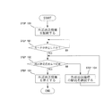
- FIG. 4 is according to Embodiment 1 of the present invention. It is a flow which shows the drive control method of the external oil feeding apparatus in a permanent magnet embedded type rotary electric machine. In FIG. 1, arrows indicate the flow of cooling oil.
- an embedded permanent magnet rotating electrical machine 100 includes an annular stator 1, a cylindrical frame 7 that houses and holds the stator 1 inside, and bearings 12 and 13, respectively.
- the front frame 10 and the rear frame 11 that are disposed at both ends in the axial direction of the frame 7 and form a sealed space together with the frame 7, and the shaft 16 are supported by the bearings 12 and 13, and rotate inside the stator 1.
- the rotor 15, the external oil feeding mechanism 35, and the control device 40 that controls the driving of the external oil feeding mechanism 35 are provided.
- the stator 1 has an annular stator core 2 and a stator coil 4 attached to the stator core 2.
- the iron core block 3 includes an arc-shaped core back portion 3a and teeth 3b protruding radially inward from the circumferential center position of the inner peripheral surface of the core back portion 3a.
- the stator core 2 is configured in an annular shape by aligning the circumferential side surfaces of the core back portion 3a with each other and arranging 12 core blocks 3 in the circumferential direction.
- a concentrated winding coil 4a produced by winding a conductor wire a plurality of times is attached to the teeth 3b of each iron core block 3.
- the stator coil 4 is configured by the 12 concentrated winding coils 4a.
- the frame 7 is manufactured by fitting and integrating an aluminum cylindrical inner frame 9 inside an iron cylindrical outer frame 8. Then, the twelve core blocks 3 to which the concentrated winding coils 4a are attached are arranged in an annular shape by butting the side surfaces in the circumferential direction of the core back portion 3a, and are press-fitted and fixed in the frame 7, thereby fixing the stator 1 Is assembled.
- the rotor 15 includes an annular rotor core 17, a shaft 16 that is press-fitted and fixed in a shaft insertion hole 19 formed so as to penetrate the axial center position of the rotor core 17, and the rotor core 17.
- Sixteen permanent magnets 21 mounted so as to penetrate the outer peripheral side, and a first end plate 25 that is press-fitted and fixed to the shaft 16 so as to be in contact with both axial end surfaces of the rotor core 17.
- a second end plate 29 is provided.
- the rotor core 17 has a shaft insertion hole 19 that is formed by laminating and integrating an annular core piece punched from a thin magnetic steel sheet with the through hole 18 positioned, and penetrating the axial center position.
- Each of the magnet housing holes 20 has a substantially rectangular shape in which a cross section orthogonal to the axial direction of the shaft 16 is constant in the axial direction, penetrates the outer peripheral side of the rotor core 17 in the axial direction, and has an equal pitch of 8 in the circumferential direction. Paired.
- the pair of magnet housing holes 20 is arranged in a V shape that opens radially outward.
- a portion located radially outward of the inner wall surface of the magnet housing hole 20 is referred to as an outer wall surface 20a, and a portion located radially inward is referred to as an inner wall surface 20b.
- the inner wall surface constituted by the radially outer long side of the cross section of the magnet housing hole 20 is the outer wall surface 20a, and the inner wall surface constituted by the radially inner long side of the section is the inner wall surface 20b.
- the length direction of the long side of the cross section of the magnet housing hole 20 is defined as the width direction.
- the permanent magnet 21 has a rectangular cross section orthogonal to the axial direction of the shaft 16 and is housed in each of the magnet housing holes 20.
- a portion located radially outward of the surface of the permanent magnet 21 is referred to as an outer surface 21a, and a portion located radially inward is referred to as an inner surface 21b. That is, the surface constituted by the long outer side in the radial direction of the cross section of the permanent magnet 21 is the outer surface 21a, and the surface constituted by the long inner side in the radial direction of the cross section is the inner surface 21b.
- the length direction of the long side of the cross section of the permanent magnet 21 is the width direction.
- the permanent magnet 21 housed in the magnet housing hole 20 is bonded and fixed only to the outer wall surface 20a of the magnet housing hole 20 with an adhesive 22 only on the outer surface 21a. As a result, the permanent magnet 21 is shifted toward the outer wall surface 20 a in the magnet housing hole 20, and a gap is formed between the inner surface 21 b of the permanent magnet 21 and the inner wall surface 20 b of the magnet housing hole 20. This gap penetrates the rotor core 17 in the axial direction and constitutes a cooling channel 23.
- the pair of permanent magnets 21 housed in the pair of magnet housing holes 20 are magnetized so as to have the same magnetic pole.
- the eight pairs of permanent magnets 21 are arranged so that the magnetic poles are alternately different in the circumferential direction.
- the permanent magnet 21 is configured by arranging six magnet blocks 210 formed in a strip shape having a rectangular cross section orthogonal to the axial direction of the shaft 16 in a line in the axial direction.
- the rotor grooves 24 having the groove direction as the axial direction are each formed in a groove shape having the same rectangular cross section, and are formed on the outer peripheral surface of the rotor core 17 so as to extend from one end to the other end in the axial direction of the rotor core 17. Then, eight are arranged at an equiangular pitch in the circumferential direction. The center in the circumferential direction of these rotor grooves 24 is located between adjacent magnetic poles.
- the first end plate 25 is made of a ring-shaped flat plate having an outer diameter substantially equal to the outer diameter of the rotor core 17 and having a shaft insertion hole 26 at the axial center position.
- the introduction flow path 27 is formed by recessing one surface of the first end plate 25 by a certain depth, leaving the outer peripheral edge thereof.
- the first discharge passages 28 pass through the first end plate 25 in the axial direction so as to communicate with the outer peripheral portion of the introduction flow passage 27 and the other surface side of the first end plate 25, respectively, and are equidistant in the circumferential direction. 8 are formed.
- the first end plate 25 is press-fitted and fixed to the shaft 16 from one side in the axial direction with one surface thereof facing the rotor core 17 through the shaft 16 through the shaft insertion hole 26. One surface of the first end plate 25 is in contact with one end surface of the rotor core 17 in the axial direction, and the opening of the introduction flow path 27 is closed.
- a cooling channel 23 formed in the rotor core 17 is connected to the introduction channel 27.
- the first discharge passages 28 are located on the radially outer sides of the cooling passages 23.
- the second end plate 29 is made of a ring-shaped flat plate having an outer diameter substantially equal to the outer diameter of the rotor core 17 and having a shaft insertion hole 30 at the axial center position.
- the introduction channel 31 is formed by denting one surface of the second end plate 29 by a certain depth, leaving the outer peripheral edge portion.
- the second discharge passages 32 pass through the second end plate 29 in the axial direction so as to communicate with the outer peripheral portion of the introduction flow channel 31 and the other surface side of the second end plate 29, respectively, and have an equal pitch in the circumferential direction. 8 are formed.
- the second end plate 29 is formed in the same shape as the first end plate 25.
- the second end plate 29 is press-fitted and fixed to the shaft 16 from the other side in the axial direction with the one surface facing the rotor core 17 through the shaft 16 through the shaft insertion hole 30.
- One surface of the second end plate 29 is in contact with the other axial end surface of the rotor core 17, and the opening of the introduction channel 31 is closed.
- a cooling channel 23 formed in the rotor core 17 is connected to the introduction channel 31.
- the second discharge passages 32 are located on the radially outer sides of the cooling passages 23.
- the shaft 16 is formed in the in-axis flow path 33 and the first end plate 25 by branching in the axial direction from the in-axis flow path 33 in the radial direction. And a branch channel 34 that communicates with the introduction channel 27.
- a supply pipe 36 connects the discharge port of the external oil feed mechanism 35 which is a refrigerant supply means and the inlet of the in-axis flow path 33 of the shaft 16.
- a return pipe 37 connects the oil pan 38 attached below the frame 7, the outlet of the in-axis passage 33 of the shaft 16, and the suction port of the external oil feed mechanism 35.
- the control device 40 controls the driving of the external oil feeding mechanism 35 based on the detected temperature from a temperature detector 41 such as a thermistor disposed in the stator core 2.
- the permanent magnet embedded type rotating electrical machine 100 configured as described above is supplied with power to the stator coil 4 from an external power source, for example, and operates as an 8-pole 12-slot inner rotor type synchronous motor.
- the cooling oil is pumped from the supply pipe 36 to the in-shaft flow path 33 as indicated by an arrow in FIG. 27 flows in.
- the cooling oil flowing into the introduction flow path 27 flows radially outward through the introduction flow path 27 and flows into the cooling flow path 23.
- the cooling oil that has flowed into the cooling flow path 23 flows to the other side in the axial direction through the cooling flow path 23, absorbs the heat of the permanent magnet 21, and is discharged from the second discharge path 32.
- the cooling oil discharged from the second discharge path 32 is scattered by centrifugal force, hits the rear coil end of the stator coil 4, absorbs the heat of the stator coil 4, and is collected in the oil pan 38.
- a portion of the cooling oil that has flowed radially outward through the introduction flow path 27 is discharged from the first discharge path 28.
- the cooling oil discharged from the first discharge path 28 is scattered by centrifugal force, hits the front side coil end of the stator coil 4, absorbs the heat of the stator coil 4, and is collected in the oil pan 38.
- the cooling oil collected in the oil pan 38 is returned to the external oil feeding mechanism 35 through the return pipe 37 together with the cooling oil discharged from the outlet of the in-axis passage 33 of the shaft 16.
- the permanent magnet 21 has the outer surface 21 a bonded and fixed to the outer wall surface 20 a of the magnet housing hole 20 and is biased toward the outer wall surface 20 a in the magnet housing hole 20.
- a cooling flow path 23 is formed between the inner surface 21 b of the permanent magnet 21 and the inner wall surface 20 b of the magnet housing hole 20. Therefore, since the cooling oil flowing through the cooling flow path 23 is in direct contact with the inner surface 21b of the permanent magnet 21, the permanent magnet 21 can be effectively cooled.
- the adhesive 22 for fixing the permanent magnet 21 is applied only between the outer surface 21 a of the permanent magnet 21 and the outer wall surface 20 a of the magnet housing hole 20. Therefore, the amount of adhesive 22 used is reduced, and the cost can be reduced. Further, since the cross-sectional area of the magnet housing hole 20 can be reduced by the amount of the adhesive 22 reduced, the distance between the permanent magnet 21 and the inner wall surface of the magnet housing hole 20 is shortened, and the permanent magnet 21 and the rotor core. The increase in magnetoresistance between the two is suppressed. Thereby, the fall of the magnetic flux amount of the permanent magnet 21 resulting from the increase in magnetic resistance can be suppressed.
- a rotor groove 24 is formed on the outer peripheral surface of the rotor core 17 so as to extend from one end to the other end in the axial direction. Therefore, the cooling oil leaking to the outer peripheral side from between the core pieces constituting the rotor core 17 flows through the rotor groove 24 in the axial direction. Thereby, the torque fall by cooling oil staying in the air gap between the stator core 2 and the rotor core 17 is suppressed.
- the first end plate 25 and the second end plate 29 are made in the same shape. Therefore, the first end plate 25 can also be used as the second end plate 29, and the number of parts can be reduced.
- the first end plate 25 includes a first discharge path 28 that communicates the outer peripheral portion of the introduction flow path 27 and the other surface side of the first end plate 25. Therefore, a part of the cooling oil flowing through the introduction flow path 27 is discharged from the first discharge path 28 and exposed to the front side coil end of the stator coil 4 by centrifugal force, so that the temperature rise of the stator coil 4 is suppressed. be able to.
- the second end plate 29 includes a second discharge path 32 that communicates the outer peripheral portion of the introduction flow path 31 and the other surface side of the second end plate 29. Therefore, the cooling oil that has flowed through the cooling flow path 23 is discharged from the second discharge path 32 and is applied to the rear coil end of the stator coil 4 by centrifugal force, so that an increase in temperature of the stator coil 4 can be suppressed. .
- the control device 40 is set, for example, by adding a safety factor to the data in the correspondence table between the temperature detected by the temperature detector 41 and the temperature of the permanent magnet 21 and the temperature at which the permanent magnet 21 is thermally demagnetized. Stored judgment values are stored.
- the control device 40 drives the external oil feeding mechanism 35 (step 100). Thereby, the cooling oil is supplied to the cooling flow path 23 via the in-axis flow path 33, the branch flow path 34, and the introduction flow path 27, and the permanent magnet 21 is cooled.
- the control device 40 determines whether or not the motor has stopped (step 101). When determining that the motor has stopped, the control device 40 estimates the temperature of the permanent magnet 21 based on the temperature detected by the temperature detector 41 and the stored data. And it is determined whether magnet estimated temperature is below a determination value (step 102). If it is determined in step 102 that the estimated magnet temperature is equal to or lower than the determination value, it is determined that the permanent magnet 21 is sufficiently cooled, and the driving of the external oil feeding mechanism 35 is stopped (step 103). Thereby, the permanent magnet 21 is cooled by the cooling oil staying in the cooling flow path 23.
- step 102 If it is determined in step 102 that the estimated magnet temperature exceeds the determination value, it is determined that the permanent magnet 21 is not sufficiently cooled, and the driving of the external oil feeding mechanism 35 is continued (step 104). Return. Thereby, the cooled cooling oil is supplied to the cooling flow path 23 and used for cooling the permanent magnet 21.
- the temperature of the permanent magnet 21 is estimated based on the temperature detected by the temperature detector 41 disposed in the stator core 2, and the estimated magnet temperature Is less than or equal to a determination value, and when the estimated magnet temperature is less than or equal to the determination value, the driving of the external oil feeding mechanism 35 is stopped. Thereby, the power consumption of the external oil feed mechanism 35 can be reduced.
- the external oil feed mechanism 35 is continuously driven and the cooled cooling oil is supplied to the cooling flow path 23, so that an excessive temperature rise of the permanent magnet 21 occurs. And thermal demagnetization of the permanent magnet 21 can be prevented.
- the introduction flow paths 27 and 31 are formed by recessing one surface of the first end plate 25 and the second end plate 29 by a certain depth, leaving the outer peripheral edge portions.
- each of the introduction channels has a channel groove formed on one surface of the first end plate and the second end plate so as to reach the vicinity of the outer peripheral end from the shaft insertion hole, with the groove direction as the radial direction.
- eight may be arranged at an equal pitch.
- the first discharge plate and the second discharge passage communicate with the outer peripheral portions of the flow channel grooves and the other end sides of the first end plate and the second end plate. What is necessary is just to form through an end plate.
- the temperature detector 41 is disposed in the core back portion 3a of the stator core 2.
- the location of the temperature detector 41 is not limited to the core back portion 3a. Any place where the temperature of the permanent magnet 21 can be indirectly measured is acceptable.
- the coil end of the stator coil 4 may be used.
- FIG. FIG. 5 is a sectional view showing a permanent magnet embedded type rotating electric machine according to Embodiment 2 of the present invention.
- the in-axis flow path 33 ⁇ / b> A is formed so as to extend from one end in the axial direction at the axial center position of the shaft 16 ⁇ / b> A to a position radially below the introduction flow path 27 formed in the first end plate 25.
- a branch channel 34 is formed in the shaft 16A so as to communicate the other axial end of the in-axis channel 33A with the introduction channel 27.
- Other configurations are the same as those in the first embodiment.
- the shaft flow path 33A is formed only on the front side of the shaft 16A, so that the cost of the shaft 16A can be reduced.
- FIG. FIG. 6 is a cross-sectional view showing a permanent magnet embedded rotary electric machine according to Embodiment 3 of the present invention.
- the flow path cross-sectional areas of the first discharge path 28, the cooling flow path 23, and the second discharge path 32 increase in the order of the first discharge path 28, the cooling flow path 23, and the second discharge path 32.
- Other configurations are the same as those in the first embodiment.
- the flow passage cross-sectional area of the first discharge passage 28 is smaller than the flow passage cross-sectional area of the cooling flow passage 23, and thus the circulation passage through the introduction flow passage 27.
- the amount of cooling oil flowing out from the first discharge path 28 is limited. Thereby, the quantity of the cooling oil supplied to the cooling flow path 23 is sufficiently secured, and the cooling performance of the permanent magnet 21 is not lowered.
- the flow path cross-sectional area of the second discharge path 32 is larger than the flow path cross-sectional area of the cooling flow path 23, the cooling oil that has flowed through the cooling flow path 23 easily flows out of the second discharge path 32. Thereby, the flow speed of the cooling oil flowing through the cooling flow path 23 is increased, and the performance of cooling the permanent magnet 21 is enhanced.
- FIG. 7 is an end view showing a rotor core in a permanent magnet embedded rotary electric machine according to Embodiment 4 of the present invention.
- the magnet housing hole 20A is formed in the rotor core 17A so that both sides in the width direction of the inner wall surface 20b protrude outward in the radial direction.
- the protrusions on both sides in the width direction of the inner wall surface 20b of the magnet housing hole 20A constitute the support portion 43.
- Other configurations are the same as those in the first embodiment.
- both sides in the width direction of the inner surface 21b of the permanent magnet 21 housed in the magnet housing hole 20A are supported by the support portions 43. Therefore, since the layer of the adhesive 22 that bonds the outer surface 21a of the permanent magnet 21 and the outer wall surface 20a of the magnet housing hole 20A can be thinned, the thinner the layer of the adhesive 22, the more the magnet housing hole 20A has. A cross-sectional area can be made small and the fall of the magnetic flux amount of the permanent magnet 21 is suppressed.
- FIG. 8 is an end view showing a rotor core in an embedded permanent magnet rotating electrical machine according to Embodiment 5 of the present invention
- FIG. 9 is a rotor in an embedded permanent magnet rotating electrical machine according to Embodiment 5 of the present invention. It is an end view which shows the state at the time of the motor stop of an iron core.
- the magnet housing hole 20B is formed in the rotor core 17B in a V shape in which the width of the inner wall surface 20b becomes gradually narrower inward in the radial direction.
- the cooling channel 23B is formed in a triangular channel cross section.
- Other configurations are the same as those in the first embodiment.
- the cooling flow path 23B is formed in a triangular flow path cross section. Therefore, even if the pressure of the cooling oil is lower than the pressure of the cooling oil supplied to the cooling channel 23 formed in the rectangular channel cross section, the cooling performance equivalent to that of the cooling channel 23 can be obtained. The power consumption of the feeding mechanism 35 can be reduced.
- the contact area between the cooling oil 44 staying in the cooling flow path 23B and the permanent magnet 21 is increased. Therefore, the permanent magnet 21 can be effectively cooled by the cooling oil 44 staying in the cooling flow path 23B when the motor is stopped.
- the two permanent magnets constituting the magnetic pole are arranged in a V shape that is opened radially outward from the shaft.
- the arrangement of the permanent magnets is limited to this.
- the permanent magnets may be arranged at equiangular pitches in the circumferential direction so as to contact the same cylindrical surface, and each of the permanent magnets may constitute a magnetic pole.
- the permanent magnet is divided into six magnet blocks in the axial direction.
- the permanent magnet may be configured as an integrated body in which six magnet blocks are connected.
- the permanent magnet has a rectangular cross section perpendicular to the axial direction of the shaft.
- the cross section of the permanent magnet is not limited to a rectangular shape, for example, an arc shape curved in an arc shape. Good.
- the magnet housing hole is formed in a cross-sectional shape that matches the cross-sectional shape of the permanent magnet.
Abstract
Description
図1はこの発明の実施の形態1に係る永久磁石埋込型回転電機を示す断面図、図2はこの発明の実施の形態1に係る永久磁石埋込型回転電機における回転子鉄心を示す端面図、図3はこの発明の実施の形態1に係る永久磁石埋込型回転電機における固定子に回転子鉄心を組み込んだ状態を説明する斜視図、図4はこの発明の実施の形態1に係る永久磁石埋込型回転電機における外部油送機器の駆動制御方法を示すフローである。なお、図1中、矢印は冷却油の流れを示している。
制御装置40は、固定子鉄心2に配設されたサーミスタなどの温度検出器41からの検出温度に基づいて外部油送機構35の駆動を制御する。
オイルパン38に集められた冷却油は、シャフト16の軸内流路33の出口から排出された冷却油とともに、戻り配管37を通って外部油送機構35に戻される。
図5はこの発明の実施の形態2に係る永久磁石埋込型回転電機を示す断面図である。
なお、他の構成は上記実施の形態1と同様に構成されている。
図6はこの発明の実施の形態3に係る永久磁石埋込型回転電機を示す断面図である。
なお、他の構成は上記実施の形態1と同様に構成されている。
第2排出路32の流路断面積が冷却流路23の流路断面積より大きくなっているので、冷却流路23を流通してきた冷却油が第2排出路32から流出しやすくなる。これにより、冷却流路23内を流通する冷却油の流速が速くなり、永久磁石21を冷却する性能が高められる。
図7はこの発明の実施の形態4に係る永久磁石埋込型回転電機における回転子鉄心を示す端面図である。
なお、他の構成は上記実施の形態1と同様に構成されている。
図8はこの発明の実施の形態5に係る永久磁石埋込型回転電機における回転子鉄心を示す端面図、図9はこの発明の実施の形態5に係る永久磁石埋込型回転電機における回転子鉄心のモータ停止時の状態を示す端面図である。
なお、他の構成は上記実施の形態1と同様に構成されている。
また、上記各実施の形態では、8極12スロットの回転電機について説明しているが、極数およびスロット数は、8極12スロットに限定されないことは言うまでもないことである。
また、上記各実施の形態では、永久磁石がシャフトの軸方向と直交する断面を矩形に作製されているが、永久磁石の断面は矩形に限定されず、例えば円弧状に湾曲した円弧形でもよい。この場合、磁石収納穴は、永久磁石の断面形状に適合する断面形状に形成される。
Claims (8)
- 円環状の固定子鉄心、および上記固定子鉄心に巻装された固定子コイルを有する固定子と、
電磁鋼板を積層一体化して構成され、シャフトに固着されて上記固定子鉄心の内側に回転可能に配置される回転子鉄心、それぞれ、上記回転子鉄心の外周側を軸方向に貫通するように形成されて周方向に複数配設された磁石収納穴、および上記磁石収納穴のそれぞれに収納された永久磁石を有する回転子と、を備えた永久磁石埋込型回転電機において、
接着剤が、上記磁石収納穴の内壁面の径方向外方に位置する外側壁面と上記永久磁石の表面の径方向外方に位置する外側表面との間にのみ配設されて、上記永久磁石が上記磁石収納穴の上記外側壁面に片寄せ固定され、
冷媒が流れる冷却流路が、上記永久磁石の表面の径方向内方に位置する内側表面と上記磁石収納穴の内壁面の径方向内方に位置する内側壁面とにより構成されることを特徴とする永久磁石埋込型回転電機。 - 上記シャフトに固着されて一面が上記回転子鉄心の軸方向一端面に接するように配設された第1端板を備え、
軸内流路が、上記シャフトの軸心位置に軸方向に延びるように形成され、
分岐流路が、上記軸内流路から径方向に分岐して上記シャフトの外周面に至るように上記シャフトに形成され、
導入流路が、上記第1端板の上記一面に、上記分岐流路と上記冷却流路とを連通するように形成され、
第1排出路が、上記導入流路の外周部と上記第1端板の他面側とを連通するように上記第1端板に形成されていることを特徴とする請求項1記載の永久磁石埋込型回転電機。 - 上記軸内流路が、上記シャフトの軸方向一端から上記第1端板の固着位置までの軸方向領域にのみ形成されていることを特徴とする請求項2記載の永久磁石埋込型回転電機。
- 上記シャフトに固着されて一面が上記回転子鉄心の軸方向他端面に接するように配設された第2端板を備え、
第2排出路が、上記冷却流路と上記第2端板の他面側とを連通するように上記第2端板に形成され、
上記第1排出路の流路断面積が、上記冷却流路の流路断面積より小さく、かつ上記第2排出路の流路断面積が、上記冷却流路の流路断面積より大きいことを特徴とする請求項2又は請求項3記載の永久磁石埋込型回転電機。 - 上記磁石収納穴は、上記磁石収納穴の上記内側壁面の幅方向両側部を突出させて、上記永久磁石の上記内側表面の幅方向両側部を支持する支持部を備えていることを特徴とする請求項1から請求項4のいずれか1項に記載の永久磁石埋込型回転電機。
- 上記磁石収納穴の上記内側壁面が、その幅を径方向内方に向かって狭くする形状に形成され、上記冷却流路の上記シャフトの軸方向と直交する断面形状が三角形に構成されていることを特徴とする請求項1から請求項4のいずれか1項に記載の永久磁石埋込型回転電機。
- 回転子溝が、それぞれ、溝方向を軸方向として、上記回転子鉄心の外周面に軸方向の一端から他端に至るように形成されて、周方向に複数配設されていることを特徴とする請求項1から請求項6にいずれか1項に記載の永久磁石埋込型回転電機。
- 上記冷却流路に上記冷媒を供給する冷媒供給手段と、
上記永久磁石の温度を間接的に検出する温度検出器と、
上記冷媒供給手段の駆動を制御する制御装置と、を備え、
上記制御装置は、上記温度検出器の検出温度に基づいて上記永久磁石の温度を推定し、上記永久磁石の推定温度が判定値以下である場合には、冷媒供給手段の駆動を停止し、上記推定温度が上記判定値を超えている場合には、冷媒供給手段の駆動を継続するように構成されていることを特徴とする請求項1から請求項7にいずれか1項に記載の永久磁石埋込型回転電機。
Priority Applications (5)
| Application Number | Priority Date | Filing Date | Title |
|---|---|---|---|
| US14/899,604 US9991754B2 (en) | 2013-08-05 | 2013-08-05 | Embedded permanent magnet rotary electric machine |
| EP13891003.9A EP3032709B1 (en) | 2013-08-05 | 2013-08-05 | Permanent magnet embedded type rotating electric machine |
| JP2015530569A JP6174150B2 (ja) | 2013-08-05 | 2013-08-05 | 永久磁石埋込型回転電機 |
| PCT/JP2013/071158 WO2015019402A1 (ja) | 2013-08-05 | 2013-08-05 | 永久磁石埋込型回転電機 |
| CN201380078756.1A CN105453387B (zh) | 2013-08-05 | 2013-08-05 | 永磁体埋入型旋转电机 |
Applications Claiming Priority (1)
| Application Number | Priority Date | Filing Date | Title |
|---|---|---|---|
| PCT/JP2013/071158 WO2015019402A1 (ja) | 2013-08-05 | 2013-08-05 | 永久磁石埋込型回転電機 |
Publications (1)
| Publication Number | Publication Date |
|---|---|
| WO2015019402A1 true WO2015019402A1 (ja) | 2015-02-12 |
Family
ID=52460775
Family Applications (1)
| Application Number | Title | Priority Date | Filing Date |
|---|---|---|---|
| PCT/JP2013/071158 WO2015019402A1 (ja) | 2013-08-05 | 2013-08-05 | 永久磁石埋込型回転電機 |
Country Status (5)
| Country | Link |
|---|---|
| US (1) | US9991754B2 (ja) |
| EP (1) | EP3032709B1 (ja) |
| JP (1) | JP6174150B2 (ja) |
| CN (1) | CN105453387B (ja) |
| WO (1) | WO2015019402A1 (ja) |
Cited By (12)
| Publication number | Priority date | Publication date | Assignee | Title |
|---|---|---|---|---|
| FR3036553A1 (fr) * | 2015-05-20 | 2016-11-25 | Valeo Equip Electr Moteur | Machine electrique tournante a circuit de refroidissement optimise |
| FR3036552A1 (fr) * | 2015-05-20 | 2016-11-25 | Valeo Equip Electr Moteur | Machine electrique tournante munie d'un circuit de refroidissement |
| JP6072199B1 (ja) * | 2015-11-13 | 2017-02-01 | 三菱電機株式会社 | 回転電機 |
| WO2017072967A1 (ja) * | 2015-10-30 | 2017-05-04 | 三菱電機株式会社 | 電動機、ロータ、圧縮機および冷凍空調装置 |
| WO2017077580A1 (ja) * | 2015-11-02 | 2017-05-11 | 三菱電機株式会社 | 電動機、ロータ、圧縮機および冷凍空調装置 |
| KR20170075595A (ko) * | 2015-12-23 | 2017-07-03 | 한온시스템 주식회사 | 매립형 영구자석 전동기용 로터 |
| CN108667178A (zh) * | 2017-03-27 | 2018-10-16 | 福特全球技术公司 | 用于电机的转子端板 |
| JP2019146484A (ja) * | 2019-06-03 | 2019-08-29 | 三菱電機株式会社 | 電動機、ロータ、圧縮機および冷凍空調装置 |
| JP2019149859A (ja) * | 2018-02-26 | 2019-09-05 | 本田技研工業株式会社 | 磁石冷却構造および回転電機 |
| JP2020068536A (ja) * | 2018-10-19 | 2020-04-30 | 本田技研工業株式会社 | 回転電機 |
| JP2023138290A (ja) * | 2022-03-18 | 2023-10-02 | リヴィアン アイピー ホールディングス,エルエルシー | 交差流を使用した平衡モータ冷却 |
| JP7421967B2 (ja) | 2020-03-16 | 2024-01-25 | 本田技研工業株式会社 | 回転電機ユニット |
Families Citing this family (27)
| Publication number | Priority date | Publication date | Assignee | Title |
|---|---|---|---|---|
| CN105978252A (zh) * | 2016-05-11 | 2016-09-28 | 山东理工大学 | 内置径向磁场稀土永磁钢驱动电机转子生产方法 |
| CN105958767A (zh) * | 2016-05-11 | 2016-09-21 | 山东理工大学 | 电动汽车内置径向稀土永磁钢驱动电机 |
| US10700579B2 (en) * | 2016-07-20 | 2020-06-30 | Ge Aviation Systems Llc | Method and assembly of a generator |
| CN106059150A (zh) * | 2016-08-09 | 2016-10-26 | 中车株洲电机有限公司 | 一种电机转子及永磁同步电机 |
| CN109565200B (zh) * | 2016-08-09 | 2021-01-15 | 日本电产株式会社 | 马达 |
| DE102017201117A1 (de) * | 2017-01-24 | 2018-07-26 | Bayerische Motoren Werke Aktiengesellschaft | Verfahren zum Kühlen einer elektrischen Maschine sowie elektrische Maschine |
| GB2560375A (en) * | 2017-03-10 | 2018-09-12 | Edwards Ltd | Rotating machine and rotors for use therein |
| US10622868B2 (en) * | 2017-03-29 | 2020-04-14 | Ford Global Technologies, Llc | Coolant flow distribution using coating materials |
| JP6841130B2 (ja) * | 2017-03-30 | 2021-03-10 | Tdk株式会社 | モータ |
| CN110521086A (zh) * | 2017-03-31 | 2019-11-29 | 日本电产伺服有限公司 | 马达 |
| WO2019008820A1 (ja) * | 2017-07-05 | 2019-01-10 | 三菱電機株式会社 | 回転電機 |
| JP6548276B2 (ja) * | 2017-10-04 | 2019-07-24 | 本田技研工業株式会社 | 回転電機のロータ |
| US10630134B2 (en) * | 2018-02-20 | 2020-04-21 | Ford Global Technologies, Llc | Electric machine cooling passage with internal fin structure |
| CN108539889A (zh) * | 2018-03-30 | 2018-09-14 | 合肥巨动力系统有限公司 | 一种永磁同步电机转子风冷结构 |
| CN108539888A (zh) * | 2018-03-30 | 2018-09-14 | 合肥巨动力系统有限公司 | 一种永磁同步电机转子散热结构 |
| EP3667870B1 (en) * | 2018-12-13 | 2023-07-26 | Hamilton Sundstrand Corporation | Cooling of electric motors |
| KR102122238B1 (ko) * | 2019-01-07 | 2020-06-26 | 엘지전자 주식회사 | 전동기 |
| JP7088033B2 (ja) * | 2019-01-08 | 2022-06-21 | 株式会社デンソー | 回転電機 |
| CN113454878A (zh) * | 2019-01-16 | 2021-09-28 | 博格华纳公司 | 集成式定子冷却护套系统 |
| JP6871289B2 (ja) * | 2019-03-04 | 2021-05-12 | 本田技研工業株式会社 | ロータ及び回転電機 |
| JP7183087B2 (ja) * | 2019-03-20 | 2022-12-05 | 株式会社東芝 | 回転電機 |
| JP2020202705A (ja) * | 2019-06-12 | 2020-12-17 | 本田技研工業株式会社 | 回転電機 |
| JP7302464B2 (ja) * | 2019-12-19 | 2023-07-04 | トヨタ自動車株式会社 | 回転電機 |
| EP4327438A1 (en) * | 2021-05-13 | 2024-02-28 | DRS Naval Power Systems, Inc. | Method and system for pole retainer with integrated cooling |
| DE102021207594A1 (de) * | 2021-07-16 | 2023-01-19 | Magna powertrain gmbh & co kg | Elektrische Maschine |
| DE102022100804A1 (de) | 2022-01-14 | 2023-07-20 | Audi Aktiengesellschaft | Kühlmittelversorgungssystem für einen elektrischen Fahrzeugachsantrieb |
| CN114696557A (zh) * | 2022-03-07 | 2022-07-01 | 北京交通大学 | 一种轴向磁通永磁电机的水冷式机壳及智能冷却控制方法 |
Citations (8)
| Publication number | Priority date | Publication date | Assignee | Title |
|---|---|---|---|---|
| JP2001037129A (ja) * | 1999-07-14 | 2001-02-09 | Aisin Aw Co Ltd | 電気回転装置 |
| JP2002345188A (ja) * | 2001-05-14 | 2002-11-29 | Nissan Motor Co Ltd | 回転電機 |
| JP2005245085A (ja) * | 2004-02-25 | 2005-09-08 | Toyota Motor Corp | 車両に搭載された電気機器の冷却装置 |
| JP2008178243A (ja) * | 2007-01-19 | 2008-07-31 | Toyota Motor Corp | 磁石温度推定装置、磁石保護装置および磁石温度推定方法、磁石保護方法 |
| JP2009303293A (ja) * | 2008-06-10 | 2009-12-24 | Toyota Motor Corp | 回転電機のロータ |
| JP5097743B2 (ja) | 2009-04-09 | 2012-12-12 | 本田技研工業株式会社 | 電動機 |
| JP2013013182A (ja) * | 2011-06-28 | 2013-01-17 | Aisin Seiki Co Ltd | モータの冷却構造 |
| JP2013017297A (ja) | 2011-07-04 | 2013-01-24 | Toyota Motor Corp | 回転電機のロータ |
Family Cites Families (9)
| Publication number | Priority date | Publication date | Assignee | Title |
|---|---|---|---|---|
| DE10115186A1 (de) * | 2001-03-27 | 2002-10-24 | Rexroth Indramat Gmbh | Gekühltes Primärteil oder Sekundärteil eines Elektromotors |
| DE102004027036A1 (de) * | 2004-06-02 | 2005-12-22 | Etel S.A. | Synchronmotor |
| US7705503B2 (en) * | 2005-09-07 | 2010-04-27 | Kabushiki Kaisha Toshiba | Rotating electrical machine |
| US20070159021A1 (en) * | 2005-12-19 | 2007-07-12 | Emerson Electric Co. | Composite magnet structure for rotor |
| JP4757238B2 (ja) * | 2007-07-13 | 2011-08-24 | アイシン・エィ・ダブリュ株式会社 | 回転電機の冷却構造及び冷却方法 |
| JP5260563B2 (ja) * | 2010-01-07 | 2013-08-14 | 株式会社日立製作所 | 永久磁石式発電機またはモータ |
| CN102906969B (zh) * | 2010-04-23 | 2015-05-13 | 株式会社Ihi | 旋转机械 |
| JP2013021811A (ja) * | 2011-07-11 | 2013-01-31 | Toyota Motor Corp | 回転電機のロータ |
| JP2013183480A (ja) * | 2012-02-29 | 2013-09-12 | Toyota Motor Corp | 回転電機用ロータの冷却構造、および、回転電機 |
-
2013
- 2013-08-05 WO PCT/JP2013/071158 patent/WO2015019402A1/ja active Application Filing
- 2013-08-05 CN CN201380078756.1A patent/CN105453387B/zh active Active
- 2013-08-05 US US14/899,604 patent/US9991754B2/en active Active
- 2013-08-05 EP EP13891003.9A patent/EP3032709B1/en active Active
- 2013-08-05 JP JP2015530569A patent/JP6174150B2/ja active Active
Patent Citations (8)
| Publication number | Priority date | Publication date | Assignee | Title |
|---|---|---|---|---|
| JP2001037129A (ja) * | 1999-07-14 | 2001-02-09 | Aisin Aw Co Ltd | 電気回転装置 |
| JP2002345188A (ja) * | 2001-05-14 | 2002-11-29 | Nissan Motor Co Ltd | 回転電機 |
| JP2005245085A (ja) * | 2004-02-25 | 2005-09-08 | Toyota Motor Corp | 車両に搭載された電気機器の冷却装置 |
| JP2008178243A (ja) * | 2007-01-19 | 2008-07-31 | Toyota Motor Corp | 磁石温度推定装置、磁石保護装置および磁石温度推定方法、磁石保護方法 |
| JP2009303293A (ja) * | 2008-06-10 | 2009-12-24 | Toyota Motor Corp | 回転電機のロータ |
| JP5097743B2 (ja) | 2009-04-09 | 2012-12-12 | 本田技研工業株式会社 | 電動機 |
| JP2013013182A (ja) * | 2011-06-28 | 2013-01-17 | Aisin Seiki Co Ltd | モータの冷却構造 |
| JP2013017297A (ja) | 2011-07-04 | 2013-01-24 | Toyota Motor Corp | 回転電機のロータ |
Non-Patent Citations (1)
| Title |
|---|
| See also references of EP3032709A4 |
Cited By (29)
| Publication number | Priority date | Publication date | Assignee | Title |
|---|---|---|---|---|
| FR3036552A1 (fr) * | 2015-05-20 | 2016-11-25 | Valeo Equip Electr Moteur | Machine electrique tournante munie d'un circuit de refroidissement |
| WO2016189230A1 (fr) * | 2015-05-20 | 2016-12-01 | Valeo Equipements Electriques Moteur | Machine electrique tournante a circuit de refroidissement optimise |
| WO2016189229A1 (fr) * | 2015-05-20 | 2016-12-01 | Valeo Equipements Electriques Moteur | Machine éléctrique tournante munie d'un circuit de refroidissement |
| FR3036553A1 (fr) * | 2015-05-20 | 2016-11-25 | Valeo Equip Electr Moteur | Machine electrique tournante a circuit de refroidissement optimise |
| JPWO2017072967A1 (ja) * | 2015-10-30 | 2018-03-01 | 三菱電機株式会社 | 電動機、ロータ、圧縮機および冷凍空調装置 |
| US10483816B2 (en) | 2015-10-30 | 2019-11-19 | Mitsubishi Electric Corporation | Motor, rotor, compressor, and refrigeration and air conditioning apparatus |
| WO2017072967A1 (ja) * | 2015-10-30 | 2017-05-04 | 三菱電機株式会社 | 電動機、ロータ、圧縮機および冷凍空調装置 |
| GB2558101A (en) * | 2015-10-30 | 2018-07-04 | Mitsubishi Electric Corp | Electric motor, rotor, compressor, and refrigeration air conditioning device |
| GB2558101B (en) * | 2015-10-30 | 2021-11-03 | Mitsubishi Electric Corp | Motor, rotor, compressor, and refrigeration and air conditioning apparatus |
| GB2559495B (en) * | 2015-11-02 | 2021-12-29 | Mitsubishi Electric Corp | Motor, rotor, compressor, and refrigeration and air conditioning apparatus |
| JPWO2017077580A1 (ja) * | 2015-11-02 | 2018-03-08 | 三菱電機株式会社 | 電動機、ロータ、圧縮機および冷凍空調装置 |
| WO2017077580A1 (ja) * | 2015-11-02 | 2017-05-11 | 三菱電機株式会社 | 電動機、ロータ、圧縮機および冷凍空調装置 |
| CN108352741A (zh) * | 2015-11-02 | 2018-07-31 | 三菱电机株式会社 | 电动机、转子、压缩机以及制冷空调装置 |
| GB2559495A (en) * | 2015-11-02 | 2018-08-08 | Mitsubishi Electric Corp | Electric motor, rotor, compressor and refrigerating air-conditioner |
| US11018535B2 (en) | 2015-11-02 | 2021-05-25 | Mitsubishi Electric Corporation | Motor, rotor, compressor, and refrigeration and air conditioning apparatus |
| CN108352741B (zh) * | 2015-11-02 | 2020-10-16 | 三菱电机株式会社 | 电动机、转子、压缩机以及制冷空调装置 |
| JP2017093195A (ja) * | 2015-11-13 | 2017-05-25 | 三菱電機株式会社 | 回転電機 |
| JP6072199B1 (ja) * | 2015-11-13 | 2017-02-01 | 三菱電機株式会社 | 回転電機 |
| KR20170075595A (ko) * | 2015-12-23 | 2017-07-03 | 한온시스템 주식회사 | 매립형 영구자석 전동기용 로터 |
| KR102515118B1 (ko) * | 2015-12-23 | 2023-03-29 | 한온시스템 주식회사 | 매립형 영구자석 전동기용 로터 |
| CN108667178A (zh) * | 2017-03-27 | 2018-10-16 | 福特全球技术公司 | 用于电机的转子端板 |
| CN108667178B (zh) * | 2017-03-27 | 2022-07-15 | 福特全球技术公司 | 用于电机的转子端板 |
| JP2019149859A (ja) * | 2018-02-26 | 2019-09-05 | 本田技研工業株式会社 | 磁石冷却構造および回転電機 |
| JP2020068536A (ja) * | 2018-10-19 | 2020-04-30 | 本田技研工業株式会社 | 回転電機 |
| US11223257B2 (en) | 2018-10-19 | 2022-01-11 | Honda Motor Co., Ltd. | Electric rotary machine |
| JP7016784B2 (ja) | 2018-10-19 | 2022-02-07 | 本田技研工業株式会社 | 回転電機 |
| JP2019146484A (ja) * | 2019-06-03 | 2019-08-29 | 三菱電機株式会社 | 電動機、ロータ、圧縮機および冷凍空調装置 |
| JP7421967B2 (ja) | 2020-03-16 | 2024-01-25 | 本田技研工業株式会社 | 回転電機ユニット |
| JP2023138290A (ja) * | 2022-03-18 | 2023-10-02 | リヴィアン アイピー ホールディングス,エルエルシー | 交差流を使用した平衡モータ冷却 |
Also Published As
| Publication number | Publication date |
|---|---|
| US20160149450A1 (en) | 2016-05-26 |
| JP6174150B2 (ja) | 2017-08-02 |
| CN105453387A (zh) | 2016-03-30 |
| EP3032709A4 (en) | 2017-04-26 |
| US9991754B2 (en) | 2018-06-05 |
| CN105453387B (zh) | 2018-07-27 |
| EP3032709B1 (en) | 2018-11-07 |
| JPWO2015019402A1 (ja) | 2017-03-02 |
| EP3032709A1 (en) | 2016-06-15 |
Similar Documents
| Publication | Publication Date | Title |
|---|---|---|
| JP6174150B2 (ja) | 永久磁石埋込型回転電機 | |
| JP6017067B2 (ja) | 永久磁石埋込型回転電機 | |
| JP5482376B2 (ja) | 密閉型回転電機 | |
| JP6269600B2 (ja) | 回転電機のロータ | |
| JP4715028B2 (ja) | 回転電機 | |
| WO2017018067A1 (ja) | 回転電機冷却構造 | |
| WO2010119556A1 (ja) | 回転電機 | |
| JP2013183480A (ja) | 回転電機用ロータの冷却構造、および、回転電機 | |
| JP5168472B2 (ja) | 回転電機 | |
| JP2009303293A (ja) | 回転電機のロータ | |
| JP2012235546A (ja) | ロータおよび回転電機 | |
| JP2013183481A (ja) | 回転電機用ロータの冷却構造、および、回転電機 | |
| JP2017046545A (ja) | 回転電機用ロータ | |
| JP2011193571A (ja) | 回転電機 | |
| JP2019161750A (ja) | 回転電機のロータ | |
| JP5120538B2 (ja) | モータの冷却構造 | |
| JP2013099221A (ja) | ロータおよび回転電機 | |
| KR20110136055A (ko) | 복합 냉각 케이싱이 구비된 전동기 | |
| JP5772415B2 (ja) | 回転電機のロータ構造 | |
| JP2011101461A (ja) | 電動機 | |
| JP5892091B2 (ja) | マルチギャップ型回転電機 | |
| JP5710886B2 (ja) | 回転電機 | |
| JP2013183483A (ja) | 回転電機用ロータの冷却構造、および、回転電機 | |
| JP2013258889A (ja) | 誘導電動機 | |
| JP2006050752A (ja) | ディスク型回転電機のステータ冷却構造 |
Legal Events
| Date | Code | Title | Description |
|---|---|---|---|
| WWE | Wipo information: entry into national phase |
Ref document number: 201380078756.1 Country of ref document: CN |
|
| 121 | Ep: the epo has been informed by wipo that ep was designated in this application |
Ref document number: 13891003 Country of ref document: EP Kind code of ref document: A1 |
|
| ENP | Entry into the national phase |
Ref document number: 2015530569 Country of ref document: JP Kind code of ref document: A |
|
| WWE | Wipo information: entry into national phase |
Ref document number: 2013891003 Country of ref document: EP |
|
| WWE | Wipo information: entry into national phase |
Ref document number: 14899604 Country of ref document: US |
|
| NENP | Non-entry into the national phase |
Ref country code: DE |