WO2015019384A1 - 風力発電装置 - Google Patents
風力発電装置 Download PDFInfo
- Publication number
- WO2015019384A1 WO2015019384A1 PCT/JP2013/004765 JP2013004765W WO2015019384A1 WO 2015019384 A1 WO2015019384 A1 WO 2015019384A1 JP 2013004765 W JP2013004765 W JP 2013004765W WO 2015019384 A1 WO2015019384 A1 WO 2015019384A1
- Authority
- WO
- WIPO (PCT)
- Prior art keywords
- pulley
- rotation shaft
- conductive belt
- rotation
- drive pulley
- Prior art date
Links
- 230000005540 biological transmission Effects 0.000 claims abstract description 18
- 238000009434 installation Methods 0.000 abstract description 12
- 238000010248 power generation Methods 0.000 description 31
- 230000007423 decrease Effects 0.000 description 3
- 230000006866 deterioration Effects 0.000 description 2
- 238000010586 diagram Methods 0.000 description 2
- 238000013459 approach Methods 0.000 description 1
- 239000000470 constituent Substances 0.000 description 1
- 238000005728 strengthening Methods 0.000 description 1
Images


Classifications
-
- F—MECHANICAL ENGINEERING; LIGHTING; HEATING; WEAPONS; BLASTING
- F03—MACHINES OR ENGINES FOR LIQUIDS; WIND, SPRING, OR WEIGHT MOTORS; PRODUCING MECHANICAL POWER OR A REACTIVE PROPULSIVE THRUST, NOT OTHERWISE PROVIDED FOR
- F03D—WIND MOTORS
- F03D3/00—Wind motors with rotation axis substantially perpendicular to the air flow entering the rotor
- F03D3/005—Wind motors with rotation axis substantially perpendicular to the air flow entering the rotor the axis being vertical
-
- F—MECHANICAL ENGINEERING; LIGHTING; HEATING; WEAPONS; BLASTING
- F03—MACHINES OR ENGINES FOR LIQUIDS; WIND, SPRING, OR WEIGHT MOTORS; PRODUCING MECHANICAL POWER OR A REACTIVE PROPULSIVE THRUST, NOT OTHERWISE PROVIDED FOR
- F03D—WIND MOTORS
- F03D15/00—Transmission of mechanical power
-
- F—MECHANICAL ENGINEERING; LIGHTING; HEATING; WEAPONS; BLASTING
- F03—MACHINES OR ENGINES FOR LIQUIDS; WIND, SPRING, OR WEIGHT MOTORS; PRODUCING MECHANICAL POWER OR A REACTIVE PROPULSIVE THRUST, NOT OTHERWISE PROVIDED FOR
- F03D—WIND MOTORS
- F03D15/00—Transmission of mechanical power
- F03D15/10—Transmission of mechanical power using gearing not limited to rotary motion, e.g. with oscillating or reciprocating members
-
- F—MECHANICAL ENGINEERING; LIGHTING; HEATING; WEAPONS; BLASTING
- F03—MACHINES OR ENGINES FOR LIQUIDS; WIND, SPRING, OR WEIGHT MOTORS; PRODUCING MECHANICAL POWER OR A REACTIVE PROPULSIVE THRUST, NOT OTHERWISE PROVIDED FOR
- F03D—WIND MOTORS
- F03D9/00—Adaptations of wind motors for special use; Combinations of wind motors with apparatus driven thereby; Wind motors specially adapted for installation in particular locations
- F03D9/20—Wind motors characterised by the driven apparatus
- F03D9/25—Wind motors characterised by the driven apparatus the apparatus being an electrical generator
-
- F—MECHANICAL ENGINEERING; LIGHTING; HEATING; WEAPONS; BLASTING
- F05—INDEXING SCHEMES RELATING TO ENGINES OR PUMPS IN VARIOUS SUBCLASSES OF CLASSES F01-F04
- F05B—INDEXING SCHEME RELATING TO WIND, SPRING, WEIGHT, INERTIA OR LIKE MOTORS, TO MACHINES OR ENGINES FOR LIQUIDS COVERED BY SUBCLASSES F03B, F03D AND F03G
- F05B2260/00—Function
- F05B2260/40—Transmission of power
- F05B2260/402—Transmission of power through friction drives
- F05B2260/4021—Transmission of power through friction drives through belt drives
-
- Y—GENERAL TAGGING OF NEW TECHNOLOGICAL DEVELOPMENTS; GENERAL TAGGING OF CROSS-SECTIONAL TECHNOLOGIES SPANNING OVER SEVERAL SECTIONS OF THE IPC; TECHNICAL SUBJECTS COVERED BY FORMER USPC CROSS-REFERENCE ART COLLECTIONS [XRACs] AND DIGESTS
- Y02—TECHNOLOGIES OR APPLICATIONS FOR MITIGATION OR ADAPTATION AGAINST CLIMATE CHANGE
- Y02E—REDUCTION OF GREENHOUSE GAS [GHG] EMISSIONS, RELATED TO ENERGY GENERATION, TRANSMISSION OR DISTRIBUTION
- Y02E10/00—Energy generation through renewable energy sources
- Y02E10/70—Wind energy
- Y02E10/74—Wind turbines with rotation axis perpendicular to the wind direction
Definitions
- the present invention relates to a wind turbine.
- Patent Document 1 a wind turbine generator including a vertical axis wind turbine has been proposed.
- the generator is limited to the generator having the rotational axis extending in the vertical direction, and the degree of freedom of installation is low.
- an object of the present invention is to provide a wind turbine generator using a vertical axis wind turbine having a high degree of freedom in the installation of a generator.
- the wind turbine generator according to the present invention has a wind turbine having a first rotation axis in the vertical direction, and a second rotation axis, and rotates the second rotation axis based on the rotational force of the first rotation axis, to thereby ,
- a power transmission mechanism for transmitting the rotational force of the first rotating shaft to the second rotating shaft, the second rotating shaft being in a positional relationship of torsion with the first rotating shaft.
- the use of the friction conductive belt makes it possible to suppress the generation of vibration and noise as compared with a mode in which the rotation of the first rotation shaft is directly transmitted to the generator coaxially.
- the friction conductive belt it is possible to prevent damage to components such as a generator due to slip when the rotational speed of the first rotating shaft changes rapidly due to a change in wind power.
- wind power generation can be performed using a generator installed so that the second rotation axis is substantially parallel to the horizontal direction. Therefore, wind power generation can be performed using generators of various shapes and installation conditions (the degree of freedom of installation of the generators is high).
- the power transmission mechanism has a tension adjusting device that adjusts the tension of the friction conductive belt in accordance with the number of rotations of the first rotation shaft.
- the tension of the friction conductive belt is loosened to reduce the resistance by the friction conductive belt and the second rotation shaft, thereby facilitating the rotation of the first rotation shaft.
- the tension of the friction conductive belt can be increased to increase the power transmission efficiency to the second rotating shaft (power generation efficiency can be increased).
- the specifications of the generator (rotational resistance of the second rotating shaft, etc.) and the specifications of the wind turbine (rotational ability) vary depending on the equipment used, but adjust the specifications (size and weight) of the members constituting the tension adjustment device Thus, adjustment can be made so that power transmission from the first rotation shaft to the second rotation shaft can be performed efficiently (for operation with high power generation efficiency). For this reason, various generators can be used as a generator of a wind power generator including installation conditions.
- the first pulley is the tension adjusting device, and the first pulley has a drive pulley face and a drive pulley facing the drive pulley face, and the drive pulley is controlled to move in the vertical direction.
- the distance between the drive pulley face and the drive pulley fluctuates, and the tension of the friction conductive belt fluctuates.
- the first pulley is movable in the radial direction of the first rotation shaft, and has a weight roller that pushes up the drive pulley when moving radially outward, and a roller guide portion on which the weight roller is placed.
- the distance between the drive pulley face and the drive pulley is changed without using any other drive source, and the tension of the friction conductive belt is It can be changed.
- the first pulley has a first actuator that moves the drive pulley in the vertical direction based on the number of rotations of the first rotation shaft.
- the second pulley is a tension adjustment device, and the second pulley has a driven pulley face and a driven pulley facing the driven pulley face, and the driven pulley is controlled to move in a second rotational axis direction.
- the distance between the driven pulley face and the driven pulley fluctuates, and the tension of the friction conductive belt fluctuates.
- the tension of the friction conductive belt can be adjusted to be loose when the number of rotations is low and to be strong when the number of rotations is high.
- the tension adjustment device includes a roller contacting the friction conductive belt, and a second actuator moving the roller to change the degree of contact with the friction conductive belt according to the rotation state of the first rotation shaft.
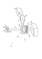
- the wind turbine generator 1 includes a wind turbine 11, a first rotation shaft 12, a shaft cover 13, a bearing 15, a power transmission unit 20, a generator 41, and a second rotation shaft 42.
- the wind turbine 11 is a vertical axis wind turbine which receives and rotates wind by an impeller, and the first rotation shaft 12 also rotates around the first rotation shaft 12 extending in the vertical direction.
- the first rotation shaft 12 extends in the vertical direction and is covered with a shaft cover 13 attached to a base 50.
- the shaft cover 13 and the base 50 rotate the first rotation shaft 12 via a bearing 15 such as a ball bearing. Hold freely.
- the power transmission unit 20 includes a first pulley 21 (tension adjustment device: drive pulley face 21a, drive pulley 21b, first weight roller 21c, first roller guide portion 21d), a friction conductive belt 31, and a second pulley 33.
- the rotational force of the first rotating shaft 12 obtained by the rotation of the wind turbine 11 is transmitted to the second rotating shaft 42 of the generator 41.
- the drive pulley face 21 a and the first roller guide portion 21 d are attached to the first rotation shaft 12.
- the first roller guide portion 21d is provided with a guide movable in the radial direction of the first rotation shaft 12, and the first weight roller 21c is placed on the guide.
- a mode in which two first weight rollers 21c are mounted on the first roller guide portion 21d will be described, but three or more first weight rollers 21c are mounted on the first roller guide portion 21d It may be in the form.
- the guide of the first roller guide portion 21 d has a low radial inner side (center) so that the first weight roller 21 c can be easily positioned near the radial inner side (center) when the number of rotations of the first rotation shaft 12 is low; It is desirable to provide an inclination (a truncated cone-shaped inclined surface with its center protruding downward, not shown) such that the radially outer side is high.
- the drive pulley 21 b is mounted on the first weight roller 21 c in a position facing the drive pulley face 21 a and movable in the axial direction of the first rotation shaft 12.
- the friction conductive belt 31 is hooked on the first pulley 21 (between the drive pulley face 21a and the drive pulley 21b) whose pulley diameter is variable on the drive side, and on the driven side is the second pulley 33 whose pulley diameter does not change. It is hung.
- At least one of the lower surface of the drive pulley face 21 a (the surface on which the friction conductive belt 31 is hung) and the upper surface of the drive pulley 21 b (the surface on which the friction conductive belt 31 is hung) is inclined (the first rotation shaft 12). Have a plane inclined from the vertical horizontal plane).
- the slope of the drive pulley face 21a has a truncated cone shape with the center projecting downward
- the slope of the drive pulley 21b has a truncated cone shape with the center projecting upward.
- the lower surface (the surface opposite to the side on which the friction conductive belt 31 is hung) of the drive pulley 21b has a slope substantially parallel to the top surface, and contacts the first weight roller 21c at the slope.
- the first weight roller 21c has a substantially cylindrical shape, and is placed between the drive pulley 21b and the guides of the first roller guide portion 21d.
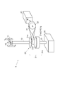
- the first weight roller 21c While the rotation speed of the first rotation shaft 12 is low, the first weight roller 21c is disposed at a position approaching the first rotation shaft 12 due to the weight of the drive pulley 21b and the tension of the friction conductive belt 31 (first state, 1 and 3).
- the first weight roller 21c When the number of rotations of the first rotation shaft 12 is low (the second state), the first weight roller 21c is rotated by the weight of the drive pulley 21b and the tension of the friction conductive belt 31 when the number of rotations decreases. Move to a position approaching 12 (first state, see FIGS. 1 and 3).
- the second pulley 33 on which the friction conductive belt 31 is hung is attached to the second rotation shaft 42 of the generator 41.
- the pulley diameter of the second pulley 33 does not change like the first pulley 21.
- the friction conductive belt 31 is made of rubber or the like and is a power transmission unit using a V-belt or the like, and is attached to the first pulley 21 and the second pulley 33 by cross attachment.
- the generator 41 generates electric power based on the rotation of the second rotation shaft 42, and supplies electric power to a storage battery (not shown) and an electric device (not shown) in the subsequent stage.
- the first weight roller 21c moves radially outward to move the drive pulley 21b based on the installation position (wind strength) of the wind turbine 11, the rotational performance of the wind turbine 11, the power generation capacity of the generator 41, etc.
- Specification of the drive pulley 21b tilt angle, size, etc.
- specification of the friction conductive belt 31 tension or size, etc.
- the drawing shows a structure in which the power transmission unit 20, the generator 41, and the second rotating shaft 42 are visible from the outside, they are covered to prevent deterioration of the respective constituent members and deterioration of the transmission efficiency due to wind and rain. It is desirable to provide a cover member.
- the use of the friction conductive belt 31 makes it possible to suppress the generation of vibration and noise as compared with a mode in which the rotation of the first rotation shaft 12 is directly transmitted coaxially to the generator 41. Further, by using the friction conductive belt 31, when the rotational speed of the first rotating shaft 12 changes rapidly due to the change of the wind power, it is possible to prevent the damage of the component such as the generator 41 by the slip.
- wind power generation can be performed using the generator 41 installed so that the second rotation shaft 42 is substantially parallel to the horizontal direction. Therefore, wind power generation can be performed using the generators 41 of various shapes and installation conditions (the installation freedom of the generators is high).
- the distance between the drive pulley face 21a and the drive pulley 21b is changed without using any other drive source.
- the tension of the friction conductive belt 31 can be changed.
- the tension of the friction conductive belt 31 is loosened to reduce the resistance due to the friction transmission belt 31 and the second rotation shaft 42, and the first rotation shaft 12 rotates.
- the tension of the friction conductive belt 31 can be increased to increase the power transmission efficiency to the second rotation shaft 42 (power generation efficiency can be increased).
- the specifications of the generator 41 (rotational resistance of the second rotation shaft 42, etc.) and the specifications (rotational ability) of the wind turbine 11 differ depending on the equipment used, but the tension adjustment device (in the first embodiment or the second embodiment 1) By adjusting the specifications (size and weight) of members constituting the 1 pulley 21, the second pulley 33 in the third embodiment, and the roller 32b in the fourth embodiment, the second rotation from the first rotation shaft 12 is performed. Adjustment can be made so that power transmission to the shaft 42 can be performed efficiently (for operation with high power generation efficiency). For this reason, various generators including the installation conditions can be used as the generator 41 of the wind turbine 1.
- the movement control of the drive pulley 21b in the vertical direction has been described based on the movement of the first weight roller 21c in the radial direction by the centrifugal force, but other means are used to control the movement of the drive pulley 21b in the vertical direction. Movement control may be performed.
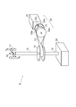
- the drive pulley 21b is vertically moved based on information from the first sensor 21e that measures the number of rotations of the first rotation shaft 12 and the first sensor 21e.
- a first actuator 21f that performs movement control of the direction is provided (see the second embodiment, FIG. 5).
- the first actuator 21 f positions the drive pulley 21 b downward so that the friction conductive belt 31 can be hung near the first rotation shaft 12 until the rotational speed of the first rotation shaft 12 exceeds the threshold, and the threshold is exceeded.
- the first actuator 21 f positions the drive pulley 21 b upward so that the friction conductive belt 31 can be hung at a position away from the first rotation shaft 12.
- the threshold value is not limited to one, and a plurality of threshold values may be provided to move the drive pulley 21 b in the vertical direction stepwise.
- the power required to drive the first sensor 21 e and the first actuator 21 f may be supplied from the outside, or the first electric power is generated based on the rotation of the first rotation shaft 12.
- a configuration may be adopted in which the first sensor 21e and the first actuator 21f are driven by providing the power generation device 21g and the power storage device and using the power supplied from the power generation device and the power storage device.
- the first power generation device 21g mentioned here is used only for driving the first sensor 21e and the first actuator 21f, and therefore may be smaller than the generator 41.
- the first actuator 21 f is driven (the first actuator 21 f is driven to push the drive pulley 21 b upward only when the rotational speed of the first rotary shaft 12 is high and the first actuator 21 f can be driven). It may be.
- the first pulley 21 on the drive side in order to adjust the tension of the friction conductive belt 31 a mode is described in which the distance between the pulley face and the pulley is variable.
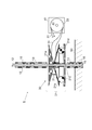
- the second pulley 33 on the driven side may be configured to vary the distance between the pulley face and the pulley (see the third embodiment, FIGS. 6 and 7).
- the second pulley 33 in the third embodiment has a driven pulley face 33a, a driven pulley 33b, a second weight roller 33c, and a second roller guide portion 33d as a tension adjustment device.
- the configuration other than the configuration of the first pulley 21 and the second pulley 33 is the same as that of the first embodiment.
- portions different from the first embodiment the configuration and operation of the first pulley 21 and the second pulley 33
- the pulley diameter of the first pulley 21 in the third embodiment does not change, and the pulley diameter of the second pulley 33 changes.
- the driven pulley face 33 a and the second roller guide portion 33 d are attached to the second rotation shaft 42.
- the second roller guide portion 33d is provided with a guide movable in the radial direction of the second rotation shaft 42, and the second weight roller 33c is placed between the guide and the driven pulley 33b.
- the guide of the second roller guide portion 33d has a radially inner (center) driven pulley so that the second weight roller 33c can be easily positioned near the inner side (center) in the radial direction when the rotation speed of the second rotation shaft 42 is low.
- the driven pulley 33 b is attached at a position facing the driven pulley face 33 a and movable in the axial direction of the second rotation shaft 42.
- the friction conductive belt 31 is hooked on the first pulley 21 whose pulley diameter does not change on the drive side, and the driven side is on the second pulley 33 (between the driven pulley face 33 a and the driven pulley 33 b) whose pulley diameter is variable. It is hung.
- At least one of the side surfaces of the driven pulley face 33a on which the friction conductive belt 31 is to be hung and the side surfaces of the driven pulley 33b on which the friction conductive belt 31 is to be hooked is sloped Face).
- the slope of the driven pulley face 33a has a frusto-conical shape in which the center protrudes in the direction approaching the driven pulley 33b, and the slope of the driven pulley 33b protrudes in the direction toward the center approaching the driven pulley face 33a It has a truncated cone shape.
- a side surface of the driven pulley 33b opposite to the side on which the friction conductive belt 31 is hung has a slope substantially parallel to the surface on which the friction conductive belt 31 is hung, and the second weight roller 33c is the slope I am in contact with
- the second weight roller 33c has a substantially cylindrical shape, and is placed between the driven pulley 33b and the guides of the second roller guide portion 33d.
- the second weight roller 33c moves radially outward in the second state based on the installation position (wind strength) of the wind turbine 11, the rotation performance of the wind turbine 11, the power generation capacity of the generator 41, etc.
- the second weight roller 33c is disposed at a position approaching the second rotation shaft 42 by the tension of the belt 31 (first state, see FIG. 6).
- the driven pulley face 33a and the driven pulley 33b are separated, and the friction conductive belt 31 is at a position close to the second rotation shaft 42, and the tension of the friction conductive belt 31 becomes looser than the second state described later. .
- the driven pulley 33 b is pushed up, the distance between the driven pulley face 33 a and the driven pulley 33 b is narrowed, and the friction conductive belt 31 moves to a position far from the second rotation shaft 42. It is higher than 1 state.
- the second weight roller 33c When the rotational speed becomes low from the state where the rotational speed of the first rotation shaft 12 is high (the second state), the second weight roller 33c is inclined by the inclination of the guide of the second roller guide portion 33d and the tension of the friction conductive belt 31. , Moves to a position approaching the second rotation shaft 42 (first state, see FIG. 6).
- the tension of the friction conductive belt 31 can be adjusted to be loose when the number of rotations is low and to be strong when the number of rotations is high.
- the number of rotations of the first rotation shaft 12 is predicted from the amount of air
- a second actuator 32 c that presses or separates the roller 32 b contacting the friction conductive belt 31 against the friction conductive belt 31 (changes the degree of contact with the friction conductive belt 31), and the tension of the friction conductive belt 31
- the power required to drive the second sensor 32a and the second actuator 32c may be supplied from the outside, or the second power generation is performed based on the rotation of the first rotation shaft 12.
- the second sensor 32a or the second actuator 32c may be driven by providing the power generation device 32d or the power storage device, and using the power supplied from the power generation device or the power storage device.
- the second power generation device 32 d mentioned here is used only for driving the second sensor 32 a and the second actuator 32 c, and therefore may be smaller than the generator 41.
- the rotation speed of the first rotating shaft 12 is high, so according to the power generated by the second power generation device 32d without providing the power storage device or the second sensor 32a (
- the second actuator 32c is driven only when the second actuator 32b can be driven according to the rotation state of the first rotary shaft 12 (when the rotational speed of the first rotary shaft 12 is high and the second actuator 32c can be driven).
- the roller 32b may be pressed against the friction conductive belt 31 to increase the tension of the friction electric belt 31).
Landscapes
- Engineering & Computer Science (AREA)
- Life Sciences & Earth Sciences (AREA)
- Sustainable Development (AREA)
- Sustainable Energy (AREA)
- Chemical & Material Sciences (AREA)
- Combustion & Propulsion (AREA)
- Mechanical Engineering (AREA)
- General Engineering & Computer Science (AREA)
- Power Engineering (AREA)
- Wind Motors (AREA)
Abstract
【課題】 垂直軸風車を使った風力発電装置において、発電機の設置自由度が高いものを提供する。 【解決手段】 風力発電装置1は、鉛直方向に第1回転軸12を有する風車11を備える。第2回転軸42を有し、第1回転軸12の回転力に基づいて、第2回転軸42を回転させて、電力を発生させる発電機41を備える。第1回転軸12に取り付けられた第1プーリー21と、第2回転軸42に取り付けられた第2プーリー33と、第1プーリー21と第2プーリー33に掛けられ十字掛けベルトで構成された摩擦伝導ベルト31とを有し、第1回転軸12の回転力を第2回転軸42に伝達する動力伝達機構20を備える。第2回転軸42は、第1回転軸12とねじれの位置関係にある。
Description
本発明は、風力発電装置に関する。
従来、特許文献1のように、垂直軸風車を含む風力発電装置が提案されている。
しかし、風車の回転軸と、発電機の回転軸が平行に配置されるため、鉛直方向に延びる回転軸を有する発電機に限定され、設置の自由度が低い。
したがって本発明の目的は、垂直軸風車を使った風力発電装置において、発電機の設置自由度が高いものを提供することである。
本発明に係る風力発電装置は、鉛直方向に第1回転軸を有する風車と、第2回転軸を有し、第1回転軸の回転力に基づいて、第2回転軸を回転させて、電力を発生させる発電機と、第1回転軸に取り付けられた第1プーリーと、第2回転軸に取り付けられた第2プーリーと、第1プーリーと第2プーリーに掛けられ十字掛けベルトで構成された摩擦伝導ベルトとを有し、第1回転軸の回転力を第2回転軸に伝達する動力伝達機構とを備え、第2回転軸は、第1回転軸とねじれの位置関係にある。
摩擦伝導ベルトを使うことにより、第1回転軸の回転を同軸で直接的に発電機に伝達する形態に比べて、振動や騒音の発生を抑えることが可能になる。また、摩擦伝導ベルトを使うことにより、風力の変化により第1回転軸の回転数が急激に変化した場合に、スリップで発電機などの構成部品の損傷を防ぐことが出来る。
また、摩擦伝導ベルトを十字掛けにすることにより、第2回転軸が、第1回転軸と平行で無く、ねじれの位置関係にある場合でも、摩擦伝導ベルトを介して、動力伝達を行うこと出来る。特に、第2回転軸が水平方向に略平行になるように設置された発電機を使って、風力発電を行うことが出来る。従って、様々な形状や設置条件の発電機を使って、風力発電を行うことが出来る(発電機の設置自由度が高い)。
好ましくは、動力伝達機構は、第1回転軸の回転数に応じて、摩擦伝導ベルトの張力を調整する張力調整装置を有する。
第1回転軸の回転数が少ない状態では、摩擦伝導ベルトの張力を緩めて、摩擦伝導ベルトや第2回転軸による抵抗を少なくして、第1回転軸が回転しやすくし、第1回転軸の回転数が多い状態では、摩擦伝導ベルトの張力を高めて、第2回転軸への動力伝達効率を高める(発電効率を高める)ことが出来る。
風が強い状態から風が弱い状態に変わった時に、摩擦伝導ベルトや第2回転軸による抵抗(負荷)が少なくなるので、風車の回転が止まらずに回転を維持しやすくなる。回転を維持出来た場合には、回転が止まった場合に比べて、次に風が吹いた時に風車の回転を加速させて発電を行いやすくなるメリットがある。
発電機の仕様(第2回転軸の回転抵抗など)や、風車の仕様(回転能力)は、使用する機材によって異なるが、張力調整装置を構成する部材の仕様(大きさや重さ)を調整することで、第1回転軸から第2回転軸への動力伝達が効率良く行えるよう(高い発電効率で運用出来るよう)に調整出来る。このため、設置条件を含めて様々な発電機を風力発電装置の発電機として使用することが出来る。
さらに好ましくは、第1プーリーが前記張力調整装置であり、第1プーリーは、ドライブプーリーフェイスと、ドライブプーリーフェイスと対向するドライブプーリーとを有し、ドライブプーリーが鉛直方向に移動制御されることで、ドライブプーリーフェイスとドライブプーリーとの距離が変動し、摩擦伝導ベルトの張力が変動する。
さらに好ましくは、第1プーリーは、第1回転軸の半径方向に移動可能で、半径方向外側に移動した時にドライブプーリーを押し上げるウエイトローラーと、ウエイトローラーが載置されるローラーガイド部を有する。
また、ドライブプーリーの上下方向の移動を遠心力によるウエイトローラーを移動に基づいて行わせるため、他の駆動源を用いずに、ドライブプーリーフェイスとドライブプーリーの距離を変えて、摩擦伝導ベルトの張力を変化させることが出来る。
また、好ましくは、第1プーリーは、第1回転軸の回転数に基づいて、ドライブプーリーを鉛直方向に移動させる第1アクチュエータを有する。
また、好ましくは、第2プーリーが張力調整装置であり、第2プーリーは、ドリブンプーリーフェイスと、ドリブンプーリーフェイスと対向するドリブンプーリーとを有し、ドリブンプーリーが、第2回転軸方向に移動制御されることで、ドリブンプーリーフェイスとドリブンプーリーとの距離が変動し、摩擦伝導ベルトの張力が変動する。
被動側のプーリー(第2プーリー)を可変プーリーとすることでも、摩擦伝導ベルトの張力を回転数が低い時は緩く、回転数が高い時は強くするように調整することが出来る。
また、好ましくは、張力調整装置は、摩擦伝導ベルトに接触するローラーと、第1回転軸の回転状態に応じて、ローラーを移動させて摩擦伝導ベルトとの接触度合いを変化させる第2アクチュエータを有する。
以上のように本発明によれば、垂直軸風車を使った風力発電装置において、発電機の設置自由度が高いものを提供することができる。
以下、第1実施形態について、図を用いて説明する(図1~図4参照)。第1実施形態における風力発電装置1は、風車11、第1回転軸12、シャフトカバー13、軸受け15、動力伝達部20、発電機41、第2回転軸42を備える。
風車11は、風を羽根車で受けて回転する垂直軸風車で、鉛直方向に延びる第1回転軸12を中心にして、第1回転軸12も一緒に回転する。
第1回転軸12は、鉛直方向に延び、土台50に取り付けられたシャフトカバー13で覆われ、シャフトカバー13や土台50が、ボールベアリングなどの軸受け15を介して、第1回転軸12を回転自在な状態で保持する。
動力伝達部20は、第1プーリー21(張力調整装置:ドライブプーリーフェイス21a、ドライブプーリー21b、第1ウエイトローラー21c、第1ローラーガイド部21d)、摩擦伝導ベルト31、第2プーリー33を有し、風車11の回転により得られた第1回転軸12の回転力を、発電機41の第2回転軸42に伝達する。
第1回転軸12には、ドライブプーリーフェイス21aと第1ローラーガイド部21dが取り付けられる。
第1ローラーガイド部21dには、第1回転軸12の半径方向に移動可能なガイドが設けられ、当該ガイド上に第1ウエイトローラー21cが載置される。第1実施形態では、2つの第1ウエイトローラー21cが第1ローラーガイド部21dに載置される形態を説明するが、3つ以上の第1ウエイトローラー21cが第1ローラーガイド部21dに載置される形態であってもよい。
第1ローラーガイド部21dのガイドは、第1回転軸12の回転数が低い時に、第1ウエイトローラー21cが半径方向内側(中心)近くに位置しやすいように、半径方向内側(中心)が低く、半径方向外側が高くなるような傾斜(中央が下側に突出する円錐台形状の傾斜面、不図示)が設けられるのが望ましい。
ドライブプーリーフェイス21aと対向する位置であって、第1回転軸12の軸方向に移動可能な状態で、ドライブプーリー21bが、第1ウエイトローラー21cに載置される。
摩擦伝導ベルト31は、駆動側は、プーリー径が可変である第1プーリー21(ドライブプーリーフェイス21aとドライブプーリー21bの間)に掛けられ、被動側は、プーリー径が変わらない第2プーリー33に掛けられる。
ドライブプーリーフェイス21aの下面(摩擦伝導ベルト31が掛けられる側の面)と、ドライブプーリー21bの上面(摩擦伝導ベルト31が掛けられる側の面)は、少なくとも一方が斜面(第1回転軸12に垂直な水平面から傾いた面)を有する。
具体的には、ドライブプーリーフェイス21aの斜面は、中央が下側に突出する円錐台形状を有し、ドライブプーリー21bの斜面は、中央が上側に突出する円錐台形状を有する。
第1実施形態では、ドライブプーリーフェイス21aの下面と、ドライブプーリー21bの上面の両方が斜面を有する形態を説明する。
ドライブプーリー21bの下面(摩擦伝導ベルト31が掛けられる側と反対側の面)は、上面と略平行な斜面を有し、当該斜面で、第1ウエイトローラー21cと接する。
第1ウエイトローラー21cは、略円柱形状を有し、ドライブプーリー21bと第1ローラーガイド部21dのガイドの間に載置される。
第1回転軸12の回転数が低い間は、ドライブプーリー21bの自重や摩擦伝導ベルト31の張力により、第1ウエイトローラー21cは、第1回転軸12に近づく位置に配置される(第1状態、図1、図3参照)。
この場合、ドライブプーリーフェイス21aとドライブプーリー21bが離れていて、摩擦伝導ベルト31は、第1回転軸12に近い位置にあって、摩擦伝導ベルト31の張力は後述する第2状態よりも緩くなる。
第1回転軸12の回転数が高くなると、第1ウエイトローラー21cは遠心力で第1回転軸12から遠ざかる位置に移動する(第2状態、図2、図4参照)。
これにより、ドライブプーリー21bが押し上げられ、ドライブプーリーフェイス21aとドライブプーリー21bの距離が狭められ、摩擦伝導ベルト31は、第1回転軸12から遠い位置に移動し、摩擦伝導ベルト31の張力は第1状態よりも高くなる。
第1回転軸12の回転数が高い状態(第2状態)から、回転数が低い状態になると、ドライブプーリー21bの自重や摩擦伝導ベルト31の張力により、第1ウエイトローラー21cは、第1回転軸12に近づく位置に移動する(第1状態、図1、図3参照)。
摩擦伝導ベルト31が掛けられる第2プーリー33は、発電機41の第2回転軸42に取り付けられる。第1実施形態では、第2プーリー33は、第1プーリー21のようにプーリー径が変化しない。
摩擦伝導ベルト31は、ゴムなどで構成され、Vベルトなどを使った動力伝達手段であり、十字掛けで、第1プーリー21や第2プーリー33に取り付けられる。
発電機41は、第2回転軸42の回転に基づいて、電力を発生させ、後段の蓄電池(不図示)や電気機器(不図示)に電力を供給する。
風車11の設置位置(風の強さ)、風車11の回転性能、発電機41の発電能力などに基づき、第2状態の時に、第1ウエイトローラー21cが半径方向外側に移動し、ドライブプーリー21bを上方向に移動させ、摩擦伝導ベルト31を第1回転軸12から離れる方向に移動させられるように、ドライブプーリー21bの仕様(傾斜角や大きさなど)、摩擦伝導ベルト31の仕様(張力や大きさなど)、第1ウエイトローラー21cの仕様(重さなど)が決定されるのが望ましい。
なお、図面では、動力伝達部20、発電機41、第2回転軸42が外部から見える構造を示しているが、風雨による各構成部材の劣化や伝達効率の低下を防止するため、これらを覆うカバー部材を設けるのが望ましい。
摩擦伝導ベルト31を使うことにより、第1回転軸12の回転を同軸で直接的に発電機41に伝達する形態に比べて、振動や騒音の発生を抑えることが可能になる。また、摩擦伝導ベルト31を使うことにより、風力の変化により第1回転軸12の回転数が急激に変化した場合に、スリップで発電機41などの構成部品の損傷を防ぐことが出来る。
また、摩擦伝導ベルト31を十字掛けにすることにより、第2回転軸42が、第1回転軸12と平行で無く、ねじれの位置関係にある場合でも、摩擦伝導ベルト31を介して、動力伝達を行うこと出来る。特に、第2回転軸42が水平方向に略平行になるように設置された発電機41を使って、風力発電を行うことが出来る。従って、様々な形状や設置条件の発電機41を使って、風力発電を行うことが出来る(発電機の設置自由度が高い)。
また、ドライブプーリー21bの上下方向の移動を遠心力による第1ウエイトローラー21cを移動に基づいて行わせるため、他の駆動源を用いずに、ドライブプーリーフェイス21aとドライブプーリー21bの距離を変えて、摩擦伝導ベルト31の張力を変化させることが出来る。
第1回転軸12の回転数が少ない第1状態では、摩擦伝導ベルト31の張力を緩めて、摩擦伝導ベルト31や第2回転軸42による抵抗を少なくして、第1回転軸12が回転しやすくし、第1回転軸12の回転数が多い第2状態では、摩擦伝導ベルト31の張力を高めて、第2回転軸42への動力伝達効率を高める(発電効率を高める)ことが出来る。
風が強い状態から風が弱い状態に変わった時に、摩擦伝導ベルト31や第2回転軸42による抵抗(負荷)が少なくなるので、風車11の回転が止まらずに回転を維持しやすくなる。回転を維持出来た場合には、回転が止まった場合に比べて、次に風が吹いた時に風車の回転を加速させて発電を行いやすくなるメリットがある。
発電機41の仕様(第2回転軸42の回転抵抗など)や、風車11の仕様(回転能力)は、使用する機材によって異なるが、張力調整装置(第1実施形態や第2実施形態では第1プーリー21、第3実施形態では第2プーリー33、第4実施形態ではローラー32bなど)を構成する部材の仕様(大きさや重さ)を調整することで、第1回転軸12から第2回転軸42への動力伝達が効率良く行えるよう(高い発電効率で運用出来るよう)に調整出来る。このため、設置条件を含めて様々な発電機を風力発電装置1の発電機41として使用することが出来る。
第1実施形態では、ドライブプーリー21bの上下方向の移動制御を遠心力による第1ウエイトローラー21cの半径方向の移動に基づいて行わせる形態を説明したが、他の手段によってドライブプーリー21bの上下方向の移動制御を行っても良い。
例えば、第1ウエイトローラー21cと第1ローラーガイド部21dに代えて、第1回転軸12の回転数を計測する第1センサ21eと、第1センサ21eからの情報に基づいて、ドライブプーリー21bを上下方向の移動制御を行う第1アクチュエータ21fとを設ける形態が考えられる(第2実施形態、図5参照)。
第1回転軸12の回転数が閾値を超えるまでは、摩擦伝導ベルト31が第1回転軸12の近くに掛けられるように、第1アクチュエータ21fがドライブプーリー21bを下方に位置させ、閾値を超えると、摩擦伝導ベルト31が第1回転軸12から離れた位置で掛けられるように、第1アクチュエータ21fがドライブプーリー21bを上方に位置させる。
閾値は1つだけに限定せず、複数の閾値を設け、段階的にドライブプーリー21bを上下方向に移動させる形態であってもよい。
第2実施形態では、第1センサ21eや第1アクチュエータ21fの駆動に必要な電力が、外部から供給される形態であってもよいし、第1回転軸12の回転に基づいて発電する第1発電装置21gや蓄電装置を設けて、当該発電装置や当該蓄電装置から供給される電力で、第1センサ21eや第1アクチュエータ21fを駆動する形態であってもよい。ここでいう第1発電装置21gは、第1センサ21eや第1アクチュエータ21fを駆動するためだけに使用されるため、発電機41に比べて小型のもので良い。
第1発電装置21gが発電する時は、第1回転軸12の回転数が高い時なので、蓄電装置や、第1センサ21eを設けずに、第1発電装置21gで発電した電力に応じて、第1アクチュエータ21fを駆動する(第1回転軸12の回転数が高くて、第1アクチュエータ21fを駆動出来る時だけ、第1アクチュエータ21fを駆動して、ドライブプーリー21bを上方向に押し上げる)形態であってもよい。
また、第1実施形態や第2実施形態では、摩擦伝導ベルト31の張力を調整する為に駆動側の第1プーリー21について、プーリーフェイスとプーリーとの間を可変にする形態を説明したが、被動側の第2プーリー33について、プーリーフェイスとプーリーとの間を可変にする形態であってもよい(第3実施形態、図6、図7参照)。
第3実施形態における第2プーリー33は、張力調整装置として、ドリブンプーリーフェイス33aとドリブンプーリー33bと第2ウエイトローラー33cと第2ローラーガイド部33dを有する。第1プーリー21と第2プーリー33の構成以外は、第1実施形態と同じである。以下、第1実施形態と異なる部分(第1プーリー21や第2プーリー33の構成や、動作)について説明する。
第3実施形態における第1プーリー21は、プーリー径が変化せず、第2プーリー33は、プーリー径が変化する。
第2回転軸42には、ドリブンプーリーフェイス33aと第2ローラーガイド部33dが取り付けられる。
第2ローラーガイド部33dには、第2回転軸42の半径方向に移動可能なガイドが設けられ、当該ガイドとドリブンプーリー33bの間に第2ウエイトローラー33cが載置される。
第2ローラーガイド部33dのガイドは、第2回転軸42の回転数が低い時に、第2ウエイトローラー33cが半径方向内側(中心)近くに位置しやすいように、半径方向内側(中心)がドリブンプーリー33bから離れ、半径方向外側がドリブンプーリー33bに近くなるような傾斜(中央がドリブンプーリー33bから離れる方向に突出する円錐台形状の傾斜面)が設けられる。
ドリブンプーリーフェイス33aと対向する位置であって、第2回転軸42の軸方向に移動可能な状態で、ドリブンプーリー33bが、取り付けられる。
摩擦伝導ベルト31は、駆動側は、プーリー径が変わらない第1プーリー21に掛けられ、被動側は、プーリー径が可変である第2プーリー33(ドリブンプーリーフェイス33aとドリブンプーリー33bの間)に掛けられる。
ドリブンプーリーフェイス33aの側面であって摩擦伝導ベルト31が掛けられる側の面と、ドリブンプーリー33bの側面であって摩擦伝導ベルト31が掛けられる側の面は、少なくとも一方が斜面(水平面から傾いた面)を有する。
具体的には、ドリブンプーリーフェイス33aの斜面は、中央がドリブンプーリー33bに近づく方向に突出する円錐台形状を有し、ドリブンプーリー33bの斜面は、中央がドリブンプーリーフェイス33aに近づく方向に突出する円錐台形状を有する。
第3実施形態では、ドリブンプーリーフェイス33aの側面と、ドリブンプーリー33bの側面の両方が斜面を有する形態を説明する。
ドリブンプーリー33bの側面であって摩擦伝導ベルト31が掛けられる側と反対側の面は、摩擦伝導ベルト31が掛けられる側の面と略平行な斜面を有し、当該斜面で、第2ウエイトローラー33cと接する。
第2ウエイトローラー33cは、略円柱形状を有し、ドリブンプーリー33bと、第2ローラーガイド部33dのガイドの間に載置される。
風車11の設置位置(風の強さ)、風車11の回転性能、発電機41の発電能力などに基づき、第2状態の時に、第2ウエイトローラー33cが半径方向外側に移動し、ドリブンプーリー33bをドリブンプーリーフェイス33aに近づく方向に移動させ、摩擦伝導ベルト31を第2回転軸42から離れる方向に移動させられるように、ドリブンプーリー33bの仕様(傾斜角や大きさなど)、摩擦伝導ベルト31の仕様(張力や大きさなど)、第2ウエイトローラー33cの仕様(重さなど)が決定されるのが望ましい。
第1回転軸12の回転数が低い間は、摩擦伝導ベルト31を介して回転力が伝達された第2回転軸42の回転数も低く、第2ローラーガイド部33dのガイドの傾斜や摩擦伝導ベルト31の張力により、第2ウエイトローラー33cは、第2回転軸42に近づく位置に配置される(第1状態、図6参照)。
この場合、ドリブンプーリーフェイス33aとドリブンプーリー33bは離れていて、摩擦伝導ベルト31は、第2回転軸42に近い位置にあって、摩擦伝導ベルト31の張力は後述する第2状態よりも緩くなる。
第1回転軸12の回転数が高くなると、第2回転軸42の回転数も高くなり、第2ウエイトローラー33cは遠心力で第2回転軸42から遠ざかる位置に移動する(第2状態、図7参照)。
これにより、ドリブンプーリー33bが押し上げられ、ドリブンプーリーフェイス33aとドリブンプーリー33bの距離が狭められ、摩擦伝導ベルト31は、第2回転軸42から遠い位置に移動し、摩擦伝導ベルト31の張力は第1状態よりも高くなる。
第1回転軸12の回転数が高い状態(第2状態)から、回転数が低い状態になると、第2ローラーガイド部33dのガイドの傾斜や摩擦伝導ベルト31の張力により、第2ウエイトローラー33cは、第2回転軸42に近づく位置に移動する(第1状態、図6参照)。
被動側のプーリー(第2プーリー)を可変プーリーとすることでも、摩擦伝導ベルト31の張力を回転数が低い時は緩く、回転数が高い時は強くするように調整することが出来る。
第1実施形態~第3実施形態では、可変プーリーを用いて、摩擦伝導ベルト31の張力を調整する形態を説明したが、他の手段を用いて摩擦伝導ベルト31の張力を調整する形態であってもよい。
例えば、第1回転軸12の回転数、若しくは風車11を回転させる風量を計測する第2センサ32aと、第2センサ32aからの情報に基づいて(風量から第1回転軸12の回転数を予測して)、摩擦伝導ベルト31に接触するローラー32bを摩擦伝導ベルト31に押しつけたり離したりする(摩擦伝導ベルト31への接触度合いを変化させる)第2アクチュエータ32cを設け、摩擦伝導ベルト31の張力を緩めたり強めたりする形態が考えられる(第4実施形態、図8参照)。
第4実施形態では、第2センサ32aや第2アクチュエータ32cの駆動に必要な電力が、外部から供給される形態であってもよいし、第1回転軸12の回転に基づいて発電する第2発電装置32dや蓄電装置を設けて、当該発電装置や当該蓄電装置から供給される電力で、第2センサ32aや第2アクチュエータ32cを駆動する形態であってもよい。ここでいう第2発電装置32dは、第2センサ32aや第2アクチュエータ32cを駆動するためだけに使用されるため、発電機41に比べて小型のもので良い。
第2発電装置32dが発電する時は、第1回転軸12の回転数が高い時なので、蓄電装置や、第2センサ32aを設けずに、第2発電装置32dで発電した電力に応じて(第1回転軸12の回転状態に応じて)、第2アクチュエータ32bを駆動する(第1回転軸12の回転数が高くて、第2アクチュエータ32cを駆動出来る時だけ、第2アクチュエータ32cを駆動して、ローラー32bを摩擦伝導ベルト31に押しつけて摩擦電動ベルト31の張力を強める)形態であってもよい。
1 風力発電装置
11 風車
12 第1回転軸
13 シャフトカバー
15 軸受け
20 動力伝達部
21 第1プーリー
21a ドライブプーリーフェイス
21b ドライブプーリー
21c 第1ウエイトローラー
21d 第1ローラーガイド部
21e 第1センサ
21f 第1アクチュエータ
31 摩擦伝導ベルト
32a 第2センサ
32b ローラー
32c 第2アクチュエータ
32d 第2発電装置
33 第2プーリー
33a ドリブンプーリーフェイス
33b ドリブンプーリー
33c 第2ウエイトローラー
33d 第2ローラーガイド部
41 発電機
42 第2回転軸
50 土台
11 風車
12 第1回転軸
13 シャフトカバー
15 軸受け
20 動力伝達部
21 第1プーリー
21a ドライブプーリーフェイス
21b ドライブプーリー
21c 第1ウエイトローラー
21d 第1ローラーガイド部
21e 第1センサ
21f 第1アクチュエータ
31 摩擦伝導ベルト
32a 第2センサ
32b ローラー
32c 第2アクチュエータ
32d 第2発電装置
33 第2プーリー
33a ドリブンプーリーフェイス
33b ドリブンプーリー
33c 第2ウエイトローラー
33d 第2ローラーガイド部
41 発電機
42 第2回転軸
50 土台
Claims (7)
- 鉛直方向に第1回転軸を有する風車と、
第2回転軸を有し、前記第1回転軸の回転力に基づいて、前記第2回転軸を回転させて、電力を発生させる発電機と、
前記第1回転軸に取り付けられた第1プーリーと、前記第2回転軸に取り付けられた第2プーリーと、前記第1プーリーと前記第2プーリーに掛けられ十字掛けベルトで構成された摩擦伝導ベルトとを有し、前記第1回転軸の回転力を前記第2回転軸に伝達する動力伝達機構とを備え、
前記第2回転軸は、前記第1回転軸とねじれの位置関係にあることを特徴とする風力発電装置。 - 前記動力伝達機構は、前記第1回転軸の回転数に応じて、前記摩擦伝導ベルトの張力を調整する張力調整装置を有することを特徴とする請求項1に記載の風力発電装置。
- 前記第1プーリーが前記張力調整装置であり、
前記第1プーリーは、ドライブプーリーフェイスと、前記ドライブプーリーフェイスと対向するドライブプーリーとを有し、
前記ドライブプーリーが鉛直方向に移動制御されることで、前記ドライブプーリーフェイスと前記ドライブプーリーとの距離が変動し、前記摩擦伝導ベルトの張力が変動することを特徴とする請求項2に記載の風力発電装置。 - 前記第1プーリーは、前記第1回転軸の半径方向に移動可能で、半径方向外側に移動した時に前記ドライブプーリーを押し上げるウエイトローラーと、前記ウエイトローラーが載置されるローラーガイド部を有することを特徴とする請求項3に記載の風力発電装置。
- 前記第1プーリーは、前記第1回転軸の回転数に基づいて、前記ドライブプーリーを鉛直方向に移動させる第1アクチュエータを有することを特徴とする請求項3に記載の風力発電装置。
- 前記第2プーリーが前記張力調整装置であり、
前記第2プーリーは、ドリブンプーリーフェイスと、前記ドリブンプーリーフェイスと対向するドリブンプーリーとを有し、
前記ドリブンプーリーが、前記第2回転軸方向に移動制御されることで、前記ドリブンプーリーフェイスと前記ドリブンプーリーとの距離が変動し、前記摩擦伝導ベルトの張力が変動することを特徴とする請求項2に記載の風力発電装置。 - 前記張力調整装置は、前記摩擦伝導ベルトに接触するローラーと、前記第1回転軸の回転状態に応じて、前記ローラーを移動させて前記摩擦伝導ベルトとの接触度合いを変化させる第2アクチュエータを有することを特徴とする請求項2に記載の風力発電装置。
Priority Applications (3)
| Application Number | Priority Date | Filing Date | Title |
|---|---|---|---|
| PCT/JP2013/004765 WO2015019384A1 (ja) | 2013-08-07 | 2013-08-07 | 風力発電装置 |
| JP2013557952A JP5557966B1 (ja) | 2013-08-07 | 2013-08-07 | 風力発電装置 |
| TW103126799A TWI551796B (zh) | 2013-08-07 | 2014-08-05 | 風力發電裝置 |
Applications Claiming Priority (1)
| Application Number | Priority Date | Filing Date | Title |
|---|---|---|---|
| PCT/JP2013/004765 WO2015019384A1 (ja) | 2013-08-07 | 2013-08-07 | 風力発電装置 |
Publications (1)
| Publication Number | Publication Date |
|---|---|
| WO2015019384A1 true WO2015019384A1 (ja) | 2015-02-12 |
Family
ID=51416931
Family Applications (1)
| Application Number | Title | Priority Date | Filing Date |
|---|---|---|---|
| PCT/JP2013/004765 WO2015019384A1 (ja) | 2013-08-07 | 2013-08-07 | 風力発電装置 |
Country Status (3)
| Country | Link |
|---|---|
| JP (1) | JP5557966B1 (ja) |
| TW (1) | TWI551796B (ja) |
| WO (1) | WO2015019384A1 (ja) |
Families Citing this family (2)
| Publication number | Priority date | Publication date | Assignee | Title |
|---|---|---|---|---|
| WO2018109776A1 (en) * | 2016-12-12 | 2018-06-21 | S v vijay | Design and fabrication of advanced vertical axis wind turbine with self-alignment blades |
| FR3081191B1 (fr) * | 2018-05-18 | 2020-06-05 | Centre National De La Recherche Scientifique | Eolienne rabattable a axe vertical |
Citations (6)
| Publication number | Priority date | Publication date | Assignee | Title |
|---|---|---|---|---|
| JP2002188559A (ja) * | 2000-12-18 | 2002-07-05 | Koji Iizuka | 抗力型集合風車 |
| JP2003056451A (ja) * | 2001-08-20 | 2003-02-26 | Seiko Epson Corp | 風車発電装置 |
| JP2003284393A (ja) * | 2002-03-20 | 2003-10-03 | Denso Corp | 風力発電装置 |
| JP2003293940A (ja) * | 2002-04-01 | 2003-10-15 | Tomoji Oikawa | 簡易風力発電装置 |
| JP2005516159A (ja) * | 2002-01-25 | 2005-06-02 | ウィンド・ハーベスト・カンパニー | 結合渦垂直軸風力タービン |
| JP2007113560A (ja) * | 2005-09-20 | 2007-05-10 | Kanzaki Kokyukoki Mfg Co Ltd | 風力発電装置 |
Family Cites Families (2)
| Publication number | Priority date | Publication date | Assignee | Title |
|---|---|---|---|---|
| EP1640606A4 (en) * | 2003-06-09 | 2012-02-29 | Sinfonia Technology Co Ltd | VERTICAL AXIS TYPE WIND POWER GENERATION DEVICE AND METHOD FOR PRODUCING BLADES, STRUCTURE AND METHOD FOR INSTALLING A BLADE WHEEL FOR A WIND POWER GENERATION DEVICE, AND A WIND POWER GENERATION PLANT FOR WIND PROTECTION |
| JP2009101514A (ja) * | 2006-02-08 | 2009-05-14 | Hirotake Kasuya | シート状素材の張設具 |
-
2013
- 2013-08-07 WO PCT/JP2013/004765 patent/WO2015019384A1/ja active Application Filing
- 2013-08-07 JP JP2013557952A patent/JP5557966B1/ja active Active
-
2014
- 2014-08-05 TW TW103126799A patent/TWI551796B/zh active
Patent Citations (6)
| Publication number | Priority date | Publication date | Assignee | Title |
|---|---|---|---|---|
| JP2002188559A (ja) * | 2000-12-18 | 2002-07-05 | Koji Iizuka | 抗力型集合風車 |
| JP2003056451A (ja) * | 2001-08-20 | 2003-02-26 | Seiko Epson Corp | 風車発電装置 |
| JP2005516159A (ja) * | 2002-01-25 | 2005-06-02 | ウィンド・ハーベスト・カンパニー | 結合渦垂直軸風力タービン |
| JP2003284393A (ja) * | 2002-03-20 | 2003-10-03 | Denso Corp | 風力発電装置 |
| JP2003293940A (ja) * | 2002-04-01 | 2003-10-15 | Tomoji Oikawa | 簡易風力発電装置 |
| JP2007113560A (ja) * | 2005-09-20 | 2007-05-10 | Kanzaki Kokyukoki Mfg Co Ltd | 風力発電装置 |
Also Published As
| Publication number | Publication date |
|---|---|
| JPWO2015019384A1 (ja) | 2017-03-02 |
| JP5557966B1 (ja) | 2014-07-23 |
| TW201516247A (zh) | 2015-05-01 |
| TWI551796B (zh) | 2016-10-01 |
Similar Documents
| Publication | Publication Date | Title |
|---|---|---|
| CN101874159B (zh) | 抑制风轮机振动的方法 | |
| CN1982699A (zh) | 根据转速用于风力装置的转矩和节距控制的方法 | |
| EP3168460B1 (en) | Apparatus and method for controlling wind power generator unit | |
| EP2604852A2 (en) | Apparatus for generating electric power from wind energy | |
| KR20120027335A (ko) | 수직형 풍력 발전기 | |
| WO2015019384A1 (ja) | 風力発電装置 | |
| JP5669847B2 (ja) | ケーブル用もつれ防止機能付動力伝達ガイドシステム | |
| US9236779B2 (en) | Rotation maintaining device | |
| KR101285545B1 (ko) | 이중동력전달방식의 풍력발전시스템 | |
| KR101871944B1 (ko) | 베인 장치 | |
| KR101379455B1 (ko) | 풍력발전기의 로터 | |
| JP5619123B2 (ja) | 風車及び風力発電装置 | |
| KR101249438B1 (ko) | 수직축 풍력발전기 | |
| US20130028737A1 (en) | Adjustable wind turbine generating device | |
| EP2245313A1 (en) | Device for changing a pitch of a blade of an impeller/propeller and a fan comprising the device | |
| KR101548690B1 (ko) | 원심력에 의해 이동되는 이동부를 포함하는 풍력발전기의 블레이드 경사각 조절장치 | |
| JP5705139B2 (ja) | 風力発電装置 | |
| WO2016096726A1 (en) | Pulley for elevators | |
| KR102096568B1 (ko) | 실외기 바람을 이용하는 발전장치 | |
| KR101060327B1 (ko) | 회전몸체의 회전이 용이한 풍력발전기 | |
| KR20110130232A (ko) | 풍력발전기용 수직축 터어빈 | |
| KR101531266B1 (ko) | 오일 공급 장치 | |
| KR101120576B1 (ko) | 풍력 발전장치 | |
| JP5808696B2 (ja) | 風力発電装置 | |
| KR101406517B1 (ko) | 차량용 변속 조작기구 |
Legal Events
| Date | Code | Title | Description |
|---|---|---|---|
| ENP | Entry into the national phase |
Ref document number: 2013557952 Country of ref document: JP Kind code of ref document: A |
|
| 121 | Ep: the epo has been informed by wipo that ep was designated in this application |
Ref document number: 13891025 Country of ref document: EP Kind code of ref document: A1 |
|
| NENP | Non-entry into the national phase |
Ref country code: DE |
|
| 122 | Ep: pct application non-entry in european phase |
Ref document number: 13891025 Country of ref document: EP Kind code of ref document: A1 |