WO2015016067A1 - アンテナ装置 - Google Patents
アンテナ装置 Download PDFInfo
- Publication number
- WO2015016067A1 WO2015016067A1 PCT/JP2014/068926 JP2014068926W WO2015016067A1 WO 2015016067 A1 WO2015016067 A1 WO 2015016067A1 JP 2014068926 W JP2014068926 W JP 2014068926W WO 2015016067 A1 WO2015016067 A1 WO 2015016067A1
- Authority
- WO
- WIPO (PCT)
- Prior art keywords
- conductor
- antenna
- horizontal
- vertical
- loop
- Prior art date
Links
Images


Classifications
-
- H—ELECTRICITY
- H01—ELECTRIC ELEMENTS
- H01Q—ANTENNAS, i.e. RADIO AERIALS
- H01Q1/00—Details of, or arrangements associated with, antennas
- H01Q1/12—Supports; Mounting means
- H01Q1/1271—Supports; Mounting means for mounting on windscreens
-
- H—ELECTRICITY
- H01—ELECTRIC ELEMENTS
- H01Q—ANTENNAS, i.e. RADIO AERIALS
- H01Q7/00—Loop antennas with a substantially uniform current distribution around the loop and having a directional radiation pattern in a plane perpendicular to the plane of the loop
-
- H—ELECTRICITY
- H01—ELECTRIC ELEMENTS
- H01Q—ANTENNAS, i.e. RADIO AERIALS
- H01Q9/00—Electrically-short antennas having dimensions not more than twice the operating wavelength and consisting of conductive active radiating elements
- H01Q9/04—Resonant antennas
- H01Q9/16—Resonant antennas with feed intermediate between the extremities of the antenna, e.g. centre-fed dipole
- H01Q9/26—Resonant antennas with feed intermediate between the extremities of the antenna, e.g. centre-fed dipole with folded element or elements, the folded parts being spaced apart a small fraction of operating wavelength
Definitions
- the present invention relates to an automotive glass antenna.
- vehicle-to-vehicle communication which is being considered as one of the Intelligent Transport System (ITS) using 700 MHz band radio waves
- ITS Intelligent Transport System
- vertical polarization polarized in a direction perpendicular to the ground surface is used. Yes.
- Patent Document 1 An antenna exhibiting such characteristics is proposed in Patent Document 1, for example.
- patent document 1 it is the 1st main line which has a feeding point in the center part, the 2nd main line provided in the installation position different from a 1st main line, and two connection lines which connect the edge part of two main lines.
- An antenna having a loop shape and having a reactance element on a connection line has been proposed.
- the feed point must be provided at the center of the main line that performs transmission and reception of vertical polarization, in order to obtain high transmission and reception performance with vertical polarization.
- pillar power feeding in which the feeding point is disposed close to the pillar of the vehicle is essential.
- degree of freedom in design for example, it cannot be adopted when roof power feeding in which the feeding point is arranged on the roof side of the automobile is necessary.
- a conductor extending in the vertical direction is suitable for transmitting and receiving vertical polarization, and a configuration in which power is supplied near a conductor extending in the horizontal direction such as a roof is disadvantageous for transmission and reception of vertical polarization. .
- the present invention provides an antenna device that has high reception sensitivity with respect to vertically polarized waves, has high directivity with respect to the front direction of the vehicle, and enables roof feeding.
- an antenna conductor provided on a window glass, and a first feeding unit and a second feeding unit that are provided on the antenna conductor and are disposed close to each other.
- the auxiliary conductor includes a horizontal conductor provided in a straight line in the horizontal direction and a straight line in the vertical direction electrically coupled to the horizontal conductor.
- a first element whose one end is connected to the first power feeding portion, and the antenna conductor is disposed in the vicinity of the coupling portion between the horizontal conductor and the vertical conductor.
- a second element having one end connected to the second feeding portion, the feeding point being located at a portion along the horizontal conductor of the antenna conductor, and the first element and the second The first element is the first element.
- a half-loop element is formed so that the other end of the second element and the other end of the second element are close to each other to form a notch in a part of the loop shape, and the notch is the half-loop element
- the length of the first element is provided on a side opposite to the horizontal conductor with respect to a horizontal line passing through the center point of the enclosed region and on a side opposite to the vertical conductor with respect to a vertical line passing through the center point.
- the wavelength in the air at the center frequency of a predetermined frequency band is ⁇ 0
- the wavelength reduction rate of the window glass is k
- An antenna device that is 0.35 ⁇ g or less is provided.
- an antenna device that has high reception sensitivity with respect to vertical polarization, has high directivity with respect to the front direction of the vehicle, and enables roof power feeding.
- FIG. 3 is a plan view showing a mounting position of the antenna 101 according to the first embodiment of the present invention when a roof is a horizontal conductor and a pillar is a vertical conductor.
- FIG. 6 is a plan view showing a mounting position of the antenna 101 according to the first embodiment of the present invention when a roof is a horizontal conductor and a conductor is a vertical conductor.
- FIG. 6 is a plan view showing a mounting position of the antenna 101 according to the first embodiment of the present invention when the conductor 108h is a horizontal conductor and the conductor 108v is a vertical conductor.
- FIG. 5 is a plan view showing a mounting position of the antenna 101 according to the first embodiment of the present invention when a roof is a horizontal conductor and a pillar and a conductor are vertical conductors. It is a top view of the glass antenna of the 1st Embodiment of this invention. It is a top view of the glass antenna of the 2nd Embodiment of this invention. It is a top view which shows the modification of the glass antenna of the 2nd Embodiment of this invention. It is a top view which shows the modification of the glass antenna of the 2nd Embodiment of this invention. It is a top view of the glass antenna of the 3rd Embodiment of this invention.
- FIG. 6 is a diagram illustrating a relationship between a length of a first element and a reception gain in case 1.
- FIG. 10 is a diagram illustrating a relationship between the length of the first element and the reception gain in Case 2.
- FIG. 6 is a diagram illustrating a relationship between a length of a first element and a reception gain in case 3. It is the figure which showed the relationship between the distance from the pillar 105, and a receiving rate. It is the figure which showed the relationship between the distance from the roof 106, and a receiving rate. It is the figure which showed the relationship between the aspect-ratio of a half loop element, and a receiving rate. It is the figure which showed the relationship between the circumference of a half-loop element, and a receiving rate. It is the figure which showed the relationship between the loop formation element 304 and the overlap formation element 305, and a receiving rate at the time of measuring the antenna conductors 101, 301b, and 301c on the same conditions.
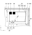
- FIG. 1 shows a plan view of an antenna device according to a first embodiment of the present invention.
- the window glass 102 for an automobile is a vehicle interior view in a state of being attached to a vehicle body.
- the window glass 102 for automobiles is installed on a metal flange 103 that forms a window opening of a vehicle body.
- the automobile window glass 102 is black from the viewpoint of preventing adhesive deterioration and aesthetics in order to conceal the adhesion portion with the metal flange 103 of the vehicle body from the outer edge 102a of the automobile window glass to an area of a predetermined width.
- a shielding film 104 is provided.
- FIG. 1 shows an example in which the black shielding film 104 is provided, it may not be provided if not necessary.
- the antenna device includes an antenna conductor 101 provided on the window glass 102 for an automobile, and a feeding point having a first feeding unit and a second feeding unit that are provided on the antenna conductor and are disposed close to each other. And an auxiliary conductor.
- the auxiliary conductor includes a horizontal conductor that is linearly provided in the horizontal direction and a vertical conductor that is electrically coupled to the horizontal conductor and provided linearly in the vertical direction.
- the horizontal conductor and the vertical conductor form a T shape, an L shape, or a cross shape.
- the antenna conductor 101 is provided in the vicinity of the coupling portion between the horizontal conductor and the vertical conductor.
- the feeding point is located at a portion along the horizontal conductor of the antenna conductor.
- the vicinity of the coupling portion is the vicinity of the coupling portion, which is a portion where the horizontal conductor and the vertical conductor overlap in plan view.
- the center frequency is 760 MHz. Therefore, when it is desired to improve the antenna gain of inter-vehicle communication, the distance a from the horizontal conductor is within 70 mm when the radio wave speed is 3.0 ⁇ 10 8 m / s and the wavelength shortening rate k is 0.64. Is desirable.
- distance b from the vertical conductor The distance between the closest part and vertical conductors in the vertical conductor in the antenna conductor 101 b (hereinafter, referred to as "distance b from the vertical conductor"), it is the vertical polarization or less 0.19Ramuda g This is desirable from the viewpoint of improving reception sensitivity.
- the distance b from the vertical conductor is preferably within 50 mm.
- FIG. 1A, FIG. 1B, FIG. 1C, and FIG. 1D examples of the positional relationship between the antenna conductor 101, the horizontal conductor, and the vertical conductor are shown. Note that this arrangement position can be similarly applied to the arrangement positions of antennas 301a, 301b, 301c, and 401 described later.
- the horizontal conductor referred to in the present embodiment allows horizontal displacement to the extent that the effects of the present embodiment are not impaired, and particularly the shape of the roof side flange of the window opening of the vehicle body where the window glass is installed. It may have a curvature along.
- the vertical conductor referred to in the present embodiment allows vertical deviation to the extent that the effects of the present embodiment are not impaired, and in particular, the shape of the pillar side flange of the window opening of the vehicle body where the window glass is installed. It may be provided in an oblique direction along.
- the antenna conductor 101 is disposed in the vicinity of a coupling portion 109a where a roof side flange 106 constituting the upper side of the vehicle metal flange 103 and a pillar side flange 105 constituting the side side are coupled at a predetermined angle.
- a roof side flange 106 constituting the upper side of the vehicle metal flange 103 and a pillar side flange 105 constituting the side side are coupled at a predetermined angle.
- the side of the metal flange 103 in the figure is referred to as a pillar 105 and the upper side is referred to as a roof 106.
- the roof 106 corresponds to a horizontal conductor and the pillar 105 corresponds to a vertical conductor.
- the distance b from the vertical conductor of the antenna conductor 101 is a distance from the upper right end portion of the antenna conductor 101 to the pillar.
- the antenna conductor 101 of FIG. 1A is mirrored in the X direction (axisymmetric with respect to the Y direction) pattern (hereinafter referred to as “antenna conductor 101b”). It is arranged in the vicinity of the joint 109b with the conductor 108v provided on the vertical center line 107 passing through the center of gravity of the automobile window glass 102.
- the roof 106 corresponds to a horizontal conductor
- the conductor 108v corresponds to a vertical conductor.
- the conductor 108v When the conductor 108v is a laminated glass in which the first glass plate and the second glass plate are bonded via an intermediate film, the conductor 108v may be configured to be provided in the intermediate film of the laminated glass.
- the structure provided in any surface may be sufficient.
- the structure provided in the intermediate film may be a structure in which the conductor 108v is provided in the interlayer film itself of the laminated glass, or a structure in which the conductor 108v, which is a separate body from the intermediate film, is sandwiched between two glass plates.
- the surface of the glass plate may be either the inner or outer surface of each of the two glass plates of laminated glass.
- the conductor 108v is particularly preferably a transparent conductive film.
- the roof 106 and the conductor 108v are electrically coupled.
- the electrical coupling may be either AC coupling or DC coupling, but it is particularly preferable that the coupling is DC coupling.
- AC coupling refers to a state in which, for example, in the coupling portion 109b, the roof 106 and the conductor 108v are capacitively coupled via an insulator in the thickness direction of the automotive window glass 102 or on the same plane.
- the roof 106 and the conductor 108v may overlap at the coupling portion 109b as shown in FIG. 1B, and when capacitively coupling on the same plane, the roof 106 and the conductor 108v are coupled.
- the part 109b may be separated.
- the length of the conductor 108v in the Y direction is preferably longer than the wavelength of the radio wave used for transmission and reception, and may not be provided over the entire length from the upper end to the lower end of the automotive window glass 102.
- the length of the conductor 108v in the X direction is not particularly limited as long as the current capacity capable of obtaining vertical polarization is obtained, but is preferably shorter than the wavelength of the radio wave used for transmission and reception.
- FIG. 1C is an example in which the conductor 108h is arranged in the horizontal direction in addition to the configuration of FIG. 1B.
- the antenna conductor 101b is disposed in the vicinity of the coupling portion 109c between the conductor 108h and the conductor 108v.
- the conductor 108h corresponds to a horizontal conductor
- the conductor 108v corresponds to a vertical conductor.
- the conductor 108h and the conductor 108v are laminated glass in which the first glass plate and the second glass plate are bonded via an intermediate film
- the conductor 108h and the conductor 108v may be provided on the interlayer film of the laminated glass.
- the structure provided on any surface of the glass plate of 1 sheet may be sufficient.
- the conductor 108h and the conductor 108v are particularly preferably transparent conductive films. Further, the conductor 108h and the conductor 108v do not have to have the same configuration, and either one may be provided on the intermediate film, and either one may be provided on the glass surface.
- the conductor 108h and the conductor 108v are electrically coupled.
- the electrical coupling may be either AC coupling or DC coupling, but it is particularly preferable that the coupling is DC coupling.
- the AC coupling refers to a state in which, for example, in the coupling portion 109c, the conductor 108h and the conductor 108v are capacitively coupled via an insulator in the thickness direction of the automotive window glass 102 or on the same plane.
- capacitive coupling is performed in the thickness direction, the conductor 108h and the conductor 108v may overlap at the coupling portion 109c.
- capacitive coupling is performed on the same plane, the conductor 108h and the conductor 108v are separated from each other at the coupling portion 109b. You may do it.
- the conductor 108v and the conductor 108h are combined to form a T shape, but the present invention is not limited to this configuration.
- the connection between the conductor 108v and the conductor 108h may have an L-shape or a cross shape.
- the conductor 108h is electrically coupled to the roof 106 in terms of improving the antenna gain. Since the electrical conductor 108h and the roof 106 are in a positional relationship, the antenna conductor 101 can be fed with the roof.
- FIG. 1D is an example in which the conductor 110 is arranged on the glass surface inside the pillar 105.
- the antenna conductor 101 is disposed in the vicinity of the joint 109 d between the roof 106 and the pillar 105.
- the roof 106 corresponds to a horizontal conductor, and since the pillar 105 and the conductor 110 are electrically coupled, the two can be regarded as a single vertical conductor.
- the conductor 110 is a laminated glass in which the first glass plate and the second glass plate are bonded via an intermediate film, the conductor 110 may have a configuration provided in the intermediate film of the laminated glass. The structure provided on the surface may be sufficient.
- the conductor 110 may be a transparent conductive film, or may be a heater wire or bus bar for removing snow or anti-fogging formed of a fired body of metal foil such as copper foil or conductive paste.
- the conductor 110 when the roof 106 and the pillar 105 are electrically coupled and the conductor 110 is sufficiently capacitively coupled to the pillar 105, the conductor 110 is indirectly coupled to the roof 106. Are electrically coupled to each other. Therefore, even if the conductor 110 is not directly electrically coupled to the roof 106, the conductor 110 can be regarded as a part of the vertical conductor.
- the length of the conductor 110 in the Y direction is preferably longer than the wavelength of the radio wave used for transmission / reception.
- the length of the conductor 110 in the X direction is not particularly limited as long as vertical polarization can be obtained, but is preferably shorter than the wavelength of the radio wave used for transmission and reception.
- the antenna conductor 101 is provided on the upper right side in the plane of the automobile window glass 102, but is not limited to this embodiment.
- the antenna conductor 101b may be provided at a position with a vertical center line 107 passing through the center of gravity of the automobile window glass 102 as an object axis.
- the antenna conductor is provided in the vicinity of the coupling portion between the horizontal conductor linearly provided in the horizontal direction and the vertical conductor electrically coupled to the horizontal conductor and provided in the vertical direction.
- the vertical polarization can be efficiently transmitted and received from both the current generated in the vertical conductor due to the arrival of the polarization and the current transmitted from the vertical conductor to the horizontal conductor.
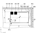
- FIG. 2 shows a case where the antenna conductor 101 in FIG. 1A is disposed in the vicinity of the coupling portion 109a where the roof 106 (horizontal conductor) as an auxiliary conductor and the pillar 105 (vertical conductor) constituting the side are coupled at a predetermined angle.
- the top view which expanded the antenna apparatus is shown.
- illustration of the black shielding film 104 is omitted in order to avoid complicated drawing.
- the pillar 105 and the roof 106 cross each other vertically.
- the antenna conductor 101 includes a feeding point of the antenna conductor (hereinafter referred to as a feeding point), a first element 201, and a second element 202.
- the feeding point is the first feeding point.
- the first element 201 has one end connected to the first power supply unit 203, and a partial element 201a extending downward in FIG. 2 and a partial element 201b extending rightward from the terminal portion of the partial element 201a. Prepare.
- the partial element 201 b extends to the end A of the extension of the first element 201. When the end A is provided in the middle of the partial element 201a, the partial element 201b may not be formed.
- the length of the first element 201 is such that the wavelength in the air at the center frequency of a predetermined frequency band is ⁇ 0 , the wavelength reduction rate of the automotive window glass 102 is k, and the automotive window glass.
- the range is from 0.2 ⁇ g to 0.35 ⁇ g .
- the center frequency is 760 MHz. Therefore, when it is desired to improve the antenna gain of inter-vehicle communication, assuming that the speed of radio waves is 3.0 ⁇ 10 8 m / s and the wavelength shortening rate k is 0.64, the length of the first element 201 is It is desirable to be 50 mm or more and 89 mm or less.
- the second element 202 has one end connected to the second power feeding unit 204 and extending in the right direction in FIG. 2, a partial element 202 b extending downward from the end of the partial element 202 a, and And a partial element 202c extending leftward from the end of the partial element 202b.
- the partial element 202 c extends to the end B of the extension of the second element 202.
- the feeding point is located at a portion along the roof 106 of the antenna conductor 101, that is, at an element along the roof 106 on the side closer to the roof 106 of the antenna conductor 101. In FIG. It is provided on the extended line along. Further, the second power supply unit 204 is disposed closer to the pillar 105 than the first power supply unit 203.
- the first element 201 and the second element 202 are arranged such that the terminal A that is the other end of the first element 201 and the terminal B that is the other end of the second element 202 are arranged close to each other.
- a notch 205 is formed between the end A and the end B. Therefore, the overall shape of the antenna conductor 101 is a half-loop shape having a notch 205 in a part of the loop shape.
- the first element 201 and the second element 202 are referred to as one element, they are expressed as “half-loop elements”.
- the partial element 201a forms the left side of the half loop element, and the partial element 201b forms a part of the lower side of the half loop element.
- the partial element 202a forms the upper side of the half-loop element and extends along the roof 106
- the partial element 202b forms the right side of the half-loop element and extends along the pillar 105
- the partial element 202c A part of the lower side of the half-loop element is formed.
- the end A of the first element 201 and the end B of the second element 202 exist on the same Y coordinate.
- the present embodiment is not limited to this embodiment. That is, the terminal A and the terminal B may exist at different Y coordinates, and the antenna conductor 101 may form a half-loop element having a step as an overall shape.
- the partial element 201b and the partial element 202c may be separated from each other in the Y direction and may overlap (hereinafter, the overlapping of the elements is expressed as “overlap”).
- the joint portion between the partial element 202a and the partial element 202b may be an arc shape according to the shape.
- the antenna conductor 101 has a rectangular half-loop element whose overall shape is rectangular, but the present invention is not limited to this form. That is, the half loop element may be a parallelogram, trapezoid, square, circle, polygon, or fan.
- the partial element 201 a and the partial element 202 b may be formed in parallel or substantially parallel to the pillar 105, and the partial element 201 b and the partial element 202 c may be formed in parallel or substantially parallel to the roof 106.
- the notch 205 separates the end A of the first element 201 and the end B of the second element 202 so that the first element 201 and the second element 202 are not electrically coupled effectively.
- Configured. “Not substantially electrically coupled” means not only being coupled in a direct current but also not being coupled in an alternating current at the operating frequency of the antenna conductor 101. For example, as shown in FIG. 8 described later, even if the half loop element is formed so that the partial element 201b and the partial element 202c overlap with each other in the notch portion 205 in the Y direction, When the length g is not long enough for the first element 201 and the second element 202 to conduct at high frequency, the length g is not substantially electrically coupled.
- the length of the overlap portion is preferably 0.06 ⁇ g or less, more preferably 0.04 ⁇ g or less.
- the length of the overlap portion is desirably less than 15 mm, and more desirably less than 10 mm.
- the notch 205 is provided on the side opposite to the roof 106 with respect to the horizontal line passing through the center point e of the region surrounded by the half loop element and on the side opposite to the pillar 105 with respect to the vertical line passing through the center point. Further, the cutout portion 205 is an angle formed by a straight line connecting the center point e and the intermediate point f of the cutout portion 205 and a horizontal line parallel to the X axis (hereinafter referred to as “an angle at which the cutout portion 205 is provided”). Is preferably located so as to be within a range of 20 ° to 75 °, and more preferably within a range of 30 ° to 65 °.
- the angle at which the notch 205 is provided is more preferably in the range of 35 ° to 60 °.
- the center point e of the region surrounded by the half-loop element refers to the center of gravity of the loop shape when it is assumed that the notch 205 of the half-loop element is not present.
- the intermediate point f of the notch 205 indicates the midpoint of a straight line connecting the end A of the first element 201 and the end B of the second element 202.
- the notch 205 is provided on the lower side of the half-loop element, but is not limited thereto. That is, depending on the angle at which the notch 205 is provided and the aspect ratio of the half-loop element (the value obtained by dividing the height of the half-loop element by the width), the notch 205 is located at a position including the lower left vertex of the half-loop element. Alternatively, it may be provided on the left side of the half loop element. This will be described in detail together with a third embodiment to be described later.
- the length of the notch 205 is not particularly limited as long as the first element 201 and the second element 202 are not directly coupled, but is preferably 0.1 mm to 5 mm.
- the length of the cutout portion 205 refers to the interval between the portions where the first element 201 and the second element 202 are closest to each other in the cutout portion. In FIG. This corresponds to the length of a straight line connecting the end A and the end B of the second element 202.
- the first power supply unit 203 and the second power supply unit 204 are parts for electrically connecting the antenna conductor 101 to a signal processing circuit (not shown) such as an amplifier via a predetermined conductive member.
- a signal processing circuit such as an amplifier
- the conductive member for example, a feeder line such as a coaxial cable is used.
- the inner conductor of the coaxial cable may be electrically connected to one of the first power feeding unit 203 and the second power feeding unit 204, and the outer conductor of the coaxial cable may be connected to the other.
- a projecting conductive member is installed at the feeding point, and the projecting conductive member contacts and / or fits to a connection portion provided on a metal flange 103 of a vehicle body to which the window glass 102 for an automobile is attached. It is good also as a structure which does.
- the feeding point may be provided partially or entirely in the peripheral region made of the black shielding film 104.
- the first power supply unit 203 and the second power supply unit 204 are arranged close to each other.
- the first power feeding unit 203 is provided in the vicinity of the upper left corner of the antenna conductor 101 in FIG.
- the position of the first power feeding unit 203 is inevitably determined by both. This will be described in detail together with a second embodiment described later.
- the aspect ratio (c / d) obtained by dividing the height c of the half-loop element by the width d is If it is 0.3 or more, a sufficient reception rate can be obtained.
- the aspect ratio is smaller than 0.3, the lower side of the half-loop element is close to the first power feeding unit 203 and / or the second power feeding unit 204, and thus may be capacitively coupled and affected by the power feeding point. Is not preferable.
- perimeter of the half-loop element is regarded as the original loop shape that does not have the gap and the notch 205 between the first feeding unit 203 and the second feeding unit 204 at the feeding point.
- a length of 1.05 ⁇ g to 1.5 ⁇ g is desirable from the viewpoint of improving transmission / reception performance.
- the expression “peripheral length of the half-loop element” is regarded as a loop shape having no gap and notch 205 between the first power supply unit 203 and the second power supply unit 204 at the power supply point. Represents the length of the outer circumference in the case of
- the gain with respect to the vehicle front direction of vertically polarized waves is high, roof power feeding is possible, and the design flexibility of the power feeding position is increased.
- the antenna conductor, the feeding point, and the conductor are formed by printing and baking a paste containing a conductive metal such as a silver paste on the inside surface of the window glass 102 for an automobile, for example.
- a linear or foil-like body made of a conductive material such as copper may be formed on the outer surface of the automobile window glass 102. It may be affixed with an adhesive or the like, or may be provided inside the automobile window glass 102 itself.
- a conductor layer made of an antenna conductor may be provided inside or on the surface of the synthetic resin film, and a synthetic resin film with a conductor layer may be formed on the vehicle inner surface or vehicle outer surface of the automotive window glass 102 to serve as an antenna conductor. good.
- a flexible circuit board on which an antenna conductor is formed may be installed on the vehicle inner surface of the automobile window glass 102 to serve as the antenna conductor.
- the shape of the feeding point should be determined according to the shape of the mounting surface of the conductive member or connector.
- a square shape or a polygonal shape such as a square, a substantially square, a rectangle, or a substantially rectangle is preferable for mounting.
- the shape of the feeding point may be a circle such as a circle, a substantially circle, an ellipse, or a substantially ellipse.
- the window glass 102 for an automobile includes not only a glass plate but also a light transmissive member made of a transparent resin plate or a composite of a glass plate and a transparent resin plate.
- the antenna conductor 101 is provided only in one place on the automobile window glass 102.
- the antenna conductor 101 is provided in a plurality of places on the same window glass or in each of a plurality of window glasses.
- Diversity reception may be performed using a plurality of antenna conductors 101. Receiving sensitivity can be further improved by performing diversity reception.
- the antenna conductor 301a of the antenna device of the second embodiment is a modification of the antenna conductor 101 of the first embodiment as shown in FIG. 3A.
- the second embodiment differs from the first embodiment in the first element 302 and is otherwise the same. For this reason, the same reference numerals are given to the same components, and descriptions thereof are omitted.
- the distance from the horizontal conductor is referred to as the distance from the roof
- the distance from the vertical conductor is referred to as the distance from the pillar in order to explain the arrangement position in FIG. 1A.
- the distance of the antenna conductor 101 from the roof 106, the distance from the pillar 105, the angle at which the notch 205 is provided, the aspect ratio of the half-loop element, and the overall length of the half-loop element are not changed.
- the partial element 201 a is not directly connected to the first power supply unit 203 but is connected to the first power supply unit 203 via the first auxiliary element 303.
- the first attachment element 303, the partial element 201a, and the partial element 201b are combined to form the first element 302, and the length of the first element 302 is the total length obtained by adding the respective lengths.
- the position of the first power feeding unit 203 is the upper left corner in FIG. 3A. It is not necessary.
- the position of the first power feeding portion 203 is The upper left corner joined to the left side and the upper side.
- FIGS. 3B and 3C examples of forming other attached elements are shown in FIGS. 3B and 3C below.
- a loop forming element 304 that has only the partial element 201a as the first element 201 and forms a loop with the first power supply unit 203 and the partial element 201a is provided.
- looping is not limited to forming a closed loop, but also includes forming an incomplete loop shape such as a U-shape in which any one side is not closed. .
- FIG. 3B shows an example in which the loop forming element 304 is formed outside the partial element 201a and the loop is formed outside one side of the antenna conductor 301b
- the present invention is not limited to this. That is, a loop may be formed inside one side of the antenna conductor 301b.
- the partial element 202C is extended beyond the position of the X coordinate of the end A of the first element 201.
- the second element 202C extends to the same position of the X coordinate as the end A of the first element 201.
- An end B of the element 202 may be provided.
- an overlap forming element 305 is provided which is connected to the second power supply unit 204 and extends along the partial element 202a.
- the partial element 202a is not directly joined to the second power supply unit 204,
- the lap forming element 305 and the overlap portion are capacitively coupled.
- power is supplied to the antenna conductor 301c by having an overlap part at any part other than the notch part 205 in any one side of the half-loop element and making the elements close to each other so as to be capacitively coupled. Since the impedance matching with the cable is improved, higher reception sensitivity can be obtained.
- the overlap forming element 305 has one end connected to the second power feeding unit 204 (or the first power feeding unit 203), and a part of the overlap forming element 305 extends and overlaps along any side of the half-loop element. Thus, an overlap portion is formed.
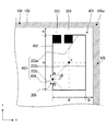
- the antenna conductor 401 of the antenna device of the third embodiment is a modification of the antenna conductor 101 of the first embodiment as shown in FIG.
- the third embodiment is different from the first embodiment in the first element 402 and the second element 403, and is otherwise the same. For this reason, the same reference numerals are given to the same components, and descriptions thereof are omitted.
- the distance from the roof 106 of the antenna conductor 101, the distance from the pillar 105, the angle at which the notch 205 is provided, the total length of the half-loop element, the position of the feeding point, the length of the first element 401 An example in which the aspect ratio of the half-loop element is changed without changing the length is shown.
- the first element 402 does not have the partial element 201a and the partial element 201b as in the first embodiment.
- the partial element 201b may not be formed depending on the aspect ratio of the half-loop element and the angle at which the notch 205 is provided.
- the second element 403 has a partial element 404 extending upward from the terminal portion of the partial element 202c.
- a partial element 404 may be provided depending on the angle at which the notch 205 is provided.
- the end A of the first element 402 and the end B of the second element 403 exist on the same X coordinate.
- the present invention is not limited to this embodiment. That is, a half loop element in which the terminal A and the terminal B exist at different X coordinates and have a step as the whole antenna conductor may be formed.
- the vertically polarized radio wave emitted from the other party in the inter-vehicle communication reaches the pillar 105 of the vehicle body.
- the pillar 105 of the vehicle body has a predetermined inclination with respect to the horizon, and the pillar 105 is narrower and longer in length than the wavelength of the transmission radio wave, so that antiphase currents are generated at intervals of about half a wavelength.
- both the current generated in the pillar 105 and the current propagated to the roof 106 can be efficiently received.
- high receiving sensitivity can be obtained.
- FIGS. 5 and 6 the antenna patterns shown in FIGS. 5 and 6 are exactly the same as those in the first embodiment, and thus the reference numerals for the respective parts are omitted here. Further, from the reversibility of the principle of transmission and reception via an antenna, here, explanation will be given using the flow of current when information is transmitted from the antenna.
- the balance is not maintained by providing the notch portion 205.
- a current flows so as to rotate on the antenna conductor from the arrow 603 to the arrow 604, the arrow 605, the arrow 606, and the arrow 607 starting from the notch 205.
- the current flows also to the point 501 and the current is not in a standing wave state, so that the radiation direction of the electric field is not fixed. That is, since the electric field is radiated in a wider range such as the direction of the arrow 609 as well as the arrows 507 and 508, it is possible to make it difficult for the receiving party to obtain an angle at which it is difficult to obtain gain.
- the antenna gain was measured by assembling a car windshield with an antenna on a car window frame on a turntable in a state of being tilted about 23 ° with respect to a horizontal plane.
- a connector is attached to the feeding point and is connected to a network analyzer via a feeder line.
- the turntable rotates so that radio waves are applied from all directions to the automobile windshield from the horizontal direction.
- the measurement of the antenna directivity is performed by setting the vehicle center of the vehicle in which the vehicle windshield with the antenna conductor 101 is assembled at the center of the turntable, and rotating the vehicle 360 °.
- the antenna directivity data is shown as values obtained by rotating the antenna gain of vertically polarized waves by 360 ° for each rotation angle of 1 ° at each frequency.
- the antenna gain was calculated as dBi by standardizing the measured value of the relative gain with respect to the half-wave dipole antenna so as to be 0 dB with an omnidirectional antenna.
- the antenna was provided at the position shown in FIG. 1A, so that the distance from the horizontal conductor is expressed as the distance from the roof 106, and the distance from the vertical conductor is expressed as the distance from the pillar 105.
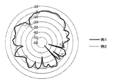
- FIG. 7 shows the result of measuring and comparing the directivity with an automotive windshield with a loop antenna that is not provided (denoted as Example 2 in FIG. 7).
- the angle at which the cutout portion 205 is provided is 40 degrees, and the aspect ratio of the half-loop element is 0.875.
- Example 2 the case where the notch part 205 was not provided was measured. Note that the size and distance of the first power supply unit 203 and the second power supply unit 204 and the length of the cutout unit 205 are the same in all the embodiments below.
- Example 2 indicated by the thick solid line compared to Example 1 indicated by the dotted line.
- the radiation direction of the electric field is not fixed, and it is difficult to generate an angle at which it is difficult to obtain a gain.
- the angle at which the cutout portion 205 is provided is 40 degrees, and the aspect ratio of the half-loop element is 0.875.
- Example 3 indicated by a thin solid line
- Example 4 indicated by a broken line
- Example 5 indicated by a dotted line
- the gain of vertically polarized waves in the 45-degree direction decreased compared to Example 1 indicated by the thick solid line.
- the overlap portion 803 cancels out with a reverse-phase current, so that the gain decreases.
- the length g of the overlap part 803 is long as in Example 3, for example, the capacity of the notch part 205 is increased and capacitively coupled, so that the behavior approaches that of a loop element not having the notch part 205.
- the overlap portion 803 is not formed. However, when the overlap portion 803 is less than 10 mm, it can be considered that the antenna conductor 101 is not substantially electrically coupled at the operating frequency of the antenna conductor 101, so that an overlap of less than 10 mm is allowed.
- the present invention is applied to communication for informing a partner of each other's position at an intersection with poor visibility using the antenna for inter-vehicle communication.
- FIG. 10 is an analysis model diagram near the intersection set in the ray tracing simulation.
- the analysis model is configured to include two connecting roads 1002 and 1003 that intersect at right angles at an intersection 1001 and four structures 1004, 1005, 1006, and 1007 other than the connecting roads 1002 and 1003.
- the maximum number of radio wave reflections was set to 10, and the radio wave diffraction frequency was set to 1.
- the radio wave reflection surfaces were only the walls of the structures 1004, 1005, 1006, and 1007 and the ground.
- the heights of the structures 1004, 1005, 1006, and 1007 are infinite, and there is no diffraction by the roof.
- a radio wave transmission point 1008 is set on the connection road 1002 side that intersects the intersection 1001
- a reception point 1009 is set on the connection road 1003 side that intersects the intersection 1001.
- the approach distance dt of the transmission point 1008 from the current location of the transmission point 1008 to the entrance on the connection road 1002 side of the intersection 1001 (the connection portion between the intersection 1001 and the connection road 1002) is the entrance (on the connection road 1003 side of the intersection 1001)
- the distance dr from the intersection 1001 and the connecting road 1003) to the receiving point 1009 is defined as a distance dr.
- dt ⁇ dr the vicinity of the intersection 1001 is transmitted, and the distance from the intersection is reception.
- the transmission point 1008 set on the connecting road 1002 is the location of the own vehicle equipped with an antenna for transmitting radio waves.
- a reception point 1009 set on the connection road 1003 assumes a location of a communication partner (for example, another vehicle) that receives a radio wave transmitted from the transmission point 1008 (own antenna).
- the propagation loss between the transmission point 1008 and the reception point 1009 is obtained by complex synthesis of the transfer function of the generated path.
- the frequency of the radio wave transmitted and received between the transmission point 1008 and the reception point 1009 is 720 MHz
- the antenna height of the transmission point 1008 and the reception point 1009 is 1.3 m
- the structure 1004 The materials of 1005, 1006, and 1007 were set to concrete (relative permittivity 6.77, conductivity 0.023), the ground plane relative permittivity was set to 3.0, and the ground plane conductivity was set to 0.0001.
- “reception rate P” is introduced as an index for uniquely evaluating the propagation characteristics changing according to the width wt of the connection road 1008, the width wr of the connection road 1009, and the distances dt and dr from the intersection 1001. To do.
- the reception points 1008 were set at intervals of 50 cm from the road width center position of the connection road 1002 to a position 1.5 m away from the structure 1006 side.
- the reception points 1009 are set at an interval of 10 cm from the center position of the road width of the connection road 1003 to the structure 1007.
- the distance dr is determined after the signal from the own vehicle is received while the other vehicle is traveling at a speed obtained by adding 10 km / h to the legal speed with respect to the intersection 1001. You may set more than the distance required in order to stop by applying a brake.
- the legal speed of the connecting road 1003 is set to 60 km / h
- the traveling speed of the other vehicle is set to 70 km / h
- the distance necessary for the other vehicle to brake and stop is assumed to be about 80 m.
- the distance dr was fixed at a constant 90 m by adding a margin of 10 m.
- the reception rate P was simulated by changing the width wt, wr and the approach distance dt. Specifically, the width wt is changed from 5 to 4 m in 5 m intervals at 2 m intervals, the width wr is changed from 4 m to 30 m in 14 ways at 2 m intervals, and the approach distance dt is changed from 9 m to 11 m in 3 m intervals at 1 m intervals. It was.
- the reception rate P is an average value of the reception rates calculated for each approach distance dt.
- Case 1 is the antenna device of this embodiment for both the transmission point 1008 and the reception point 1009.
- Case 2 is the case where the transmission point 1008 is the antenna device of this embodiment, and the reception point 1009 has characteristics equivalent to a rooftop antenna.
- Case 3 is a case where the transmission point 1008 has characteristics equivalent to a rooftop antenna, and the reception point 1009 is the glass antenna of this embodiment.
- case 1 not only vertical polarization but also horizontal polarization is added to the reception rate.
- the characteristic equivalent to the rooftop antenna is assumed to be a case where the vertical polarization gain is 0 dBi and omnidirectional, the horizontal polarization gain is ⁇ dBi, and communication is not possible with horizontal polarization.
- the antenna apparatus was provided at the arrangement position in FIG. 1A and was simulated, the distance from the horizontal conductor is expressed as the distance from the roof 106, and the distance from the vertical conductor is expressed as the distance from the pillar 105.
- each element of the antenna conductor 101 when calculating FIG. 11, the dimensions of each part, and the installation position are expressed in units of mm.
- Distance b from pillar 105 10
- Distance from roof 106 a 15
- Half loop element circumference 300 Met.
- the position of the first power feeding unit 203 was fixed to the upper left corner of the half loop element. Further, as the aspect ratio of the half-loop element, the value of c / d was changed into three types of 90 mm / 60 mm, 70 mm / 80 mm, and 50 mm / 100 mm. Further, as the length of the first element 201, the length value was changed to three types of 33 mm, 53 mm, and 73 mm.
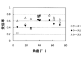
- the angle at which the notch 205 is provided was fixed at 40 degrees. Further, as the aspect ratio of the half-loop element, the value of c / d was changed to three types of 90 mm / 60 mm, 70 mm / 80 mm, and 50 mm / 100 mm (in the legend in the figure, “mm” was omitted). Further, as the length of the first element 201, the length value was changed into five types of 53 mm, 78 mm, 88 mm, 98 mm, and 108 mm.
- the length of the first element 201 is desirable in all cases 1, 2, and 3 in the range of 0.2 ⁇ g to 0.35 ⁇ g. Characteristics were obtained. Assuming ITS having a center frequency of 760 MHz, the length of the first element 201 is preferably in the range of 50 mm to 90 mm. Note that 0.2 ⁇ g is a state in which the first power feeding portion 203 is provided at the left corner of the half-loop element, and this length is set to the minimum of the first element in order to allow power feeding from the roof 106. Value.
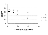
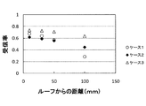
- FIG. 15 and FIG. 16 show the calculation results of the reception rates of Case 1, Case 2, and Case 3 for each case.
- the angle at which the notch 205 is provided was fixed at 40 degrees.
- FIG. 17 shows the calculation results for cases 1, 2, and 3.
- FIG. 18 shows the calculation results for cases 1, 2, and 3.
- each element of the antenna conductor 101 when calculating FIG. 18, the dimensions of each part, and the installation position are expressed in units of mm.
- the angle at which the notch 205 is provided is fixed at 40 degrees, and the aspect ratio of the half loop element is fixed at 0.875. Further, the position of the first power feeding unit was fixed to the upper left corner of the half loop element as shown in FIG.
- the length of the first element was multiplied by the rate of change of the overall length of the half-loop shape so that the angle at which the notch 205 was provided was 40 degrees.
- the total length of the half-loop element is 1.05 ⁇ g or more and 1.5 ⁇ g or less.
- the total length of the half-loop element is preferably in the range of 265 mm or more and 380 mm or less.
- FIG. 19 shows the calculation results for cases 1, 2, and 3.
- each element of the antenna conductors 101, 301b and 301c The length of each element of the antenna conductors 101, 301b and 301c, the dimensions of each part and the installation position when calculating FIG.
- Peripheral length of half loop element of antenna conductors 101, 301b and 301c 300
- Length of first element 201 53
- the angle at which the notch 205 is provided is about 40 degrees for the antenna conductors 101, 301b, and 301c.
- the horizontal axis indicates the reception rate in each case of the antenna conductors 101, 301b, and 301c.
- the antenna conductor 301b having the loop forming element 304 and looping one side of the half-loop element has a higher reception rate in all cases 1 to 3. It was confirmed that
- the antenna conductor 301c having the overlap forming element 305 and having the overlap portion other than the notch portion 205 of the half loop element as compared with the antenna conductor 101 is used in all cases 1 to 3. It was confirmed that a high reception rate was obtained.
- the present invention is an antenna device having high reception sensitivity with respect to vertical polarization, and can be suitably used for communication between vehicles, for example.
Abstract
Description
図1は本発明の第1の実施形態によるアンテナ装置の平面図を示している。図1において、自動車用窓ガラス102は、車体に取り付けられた状態の車内視である。自動車用窓ガラス102は、車体の窓開口部を形成する金属フランジ103に設置される。また、自動車用窓ガラス102は、自動車用窓ガラスの外縁102aから所定の幅の領域にかけて、車体の金属フランジ103との接着部分を隠すために、接着剤劣化防止の点及び美観の点から黒色遮蔽膜104を設けている。図1においては黒色遮蔽膜104を設けた例を示すが、不要であれば設けなくても良い。
第2の実施形態のアンテナ装置のアンテナ導体301aは、図3Aに示すように第1の実施形態のアンテナ導体101の変形である。第2の実施形態は、第1の実施形態と第1のエレメント302が異なり、その他の点では同一である。そのため同じ構成には同じ符号を付し、それらの説明は省略する。なお、下記では図1Aの配置位置の場合で説明するため、水平導体からの距離をルーフからの距離、垂直導体からの距離をピラーからの距離と表記する。
第3の実施形態のアンテナ装置のアンテナ導体401は、図4に示すように第1の実施形態のアンテナ導体101の変形である。第3の実施形態は、第1の実施形態と第1のエレメント402及び第2のエレメント403が異なり、その他の点では同一である。そのため同じ構成には同じ符号を付し、それらの説明は省略する。
次に、本願発明の一実施形態の車車間通信の送受信原理について説明する。なお、アンテナを介した送信と受信の原理の可逆性から、ここでは相手車両から発せられた電波をアンテナで受信する立場で説明する。また、以下では水平導体をルーフ106、垂直導体をピラー105として説明するが、水平導体を108h、垂直導体を108v及び110とした場合の送受信原理も同様である。
アンテナ導体を自動車用フロントガラスに設けたアンテナ付き自動車用フロントガラスを実際の自動車に取り付けて、そのアンテナ利得を実測した結果について説明する。
切り欠き部205を有する図2で示したアンテナ導体101付き自動車用フロントガラス(図7において例1と表記する)と、アンテナ導体101の終端Aと終端Bとを結合させ、切り欠き部205を有さないループアンテナ付き自動車用フロントガラス(図7において例2と表記する)との指向性を測定し、比較した結果を図7に示す。図7を実測した時のアンテナ導体101の各部の寸法(単位はmm)は、
ピラー105からの距離b:10
ルーフ106からの距離a:15
半ループエレメントの周長:300
第1のエレメントの長さ:53
第1の給電部203と第2の給電部204の縦辺:15
第1の給電部203と第2の給電部204の横辺:17.5
第1の給電部203と第2の給電部204の距離:5
切り欠き部205の長さ:2
であった。
図8のように段差を有するように構成された半ループエレメントのアンテナ導体801において、終端Aと終端Bの位置を調整してオーバーラップ部803の長さgを調整し、それぞれの場合について指向性を測定し、比較した。オーバーラップ部803の長さgが50mm、30mm、10mmの3種類について測定し、それぞれ例3、例4、例5としてその結果を図9に示す。図9を測定した時のガラスアンテナ導体101の各部の寸法(単位はmm)は、
ピラー105からの距離b:10
ルーフ106からの距離a:15
半ループエレメントの周長:300
第1のエレメント802の長さ:50
オーバーラップ部803の長さg:10、30、50
であった。
次に、本発明の一実施形態のアンテナ装置が、本実施形態のアンテナ装置同士だけでなく、ルーフトップアンテナとも良好な通信性能を確保できる点について、レイトレーシングシミュレーション(Ray Tracing Simulation)の結果を示して説明する。
図2で示したアンテナ導体101において、ピラー105からの距離、ルーフ106からの距離、第1の給電部203の位置、第2の給電部204の位置、半ループエレメントの周長を変えずに、第1のエレメントの長さと半ループエレメントのアスペクト比を変化させることで、切り欠き部205が設けられる角度が受信率に及ぼす影響について検討した。各場合の受信率の計算結果を図11に示す。
ピラー105からの距離b:10
ルーフ106からの距離a:15
半ループエレメントの周長:300
であった。
図2で示したアンテナ導体101において、ピラー105からの距離、ルーフ106からの距離、切り欠き部205が設けられる角度、半ループエレメントの周長を変えずに、第1のエレメント201の長さと半ループエレメントのアスペクト比を変化させることで、第1のエレメント201の長さが受信率に及ぼす影響について検討した。各ケース1、ケース2及びケース3の場合の受信率の計算結果を、それぞれ図12、図13、図14に示す。
ピラー105からの距離b:10
ルーフ106からの距離a:15
半ループエレメントの周長:300
であった。
図2で示したアンテナ導体101において、切り欠き部205が設けられる角度、半ループエレメントの周長、半ループエレメントのアスペクト比、第1のエレメント201の長さを変えずにピラー105からの位置及びルーフ106からの位置を変え、それぞれの場合に受信率に及ぼす影響について検討した。各場合について、ケース1、ケース2及びケース3の受信率の計算結果を、図15及び図16に示す。
半ループエレメントの周長:300
半ループエレメントのアスペクト比:70/80
第1のエレメント201の長さ:53
であった。
図2で示したアンテナ導体101において、ピラー105からの距離、ルーフ106からの距離、半ループエレメントの周長、第1のエレメント201の長さ、切り欠き部205が設けられる角度を変えずに、半ループエレメントのアスペクト比のみを変え、受信率に及ぼす影響について検討した。各ケース1、ケース2及びケース3の場合の計算結果を図17に示す。
ピラー105からの距離:10
ルーフ106からの距離:15
半ループエレメントの周長:300
第1のエレメント201の長さ:53
であった。また、切り欠き部205が設けられる角度は40度に固定した。
図2で示したアンテナ導体101において、ピラー105からの距離、ルーフ106からの距離、第1の給電部の位置、第2の給電部の位置、切り欠き部205が設けられる角度、半ループエレメントのアスペクト比を変えずに、半ループエレメントの周長を変え、受信率に及ぼす影響について検討した。各ケース1、ケース2及びケース3の場合の計算結果を図18に示す。
ピラー105からの距離:10
ルーフ106からの距離:15
であった。
図2で示したアンテナ導体101と、図3Bで示したループ形成エレメント304を設けたアンテナ導体301b、図3Cで示したオーバーラップ形成エレメント305を設けたアンテナ導体301cとを同一の条件で測定し、ループ形成エレメント304及びオーバーラップ形成エレメント305の効果について検討した。各ケース1、ケース2及びケース3の場合の計算結果を図19に示す。
アンテナ導体101、301b及び301cの半ループエレメントの周長:300
アンテナ導体101、301b及び301cの半ループエレメントのアスペクト比:70/80
第1のエレメント201の長さ:53
ループ形成エレメント304の横の長さ:15
ループ形成エレメント304の縦の長さ:53
オーバーラップ形成エレメント305の長さ:38
オーバーラップ形成エレメント305が設けられた場合の部分エレメント202aの長さ:38
オーバーラップ形成エレメント305が設けられた場合の部分エレメント202aと第2の給電部204との距離:2
であった。
101b アンテナ導体101をX方向に鏡映したパターン
102 自動車用窓ガラス
102a 自動車用窓ガラスの外縁
103 金属フランジ
104 黒色遮蔽膜
105 ピラー
106 ルーフ
107 自動車用窓ガラス102の重心を通る上下方向のセンターライン
108v、108h、110 導電体
109a、109b、109c、109d 結合部
201、302、402、802 第1のエレメント
201a、201b 部分エレメント
202、403 第2のエレメント
202a、202b、202c、404 部分エレメント
203 第1の給電部
204 第2の給電部
205 切り欠き部
303 第1の付設エレメント
304 ループ形成エレメント
305 オーバーラップ形成エレメント
501、502 点
503、504、505、506、603、604、605、606、607 電流の流れる方向
507、508、609 電界の放射方向
803 オーバーラップ部
1001 交差点
1002、1003 接続道路
1004、1005、1006、1007 構造物
1008 送信点
1009 受信点
a ガラスアンテナ101の中で水平導体に最も近い部分と水平導体との距離
b ガラスアンテナ101の中で垂直導体に最も近い部分と垂直導体との距離
c 半ループエレメントの高さ
d 半ループエレメントの幅
e 半ループエレメントで囲まれる領域の中心点
f 切り欠き部205の中心点
g オーバーラップ部の長さ
Claims (14)
- 窓ガラスに設けられたアンテナ導体と、前記アンテナ導体に設けられ互いに近接して配置される第1の給電部と第2の給電部とを有する給電点と、補助導体とを備えたアンテナ装置において、
前記補助導体は、水平方向に直線状に設けられた水平導体と、前記水平導体と電気的に結合し垂直方向に直線状に設けられた垂直導体とを有し、
前記アンテナ導体は、前記水平導体と前記垂直導体との結合部近傍に配設され、かつ一端が前記第1の給電部に接続される第1のエレメントと、一端が前記第2の給電部に接続される第2のエレメントとを有し、
前記給電点は、前記アンテナ導体の前記水平導体に沿う部位に位置し、
前記第1のエレメントと前記第2のエレメントとは、前記第1のエレメントの他端と前記第2のエレメントの他端とが近接されてループ形状の一部に切り欠き部を形成させるように半ループエレメントを構成し、
前記切り欠き部は、前記半ループエレメントで囲まれる領域の中心点を通る水平線に対して前記水平導体とは反対側かつ前記中心点を通る垂直線に対して前記垂直導体とは反対側に設けられ、
前記第1のエレメントの長さは、所定の周波数帯の中心周波数における空気中の波長をλ0とし、窓ガラスの波長短縮率をkとし、前記窓ガラス上での波長をλg=λ0・kとして、0.2λg以上0.35λg以下である
ことを特徴とするアンテナ装置。 - 前記切り欠き部は、前記中心点と前記切り欠き部の中間点を結ぶ直線と、水平線とがなす角度が20°以上75°以下の範囲に位置するように設けられた請求項1に記載のアンテナ装置。
- 前記水平導体または前記垂直導体の少なくともいずれか一方は、前記窓ガラスの表面に設けられた導体である請求項1または2に記載のアンテナ装置。
- 前記窓ガラスは、第1のガラス板と第2のガラス板とが中間膜を介して貼り合わされた合わせガラスであり、
前記水平導体または前記垂直導体の少なくともいずれか一方は、前記合わせガラスの前記中間膜に設けられた導体である請求項1から3のいずれかに記載のアンテナ装置。 - 前記水平導体は、前記窓ガラスが車体の窓開口部に設置される場合、前記車体の窓開口部のルーフ側フランジである請求項1から4のいずれかに記載のアンテナ装置。
- 前記垂直導体は、前記窓ガラスが設置される車体の窓開口部のピラー側フランジである請求項1から4のいずれかに記載のアンテナ装置。
- 前記水平導体は、前記窓ガラスが設置される車体の窓開口部のルーフ側フランジであり、前記垂直導体は、前記窓ガラスが設置される前記車体の窓開口部のピラー側フランジである請求項1または2に記載のアンテナ装置。
- 前記アンテナ導体のうち、前記水平導体に最も近接する部分は、前記水平導体から0.19λg以内の位置に設けられ、
前記アンテナ導体のうち、前記垂直導体に最も近接する部分は、前記垂直導体から0.27λg以内の位置に設けられる請求項1から7のいずれかに記載のアンテナ装置。 - 前記アンテナ導体のうち、前記水平導体に最も近接する部分は、前記水平導体から50mm以内の位置に設けられ、
前記アンテナ導体のうち、前記垂直導体に最も近接する部分は、前記垂直導体から70mm以内の位置に設けられる請求項1から7のいずれかに記載のアンテナ装置。 - 前記半ループエレメントの前記垂直方向の高さを前記半ループエレメントの前記水平方向の幅で除した値は、0.3以上となる請求項1から9のいずれかに記載のアンテナ装置。
- 前記切り欠き部の長さは0.1mm~5mmである請求項1から10のいずれかに記載のアンテナ装置。
- 前記半ループエレメントの周長は、1.05λg~1.5λgである請求項1から11のいずれかに記載のアンテナ装置。
- 前記半ループエレメントは、前記半ループエレメントのいずれかの辺をループ化するループ形成エレメントを有する請求項1から12のいずれかに記載のアンテナ装置。
- 前記半ループエレメントは、オーバーラップ形成エレメントをさらに有し、
前記オーバーラップ形成エレメントは、一端を前記第1の給電部または前記第2の給電部に接続し、一部が前記半ループエレメントのいずれかの辺に沿って延伸して重なることでオーバーラップ部を形成し、
前記オーバーラップ部は、前記切り欠き部が存在しない位置に設けられる請求項1から13のいずれかに記載のアンテナ装置。
Priority Applications (4)
| Application Number | Priority Date | Filing Date | Title |
|---|---|---|---|
| JP2015529509A JP6330811B2 (ja) | 2013-07-31 | 2014-07-16 | アンテナ装置 |
| EP14832787.7A EP3029769A4 (en) | 2013-07-31 | 2014-07-16 | Antenna device |
| CN201480042791.2A CN105409057A (zh) | 2013-07-31 | 2014-07-16 | 天线装置 |
| US14/990,853 US20160118708A1 (en) | 2013-07-31 | 2016-01-08 | Antenna device |
Applications Claiming Priority (2)
| Application Number | Priority Date | Filing Date | Title |
|---|---|---|---|
| JP2013159258 | 2013-07-31 | ||
| JP2013-159258 | 2013-07-31 |
Related Child Applications (1)
| Application Number | Title | Priority Date | Filing Date |
|---|---|---|---|
| US14/990,853 Continuation US20160118708A1 (en) | 2013-07-31 | 2016-01-08 | Antenna device |
Publications (1)
| Publication Number | Publication Date |
|---|---|
| WO2015016067A1 true WO2015016067A1 (ja) | 2015-02-05 |
Family
ID=52431607
Family Applications (1)
| Application Number | Title | Priority Date | Filing Date |
|---|---|---|---|
| PCT/JP2014/068926 WO2015016067A1 (ja) | 2013-07-31 | 2014-07-16 | アンテナ装置 |
Country Status (5)
| Country | Link |
|---|---|
| US (1) | US20160118708A1 (ja) |
| EP (1) | EP3029769A4 (ja) |
| JP (1) | JP6330811B2 (ja) |
| CN (1) | CN105409057A (ja) |
| WO (1) | WO2015016067A1 (ja) |
Cited By (1)
| Publication number | Priority date | Publication date | Assignee | Title |
|---|---|---|---|---|
| CN107615584A (zh) * | 2015-05-21 | 2018-01-19 | 旭硝子株式会社 | 车辆用窗玻璃及天线 |
Families Citing this family (5)
| Publication number | Priority date | Publication date | Assignee | Title |
|---|---|---|---|---|
| WO2018079415A1 (ja) * | 2016-10-25 | 2018-05-03 | 日本板硝子株式会社 | 窓ガラス |
| JP2018101956A (ja) * | 2016-12-21 | 2018-06-28 | トヨタ自動車株式会社 | 車両用アンテナシステム |
| WO2019073884A1 (ja) | 2017-10-10 | 2019-04-18 | Agc株式会社 | アンテナ、アンテナ付き装置及びアンテナ付き車両用窓ガラス |
| WO2019181623A1 (ja) * | 2018-03-22 | 2019-09-26 | セントラル硝子株式会社 | 車両用窓ガラス |
| KR102519079B1 (ko) * | 2018-06-19 | 2023-04-07 | 삼성전자주식회사 | 복수개의 급전 단자들을 포함하는 안테나와 통신 회로를 선택적으로 연결하는 복수의 스위치들을 포함하는 전자 장치 및 이의 구동 방법 |
Citations (4)
| Publication number | Priority date | Publication date | Assignee | Title |
|---|---|---|---|---|
| JP2009100053A (ja) | 2007-10-12 | 2009-05-07 | Toyota Central R&D Labs Inc | アンテナ |
| JP2010041256A (ja) * | 2008-08-01 | 2010-02-18 | Asahi Glass Co Ltd | 車両用ガラスアンテナ及び車両用窓ガラス |
| JP2012023707A (ja) * | 2010-06-16 | 2012-02-02 | Central Glass Co Ltd | 車両用ガラスアンテナ |
| JP2012044254A (ja) * | 2010-08-12 | 2012-03-01 | Central Glass Co Ltd | 車両用アンテナ |
Family Cites Families (4)
| Publication number | Priority date | Publication date | Assignee | Title |
|---|---|---|---|---|
| JP4738036B2 (ja) * | 2005-03-24 | 2011-08-03 | 富士通テン株式会社 | 無指向性アンテナ |
| JP4700660B2 (ja) * | 2007-08-15 | 2011-06-15 | 原田工業株式会社 | 導電線が配置されるガラスに貼付する車両用アンテナ |
| JP5269393B2 (ja) * | 2007-11-12 | 2013-08-21 | 富士通テン株式会社 | 車両用アンテナ装置 |
| BRPI1016103A2 (pt) * | 2009-04-16 | 2016-05-17 | Asahi Glass Co Ltd | antena de vidro do veículo e janela de vidro do veículo, e estrutura de alimentação para antena de vidro do veículo |
-
2014
- 2014-07-16 EP EP14832787.7A patent/EP3029769A4/en not_active Withdrawn
- 2014-07-16 CN CN201480042791.2A patent/CN105409057A/zh active Pending
- 2014-07-16 WO PCT/JP2014/068926 patent/WO2015016067A1/ja active Application Filing
- 2014-07-16 JP JP2015529509A patent/JP6330811B2/ja active Active
-
2016
- 2016-01-08 US US14/990,853 patent/US20160118708A1/en not_active Abandoned
Patent Citations (4)
| Publication number | Priority date | Publication date | Assignee | Title |
|---|---|---|---|---|
| JP2009100053A (ja) | 2007-10-12 | 2009-05-07 | Toyota Central R&D Labs Inc | アンテナ |
| JP2010041256A (ja) * | 2008-08-01 | 2010-02-18 | Asahi Glass Co Ltd | 車両用ガラスアンテナ及び車両用窓ガラス |
| JP2012023707A (ja) * | 2010-06-16 | 2012-02-02 | Central Glass Co Ltd | 車両用ガラスアンテナ |
| JP2012044254A (ja) * | 2010-08-12 | 2012-03-01 | Central Glass Co Ltd | 車両用アンテナ |
Non-Patent Citations (1)
| Title |
|---|
| See also references of EP3029769A4 * |
Cited By (3)
| Publication number | Priority date | Publication date | Assignee | Title |
|---|---|---|---|---|
| CN107615584A (zh) * | 2015-05-21 | 2018-01-19 | 旭硝子株式会社 | 车辆用窗玻璃及天线 |
| EP3300167A4 (en) * | 2015-05-21 | 2019-01-02 | AGC Inc. | Vehicle windowpane and antenna |
| US10211509B2 (en) | 2015-05-21 | 2019-02-19 | AGC Inc. | Vehicle window glass and antenna |
Also Published As
| Publication number | Publication date |
|---|---|
| EP3029769A4 (en) | 2017-03-01 |
| JPWO2015016067A1 (ja) | 2017-03-02 |
| US20160118708A1 (en) | 2016-04-28 |
| CN105409057A (zh) | 2016-03-16 |
| EP3029769A1 (en) | 2016-06-08 |
| JP6330811B2 (ja) | 2018-05-30 |
Similar Documents
| Publication | Publication Date | Title |
|---|---|---|
| JP6330811B2 (ja) | アンテナ装置 | |
| US9509038B2 (en) | Vehicle window glass and antenna | |
| US20160134013A1 (en) | Antenna device | |
| WO2017018324A1 (ja) | ガラスアンテナ及びガラスアンテナを備える車両用窓ガラス | |
| US10290932B2 (en) | Glass antenna and vehicle window glass provided with glass antenna | |
| KR101694261B1 (ko) | 안테나 장치 및 상기 안테나 장치를 이용하는 차량 | |
| JP6743486B2 (ja) | 車両用窓ガラス | |
| WO2012153663A1 (ja) | ガラスアンテナ及び窓ガラス | |
| US9837699B2 (en) | Multi-element window antenna | |
| WO2019208453A1 (ja) | 車両用アンテナ、車両用アンテナ付き窓ガラス及びアンテナシステム | |
| JP2022117929A (ja) | 車両用窓ガラス及び車両用窓ガラス装置 | |
| US11569580B2 (en) | Multilayer glass patch antenna | |
| US8542149B2 (en) | Antenna and electronic device equipped with same | |
| WO2018186375A1 (ja) | 光透過型アンテナ、窓部貼付型通信モジュール、及び、周辺監視ユニット | |
| JP6610390B2 (ja) | 車両用窓ガラス及びガラスアンテナ | |
| US11271303B2 (en) | Antenna, smart window, and method of fabricating antenna | |
| JP4693815B2 (ja) | 車載アンテナ装置 | |
| JP6729016B2 (ja) | 車両用ガラスアンテナ及び窓ガラス | |
| US11043737B2 (en) | Antenna system for vehicles | |
| WO2024036640A1 (zh) | 天线组件、信号发射装置、及车辆 | |
| WO2023002896A1 (ja) | 車両用窓ガラス及び車両用窓ガラス装置 | |
| WO2022270314A1 (ja) | 車両用無線装置 | |
| JP2021180438A (ja) | 車両用窓ガラス | |
| WO2023100908A1 (ja) | アンテナ装置及び車両用アンテナ装置 | |
| JP6402154B2 (ja) | アンテナ装置及び車載用アンテナ装置 |
Legal Events
| Date | Code | Title | Description |
|---|---|---|---|
| WWE | Wipo information: entry into national phase |
Ref document number: 201480042791.2 Country of ref document: CN |
|
| 121 | Ep: the epo has been informed by wipo that ep was designated in this application |
Ref document number: 14832787 Country of ref document: EP Kind code of ref document: A1 |
|
| ENP | Entry into the national phase |
Ref document number: 2015529509 Country of ref document: JP Kind code of ref document: A |
|
| WWE | Wipo information: entry into national phase |
Ref document number: 2014832787 Country of ref document: EP |
|
| NENP | Non-entry into the national phase |
Ref country code: DE |