WO2015015922A1 - フィルタ、および、ターゲット供給装置 - Google Patents
フィルタ、および、ターゲット供給装置 Download PDFInfo
- Publication number
- WO2015015922A1 WO2015015922A1 PCT/JP2014/065683 JP2014065683W WO2015015922A1 WO 2015015922 A1 WO2015015922 A1 WO 2015015922A1 JP 2014065683 W JP2014065683 W JP 2014065683W WO 2015015922 A1 WO2015015922 A1 WO 2015015922A1
- Authority
- WO
- WIPO (PCT)
- Prior art keywords
- flow path
- filter
- hole
- target
- region
- Prior art date
- Legal status (The legal status is an assumption and is not a legal conclusion. Google has not performed a legal analysis and makes no representation as to the accuracy of the status listed.)
- Ceased
Links
Images


















Classifications
-
- H—ELECTRICITY
- H05—ELECTRIC TECHNIQUES NOT OTHERWISE PROVIDED FOR
- H05G—X-RAY TECHNIQUE
- H05G2/00—Apparatus or processes specially adapted for producing X-rays, not involving X-ray tubes, e.g. involving generation of a plasma
- H05G2/001—Production of X-ray radiation generated from plasma
- H05G2/002—Supply of the plasma generating material
- H05G2/0023—Constructional details of the ejection system
-
- B—PERFORMING OPERATIONS; TRANSPORTING
- B01—PHYSICAL OR CHEMICAL PROCESSES OR APPARATUS IN GENERAL
- B01D—SEPARATION
- B01D29/00—Filters with filtering elements stationary during filtration, e.g. pressure or suction filters, not covered by groups B01D24/00 - B01D27/00; Filtering elements therefor
- B01D29/44—Edge filtering elements, i.e. using contiguous impervious surfaces
-
- B—PERFORMING OPERATIONS; TRANSPORTING
- B01—PHYSICAL OR CHEMICAL PROCESSES OR APPARATUS IN GENERAL
- B01D—SEPARATION
- B01D29/00—Filters with filtering elements stationary during filtration, e.g. pressure or suction filters, not covered by groups B01D24/00 - B01D27/00; Filtering elements therefor
- B01D29/44—Edge filtering elements, i.e. using contiguous impervious surfaces
- B01D29/46—Edge filtering elements, i.e. using contiguous impervious surfaces of flat, stacked bodies
-
- B—PERFORMING OPERATIONS; TRANSPORTING
- B01—PHYSICAL OR CHEMICAL PROCESSES OR APPARATUS IN GENERAL
- B01D—SEPARATION
- B01D46/00—Filters or filtering processes specially modified for separating dispersed particles from gases or vapours
- B01D46/40—Particle separators, e.g. dust precipitators, using edge filters, i.e. using contiguous impervious surfaces
- B01D46/406—Particle separators, e.g. dust precipitators, using edge filters, i.e. using contiguous impervious surfaces of stacked bodies
-
- G—PHYSICS
- G03—PHOTOGRAPHY; CINEMATOGRAPHY; ANALOGOUS TECHNIQUES USING WAVES OTHER THAN OPTICAL WAVES; ELECTROGRAPHY; HOLOGRAPHY
- G03F—PHOTOMECHANICAL PRODUCTION OF TEXTURED OR PATTERNED SURFACES, e.g. FOR PRINTING, FOR PROCESSING OF SEMICONDUCTOR DEVICES; MATERIALS THEREFOR; ORIGINALS THEREFOR; APPARATUS SPECIALLY ADAPTED THEREFOR
- G03F7/00—Photomechanical, e.g. photolithographic, production of textured or patterned surfaces, e.g. printing surfaces; Materials therefor, e.g. comprising photoresists; Apparatus specially adapted therefor
- G03F7/70—Microphotolithographic exposure; Apparatus therefor
- G03F7/70058—Mask illumination systems
- G03F7/70191—Optical correction elements, filters or phase plates for controlling intensity, wavelength, polarisation, phase or the like
Definitions
- This disclosure relates to a filter and a target supply device.
- the EUV light generation apparatus includes an LPP (Laser Produced Plasma) system using plasma generated by irradiating a target material with laser light, and a DPP (Discharge Produced Plasma) using plasma generated by discharge.
- LPP Laser Produced Plasma
- DPP discharge Produced Plasma
- Three types of devices are known: a system device and an SR (Synchrotron Radiation) device using orbital radiation.
- a filter according to an aspect of the present disclosure includes a first member having a flow path formed on a first surface, and a second member disposed so that a second surface covers the flow path.
- the two members circulate a fluid between the second surface and the second space on the opposite surface side to the second surface via a second region spaced from the first region of the flow path.
- the 2nd distribution part for this may be provided.
- a target supply device includes a nozzle in which a nozzle hole for outputting a target material is formed, a target generator that accommodates the target material therein, and is disposed in the target generator.
- a filter for suppressing foreign matter in the target material from blocking the nozzle hole wherein the filter includes a first member having a flow path formed on a first surface, and a second surface blocking the flow path.
- a second member disposed so as to cover the first member, and the first member includes a first region of the flow path between the first surface and a first space on the opposite side of the first surface.
- a second flow path between the second surface and the second space on the opposite surface side of the second surface. Through the second region spaced apart from the first region.
- Tsu DOO material may comprise a second circulation unit for circulating.
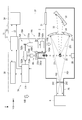
- FIG. 1 schematically shows a configuration of an LPP EUV light generation apparatus.
- FIG. 2 schematically shows a configuration of an EUV light generation apparatus including a target supply apparatus according to the first embodiment.
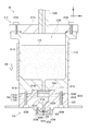
- FIG. 3 schematically shows the configuration of the target supply apparatus.
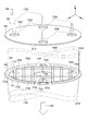
- FIG. 4 is a perspective view schematically showing the second filter.
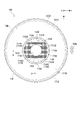
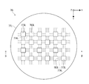
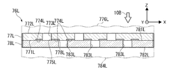
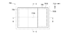
- FIG. 5A schematically shows a configuration of the second filter according to the second embodiment viewed from the + Z direction side.
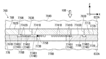
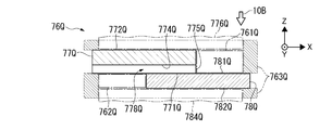
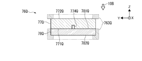
- FIG. 5B is a cross-sectional view taken along line BB in FIG. 5A.
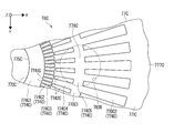
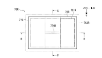
- FIG. 5C schematically shows a configuration of the flow path of the second filter when viewed from the + Z direction side.
- FIG. 5A schematically shows a configuration of the flow path of the second filter when viewed from the + Z direction side.
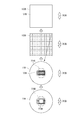
- FIG. 6 schematically shows a method for manufacturing the first member.
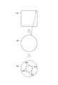
- FIG. 7 schematically shows a method for manufacturing the second member.
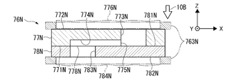
- FIG. 8A schematically shows a configuration of the second filter according to the third embodiment viewed from the + Z direction side.
- FIG. 8B is a cross-sectional view taken along line BB in FIG. 8A.
- FIG. 8C schematically shows a configuration of the flow path of the second filter when viewed from the + Z direction side.
- FIG. 9A schematically shows a configuration of the second filter according to the fifth embodiment viewed from the + Z direction side.
- FIG. 9B is a sectional view taken along line BB in FIG. 9A.
- FIG. 10A schematically illustrates a configuration of the second filter according to the fifth embodiment when viewed from the + Z direction side.
- FIG. 10A schematically illustrates a configuration of the second filter according to the fifth embodiment when viewed from the + Z direction side.
- FIG. 10B is a cross-sectional view taken along line BB in FIG. 10A.
- FIG. 11A schematically illustrates a configuration of the second filter according to the sixth embodiment when viewed from the + Z direction side.
- FIG. 11B is a cross-sectional view taken along line BB in FIG. 11A.
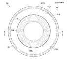
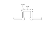
- FIG. 11C schematically shows a modification of the flow path of the second filter.
- FIG. 12 schematically shows a method for manufacturing the second filter.
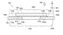
- FIG. 13A schematically shows a main part of a target supply device according to a seventh embodiment.
- FIG. 13B is a cross-sectional view taken along line BB in FIG. 13A.
- FIG. 14 schematically shows a main part of a target supply apparatus according to the eighth embodiment.
- FIG. 13A schematically shows a main part of a target supply device according to a seventh embodiment.
- FIG. 13B is a cross-sectional view taken along line BB in FIG. 13A.
- FIG. 14 schematically shows a
- FIG. 15A schematically shows a main part of the target supply device according to the ninth embodiment.
- FIG. 15B is a sectional view taken along line BB in FIG. 15A.
- FIG. 16 schematically illustrates a main part of the target supply device according to the tenth embodiment.
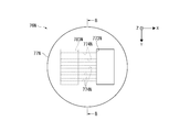
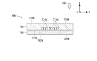
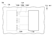
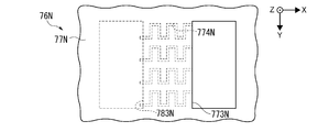
- FIG. 17A schematically shows a configuration of the filter according to the first modification viewed from the + Z direction side.
- FIG. 17B is a cross-sectional view taken along line BB in FIG. 17A.
- FIG. 18A schematically shows a configuration of the filter according to the second modification viewed from the + Z direction side.
- 18B is a cross-sectional view taken along line BB in FIG. 18A.
- FIG. 19A schematically shows a configuration of the filter according to the third modification viewed from the + Z direction side.
- FIG. 19A schematically shows a configuration of the filter according to the third modification viewed from the + Z direction side.
- FIG. 19B is a cross-sectional view taken along line BB in FIG. 19A.
- FIG. 19C is a cross-sectional view taken along the line CC of FIG. 19A.
- FIG. 20A schematically shows a configuration in which another filter according to the third modification is viewed from the + Z direction side.
- 20B is a cross-sectional view taken along line BB in FIG. 20A.
- FIG. 21A schematically shows a configuration in which another filter according to the third modification is viewed from the + Z direction side.
- FIG. 21B schematically shows a configuration of another filter according to the third modification viewed from the + Z direction side.
- FIG. 21C schematically shows a configuration of another filter according to the third modification viewed from the + Z direction side.
- FIG. 21A schematically shows a configuration in which another filter according to the third modification is viewed from the + Z direction side.
- FIG. 21B schematically shows a configuration of another filter according to the third modification viewed from the + Z direction side.
- FIG. 21D schematically shows a configuration of another filter according to the third modification viewed from the + Z direction side.
- FIG. 21E schematically shows a configuration of another filter according to the third modification viewed from the + Z direction side.
- FIG. 21F schematically illustrates a configuration in which another filter according to the third modification is viewed from the + Z direction side.
- FIG. 21G schematically shows a configuration of another filter according to the third modification viewed from the + Z direction side.
- FIG. 22A schematically shows a configuration of a filter according to a fourth modification viewed from the + Z direction side.
- 22B is a cross-sectional view taken along line BB in FIG. 22A.
- 22C is a cross-sectional view taken along the line CC of FIG. 22A.
- FIG. 23A schematically shows a configuration of a filter according to a fifth modification viewed from the + Z direction side.
- FIG. 23B is a sectional view taken along line BB in FIG. 23A.
- FIG. 23C is a cross-sectional view taken along the line CC of FIG. 23A.
- FIG. 24A schematically shows a configuration of a filter according to a sixth modification viewed from the + Z direction side.
- 24B is a cross-sectional view taken along line BB in FIG. 24A.
- 24C is a cross-sectional view taken along the line CC of FIG. 24A.
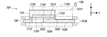
- FIG. 25 is a cross-sectional view of a filter according to a seventh modification.
- FIG. 26 is a cross-sectional view of a filter according to an eighth modification.
- a filter includes a first member having a flow path formed on a first surface, and a second member disposed so that a second surface covers the flow path, and the first member Comprises a first flow part for flowing a fluid between the first surface and the first space on the opposite side of the first surface through the first region of the flow path, and the second member is A second circulation part for circulating fluid between the second surface and the second space on the opposite side of the second surface via a second region separated from the first region of the flow path. You may prepare.
- the target supply device includes a nozzle in which a nozzle hole for outputting a target material is formed, and a target generator that accommodates the target material therein is disposed in the target generator.
- a filter for suppressing foreign matter in the target material from blocking the nozzle hole and the filter includes a first member having a flow path formed on the first surface and a second surface covering the flow path.
- the second member has a second region separated from the first region of the flow path between the second surface and the second space on the opposite surface side of the second surface.
- a second distribution part for distributing the target material may be provided.
- FIG. 1 schematically shows a configuration of an exemplary LPP type EUV light generation system.
- the EUV light generation apparatus 1 may be used together with at least one laser apparatus 3.
- a system including the EUV light generation apparatus 1 and the laser apparatus 3 is referred to as an EUV light generation system 11.
- the EUV light generation apparatus 1 may include a chamber 2 and a target supply apparatus 7.
- the chamber 2 may be sealable.
- the target supply device 7 may be attached so as to penetrate the wall of the chamber 2, for example.
- the material of the target substance supplied from the target supply device 7 may include, but is not limited to, tin, terbium, gadolinium, lithium, xenon, or a combination of any two or more thereof.
- the wall of the chamber 2 may be provided with at least one through hole.
- a window 21 may be provided in the through hole, and the pulse laser beam 32 output from the laser device 3 may pass through the window 21.
- an EUV collector mirror 23 having a spheroidal reflecting surface may be disposed.
- the EUV collector mirror 23 may have first and second focal points.
- On the surface of the EUV collector mirror 23, for example, a multilayer reflective film in which molybdenum and silicon are alternately laminated may be formed.
- the EUV collector mirror 23 is preferably arranged such that, for example, the first focal point thereof is located in the plasma generation region 25 and the second focal point thereof is located at the intermediate focal point (IF) 292.
- a through hole 24 may be provided at the center of the EUV collector mirror 23, and the pulse laser beam 33 may pass through the through hole 24.
- the EUV light generation apparatus 1 may include an EUV light generation control unit 5, a target sensor 4, and the like.
- the target sensor 4 may have an imaging function, and may be configured to detect the presence, locus, position, speed, and the like of the droplet (target) 27.
- the EUV light generation apparatus 1 may include a connection unit 29 that allows the inside of the chamber 2 and the inside of the exposure apparatus 6 to communicate with each other.
- a wall 291 in which an aperture 293 is formed may be provided inside the connection portion 29.
- the wall 291 may be arranged such that its aperture 293 is located at the second focal position of the EUV collector mirror 23.
- the EUV light generation apparatus 1 may include a laser beam traveling direction control unit 34, a laser beam focusing mirror 22, a target recovery unit 28 for recovering the droplet 27, and the like.
- the laser beam traveling direction control unit 34 may include an optical element for defining the traveling direction of the laser beam and an actuator for adjusting the position, posture, and the like of the optical element.
- the pulsed laser beam 31 output from the laser device 3 passes through the window 21 as the pulsed laser beam 32 through the laser beam traveling direction control unit 34 and enters the chamber 2. May be.
- the pulsed laser beam 32 may travel through the chamber 2 along at least one laser beam path, be reflected by the laser beam collecting mirror 22, and irradiate at least one droplet 27 as the pulsed laser beam 33.
- the target supply device 7 may be configured to output the droplet 27 toward the plasma generation region 25 inside the chamber 2.
- the droplet 27 may be irradiated with at least one pulse included in the pulsed laser light 33.
- the droplet 27 irradiated with the pulsed laser light is turned into plasma, and radiation light 251 can be emitted from the plasma.
- the EUV light 252 included in the radiation light 251 may be selectively reflected by the EUV collector mirror 23.
- the EUV light 252 reflected by the EUV collector mirror 23 may be condensed at the intermediate condensing point 292 and output to the exposure apparatus 6.
- a single droplet 27 may be irradiated with a plurality of pulses included in the pulse laser beam 33.
- the EUV light generation controller 5 may be configured to control the entire EUV light generation system 11.
- the EUV light generation controller 5 may be configured to process the image data of the droplet 27 captured by the target sensor 4.
- the EUV light generation controller 5 may be configured to control, for example, the timing at which the droplet 27 is output, the output direction of the droplet 27, and the like.
- the EUV light generation control unit 5 may be configured to control, for example, the oscillation timing of the laser device 3, the traveling direction of the pulse laser light 32, the condensing position of the pulse laser light 33, and the like.
- the various controls described above are merely examples, and other controls may be added as necessary.
- the first flow part may be configured by a first through hole that penetrates the first member.
- the first through hole may be formed so as to penetrate substantially the center of the first member.
- the second flow part may be configured by a second through hole that penetrates the second member.
- the flow path may be configured by a groove formed on the first surface.
- FIG. 2 schematically shows a configuration of an EUV light generation apparatus including a target supply apparatus according to the first embodiment.
- FIG. 3 schematically shows the configuration of the target supply apparatus.
- FIG. 4 is a perspective view schematically showing the second filter.
- the EUV light generation apparatus 1A may include a chamber 2 and a target supply apparatus 7A as shown in FIG.
- the target supply device 7A may include a target generation unit 70A and a target control device 71A.
- the laser device 3 and the EUV light generation controller 5A may be electrically connected to the target control device 71A.
- the target generation unit 70A may include a target generator 8A, a pressure control unit 73A, a temperature control unit 74A, a first filter 75A, and a second filter 76A.
- the target generator 8A may include a tank 81A, a nozzle base end portion 82A, and a nozzle front end portion 83A.
- the tank 81A, the nozzle base end portion 82A, and the nozzle tip end portion 83A may be made of a material having low reactivity with the target material 270 such as molybdenum, for example.
- the tank 81A may include a tank body 811A and a lid 812A.
- the tank body 811A may be formed in a substantially cylindrical shape having a wall surface on the second surface on the ⁇ Z direction side.
- the hollow portion of the tank main body 811A may be an accommodation space 810A.
- a concave portion 813A that is recessed in a substantially circular shape toward the + Z direction may be provided at the center of the second surface of the tank body 811A.
- a first through hole 814A that communicates with the accommodation space 810A may be provided at the center of the recess 813A.
- the lid 812A may be formed in a substantially disk shape that closes the first surface on the + Z direction side of the tank body 811A.
- the lid 812A may be fixed to the first surface of the tank body 811A by a plurality of bolts 815A.
- the nozzle base end portion 82A may be formed in a substantially cylindrical shape.
- a first convex portion 821A similar to the shape of the concave portion 813A of the tank body 811A may be provided on the first surface on the + Z direction side of the nozzle base end portion 82A.
- the nozzle base end portion 82A may be fixed to the second surface of the tank body 811A by a plurality of bolts 829A.
- a second through hole 822A penetrating in the Z-axis direction may be provided at the center of the nozzle base end portion 82A.
- the second through hole 822A may communicate with the first through hole 814A.
- the + Z direction side in the second through hole 822A may be the accommodating portion 823A.
- the housing portion 823A may house the first filter 75A and the shim 755A.
- the accommodating portion 823A may include a first contact portion 824A and a second contact portion 825A.
- a second convex portion 826A may be provided on the second surface on the ⁇ Z direction side of the nozzle base end portion 82A.
- the second convex portion 826A may protrude in a substantially disc shape in the ⁇ Z direction.
- a concave portion 827A that is recessed in a substantially circular shape in the + Z direction may be provided at the center of the second convex portion 826A.
- An opening of the second through hole 822A may exist in the recess 827A.
- the second filter 76A may be inserted into the recess 827A.
- the nozzle tip portion 83A may be formed in a substantially disc shape. In the center of the first surface of the nozzle tip 83A, a recess 831A that is recessed in a substantially circular shape in the ⁇ Z direction may be provided. The second convex portion 826A of the nozzle base end portion 82A may be fitted into the concave portion 831A. At this time, the recess 831A may contact the second filter 76A.
- the nozzle tip portion 83A may be fixed to the second surface of the nozzle base end portion 82A by a plurality of bolts 839A penetrating the nozzle tip portion 83A.
- a third through hole 832A penetrating in the Z-axis direction may be provided at the center of the nozzle tip portion 83A.
- the third through hole 832A may communicate with the second through hole 822A.
- the third through-hole 832A may have a shape that decreases in diameter as it goes in the ⁇ Z direction.
- the end of the third through hole 832A on the ⁇ Z direction side may be a nozzle hole 833A.
- the nozzle hole 833A may be a circular opening and may have a diameter of 1 ⁇ m to 3 ⁇ m.
- the nozzle tip portion 83A may be a nozzle in which a nozzle hole 833A is formed.
- the member in which the nozzle hole is formed may be simply referred to as a nozzle.
- the nozzle tip 83A is preferably made of a material having a contact angle between the nozzle tip 83A and the target material 270 of 90 ° or more.
- at least the surface of the nozzle tip 83A may be coated with a material having a contact angle of 90 ° or more.
- the material having a contact angle of 90 ° or more may be SiC, SiO 2 , Al 2 O 3 , molybdenum, or tungsten.
- the tank 81A, the nozzle base end portion 82A, and the nozzle tip end portion 83A may be made of an electrically insulating material.
- an electrically insulating material (not shown) may be disposed between the chamber 2 and the target generator 8A.
- the preset output direction of the droplet 27 may be, for example, the central axis direction of the nozzle hole 833A, or may be the ⁇ Z direction in FIG.
- the preset output direction of the droplet 27 is referred to as a set output direction 10A.
- the set output direction 10A does not necessarily coincide with the gravity direction 10B.
- the droplet 27 may be output in an oblique direction with respect to the gravity direction 10B.
- the chamber 2 may be installed so that the set output direction 10A matches the gravity direction 10B.
- the pressure control unit 73A may include a pressure controller 732A and a pressure sensor 733A.
- the pressure controller 732A may be coupled to the first end portion on the + Z direction side of the lid portion 812A via the pipe 734A.
- An inert gas cylinder 731A may be connected to the pressure controller 732A via a pipe 735A.
- the pressure controller 732A may be electrically connected to the target control device 71A.
- the pressure controller 732A is configured to adjust the pressure in the target generator 8A by controlling the pressure of the inert gas supplied from the inert gas cylinder 731A based on the signal transmitted from the target control device 71A. May be.
- the pressure sensor 733A may be provided in the pipe 734A.
- the pressure sensor 733A may be electrically connected to the target control device 71A.
- the pressure sensor 733A may detect the pressure of the inert gas present in the pipe 734A and transmit a signal corresponding to the detected pressure to the target control device
- the temperature control unit 74A may be configured to control the temperature of the target material 270 in the tank 81A.
- the temperature control unit 74A may include a heater 741A, a heater power source 742A, a temperature sensor 743A, and a temperature controller 744A.
- the heater 741A may be provided on the outer peripheral surface of the tank body 811A of the tank 81A.
- the heater power supply 742A may supply power to the heater 741A based on a signal from the temperature controller 744A to cause the heater 741A to generate heat. Thereby, the target material 270 in the tank 81A can be heated via the tank 81A.
- the temperature sensor 743A may be provided on the nozzle base end portion 82A side on the outer peripheral surface of the tank 81A, or may be provided in the tank 81A.
- the temperature sensor 743A may be configured to detect mainly the temperature of the installation position of the temperature sensor 743A and a position near the temperature sensor 743A in the tank 81A, and transmit a signal corresponding to the detected temperature to the temperature controller 744A.
- the temperature at the position where the temperature sensor 743A is installed and the vicinity thereof can be a temperature reflecting the temperature of the target material 270 in the tank 81A.
- the temperature controller 744A may be configured to output a signal for controlling the temperature of the target material 270 to a predetermined temperature to the heater power source 742A based on a signal from the temperature sensor 743A.
- the target material 270 may contain particles as foreign matter.
- the particles can be generated by the reaction of the target material 270 with impurities or oxygen, can be included in the raw material of the target material 270, or can be generated by physical wear of the target material 270 and the tank 81A.
- the first filter 75A may include a first porous filter 751A, a second porous filter 752A, and a third porous filter 753A.
- the first, second, and third porous filters 751A, 752A, and 753A may be made of a porous material in order to collect particles contained in the target material 270.
- the first porous filter 751A may be provided with countless through pores having a diameter of, for example, about 20 ⁇ m.
- the second porous filter 752A may be provided with countless through pores having a diameter of, for example, about 10 ⁇ m.
- the third porous filter 753A may be provided with innumerable through pores having a diameter of about 6 ⁇ m, for example.
- the sizes of the through holes of the first porous filter 751A, the second porous filter 752A, and the third porous filter 753A may be different. Further, the through pores of the first, second, and third porous filters 751A, 752A, and 753A may be bent in various directions and pass through the respective porous filters.
- the first, second, and third porous filters 751A, 752A, and 753A may be formed in a substantially disk shape, and the diameter thereof may be larger than the maximum inner diameter of the second through hole 822A.
- the first, second, and third porous filters 751A, 752A, and 753A are accommodated in the accommodating portion 823A so as to close the second through hole 822A and overlap in the Z-axis direction in the second through hole 822A. Also good.
- the first porous filter 751A may be located on the + Z direction side
- the third porous filter 753A may be located on the ⁇ Z direction side.
- a porous filter having small through pores may be arranged along the output direction of the target material 270.
- the first, second, and third porous filters 751A, 752A, and 753A may be formed of a material that has low reactivity with the target material 270.
- the difference between the linear thermal expansion coefficient of the material constituting the first, second and third porous filters 751A, 752A and 753A and the linear thermal expansion coefficient of the material constituting the target generator 8A constitutes the target generator 8A. It may be smaller than 20% of the linear thermal expansion coefficient of the material.
- the target generator 8A may be formed of molybdenum having low reactivity with tin.
- the first, second, and third porous filters 751A, 752A, and 753A are made of any of the materials shown in Table 1 below. May be.
- the coefficient of linear thermal expansion of molybdenum is 5.2 ⁇ 10 ⁇ 6 .
- the linear thermal expansion coefficient of tungsten is 4.6 ⁇ 10 ⁇ 6 .
- the material of the first, second, and third porous filters 751A, 752A, and 753A may be, for example, shirasu porous glass (SPG) provided by SPG Techno Co., Ltd.
- SPG may be a porous glass made from volcanic ash shirasu.
- the first, second, and third porous filters 751A, 752A, and 753A may be formed in a substantially disc shape, for example, the first, second, and third porous filters.
- the Z-axis direction dimension which is the thickness dimension of the filters 751A, 752A, and 753A, may be about 3 mm, and the diameters of the first, second, and third porous filters 751A, 752A, and 753A are about 20 mm. There may be.
- the SPG composition ratio may be the ratio shown in Table 2 below.
- the first, second, and third porous filters 751A, 752A, and 753A have an infinite number of through-holes that have a diameter of 6 ⁇ m to 20 ⁇ m and bend in various directions. Can be provided.
- a shim 755A may be overlaid on the first surface on the + Z direction side of the first porous filter 751A.
- two shims 755A may be stacked inside the accommodating portion 823A.
- their thicknesses may be the same or different.
- the shim 755A may be formed of a material having low reactivity with the target material 270.
- the difference between the linear thermal expansion coefficient of the material constituting the first, second and third porous filters 751A, 752A and 753A and the linear thermal expansion coefficient of the material constituting the shim 755A is the line of the material constituting the shim 755A. It may be smaller than 20% of the thermal expansion coefficient.
- the shim 755A may be formed of molybdenum.
- the shim 755A may be formed in a substantially annular plate shape.
- the second filter 76A may be a filter according to the present disclosure.
- the second filter 76A may be provided so as to close the third through hole 832A on the ⁇ Z direction side of the first filter 75A.
- the ⁇ Z direction side may be the output direction of the target material 270.
- the second filter 76A may collect particles that have passed through the third porous filter 753A and / or particles that are generated downstream in the output direction of the target material 270 from the third porous filter 753A.
- the second filter 76A may include a first member 77A and a second member 78A.
- the first and second members 77A and 78A may be formed in a substantially disk shape with a material having low reactivity with the target material 270.
- the material having low reactivity with the target substance 270 may be molybdenum or tungsten when the target substance 270 is tin, or may be any of the materials shown in Table 1.
- the thickness dimension of the first and second members 77A and 78A may be about 300 ⁇ m.
- a substantially circular first through hole 773A penetrating in the Z-axis direction may be provided at the center of the first member 77A.
- the diameter of the first through hole 773A may be 600 ⁇ m.
- a flow path 774A may be formed on the first surface 771A on the + Z direction side of the first member 77A.
- the flow path 774A may be configured by a plurality of grooves.
- the flow paths 774A may be formed in a lattice shape or may be formed in a radial shape. In FIG. 4, the flow path 774A may be configured by grooves formed in a lattice shape on the first surface 771A.
- the flow path 774A may be formed by etching the first surface 771A of the first member 77A.
- the dimension in the orthogonal direction of the first surface 771A which is the depth dimension of the flow path 774A, may be smaller than the dimension of the particles that have passed through the third porous filter 753A.
- the depth dimension of the flow path 774A may be 3 ⁇ m or less.
- the flow path 774A can collect particles.
- the flow path 774A may extend to the first through hole 773A.
- the end of the flow path 774A on the first through hole 773A side may be the first region 775A.
- the first through hole 773A passes between the first surface 771A and the first space 776A on the third surface 772A opposite to the first surface 771A via the first region 775A of the flow path 774A.
- circulating the target material 270 as a fluid can be comprised.
- the first through hole 773A may constitute a first flow part for causing the target material 270 flowing into the first region 775A of the flow path 774A to flow out into the first space 776A.
- a flat surface portion 777A may be provided outside the flow path 774A on the first surface 771A of the first member 77A.
- the flat surface portion 777A may be provided in an annular shape surrounding the flow path 774A.
- the flat portion 777A may be an unetched region on the first surface 771A.
- the flat portion 777A and the third surface 772A may be polished.
- the second member 78A may be arranged so as to overlap from the ⁇ Z direction side of the first member 77A as indicated by a two-dot chain line in FIG.
- the second member 78A may be arranged such that the second surface 781A covers a part of the flow path 774A of the first member 77A.
- the second member 78A may be provided with four substantially circular second through holes 783A penetrating in the Z-axis direction.
- the diameter of the second through hole 783A may be 400 ⁇ m.
- the second through holes 783A may be provided at substantially equal intervals along the outer circumferential direction of the second member 78A. Accordingly, the second through hole 783A can be provided point-symmetrically with respect to the center of the second member 78A.
- the second through-hole 783A may be provided so as not to be positioned within the opening of the first through-hole 773A when the second member 78A is placed on the first member. At this time, a part of the flow path 774A may be located in the opening of the second through hole 783A.
- the region located in the opening of the second through hole 783A in the flow path 774A may be a second region 778A that is separated from the first region. Accordingly, the second through hole 783A is interposed between the second surface 781A and the second space 784A on the fourth surface 782A side opposite to the second surface 781A via the second region 778A of the flow path 774A.
- circulating the target material 270 may be comprised.
- the second through hole 783A may constitute a second flow part for allowing the target material 270 existing in the second space 784A to flow into the second region 778A of the flow path 774A.
- the second surface 781A and the fourth surface 782A may be polished.
- the target control device 71A may control the temperature of the target material 270 in the target generator 8A by transmitting a signal to the temperature controller 744A.
- the target control device 71A may control the pressure in the target generator 8A by transmitting a signal to the pressure controller 732A of the pressure control unit 73A.
- the operation of incorporating the filter may be performed when the target generator 8A is assembled or when the target generator 8A is maintained.
- the first member 77A in which the first through hole 773A and the flow path 774A are formed may be manufactured in advance.
- the second member 78A in which the second through hole 783A is formed may be manufactured.
- the first member 77A and the second member 78A may be manufactured by the same method as in the second embodiment described later.
- the second member 78A and the first member 77A may be arranged so that the second surface 781A of the second member 78A covers the flow path 774A of the first member 77A.
- the first member 77A and the second member 78A may be diffusion bonded.
- the 2nd filter 76A which has the flow path 774A whose depth dimension is 3 micrometers or less can be formed.
- diffusion bonding between the first member and the second member may not be essential.
- the second filter 76A may be inserted into the recess 827A of the nozzle base end portion 82A. Thereafter, the second convex portion 826A of the nozzle base end portion 82A may be inserted into the concave portion 831A of the nozzle tip portion 83A, and the bolt 839A may be screwed into the nozzle base end portion 82A. Thus, the bolt 839A is screwed into the nozzle base end portion 82A, so that the second member 78A of the second filter 76A is interposed between the third surface 772A of the first member 77A of the second filter 76A and the nozzle tip portion 83A.
- the nozzle distal end portion 83A can be fixed to the nozzle proximal end portion 82A so that the space between the fourth surface 782A and the nozzle proximal end portion 82A is sealed.
- the four second through holes 783A of the second member 78A are located in the opening of the second through hole 822A, and the inside of the second through hole 822A can be the second space 784A.
- the first through hole 773A of the first member 77A is located in the opening on the + Z direction side of the third through hole 832A, and the inside of the third through hole 832A can be the first space 776A.
- first filter 75A and the shim 755A may be disposed in the accommodating portion 823A of the nozzle base end portion 82A.
- first convex portion 821A of the nozzle base end portion 82A may be fitted into the concave portion 813A of the tank body 811A.
- the bolt 829A may be screwed into the tank body 811A.
- the target control device 71A may heat the target generator 8A to a temperature equal to or higher than the melting point of the target material 270. Thereafter, the target control apparatus 71A may adjust the pressure in the target generator 8A to the first pressure. By adjusting the pressure, the liquid target material 270 can pass through the first porous filter 751A. When the target material 270 passes through the first porous filter 751A, the first porous filter 751A can collect particles larger than the diameter of the through pore.
- the target material 270 that has passed through the first porous filter 751A can pass through the second porous filter 752A.
- the second porous filter 752A can collect particles larger than the diameter of the through pore.
- the target material 270 that has passed through the second porous filter 752A can pass through the third porous filter 753A.
- the third porous filter 753A can collect particles larger than the diameter of the through pore.
- the target material 270 may pass through the second filter 76A.
- particles may exist in the target material 270 that has reached the second filter 76A.
- the first and second porous filters 751A, 752A, and 753A are formed when the first, second, and third porous filters 751A, 752A, and 753A are formed or attached to the nozzle base end portion 82A. Or could not be collected by the first, second and third porous filters 751A, 752A and 753A.
- the second filter 76A can collect the particles.
- the target material 270 that has reached the second filter 76A can flow into the second through hole 783A of the second member 78A from the direction of the arrow 710A on the ⁇ Z direction side.
- the target material 270 that has flowed into the second through hole 783A can pass through the flow path 774A.
- the flow path 774A can collect particles larger than the depth dimension of the flow path 774A.
- the target material 270 may pass through the first through hole 773A, pass through the second filter 76A in the direction of the arrow 710B on the ⁇ Z direction side, and flow into the third through hole 832A.
- the target control apparatus may adjust the pressure in the target generator 8A to the second pressure and output the target material 270 as the droplet 27 from the nozzle hole 833A.
- the second filter 76A capable of collecting fine particles can be easily obtained simply by disposing the second member 78A so that the second surface 781A covers the flow path 774A of the first member 77A. Can be manufactured. Compared with the case where the flow path 774A is formed by drilling, the flow path 774A capable of collecting fine particles can be easily formed. Compared to the case where the flow path 774A is formed by drilling, the flow path 774A having the same shape can be stably manufactured.
- the first circulation part can be formed by a simple method.
- the second through-hole 783A is used as the second flow part for allowing the target material 270 existing in the second region 778A to flow into the second region 778A of the flow path 774A, the second member 78A can be simply drilled.
- the second circulation part can be formed by a simple method.
- the channel 774A is constituted by the groove formed on the first surface 771A, the channel 774A can be formed by a simple method such as etching.
- the first member is formed in a substantially plate shape by rolling, and the flow path intersects the rolling direction of the first member. It may be formed so as to extend in the direction of.
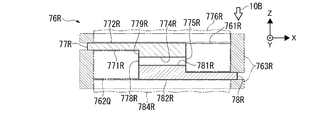
- FIG. 5A schematically illustrates a configuration of the second filter according to the second embodiment when viewed from the + Z direction side.
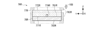
- FIG. 5B is a cross-sectional view taken along line BB in FIG. 5A.
- FIG. 5C schematically shows a configuration of the flow path of the second filter when viewed from the + Z direction side.
- the target supply device of the second embodiment may apply the same configuration as the target supply device 7A of the first embodiment, except for the second filter 76B.
- the second filter 76B may be a filter according to the present disclosure. As shown in FIGS. 5A and 5B, the second filter 76B may include a first member 77B and a second member 78B.
- the first and second members 77B and 78B may be formed in a substantially disc shape with a material having low reactivity with the target substance.
- the material having low reactivity with the target substance may be molybdenum or tungsten when the target substance is tin, or any of the materials shown in Table 1.
- the thickness dimension of the first and second members 77B and 78B may be about 300 ⁇ m.
- the diameters of the first and second members 77B and 78B may be about 5 mm.
- a substantially circular first through hole 773B penetrating in the Z-axis direction may be provided in the center of the first member 77B.
- the diameter of the first through hole 773B may be 900 ⁇ m.
- a groove 770B that is recessed in a circular shape may be formed on the first surface 771B on the + Z direction side of the first member 77B.
- the diameter of the groove portion 770B may be 2.1 mm.
- the depth dimension of the groove part 770B may be 3 ⁇ m or less.
- first spacer portions 7741B a plurality of first spacer portions 7741B, a plurality of second spacer portions 7742B, and a plurality of third spacer portions 7743B may be provided.
- the groove portion 770B and the first, second, and third spacer portions 7741B, 7742B, and 7743B may be formed by etching the first surface 771B of the first member 77B.
- the first spacer portion 7741B may be provided in a substantially annular region around the first through hole 773B.
- the shape of the first spacer portion 7741B when viewed from the + Z direction may be a substantially rectangular shape.
- the direction in which the first spacer portion 7741B extends when viewed from the + Z direction may be a direction substantially orthogonal to the rolling direction 760B of the first member 77B.
- the first spacer portion 7741B may be provided so as to be aligned in the rolling direction 760B.
- the first spacer portion 7741B may extend to the first through hole 773B.
- the second spacer portion 7742B may be provided in the + X direction side and ⁇ X direction side regions of the first spacer portion 7741B.
- the shape of the second spacer portion 7742B when viewed from the + Z direction may be substantially square.
- the second spacer portions 7742B may be scattered in the X-axis direction and the Y-axis direction.
- the third spacer portion 7743B may be provided in regions on the + Y direction side and the ⁇ Y direction side of the first spacer portion 7741B.
- the shape of the third spacer portion 7743B when viewed from the + Z direction may be a substantially linear shape in which the first through hole 773B side extends in the X-axis direction, and the opposite side to the first through hole 773B may be a substantially arc shape.
- the region between the first spacer portions 7741B adjacent to each other in the groove portion 770B can constitute a first flow path 774B1 extending in a direction substantially orthogonal to the rolling direction 760B.
- a region between the third spacer portion 7743B and the first spacer portion 7741B adjacent to each other in the groove portion 770B can constitute the first flow path 774B1.
- the first flow path 774B1 can be located on the + X direction side, the ⁇ X direction side, the + Y direction side, and the ⁇ Y direction side of the first through hole 773B. Note that the first flow path 774B1 may extend in an intersecting direction instead of a direction substantially orthogonal to the rolling direction 760B.
- the angle formed between the direction in which the first flow path 774B1 extends and the rolling direction 760B is not about 90 °, but may be an angle other than about 0 ° such as about 45 ° or about 60 °.
- a region between the second spacer portions 7742B adjacent to each other in the groove portion 770B can constitute a second flow path 774B2 formed in a lattice shape.
- a region between the third spacer portion 7743B and the second spacer portion 7742B adjacent to each other in the groove portion 770B can constitute a second flow path 774B2 extending linearly.
- the region outside the third spacer portion 7743B and the second spacer portion 7742B in the groove portion 770B can constitute the third flow path 774B3.
- the third flow path 774B3 can be formed in a substantially annular shape concentric with the first through hole 773B.
- the first flow path 774B1, the second flow path 774B2, and the third flow path 774B3 may constitute the flow path 774B.
- the width dimension of the first channel 774B1 and the second channel 774B2 may be 30 ⁇ m.
- the width dimensions of the first flow path 774B1 and the second flow path 774B2 may be different.
- the width dimension of the third channel 774B3 may be 200 ⁇ m.
- the depth dimension of the first, second, and third flow paths 774B1, 774B2, and 774B3 may be the same as the depth dimension of the groove portion 770B.
- the depth dimensions of the first, second, and third flow paths 774B1, 774B2, and 774B3 may be dimensions in a direction perpendicular to the first surface 771B.
- the depth dimensions of the first, second, and third flow paths 774B1, 774B2, and 774B3 may be smaller than the dimensions of the particles that have passed through the third porous filter 753A. Thereby, the flow path 774B can collect particles.
- the end of the first flow path 774B1 on the first through hole 773B side in the flow path 774B may be the first region 775B.
- the first through-hole 773B is formed between the first surface 771B and the first space 776B on the third surface 772B side opposite to the first surface 771B.
- region 775B can be comprised.
- the first through hole 773B may constitute a first flow part for causing the target material flowing into the first region 775B of the flow path 774B to flow out into the first space 776B.
- a flat surface portion 777B may be provided outside the flow path 774B on the first surface 771B of the first member 77B.
- the flat portion 777B may be provided in an annular shape surrounding the flow path 774B.
- the flat portion 777B may be an unetched region on the first surface 771B.
- the flat portion 777B and the third surface 772B may be polished.
- the second member 78B may be disposed so as to overlap the first member 77B.
- the second member 78B may be arranged such that the second surface 781B covers the flow path 774B of the first member 77B.
- the second member 78B may be provided with eight substantially circular second through holes 783B penetrating in the Z-axis direction.
- the diameter of the second through hole 783B may be 40 ⁇ m.
- the second through holes 783B may be provided at substantially equal intervals along the outer circumferential direction of the second member 78B. Accordingly, the second through hole 783B can be provided point-symmetrically with respect to the center of the second member 78B.
- the second through-hole 783B may be provided so as not to be positioned within the opening of the first through-hole 773B when the second member 78B is disposed so as to overlap the first member 77B. At this time, a part of the flow path 774B may be located in the opening of the second through hole 783B. A part of the flow path 774B located in the opening of the second through hole 783B may be the second region 778B. The second region 778B may include a third flow path 774B3.
- the second through hole 783B is interposed between the second surface 781B and the second space 784B on the fourth surface 782B side opposite to the second surface 781B via the second region 778B of the flow path 774B.
- circulating a target material can be comprised.
- the second through hole 783B can constitute a second flow part for allowing the target material existing in the second space 784B to flow into the second region 778B of the flow path 774B.
- the second surface 781B and the fourth surface 782B may be polished.
- FIG. 6 schematically shows a manufacturing method of the first member.
- FIG. 7 schematically shows a method for manufacturing the second member.
- a method for manufacturing the first member 77B will be described.
- a plate 100B formed of molybdenum may be prepared.
- the plate 100B may be formed by rolling bulk molybdenum.
- the vertical direction in FIG. 6 may substantially coincide with the rolling direction 760B of the plate 100B.
- the plate 100B may be a 100 mm square.
- Masking for forming the flow path 774B may be provided on the first surface 101B of the plate 100B. The masking may be configured such that the flow paths 774B of the plurality of first members 77B can be formed.
- the first surface 101B of the plate 100B may be etched by a wet etching method. Thereby, the first flow path 774B1 in FIG. 5C is formed on the first surface 101B, and a plurality of flow paths 774B can be formed.
- a cross-shaped marker 102B may be formed in the approximate center of the flow path 774B.
- a plurality of first members 77B may be cut out from the plate 100B. You may form the 1st through-hole 773B by giving a drilling process in the approximate center of the 1st member 77B. At this time, drilling may be performed using the marker 102B as a mark. Both surfaces of the first member 77B may be polished and cleaned. Thus, the manufacture of the first member 77B can be completed.
- the double-side polishing of the first member 77B may be performed prior to etching and drilling. Further, the drilling process may be performed prior to the etching.
- the first flow path 774B1 of the flow path 774B can extend in a direction substantially orthogonal to the rolling direction 760B.
- the etched surface may be roughened by the structure depending on the rolling direction 760B of the plate 100B. Due to this surface roughness, fine grooves extending along the rolling direction 760B can be formed on the bottom surface of the first flow path 774B1.
- the depth dimension of the portion where the fine groove is formed in the first flow path 774B1 may be larger than the depth dimension of the portion where the fine groove is not formed.
- the direction in which the first flow path 774B1 extends is parallel to the rolling direction 760B, fine grooves on the bottom surface can be continuously formed along the direction in which the first flow path 774B1 extends. Thereby, particles that can be collected in a portion where the fine groove is not formed in the first flow path 774B1 can pass through the portion where the fine groove is formed and flow into the first through hole 773A.
- the direction in which the first flow path 774B1 extends is substantially orthogonal to or intersects with the rolling direction 760B, the minute grooves extend from one side to the other side in the width direction of the bottom surface portion, and thus the first flow path 774B1 extends. It can suppress that the fine groove
- a plate 110B formed of molybdenum may be prepared.
- the plate 110B may be formed by the same method as the plate 100B.
- the plate 110B may be a 100 mm square.
- a plurality of second members 78B may be cut out from the plate 110B. You may form the 2nd through-hole 783B by giving a drilling process in the multiple places of the 2nd member 78B. Both surfaces of the second member 78B may be polished and cleaned. Thus, the manufacture of the second member 78B can be completed.
- the second member 78B may be disposed on the first member 77B so that the second surface 781B of the second member 78B covers the flow path 774B of the first member 77B.
- the first member 77B and the second member 78B may be diffusion bonded.
- the 2nd filter 76B which has the flow path 774B whose depth dimension is 3 micrometers or less can be manufactured.
- the second through-hole 783B is provided point-symmetrically with respect to the center of the second member 78B, the second through-hole is provided even if the arrangement position of the second member 78B with respect to the first member 77B is shifted in the rotation direction.
- the third flow path 774B3 is located in the opening of the hole 783B, and the target material can flow through the second filter 76B. Since the first and second surfaces 771B and 781B are polished, the gap between the first surface 771B and the second surface 781B can be reduced. In the second embodiment, diffusion bonding between the first member and the second member may not be essential.
- a second filter 76B may be attached between the nozzle base end portion 82A and the nozzle tip end portion 83A. Accordingly, the eight second through holes 783B of the second member 78B are positioned in the opening of the second through hole 822A, and the inside of the second through hole 822A can be the second space 784B.
- the first through hole 773B of the first member 77B is located in the opening on the + Z direction side of the third through hole 832A, and the inside of the third through hole 832A can be the first space 776B.
- the flow path 774B can be suppressed from being crushed even if pressure is applied to the fourth surface 782B. Thereafter, the target material may pass through the first through hole 773B and flow into the third through hole 832A.
- the direction in which the first flow path 774B1 extends is set to a direction substantially orthogonal to the rolling direction 760B or a direction intersecting with it, and thus a direction parallel to the rolling direction 760B. Compared to the case of setting to, fine particles can be collected.
- FIG. 8A schematically illustrates a configuration of the second filter according to the third embodiment viewed from the + Z direction side.
- FIG. 8B is a cross-sectional view taken along line BB in FIG. 8A.
- FIG. 8C schematically shows a configuration of the flow path of the second filter when viewed from the + Z direction side.
- the target supply device of the third embodiment may apply the same configuration as the target supply device 7A of the first embodiment, except for the second filter 76C.
- the second filter 76C may be a filter according to the present disclosure. As shown in FIGS. 8A and 8B, the second filter 76C may include a first member 77C and a second member 78B.
- the first member 77C may be formed in a substantially disc shape with a material having low reactivity with the target substance, similarly to the first member 77B.
- the thickness dimension of the first member 77C may be about 300 ⁇ m, for example.
- the diameter of the first member 77C may be about 5 mm, for example.
- a substantially circular first through hole 773C penetrating in the vertical direction may be provided in the center of the first member 77C.
- the diameter of the first through hole 773C may be 600 ⁇ m, for example.
- a first groove 770C1 and a second groove 770C2 may be formed on the first surface 771C on the + Z direction side of the first member 77C.
- the first groove portion 770C1 may have a circular shape with a diameter of 2.6 mm, for example.
- the second groove 770C2 may be provided so as to extend radially from the outer edge of the first groove 770C1.
- the second groove portions 770C2 may be provided at substantially equal intervals along the outer peripheral direction of the first groove portion 770C1.
- the depth dimension of the first and second groove portions 770C1 and 770C2 may be, for example, 3 ⁇ m or less.
- a plurality of first spacer portions 7741C and a plurality of second spacer portions 7742C may be provided inside the first groove portion 770C1.
- the first and second groove portions 770C1 and 770C2 and the first and second spacer portions 7741C and 7742C may be formed by etching the first surface 771C of the first member 77C.
- the first spacer portion 7741C may be provided in a substantially annular region around the first through hole 773C.
- the first spacer portion 7741C may be provided to extend radially from a position away from the first through hole 773C by a predetermined distance.
- the first spacer portions 7741C may be provided at substantially equal intervals along the outer peripheral direction of the first through hole 773C.
- the second spacer portion 7742C may be provided in a substantially annular region surrounding the first spacer portion 7741C.
- the second spacer portion 7742C may be provided to extend radially from a position away from the first spacer portion 7741C by a predetermined distance.
- the second spacer portions 7742C may be provided at substantially equal intervals along the outer peripheral direction of the first through hole 773C.
- the substantially annular region on the first through hole 773C side from the first spacer portion 7741C in the first groove portion 770C1 can constitute the first flow path 774C1.
- a region between the first spacer portions 7741C adjacent to each other in the first groove portion 770C1 can constitute a radial second flow path 774C2.
- a region between the first spacer portion 7741C and the second spacer portion 7742C adjacent to each other in the first groove portion 770C1 can form a substantially circular third flow path 774C3.
- a region between the second spacer portions 7742C adjacent to each other in the first groove portion 770C1 can constitute a radial fourth flow path 774C4.
- the substantially annular region outside the second spacer portion 7742C in the first groove portion 770C1 can constitute the fifth flow path 774C5.
- the second groove 770C2, the first channel 774C1, the second channel 774C2, the third channel 774C3, the fourth channel 774C4, and the fifth channel 774C5 may constitute the channel 774C.
- the width dimension of the second groove 770C2 may be, for example, 70 ⁇ m to 100 ⁇ m.
- the width dimension of the first flow path 774C1 may be 150 ⁇ m, for example.
- the width dimension of the second and third flow paths 774C2 and 774C3 may be, for example, 10 ⁇ m.
- the width dimension of the fourth flow path 774C4 may be, for example, 40 ⁇ m to 60 ⁇ m.
- the width dimension of the fifth channel 774C5 may be, for example, 100 ⁇ m.
- the depth dimension of the second groove 770C2 and the depth dimension of the first to fifth flow paths 774C1 to 774C5 may be the same as the depth dimension of the first groove 770C1.
- the depth dimension of the first to fifth flow paths 774C1 to 774C5 may be smaller than the dimension of the particles that have passed through the third porous filter 753A. Thereby, the flow path 774C can collect fine particles.
- the first channel 774C1 in the channel 774C may be the first region 775C.
- the first through hole 773C is formed between the first surface 771C and the first space 776C on the third surface 772C side opposite to the first surface 771C.
- region 775C can be comprised.
- the first through hole 773C may constitute a first flow part for causing the target material flowing into the first region 775C of the flow path 774C to flow out into the first space 776C. As shown in FIG.
- a flat surface portion 777C may be provided outside the flow path 774C on the first surface 771C of the first member 77C.
- the flat surface portion 777C may include an annular portion and a portion that extends radially from the inner edge of the annular shape.
- the flat portion 777C may be an unetched region on the first surface 771C.
- the flat portion 777C and the third surface 772C may be polished.
- the second through hole 783B of the second member 78B may be provided not to be positioned within the opening of the first through hole 773C when the second member 78B is disposed on the first member 77C. At this time, a part of the flow path 774C may be located in the opening of the second through hole 783B. A part of the flow path 774C located in the opening of the second through hole 783B may be the second region 778C.
- the second region 778C may include a part of the second groove 770C2 and the fourth and fifth flow paths 774C4 and 774C5.
- the second through hole 783B is interposed between the second surface 781B and the second space 784B on the fourth surface 782B side opposite to the second surface 781B via the second region 778C of the flow path 774C.
- circulating a target substance can be comprised.
- the 2nd through-hole 783B can comprise the 2nd circulation part similar to 2nd Embodiment.
- the first member 77C may be manufactured by the same method as the first member 77B except that a dry etching method is used instead of the wet etching method.
- the second member 78B may be placed over the first member 77C so that the second surface 781B of the second member 78B covers the flow path 774C of the first member 77C. At this time, the first member 77C and the second member 78B may be diffusion bonded.
- the 2nd filter 76C which has the flow path 774C whose depth dimension is 3 micrometers or less can be formed.
- the second through-hole 783B is provided point-symmetrically around the center of the second member 78B, even if the arrangement position of the second member 78B with respect to the first member 77C is shifted in the rotation direction, the second through-hole Part of the second groove 770C2 and the fourth and fifth flow paths 774C4 and 774C5 are located in the opening of the hole 783B, and the target material can flow through the second filter 76C. Since the first and second surfaces 771C and 781B are polished, the gap between the first surface 771C and the second surface 781B can be reduced. In the third embodiment, diffusion bonding between the first member and the second member may not be essential.
- a second filter 76C may be attached between the nozzle base end portion 82A and the nozzle tip end portion 83A. Accordingly, the eight second through holes 783B of the second member 78B are positioned in the opening of the second through hole 822A, and the inside of the second through hole 822A can be the second space 784B.
- the first through hole 773C of the first member 77C is located in the opening on the + Z direction side of the third through hole 832A, and the inside of the third through hole 832A can be the first space 776C.
- Target Supply Device When the pressure in the target generator 8A is adjusted in a state where the target generator 8A is heated to a temperature equal to or higher than the melting point of the target material, the particles are first
- the target material collected by the filter 75A can pass through the second filter 76C.
- the target material that has reached the second filter 76C can flow into the second through hole 783B of the second member 78B.
- the target material that has flowed into the second through-hole 783B flows through the channel 774C through the second groove 770C2, the fifth channel 774C5, the fourth channel 774C4, the third channel 774C3, the second channel 774C2, and the first channel. You can pass in the order of 774C1.
- the channel 774C can collect particles larger than the depth dimension of the channel 774C. Since the upper ends of the first and second spacer portions 7741C and 7742C are in contact with the second surface 781B, the flow path 774C can be suppressed from being crushed even if pressure is applied to the fourth surface 782B. Thereafter, the target material may pass through the first through hole 773C and flow into the third through hole 832A.
- a columnar spacer is arranged on the first surface, and the flow path is a region between adjacent spacers. It may be configured.
- the first member is disposed so that a part of the first surface protrudes from the second surface, and the flow path is formed to a position corresponding to the outer edge of the second member;
- the second circulation part may be configured by a side space facing a part of the first surface protruding from the second surface and the outer edge of the second member.
- FIG. 9A schematically illustrates a configuration of the second filter according to the fourth embodiment as viewed from the + Z direction side.
- FIG. 9B is a sectional view taken along line BB in FIG. 9A.
- the target supply device of the fourth embodiment may apply the same configuration as the target supply device 7A of the first embodiment, except for the second filter 76D.
- the second filter 76D may be a filter according to the present disclosure. As shown in FIGS. 9A and 9B, the second filter 76D may include a first member 77D and a second member 78D.
- the first and second members 77D and 78D may be formed in a substantially disk shape with a material having low reactivity with the target substance.
- the thickness dimension of the first and second members 77D and 78D may be about 300 ⁇ m, for example.
- the diameter of the first member 77D may be about 5 mm, for example.
- a substantially circular first through hole 773D penetrating in the vertical direction may be provided in the center of the first member 77D.
- a plurality of spacers 7741D may be arranged on the first surface 771D on the + Z direction side of the first member 77D.
- the spacer 7741D may be columnar.
- the spacer 7741D may be configured separately from the first member 77D, or may be configured integrally with the first member 77D.
- the spacers 7741D may be scattered in a substantially annular region centered on the first through-hole 773D.
- the region between the spacers 7741D adjacent to each other on the first surface 771D of the first member 77D can constitute a flow path 774D.
- the width dimension of the flow path 774D may be, for example, 10 ⁇ m to 150 ⁇ m.
- the depth dimension of the channel 774D may be, for example, 3 ⁇ m or less. Thereby, the flow path 774D can collect fine particles.
- the first surface 771D and the third surface 772D may be polished.
- the diameter of the second member 78D may be smaller than the diameter of the first member 77D. Accordingly, the first member 77D can be arranged such that a part of the first surface 771D protrudes from the second surface 781D.
- the second member 78D may be provided such that the plurality of spacers 7741D are in contact with the second surface 781D on the ⁇ Z direction side when the second member 78D is disposed so as to overlap the spacer 7741D of the first member 77D.
- the end of the flow path 774D on the first through hole 773D side may be the first region 775D. Accordingly, as shown in FIG. 9B, the first through hole 773D is formed between the first surface 771D and the first space 776D on the third surface 772D side opposite to the first surface 771D.
- region 775D can be comprised.
- the first through hole 773D may constitute a first flow part for causing the target material flowing into the first region 775D of the flow path 774D to flow out into the first space 776D.
- the end of the second member 78D on the outer edge side in the flow path 774D may be the second region 778D.
- the side space 762D facing the portion of the first surface 771D that protrudes outside the second surface 781D and the outer edge of the second member 78D is formed on the opposite side of the second surface 781D and the second surface 781D.
- a second flow part for flowing the target material through the second region 778D of the flow path 774D can be configured between the second space 784D on the fourth surface 782D side.
- the side space 762D may constitute a second flow part for allowing the target material existing in the second space 784D to flow into the second region 778D of the flow path 774D.
- the second surface 781D and the fourth surface 782D may be polished.
- the first member 77D in which the first through hole 773D is formed may be manufactured.
- the flow path 774D may be formed by arranging the spacer 7741D on the first surface 771D of the first member 77D.
- the second member 78D may be manufactured.
- the second member 78D may be overlaid on the first member 77D so that the second surface 781D of the second member 78D covers the flow path 774D of the first member 77D.
- the first member 77D and the second member 78D may be diffusion bonded.
- the second filter 76D having the flow path 774D having a depth dimension of, for example, 3 ⁇ m or less can be formed.
- a second filter 76D may be attached between the nozzle base end portion 82A and the nozzle tip end portion 83A. Thereby, the side space 762D of the second filter 76D can be positioned in the opening of the second through hole 822A, and the inside of the second through hole 822A can be the second space 784D.
- the first through hole 773D of the first member 77D is located in the opening on the + Z direction side of the third through hole 832A, and the inside of the third through hole 832A can be the first space 776D.
- Target Supply Device When the pressure in the target generator 8A is adjusted while the target generator 8A is heated to a temperature equal to or higher than the melting point of the target material, particles are first
- the target material collected by the filter 75A can pass through the second filter 76D.
- the target material that has reached the second filter 76D can flow into the flow path 774D through the side space 762D.
- the flow path 774D can collect particles larger than the depth dimension of the flow path 774D. Since the upper end of the spacer 7741D is in contact with the second surface 781D, the channel 774D can be prevented from being crushed even if pressure is applied to the fourth surface 782D.
- the target material may pass through the first through hole 773D and flow into the third through hole 832A.
- the channel 774D since the channel 774D is configured in the region between the spacers 7741D adjacent to each other, the channel 774D can be easily formed without drilling the first member 77D.
- the second circulation portion is configured by the side space 762D facing the outside of the second surface 781D of the first surface 771D and the outer edge of the second member 78D, the second member 78D is drilled.
- the second circulation part can be easily formed without any problem.
- the second through hole may be formed so as to penetrate substantially the center of the second member.
- the second member is disposed such that a part of the second surface protrudes from the first surface, and the flow path is formed up to the outer edge of the first member. May be constituted by a side space facing a part of the second surface protruding from the first surface and the outer edge of the first member.
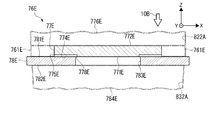
- FIG. 10A schematically illustrates a configuration of the second filter according to the fifth embodiment when viewed from the + Z direction side.
- FIG. 10B is a cross-sectional view taken along line BB in FIG. 10A.
- the same configuration as the target supply device 7A of the first embodiment may be applied except for the configuration of the second filter 76E.
- the second filter 76D may be a filter according to the present disclosure.
- the second filter 76E may include a first member 77E and a second member 78E, as shown in FIGS. 10A and 10B.
- the first member 77E and the second member 78E may be formed in a substantially disc shape.
- a plurality of flow paths 774E may be formed on the first surface 771E on the ⁇ Z direction side of the first member 77E.
- the flow path 774E may be configured by a groove formed in the first surface 771E.
- the flow path 774E may be provided so that the outer edge of the first member 77E communicates with a through hole 783E described later.
- the flow paths 774E may be provided radially.
- the depth dimension of the flow path 774E may be 3 ⁇ m or less, for example. Thereby, the flow path 774E can collect particles.
- the diameter of the second member 78E may be larger than the diameter of the first member 77E. Accordingly, the second member 78E can be arranged such that a part of the second surface 781E protrudes from the first surface 771E.
- the second member 78E may be disposed so as to overlap the lower side of the first member 77E.
- the second member 78E may be arranged such that the second surface 781E covers the flow path 774E.
- a substantially circular through hole 783E may be provided in the center of the second member 78E.
- the through hole 783E may be the second through hole of the present disclosure.
- the end portion on the outer edge side of the second member 78E in the flow path 774E may be the first region 775E.
- the side space 761E facing the portion of the second surface 781E that protrudes outside the first surface 771E and the outer edge of the first member 77E is the first surface 771E and the side opposite to the first surface 771E.
- a first flow part for flowing the target material between the first space 776E on the third surface 772E side and the first region 775E of the flow path 774E can be configured.
- the side space 761E can constitute a first flow part for allowing the target material existing in the first space 776E to flow into the first region 775E of the flow path 774E.
- the end of the flow path 774E on the through hole 783E side may be the second region 778E.
- the through hole 783E allows the target material to pass between the second surface 781E and the second space 784E on the fourth surface 782E side opposite to the second surface 781E via the second region 778E of the flow path 774E.
- the 2nd distribution part for distributing can be constituted.
- the through hole 783E can constitute a second flow part for allowing the target material flowing into the second region 778E of the flow path 774E to flow out into the second space 784E.
- the first member 77E in which the flow path 774E is formed may be manufactured. You may manufacture the 2nd member 78E in which the through-hole 783E was formed. The first member 77E may be placed on the second member 78E so that the second surface 781E of the second member 78E covers the flow path 774E of the first member 77E. At this time, the first member 77E and the second member 78E may be diffusion bonded. Thereby, the 2nd filter 76E which has the flow path 774E whose depth dimension is 3 micrometers or less, for example can be formed.
- a second filter 76E may be attached between the nozzle base end portion 82A and the nozzle tip end portion 83A.
- the side space 761E of the second filter 76E is positioned in the opening of the second through hole 822A, and the inside of the second through hole 822A can be the first space 776E.
- the through hole 783E of the second member 78E is located in the opening on the + Z direction side of the third through hole 832A, and the inside of the third through hole 832A can be the second space 784E.
- the first flow portion is configured by the side space 761E facing the portion of the second surface 781E that protrudes outside the first surface 771E and the outer edge of the first member 77E.
- the first flow part can be easily formed without drilling the one member 77E.
- the first member is a first plate-like member and a second plate arranged so as to overlap the first plate-like member.
- the flow path may be constituted by a third through hole that penetrates the second plate-like member.
- FIG. 11A schematically illustrates a configuration of the second filter according to the sixth embodiment when viewed from the + Z direction side.
- FIG. 11B is a cross-sectional view taken along line BB in FIG. 11A.
- FIG. 11C schematically shows a modification of the flow path of the second filter.
- the target supply device of the sixth embodiment may apply the same configuration as the target supply device 7A of the first embodiment, except for the second filter 76F.
- the second filter 76F may be a filter according to the present disclosure.
- the second filter 76F may include a first member 77F and a second member 78F, as shown in FIGS. 11A and 11B.
- the first and second members 77F and 78F may be formed in a substantially disc shape with a material having low reactivity with the target substance.
- the thickness dimension of the first and second members 77F and 78F may be about 300 ⁇ m, for example.
- the diameters of the first and second members 77F and 78F may be about 5 mm, for example.
- the first member 77F may include a first plate member 77F1 and a second plate member 77F2.
- the thickness dimension of the first plate-like member 77F1 may be smaller than the thickness dimension of the second member 78F.
- a first through hole 773F penetrating in the vertical direction may be provided in the center of the first plate-like member 77F1.
- the thickness dimension of the second plate member 77F2 may be, for example, 3 ⁇ m or less.
- the second plate-like member 77F2 may be provided with, for example, eight third through-holes 7741F having a slit shape penetrating in the vertical direction.
- the third through hole 7741F may be provided so as to extend radially from a position away from the center of the second plate-like member 77F2.
- the third through holes 7741F may be provided at substantially equal intervals along the outer peripheral direction of the second plate-like member 77F2. Thereby, the third through hole 7741F can be provided point-symmetrically around the center of the second plate-like member 77F2.
- the second plate member 77F2 may be disposed on the surface on the + Z direction side of the first plate member 77F1.
- the 3rd through-hole 7741F can comprise channel 774F whose depth dimension is 3 micrometers or less, for example.
- the flow path 774F can collect particles.
- the end on the center side of the second plate-like member 77F2 in the flow path 774F may be the first region 775F.
- the first through hole 773F is formed between the first surface 771F of the first member 77F and the first space 776F on the third surface 772F side opposite to the first surface 771F.
- region 775F can be comprised.
- the first through hole 773F may constitute a first flow part for causing the target material flowing into the first region 775F of the flow path 774F to flow out into the first space 776F.
- a flat surface portion 777F may be provided outside the flow path 774F on the first surface 771F of the first member 77F.
- the second member 78F may be disposed so as to overlap the upper side of the first member 77F.
- the second member 78F may be arranged such that the second surface 781F covers the flow path 774F of the first member 77F.
- the second member 78F may be provided with eight substantially circular second through holes 783F penetrating in the vertical direction.
- the second through holes 783F may be provided at substantially equal intervals along the outer circumferential direction of the second member 78F. Accordingly, the second through hole 783F can be provided point-symmetrically around the center of the second member 78F.
- the second through hole 783F may be provided so as not to be positioned within the opening of the first through hole 773F when the second member 78F is disposed on the first member 77F.
- a part of the flow path 774F may be located in the opening of the second through hole 783F.
- a part of the flow path 774F located in the opening of the second through hole 783F may be the second region 778F.
- the second through hole 783F is interposed between the second surface 781F and the second space 784F on the fourth surface 782F side opposite to the second surface 781F via the second region 778F of the flow path 774F.
- circulating a target substance can be comprised.
- the second through hole 783F may constitute a second flow part for allowing the target material existing in the second space 784F to flow into the second region 778F of the flow path 774F.
- the flow path 774F may be formed in a crank shape as shown in FIG. 11C.
- the corner portion 774F1 in the flow path 774F may be formed so as to protrude outward in a substantially circular shape. Thereby, particles are collected in the corner portion 774F1, and clogging of the flow path 774F by the particles can be suppressed.
- FIG. 12 schematically shows a manufacturing method of the second filter.
- a first plate member 77F1 made of molybdenum may be prepared.
- the first plate member 77F1 may be cut out from a plate having a size capable of obtaining a plurality of first plate members 77F1.
- the 2nd plate-shaped member 77F2 and the 2nd member 78F which are mentioned later may be similarly cut out from a big plate. You may form the 1st through-hole 773F by giving a drilling process to the approximate center of the 1st plate-shaped member 77F1.
- Both surfaces of the first plate member 77F1 may be polished and cleaned.
- the first plate member 77F1 can be manufactured.
- the second plate member 77F2 can be manufactured.
- a second member 78F made of molybdenum may be prepared.
- the second through hole 783F may be formed by drilling a plurality of locations of the second member 78F. Both surfaces of the second member 78F may be polished and cleaned. Thus, the second member 78F can be manufactured.
- the second plate member 77F2 may be disposed so as to overlap the first plate member 77F1 to form the first member 77F.
- the second member 78F may be placed on the first member 77F so that the second surface 781F of the second member 78F covers the flow path 774F of the first member 77F.
- the first member 77F and the second member 78F may be diffusion bonded.
- the 2nd filter 76F which has the flow path 774F whose depth dimension is 3 micrometers or less can be manufactured.
- the second through-hole 783F is provided point-symmetrically with respect to the center of the second member 78F, even if the position of the second member 78F relative to the first member 77F is slightly shifted in the rotational direction, A flow path 774F is located in the opening of the through hole 783F, and the target material can flow through the second filter 76F. Since the first and second surfaces 771F and 781F are polished, the gap between the first surface 771F and the second surface 781F can be reduced. Since the joint surface between the first plate member 77F1 and the second plate member 77F2 is polished, the gap between the first plate member 77F1 and the second plate member 77F2 can be reduced. In the sixth embodiment, diffusion bonding between the first member and the second member may not be essential.
- a second filter 76F may be attached between the nozzle base end portion 82A and the nozzle tip end portion 83A. Accordingly, the eight second through holes 783F of the second member 78F are positioned in the opening of the second through hole 822A, and the inside of the second through hole 822A can become the second space 784F.
- the first through hole 773F of the first member 77F is located in the opening on the + Z direction side of the third through hole 832A, and the inside of the third through hole 832A can be the first space 776F.
- the flow path 774E is configured by the third through hole 7741F that penetrates the second plate-shaped member 77F2, the flow path 774E is easily formed as compared with the case where the groove is formed. Can do.
- the second member is disposed on the output direction side of the target material with respect to the first member, and the second circulation unit May be constituted by a second through hole penetrating the second member, and an opening on the output direction side of the second through hole may constitute a nozzle hole.
- FIG. 13A schematically illustrates a main part of a target supply device according to a seventh embodiment.
- FIG. 13B is a cross-sectional view taken along line BB in FIG. 13A.
- the target supply device of the seventh embodiment may apply the same configuration as the target supply device 7A of the first embodiment, except for the target generator 8G and the filter 76G.
- the target generator 8G may or may not include the first filter 75A. As shown in FIGS. 13A and 13B, the target generator 8G may include a nozzle base end portion 82G provided at the front end of a tank (not shown) and a nozzle front end portion 83G.
- the nozzle base end portion 82G and the nozzle tip end portion 83G may be made of a material having low reactivity with the target substance.
- a second through hole 822G penetrating in the Z-axis direction may be provided in the center of the nozzle base end portion 82G.
- the inner diameter of the second through hole 822G may be 3 mm, for example.
- a concave portion 827G may be provided at the tip of the nozzle base end portion 82G.
- the nozzle tip 83G may be formed in a substantially cylindrical shape, and the outer dimension of the planar portion may be formed larger than the diameter of the second through hole 822G.
- a recess 831G may be provided on the upper surface of the nozzle tip 83G.
- a conical hole 834G penetrating in the vertical direction may be provided at the center of the nozzle tip 83G.
- the conical hole 834G may be formed in a conical shape having a diameter that increases in the ⁇ Z direction.
- the filter 76G may be provided so as to close the second through hole 822G at the tip of the nozzle base end portion 82G.
- the filter 76G may include a first member 77G and a second member 78G.
- the first and second members 77G and 78G may be formed in a substantially disk shape with a material having low reactivity with the target substance.
- the diameters of the first and second members 77G and 78G may be larger than the diameter of the second through hole 822G.
- the first member 77G may be provided with, for example, eight substantially circular first through holes 773G penetrating in the vertical direction.
- the first through holes 773G may be provided at substantially equal intervals along the outer circumferential direction of the first member 77G. Accordingly, the first through hole 773G can be provided point-symmetrically with respect to the center of the first member 77G.
- a substantially circular first flow path 774G1 may be provided on the first surface 771G on the ⁇ Z direction side of the first member 77G.
- the first flow path 774G1 may be provided at the center of the first surface 771G.
- a second flow path 774G2 may be provided on the first surface 771G.
- the second flow path 774G2 may be provided so as to extend radially from the outer edge of the first flow path 774G1 toward the first through hole 773G.
- the first and second flow paths 774G1 and 774G2 may be configured by grooves formed in the first surface 771G.
- the second flow paths 774G2 may be provided at substantially equal intervals along the outer peripheral direction of the first member 77G. Thereby, the second flow path 774G2 can be provided point-symmetrically with respect to the center of the first member 77G.
- the first channel 774G1 and the second channel 774G2 may constitute the channel 774G.
- the depth dimension of the second channel 774G2 may be smaller than the depth dimension of the first channel 774G1.
- the depth dimension of the second flow path 774G2 may be 3 ⁇ m or less, for example. Thereby, the flow path 774G can collect particles.
- region 775G may be sufficient as the edge part by the side of the 1st through-hole 773G in the flow path 774G. Accordingly, the first through hole 773G is formed between the first surface 771G of the first member 77G and the first space 776G on the third surface 772G side opposite to the first surface 771G.
- region 775G can be comprised.
- the first through hole 773G may constitute a first flow part for allowing the target material existing in the first space 776G to flow into the first region 775G of the flow path 774G.
- the first surface 771G and the third surface 772G may be polished.
- the second member 78G may be disposed so as to overlap the first member 77G.
- the second member 78G may be arranged such that the second surface 781G on the + Z direction side covers the flow path 774G of the first member 77G.
- a second through hole 783G penetrating in the Z-axis direction may be provided at the center of the second member 78G.
- the second through hole 783G may be formed in a conical shape having a diameter that increases in the ⁇ Z direction.
- the upper opening of the second through hole 783G may constitute a nozzle hole 785G.
- the diameter of the nozzle hole 785G may be, for example, 1 ⁇ m to 3 ⁇ m.
- the second through-hole 783G may be provided so as not to be positioned within the opening of the first through-hole 773G when the second member 78G is disposed so as to overlap the first member 77G. At this time, a part of the flow path 774G may be located in the opening of the nozzle hole 785G of the second through hole 783G. A part of the flow path 774G located in the opening of the second through hole 783G may be the second region 778G. Accordingly, the second through hole 783G is interposed between the second surface 781G and the second space 784G on the fourth surface 782G side opposite to the second surface 781G via the second region 778G of the flow path 774G.
- circulating a target substance can be comprised.
- the second through hole 783G may constitute a second flow part for allowing the target material flowing into the second region 778G of the flow path 774G to flow out into the second space 784G.
- the second surface 781G and the fourth surface 782G may be polished.
- the first member 77G and the second member 78G are diffusion bonded so that the flow path 774G of the first member 77G is covered with the second surface 781G of the second member 78G. May be. Thereby, a filter 76G having a flow path 774G having a depth dimension of 3 ⁇ m or less at the shallowest portion can be formed. Since the first and second surfaces 771G and 781G are polished, the gap between the first surface 771G and the second surface 781G can be reduced. In the seventh embodiment, diffusion bonding between the first member and the second member may not be essential.
- the filter 76G may be inserted into the recess 831G of the nozzle tip portion 83G, and the nozzle tip portion 83G may be attached to the nozzle base end portion 82G with a bolt (not shown).
- the first member 77G may be inserted into the recess 827G.
- the second member 78G may be disposed on the ⁇ Z direction side with respect to the first member 77G. Accordingly, the eight first through holes 773G of the first member 77G can be positioned within the opening of the second through hole 822G, and the inside of the second through hole 822G can be the first space 776G.
- the second through-hole 783G of the second member 78G is located in the opening on the + Z direction side of the conical hole 834G, and the inside of the conical hole 834G can be the second space 784G.
- the target material is filtered. Can pass 76G.
- the target material that has reached the filter 76G can pass through the flow path 774G via the first through hole 773G. At this time, the flow path 774G can collect particles larger than the depth dimension of the flow path 774G.
- the target control device may adjust the pressure in the target generator 8G to output the target material as the droplet 27 from the nozzle hole 785G.
- the filter 76G since the nozzle hole 785G is configured by the output direction side opening of the target material in the second through-hole 783G, the filter 76G has the function of collecting particles and the function of the nozzle. Can have.
- FIG. 14 schematically illustrates a main part of a target supply device according to an eighth embodiment.
- the target supply device of the eighth embodiment may apply the same configuration as the target supply device of the seventh embodiment, except for the second member 78H of the filter 76H that constitutes the target generator 8H.
- the second member 78H of the filter 76H may be formed in a substantially disc shape with a material having low reactivity with the target substance.
- the second member 78H may be arranged such that the second surface 781H on the + Z direction side covers the flow path 774G of the first member 77G.
- a frustoconical protrusion 786H may be provided at the center of the fourth surface 782H on the ⁇ Z direction side of the second member 78H.
- the protrusion 786H may be provided to make it easier for the electric field to concentrate on the protrusion 786H when a droplet is generated using an electric field.
- a second through hole 783H penetrating in the Z-axis direction may be provided at the center of the second member 78H.
- the second through hole 783H may be formed in a conical shape whose diameter is reduced toward the ⁇ Z direction.
- the opening in the ⁇ Z direction side of the second through-hole 783H and the opening in the center of the tip of the protrusion 786H may constitute the nozzle hole 785H.
- the diameter of the nozzle hole 785H may be, for example, 1 ⁇ m to 3 ⁇ m.
- the second through-hole 783H may be provided so as not to be positioned within the opening of the first through-hole 773G when the second member 78H is disposed so as to overlap the first member 77G.
- a part of the flow path 774G may be located in the opening of the second through hole 783H.
- a part of the flow path 774G located in the opening of the second through hole 783H may be the second region 778G.
- the second through hole 783H is interposed between the second surface 781H and the second space 784H on the fourth surface 782H side opposite to the second surface 781H via the second region 778G of the flow path 774G.
- circulating a target substance can be comprised.
- the second through hole 783H may constitute a second flow part for allowing the target material flowing into the second region 778G of the flow path 774G to flow out into the second space 784H.
- the second surface 781H and the fourth surface 782H may be polished.
- the first member 77G and the second member 78H are diffusion bonded so that the flow path 774G of the first member 77G is covered with the second surface 781H of the second member 78H. May be.
- a filter 76H having a flow path 774G having a depth dimension of 3 ⁇ m or less at the shallowest portion can be formed. Since the first and second surfaces 771G and 781H are polished, the gap between the first surface 771G and the second surface 781H can be reduced.
- the filter 76H may be attached so as to be sandwiched between the nozzle base end portion 82G and the nozzle tip end portion 83G.
- the second member 78H may be disposed on the ⁇ Z direction side with respect to the first member 77G. Accordingly, the second through hole 783H of the second member 78H is positioned inside the conical hole 834G, and the inside of the conical hole 834G can be the second space 784H.
- Target Supply Device When the pressure in the target generator 8H is adjusted while the target generator 8H is heated to a temperature equal to or higher than the melting point of the target material, the target material is filtered. 76H can be passed. The target material that has reached the filter 76H can pass through the flow path 774G via the first through hole 773G. At this time, the flow path 774G can collect particles larger than the depth dimension of the flow path 774G. Thereafter, the target control device may adjust the pressure in the target generator 8H to output the target material as the droplet 27 from the nozzle hole 785H.
- FIG. 15A schematically illustrates a main part of a target supply device according to a ninth embodiment.
- FIG. 15B is a sectional view taken along line BB in FIG. 15A.
- the target supply device of the ninth embodiment may apply the same configuration as the target supply device of the seventh embodiment, except for the filter 76J constituting the target generator 8J.
- the target generator 8J may include a nozzle base end portion 82G and a pipe 84J.
- the pipe 84J may be made of a material having low reactivity with the target substance.
- the inner diameter of the through hole 841J of the pipe 84J may be substantially equal to the inner diameter of the second through hole 822G of the nozzle base end portion 82G.
- the + Z side end of the pipe 84J may be inserted into the concave portion 827G of the nozzle base end portion 82G.
- the + Z side end face of the pipe 84J and the surface of the recess 827G of the nozzle base end part 82G may be polished so as to be sealable when the pipe 84J is inserted into the recess 827G.
- the filter 76J may be provided so as to close the through hole 841J at the tip of the pipe 84J.
- the filter 76J may include a first member 77J and a second member 78J.
- the first and second members 77J and 78J may be formed of a material having low reactivity with the target substance.
- the outer shape of the first and second members 77J and 78J may be larger than the diameter of the through hole 841J.
- first through holes 773G may be provided in the first member 77J.
- a flow path 774J may be provided on the first surface 771J on the ⁇ Z direction side of the first member 77J.
- the flow path 774J may be configured by a groove formed in the first surface 771J.
- the flow path 774J may be provided so as to extend radially from the center of the first surface 771J toward the first through hole 773G.
- the depth dimension of the flow path 774J may be, for example, 3 ⁇ m or less. Thereby, the flow path 774J can collect particles.
- region 775G may be sufficient as the edge part by the side of the 1st through-hole 773G in the flow path 774J. Accordingly, the first through-hole 773G is formed between the first surface 771J of the first member 77J and the first space 776J on the third surface 772J side opposite to the first surface 771J.
- region 775J can be comprised.
- the first through hole 773G can constitute a first flow part for allowing the target material existing in the first space 776J to flow into the first region 775J of the flow path 774J.
- the first surface 771J and the third surface 772J may be polished.
- the second member 78J may include a plate-like portion 787J and a tubular portion 788J.
- the plate-like portion 787J may be formed in a substantially disc shape.
- the outer diameter of the plate-like portion 787J may be larger than the outer diameter of the first member 77J.
- a protrusion 786H may be provided at the center of the fourth surface 782J on the ⁇ Z direction side in the plate-like portion 787J.
- a second through hole 783H may be provided in the center of the plate-like portion 787J.
- the lower opening of the second through hole 783H may constitute a nozzle hole 785H.
- the cylindrical portion 788J may be provided at an end portion on the outer side in the surface direction of the plate-like portion 787J.
- the first member 77J may be arranged inside the second member 78J so that the second surface 781J on the + Z direction side covers the flow path 774J of the first member 77J.
- the outer peripheral surface of the first member 77J and the inner peripheral surface of the cylindrical portion 788J may be sealed.
- the first surface 771J and the second surface 781J may be sealed.
- the second through hole 783H may be provided so as not to be positioned within the opening of the first through hole 773G when the first member 77J is disposed in the second member 78J.
- a part of the flow path 774J may be located in the opening of the second through hole 783H.
- a part of the flow path 774J located in the opening of the second through hole 783H may be the second region 778J. Accordingly, the second through-hole 783H is interposed between the second surface 781J and the second space 784J on the fourth surface 782J side opposite to the second surface 781J via the second region 778J of the flow path 774J.
- circulating a target substance can be comprised.
- the second through hole 783H may constitute a second flow part for causing the target material flowing into the second region 778J of the flow path 774J to flow out into the second space 784J.
- a pipe 84J may be disposed on the third surface 772J side of the first member 77J.
- the outer peripheral surface of the pipe 84J and the inner peripheral surface of the cylindrical portion 788J may be sealed.
- the third surface 772J and the second surface 781J may be polished.
- the end surface on the ⁇ Z side of the pipe 84J may be polished.
- the inner peripheral surface of the fourth surface 782J may be polished.
- the inner peripheral surface of the cylindrical portion 788J may be polished.
- the first member 77J may be disposed in the second member 78J so that the flow path 774J of the first member 77J is covered with the second surface 781J of the second member 78J.
- the filter 76J having the flow path 774J having a depth dimension of 3 ⁇ m or less can be formed.
- the pipe 84J may be disposed in the second member 78J.
- the second member 78J of the filter 76J may be attached to the nozzle base end portion 82G with a bolt (not shown).
- the pipe 84J may be inserted into the recess 827G.
- the second member 78J may be disposed on the ⁇ Z direction side with respect to the first member 77J.
- the eight first through holes 773G of the first member 77J are positioned in the opening of the through hole 841J, and the inside of the through hole 841J can be the first space 776J.
- the second through hole 783H of the second member 78J is located on the ⁇ Z direction side of the plate-like portion 787J, and the position on the ⁇ Z direction side can be the second space 784J.
- the first member is disposed on the output direction side of the target material with respect to the second member, It is comprised by the 1st through-hole which penetrates 1 member, and the opening of the output direction side of a 1st through-hole may comprise a nozzle hole.
- FIG. 16 schematically illustrates a main part of a target supply device according to the tenth embodiment.
- the target supply device of the tenth embodiment may apply the same configuration as the target supply device of the seventh embodiment, except for the filter 76K that constitutes the target generator 8K.
- the filter 76K may include a first member 77K and a second member 78K.
- the first member 77K and the second member 78K may be formed in a substantially disc shape.
- a frustoconical protrusion 793K may be provided at the center of the third surface 772K on the ⁇ Z direction side of the first member 77K.
- a first through hole 773K may be provided in the center of the first member 77K.
- the opening in the ⁇ Z direction side of the first through-hole 773K and the center of the tip of the protruding portion 793K may constitute a nozzle hole 794K.
- the diameter of the nozzle hole 794K may be, for example, 1 ⁇ m to 3 ⁇ m.
- eight channels 774K may be provided on the first surface 771K on the + Z direction side of the first member 77K.
- the flow path 774K may be configured by a groove formed in the first surface 771K.
- the channel 774K may be provided so as to extend radially from the center of the first surface 771K, similarly to the channel 774F illustrated in FIG. 11A.
- the flow paths 774K may be provided at substantially equal intervals along the outer peripheral direction of the first member 77K.
- the depth dimension of the channel 774K may be, for example, 3 ⁇ m or less.
- the portion communicating with the first through hole 773K in the flow path 774K may be the first region 775K.
- the first through hole 773K is formed between the first surface 771K of the first member 77K and the first space 776K on the third surface 772K side opposite to the first surface 771K.
- region 775K can be comprised.
- the first through hole 773K may constitute a first flow part for causing the target material flowing into the first region 775K of the flow path 774K to flow out into the first space 776K.
- the second member 78K may be arranged so as to overlap the upper side of the first member 77K.
- the second member 78K may be arranged such that the second surface 781K covers the flow path 774K.
- the second member 78K may be provided with eight substantially circular second through holes 783K.
- the second through holes 783K may be provided at substantially equal intervals along the outer circumferential direction of the second member 78K.
- the second through hole 783K may be provided so as not to be positioned within the opening of the first through hole 773K.
- a second region 778K that is an end portion of the flow path 774K may be positioned in the opening of the second through hole 783K.
- the second through-hole 783K is interposed between the second surface 781K and the second space 784K on the fourth surface 782K side opposite to the second surface 781K via the second region 778K of the flow path 774K.
- circulating a target substance can be comprised.
- the second through hole 783K may constitute a second flow part for allowing the target material existing in the second space 784K to flow into the second region 778K of the flow path 774K.
- the first member 77K and the second member 78K may be diffusion-bonded so that the flow path 774K of the first member 77K is covered with the second surface 781K of the second member 78K. Thereby, the filter 76K having the flow path 774K having a depth dimension of 3 ⁇ m or less can be formed.
- a filter 76K may be attached between the nozzle tip portion 83G and the nozzle base end portion 82G.
- the first member 77K may be disposed on the ⁇ Z direction side with respect to the second member 78K.
- the second through hole 783K of the second member 78K is positioned in the opening of the second through hole 822G, and the inside of the second through hole 822G can be the second space 784K.
- the first through hole 773K of the first member 77K is located in the opening on the + Z direction side of the conical hole 834G, and the inside of the conical hole 834G can be the first space 776K.
- the filter 76K since the nozzle hole 794K is configured by the opening in the output direction side of the target material in the first through hole 773K, the filter 76K has the function of collecting particles and the function of the nozzle. Can have.
- the filter may have the following configuration.
- the first and second members may be formed of a material having low reactivity with the target substance.
- the depth dimension of the flow path may be, for example, 3 ⁇ m or less.
- the ⁇ Z direction may coincide with the gravity direction 10B.
- FIG. 17A schematically illustrates a configuration of a filter according to a first modification as viewed from the + Z direction side.
- FIG. 17B is a cross-sectional view taken along line BB in FIG. 17A.
- the filter 76L may include a first member 77L and a second member 78L, as shown in FIGS. 17A and 17B.
- the first member 77L and the second member 78L may be formed in a substantially disk shape.
- a plurality of first through holes 773L may be provided in the first member 77L.
- the first through holes 773L may be arranged in a staggered manner.
- a flow path 774L may be formed in the first surface 771L on the ⁇ Z direction side of the first member 77L.
- the flow path 774L may be provided so as to communicate between the first through hole 773L and a second through hole 783L, which will be described later, adjacent to the first through hole 773L.
- the end of the flow path 774L on the first through hole 773L side may be the first region 775L. Accordingly, the first through hole 773L is interposed between the first surface 771L and the first space 776L on the third surface 772L side opposite to the first surface 771L via the first region 775L of the flow path 774L.
- circulating a target material can be comprised.
- the second member 78L may be disposed so as to overlap the ⁇ Z direction side of the first member 77L.
- the second member 78L may be arranged such that the second surface 781L covers the flow path 774L.
- a plurality of second through holes 783L may be provided in the second member 78L.
- the second through hole 783L may be provided at a position corresponding to between the first through holes 773L adjacent to each other.
- the second through hole 783L may be provided so as not to be positioned within the opening of the first through hole 773L when the first member 77L is disposed on the second member 78L.
- the second region 778L of the flow path 774L may be positioned in the opening of the second through hole 783L.
- the second through hole 783L is interposed between the second surface 781L and the second space 784L on the fourth surface 782L side opposite to the second surface 781L via the second region 778L of the flow path 774L.
- circulating a target material can be comprised.
- FIG. 18A schematically illustrates a configuration of a filter according to a second modification as viewed from the + Z direction side.
- 18B is a cross-sectional view taken along line BB in FIG. 18A.
- the filter 76M may include a first member 77M and a second member 78M.
- the first member 77M and the second member 78M may be formed in a substantially disc shape.
- eight first through holes 773M may be provided in the first member 77M.
- the first through holes 773M may be provided at substantially equal intervals along the outer peripheral direction of the first member 77M.
- a flow path 774M may be formed in the first surface 771M on the ⁇ Z direction side of the first member 77M.
- the flow path 774M may be provided so as to communicate the first through hole 773M and a second through hole 783M described later.
- the end of the flow path 774M on the first through hole 773M side may be the first region 775M. Accordingly, the first through hole 773M is interposed between the first surface 771M and the first space 776M on the third surface 772M side opposite to the first surface 771M via the first region 775M of the flow path 774M.
- circulating a target material can be comprised.
- the second member 78M may be arranged so as to overlap from the ⁇ Z direction side of the first member 77M.
- the second member 78M may be arranged such that the second surface 781M covers the flow path 774M.
- a second through hole 783M may be provided in the center of the second member 78M.
- the second through hole 783M may be provided so as not to be positioned in the opening of the first through hole 773M when the first member 77M is disposed on the second member 78M.
- the second region 778M of the flow path 774M may be located in the opening of the second through hole 783M.
- the second through hole 783M is interposed between the second surface 781M and the second space 784M on the fourth surface 782M side opposite to the second surface 781M via the second region 778M of the flow path 774M.
- circulating a target material can be comprised.
- FIG. 19A schematically shows a configuration of a filter according to a third modification viewed from the + Z direction side.
- FIG. 19B is a cross-sectional view taken along line BB in FIG. 19A.
- FIG. 19C is a cross-sectional view taken along the line CC of FIG. 19A.
- FIG. 20A schematically shows a configuration in which another filter according to the third modification is viewed from the + Z direction side.
- 20B is a cross-sectional view taken along line BB in FIG. 20A.
- FIG. 21A schematically shows a configuration in which another filter according to the third modification is viewed from the + Z direction side.
- FIG. 21B schematically shows a configuration of another filter according to the third modification viewed from the + Z direction side.
- FIG. 21C schematically shows a configuration of another filter according to the third modification viewed from the + Z direction side.
- FIG. 21D schematically shows a configuration of another filter according to the third modification viewed from the + Z direction side.
- FIG. 21E schematically shows a configuration of another filter according to the third modification viewed from the + Z direction side.
- FIG. 21F schematically illustrates a configuration in which another filter according to the third modification is viewed from the + Z direction side.
- FIG. 21G schematically shows a configuration of another filter according to the third modification viewed from the + Z direction side.
- the filter 76N may include a first member 77N and a second member 78N.
- the first member 77N and the second member 78N may be formed in a substantially disc shape.
- a first through hole 773N may be provided on the + X direction side from the center of the first member 77N.
- One flow path 774N may be formed on the first surface 771N on the ⁇ Z direction side of the first member 77N.
- the flow path 774N may be provided so as to extend linearly from the first through hole 773N in the ⁇ X direction.
- the end of the flow path 774N on the first through hole 773N side may be the first region 775N.
- the first through hole 773N is interposed between the first surface 771N and the first space 776N on the third surface 772N side opposite to the first surface 771N via the first region 775N of the flow path 774N.
- circulating a target material can be comprised.
- the second member 78N may be arranged so as to overlap from the ⁇ Z direction side of the first member 77N.
- the second member 78N may be arranged such that the second surface 781N covers the flow path 774N.
- the first member 77N and the second member 78N may be sandwiched between the seal members 763N.
- a second through hole 783N may be provided on the ⁇ X direction side from the center of the second member 78N.
- the second through hole 783N may be provided so as not to be positioned within the opening of the first through hole 773N when the first member 77N is disposed on the second member 78N.
- the second region 778N of the flow path 774N may be positioned in the opening of the second through hole 783N.
- the second through hole 783N is interposed between the second surface 781N and the second space 784N on the fourth surface 782N opposite to the second surface 781N via the second region 778N of the flow path 774N.
- circulating a target material can be comprised.
- a plurality of flow paths 774N may be provided in the first member 77N.
- the number of flow paths 774N may be five, for example.
- the five flow paths 774N may be formed side by side in the Y-axis direction.
- the flow path 774N may include a first flow path 790N1, a second flow path 790N2, and a third flow path 790N3.
- the first flow path 790N1 may communicate with the second through hole 783N.
- the dimension in the Y-axis direction, which is the width dimension of the first flow path 790N1 may be smaller than the width dimension of the second flow path 790N2.
- the dimension in the X-axis direction, which is the length dimension of the first flow path 790N1 may be smaller than the length dimension of the second flow path 790N2.
- the second flow path 790N2 may be connected to the + X direction side of the first flow path 790N1.
- the width dimension of the second flow path 790N2 may be smaller than the width dimension of the third flow path 790N3.
- the length dimension of the second flow path 790N2 may be smaller than the length dimension of the third flow path 790N3.
- the third flow path 790N3 may be connected to the + X direction side of the second flow path 790N2 and may communicate with the first through hole 773N.
- the flow path 774N includes the first to third flow paths 790N1 to N3, the fourth flow path 790N4, the fifth flow path 790N5, and the sixth flow path shown in FIG. 21A. 790N6.
- the fourth flow path 790N4 may connect the first flow paths 790N1 adjacent to each other.
- the fifth flow path 790N5 may connect the second flow paths 790N2 adjacent to each other.
- the sixth flow path 790N6 may connect the third flow paths 790N3 adjacent to each other.
- the flow path 774N may be composed of a first flow path 791N1 bent in a crank shape.
- the first flow path 791N1 may have a width dimension on the second through hole 783N side smaller than a width dimension on the first through hole 773N side.
- the flow path 774N includes the first flow path 791N1, the second flow path 791N2, the third flow path 791N3, and the fourth flow path 791N4 shown in FIG. 21C. May be.
- the second flow path 791N2 may connect the first flow paths 791N1 adjacent to each other on the flow path 774N side.
- the third flow path 791N3 may connect the first flow paths 791N1 adjacent to each other on the first through hole 773N side from the second flow path 791N2.
- the fourth flow path 791N4 may connect the first flow paths 791N1 adjacent to each other on the first through hole 773N side from the third flow path 791N3.
- the flow path 774N may be bent so as to meander in the Y-axis direction.
- the bent portion of the flow path 774N may be bent in an arc shape.
- the flow path 774N may be bent in a crank shape.
- the bent portion of the flow path 774N may be bent at a substantially right angle.
- the flow path 774N may include a first flow path 792N1 and a second flow path 792N2.
- the first flow path 792N1 may be bent.
- the first flow path 792N1 may communicate with the second through hole 783N.
- the width dimension of the first flow path 792N1 may be smaller than the width dimension of the second flow path 792N2.
- the length dimension of the first flow path 792N1 may be smaller than the length dimension of the second flow path 792N2.
- the second flow path 792N2 may be bent.
- the second flow path 792N2 may be connected to the + X direction side of the three first flow paths 791N1.
- FIG. 22A schematically shows a configuration of a filter according to a fourth modified example viewed from the + Z direction side.
- 22B is a cross-sectional view taken along line BB in FIG. 22A.
- 22C is a cross-sectional view taken along the line CC of FIG. 22A.
- the filter 76P may include a first member 77P and a second member 78P as shown in FIGS. 22A, 22B, and 22C.
- the first member 77P may be formed in a substantially square plate shape.
- a linear flow path 774P may be formed on the first surface 771P on the ⁇ Z direction side of the first member 77P.
- the flow path 774P may be provided so that the outer edge of the first member 77P communicates with a through hole 783P described later.
- the second member 78P may be formed in a substantially disc shape.
- the outer shape of the second member 78P may be larger than the outer shape of the first member 77P. Accordingly, the second member 78P can be arranged such that a part of the second surface 781P protrudes from the first surface 771P.
- a protruding portion 789P protruding in the + Z direction side may be provided on a part of the second surface 781P on the + Z direction side in the second member 78P.
- the second member 78P may be arranged so as to overlap from the ⁇ Z direction side of the first member 77P.
- the second member 78P may be arranged such that the second surface 781P, which is the upper surface of the protruding portion 789P, covers the flow path 774P.
- a through hole 783P may be provided in a portion of the second member 78P where the protruding portion 789P is provided.
- the through hole 783P may be the second through hole of the present disclosure.
- the end on the + X direction side of the flow path 774P may be the first region 775P.
- the side space 761P facing the portion of the second surface 781P that protrudes outside the first surface 771P and the outer edge of the first member 77P on the + X direction side includes the first surface 771P and the first surface 771P.
- the first flow part for flowing the target material through the first region 775P of the flow path 774P can be configured between the first space 776P on the third surface 772P side opposite to the first surface 776P.
- the end of the flow path 774P on the through hole 783P side may be the second region 778P.
- the through hole 783P allows the target material to pass between the second surface 781P and the second space 784P on the fourth surface 782P side opposite to the second surface 781P via the second region 778P of the channel 774P.
- the 2nd distribution part for distributing can be constituted.
- FIG. 23A schematically shows a configuration of a filter according to a fifth modification viewed from the + Z direction side.
- FIG. 23B is a sectional view taken along line BB in FIG. 23A.
- FIG. 23C is a cross-sectional view taken along the line CC of FIG. 23A.
- the filter 76Q may include a first member 77Q and a second member 78Q.
- the first member 77Q may be formed in a substantially square plate shape.
- a linear flow path 774Q may be formed on the first surface 771Q on the ⁇ Z direction side of the first member 77Q.
- the channel 774Q may be provided from the outer edge on the + X direction side of the first member 77Q to the outer edge on the ⁇ X direction side.
- the second member 78Q may be formed in a shape substantially the same as the first member 77Q.
- the second member 78Q may be arranged so as to overlap from the ⁇ Z direction side of the first member 77Q.
- the second member 78Q may be arranged at a position shifted to the + X direction side with respect to the first member 77Q. Thereby, the second member 78Q can be arranged such that a part of the second surface 781Q protrudes from the first surface 771Q.
- the first member 77Q can be arranged such that a part of the first surface 771Q protrudes from the second surface 781Q.
- the second member 78Q may be arranged such that the second surface 781Q covers the flow path 774Q. At this time, the first member 77Q and the second member 78Q may be sandwiched between the seal members 763Q.
- the end on the + X direction side of the flow path 774Q may be the first region 775Q.
- the first side space 761Q facing the portion of the second surface 781Q that protrudes outside the first surface 771Q and the outer edge of the first member 77Q on the + X direction side includes the first surface 771Q and the first surface 771Q.
- a first flow part for flowing the target material between the surface 771Q and the first space 776Q on the opposite third surface 772Q side via the first region 775Q of the flow path 774Q can be configured.
- the portion corresponding to the outer edge on the ⁇ X direction side of the second member 78Q in the flow path 774Q may be the second region 778Q.
- the second side space 762Q facing the portion of the first surface 771Q that protrudes outside the second surface 781Q and the outer edge of the second member 78Q on the ⁇ X direction side is the second surface 781Q
- a second flow portion for flowing the target material between the second surface 781Q and the second space 784Q on the fourth surface 782Q side opposite to the second surface 784Q can be formed through the second region 778Q of the flow path 774Q.
- FIG. 24A schematically illustrates a configuration of a filter according to a sixth modification when viewed from the + Z direction side.
- 24B is a cross-sectional view taken along line BB in FIG. 24A.
- 24C is a cross-sectional view taken along the line CC of FIG. 24A.
- the filter 76R may include a first member 77R and a second member 78R.
- the first member 77R may be formed in a substantially square plate shape.
- a protrusion 779R that protrudes in the ⁇ Z direction may be provided on a part of the first surface 771R on the + X direction side of the first member 77R.
- a linear flow path 774R may be formed on the first surface 771R that is the surface on the ⁇ Z direction side of the protrusion 779R.
- the flow path 774R may be provided from the outer edge on the + X direction side of the first member 77R to the outer edge on the ⁇ X direction side.
- the second member 78R may be formed in a shape substantially equal to the first member 77R.
- a protrusion 789R that protrudes toward the + Z direction may be provided on a part of the second surface 781R on the + Z direction side of the second member 78R.
- the second member 78R may be arranged so as to overlap from the ⁇ Z direction side of the first member 77R.
- the second member 78R may be arranged at a position shifted to the + X direction side with respect to the first member 77R.
- the second member 78R may be arranged such that the second surface 781R that is the surface on the + Z direction side of the protruding portion 789R covers the flow path 774R.
- the first member 77R and the second member 78R may be sandwiched between the seal members 763R.
- the end on the + X direction side of the flow path 774R may be the first region 775R.
- the first side space 761R facing the portion of the second surface 781R that protrudes outside the first surface 771R and the outer edge of the first member 77R on the + X direction side includes the first surface 771R and the first surface 771R.
- a first flow portion for flowing the target material between the surface 771R and the first space 776R on the third surface 772R side opposite to the first space 775R of the flow path 774R can be configured.
- the end on the ⁇ X direction side of the flow path 774R may be the second region 778R.
- the second side space 762R facing the portion of the first surface 771R that protrudes outside the second surface 781R and the outer edge of the second member 78R on the ⁇ X direction side has the second surface 781R
- a second flow part for flowing the target material between the second surface 781R and the second space 784R on the opposite fourth surface 782R side via the second region 778R of the flow path 774R can be configured.
- FIG. 25 is a cross-sectional view of a filter according to a seventh modification.
- the filter 76S may include a first member 77S and a second member 78S.
- the first member 77S may be formed in a substantially disc shape.
- First through holes 773S may be provided on the + X direction side and the ⁇ X direction side from the center of the first member 77S, respectively.
- the first through hole 773S may have a substantially rectangular shape.
- One flow path 774S may be formed on the first surface 771S on the ⁇ Z direction side of the first member 77S.
- the flow path 774S may be provided so as to connect the first through holes 773S.
- each flow path 774S on the side of each first through hole 773S may be the first region 775S.
- the first through hole 773S is interposed between the first surface 771S and the first space 776S on the third surface 772S side opposite to the first surface 771S via the first region 775S of the flow path 774S.
- circulating a target substance can be comprised.
- the second member 78S may be formed in a shape that is substantially equal to the first member 77S.
- the second member 78S may be disposed so as to overlap from the ⁇ Z direction side of the first member 77S.
- the second member 78S may be arranged such that the second surface 781S covers the flow path 774S.
- first member 77S and the second member 78S may be sandwiched between the seal members 763S.
- a substantially rectangular second through hole 783S may be provided in the center of the second member 78S.
- the second through hole 783S may be provided so as not to be positioned within the opening of the first through hole 773S when the first member 77S is disposed in the second member 78S.
- the second region 778S of the flow path 774S may be located in the opening of the second through hole 783S.
- the second through-hole 783S is interposed between the second surface 781S and the second space 784S on the fourth surface 782S side opposite to the second surface 781S via the second region 778S of the flow path 774S.
- circulating a target substance can be comprised.
- FIG. 26 is a cross-sectional view of a filter according to an eighth modification.
- the filter 76T may include a first member 77T and a second member 78S.
- the first member 77T may be formed in a rectangular plate shape.
- the outer shape of the first member 77T may be larger than the outer shape of the second through hole 783S of the second member 78S.
- One flow path 774T may be formed on the first surface 771T on the ⁇ Z direction side of the first member 77T.
- the channel 774T may be provided from the outer edge on the + X direction side of the first member 77T to the outer edge on the ⁇ X direction side.
- the second member 78S may be arranged so as to overlap from the ⁇ Z direction side of the first member 77T.
- the second member 78S may be arranged such that the second surface 781S covers the flow path 774T. At this time, the first member 77T and the second member 78S may be sandwiched between the seal members 763T.
- the end on the + X direction side and the end on the ⁇ X direction side of the flow path 774T may be the first region 775T.
- the side space 761T facing the portion of the second surface 781S that protrudes outside the first surface 771T and the outer edge of the first member 77T is the first surface 771T and the side opposite to the first surface 771T.
- a first flow part for flowing the target material through the first region 775T of the flow path 774T may be formed between the first surface 776T on the third surface 772T side.
- the second region 778T of the flow path 774T may be located in the opening of the second through hole 783S.
- the second through hole 783S is interposed between the second surface 781S and the second space 784S on the fourth surface 782S side opposite to the second surface 781S via the second region 778T of the flow path 774T.
- circulating a target substance can be comprised.
- the filters 76A, 76B, 76C, 76D, 76E, 76F, 76L, 76M, 76N, 76P, 76Q, 76R, 76S, and 76T may be arranged on the target supply device.
- a flow path may be provided in both the first member and the second member. You may change the combination of the 1st member and each 2nd member of each embodiment and each modification.
- Target supply device 8G, 8H, 8J, 8K ...
- Target generator 76A, 76B, 76C, 76D, 76E, 76F, 76G, 76H, 76J, 76K, 76L, 76M, 76N, 76P, 76Q, 76R, 76S, 76T ... Filter, 77A, 77B, 77C, 77D, 77E, 77F, 77G, 77J, 77K, 77L, 77M, 77N, 77P, 77Q, 77R, 77S, 77T ... First member, 77F1 ... First plate shape Member, 77F2 ...
Landscapes
- Physics & Mathematics (AREA)
- Chemical & Material Sciences (AREA)
- Chemical Kinetics & Catalysis (AREA)
- Engineering & Computer Science (AREA)
- Optics & Photonics (AREA)
- Plasma & Fusion (AREA)
- General Physics & Mathematics (AREA)
- X-Ray Techniques (AREA)
- Exposure And Positioning Against Photoresist Photosensitive Materials (AREA)
Abstract
Description
1.概要
2.EUV光生成装置の全体説明
2.1 構成
2.2 動作
3.ターゲット供給装置を含むEUV光生成装置
3.1 用語の説明
3.2 第1実施形態
3.2.1 概略
3.2.2 構成
3.2.3 動作
3.2.3.1 フィルタの組み込み
3.2.3.2 ターゲット供給装置の動作
3.3 第2実施形態
3.3.1 概略
3.3.2 構成
3.3.3 動作
3.3.3.1 フィルタの製造方法とフィルタの組み込み
3.3.3.2 ターゲット供給装置の動作
3.4 第3実施形態
3.4.1 構成
3.4.2 動作
3.4.2.1 フィルタの製造方法とフィルタの組み込み
3.4.2.2 ターゲット供給装置の動作
3.5 第4実施形態
3.5.1 概略
3.5.2 構成
3.5.3 動作
3.5.3.1 フィルタの製造方法とフィルタの組み込み
3.5.3.2 ターゲット供給装置の動作
3.6 第5実施形態
3.6.1 概略
3.6.2 構成
3.6.3 動作
3.6.3.1 フィルタの製造方法とフィルタの組み込み
3.6.3.2 ターゲット供給装置の動作
3.7 第6実施形態
3.7.1 概略
3.7.2 構成
3.7.3 動作
3.7.3.1 フィルタの製造方法とフィルタの組み込み
3.7.3.2 ターゲット供給装置の動作
3.8 第7実施形態
3.8.1 概略
3.8.2 構成
3.8.3 動作
3.8.3.1 フィルタの組み込み
3.8.3.2 ターゲット供給装置の動作
3.9 第8実施形態
3.9.1 構成
3.9.2 動作
3.9.2.1 フィルタの組み込み
3.9.2.2 ターゲット供給装置の動作
3.10 第9実施形態
3.10.1 構成
3.10.2 動作
3.11 第10実施形態
3.11.1 概略
3.11.2 構成
3.11.3 動作
3.12 変形例
3.12.1 第1変形例
3.12.2 第2変形例
3.12.3 第3変形例
3.12.4 第4変形例
3.12.5 第5変形例
3.12.6 第6変形例
3.12.7 第7変形例
3.12.8 第8変形例
3.12.9 その他の変形例
本開示の実施形態においては、フィルタは、第1面に流路が形成された第1部材と、第2面が流路を覆うように配置された第2部材とを備え、第1部材は、第1面と、第1面と反対面側の第1空間との間を、流路の第1領域を介して、流体を流通させるための第1流通部を備え、第2部材は、第2面と、第2面と反対面側の第2空間との間を、流路の第1領域とは離間した第2領域を介して、流体を流通させるための第2流通部を備えてもよい。
2.1 構成
図1に、例示的なLPP方式のEUV光生成システムの構成を概略的に示す。EUV光生成装置1は、少なくとも1つのレーザ装置3と共に用いられてもよい。本願においては、EUV光生成装置1及びレーザ装置3を含むシステムを、EUV光生成システム11と称する。図1に示し、かつ、以下に詳細に説明するように、EUV光生成装置1は、チャンバ2、ターゲット供給装置7を含んでもよい。チャンバ2は、密閉可能であってもよい。ターゲット供給装置7は、例えば、チャンバ2の壁を貫通するように取り付けられてもよい。ターゲット供給装置7から供給されるターゲット物質の材料は、スズ、テルビウム、ガドリニウム、リチウム、キセノン、又は、それらの内のいずれか2つ以上の組合せを含んでもよいが、これらに限定されない。
図1を参照に、レーザ装置3から出力されたパルスレーザ光31は、レーザ光進行方向制御部34を経て、パルスレーザ光32としてウインドウ21を透過してチャンバ2内に入射してもよい。パルスレーザ光32は、少なくとも1つのレーザ光経路に沿ってチャンバ2内を進み、レーザ光集光ミラー22で反射されて、パルスレーザ光33として少なくとも1つのドロップレット27に照射されてもよい。
3.1 用語の説明
以下、図1以外の図面を用いた説明において、各図に示したXYZ軸を基準として方向を説明する場合がある。
なお、この表現は、重力方向10Bとの関係を表すものではない。
3.2.1 概略
本開示の第1実施形態のノズルにおいて、第1流通部は、第1部材を貫通する第1貫通孔により構成されてもよい。
本開示の第1実施形態のノズルにおいて、第1貫通孔は、第1部材の略中心を貫通するように形成されてもよい。
本開示の第1実施形態のノズルにおいて、第2流通部は、第2部材を貫通する第2貫通孔により構成されてもよい。
本開示の第1実施形態のノズルにおいて、流路は、第1面に形成された溝部で構成されてもよい。
図2は、第1実施形態に係るターゲット供給装置を含むEUV光生成装置の構成を概略的に示す。図3は、ターゲット供給装置の構成を概略的に示す。図4は、第2フィルタを概略的に示す斜視図である。
ターゲット生成器8Aは、タンク81Aと、ノズル基端部82Aと、ノズル先端部83Aとを備えてもよい。タンク81Aと、ノズル基端部82Aと、ノズル先端部83Aとは、例えばモリブデンなどのターゲット物質270との反応性が低い材料で構成されてもよい。
タンク81Aは、タンク本体811Aと、蓋部812Aとを備えてもよい。
タンク本体811Aは、-Z方向側の第2面に壁面を備える略円筒状に形成されてもよい。タンク本体811Aの中空部は、収容空間810Aであってもよい。タンク本体811Aの第2面中央には、+Z方向に向かって略円形に凹む凹部813Aが設けられてもよい。凹部813Aの中央には、収容空間810Aと連通する第1貫通孔814Aが設けられてもよい。
蓋部812Aは、タンク本体811Aの+Z方向側の第1面を閉塞する略円板状に形成されてもよい。蓋部812Aは、複数のボルト815Aによってタンク本体811Aの第1面に固定されてもよい。
ノズル先端部83Aは、ノズル先端部83Aとターゲット物質270との接触角が90°以上の材料で構成されるのが好ましい。あるいは、ノズル先端部83Aの少なくとも表面が、当該接触角が90°以上の材料でコーティングされてもよい。例えばターゲット物質270がスズの場合、接触角が90°以上の材料は、SiC、SiO2、Al2O3、モリブデン、タングステンであってもよい。
圧力センサ733Aは、配管734Aに設けられてもよい。圧力センサ733Aは、ターゲット制御装置71Aに電気的に接続されてもよい。圧力センサ733Aは、配管734A内に存在する不活性ガスの圧力を検出して、この検出した圧力に対応する信号をターゲット制御装置71Aに送信してもよい。
ヒータ741Aは、タンク81Aのタンク本体811Aの外周面に設けられてもよい。
ヒータ電源742Aは、温度コントローラ744Aからの信号に基づいて、ヒータ741Aに電力を供給してヒータ741Aを発熱させてもよい。それにより、タンク81A内のターゲット物質270が、タンク81Aを介して加熱され得る。
温度センサ743Aは、タンク81Aの外周面におけるノズル基端部82A側に設けられてもよいし、タンク81A内に設けられてもよい。温度センサ743Aは、タンク81Aにおける主に温度センサ743Aの設置位置およびその近傍の位置の温度を検出して、当該検出した温度に対応する信号を温度コントローラ744Aに送信するよう構成されてもよい。温度センサ743Aの設置位置およびその近傍の位置の温度は、タンク81A内のターゲット物質270の温度を反映した温度となり得る。
温度コントローラ744Aは、温度センサ743Aからの信号に基づいて、ターゲット物質270の温度を所定温度に制御するための信号をヒータ電源742Aに出力するよう構成されてもよい。
第1,第2,第3多孔質フィルタ751A,752A,753Aは略円板状に形成されてもよく、その直径は、第2貫通孔822Aの最大内径より大きくてもよい。第1,第2,第3多孔質フィルタ751A,752A,753Aは、第2貫通孔822A内において、当該第2貫通孔822Aを閉じ、かつZ軸方向に重なるように収容部823Aに収容されてもよい。このとき、第1多孔質フィルタ751Aが+Z方向側に位置し、第3多孔質フィルタ753Aが-Z方向側に位置してもよい。このように、ターゲット物質270の出力方向に沿って、貫通細孔の小さな多孔質フィルタが配置されるようにしてもよい。
ターゲット物質270がスズの場合、ターゲット生成器8Aは、スズとの反応性が低いモリブデンにより形成されてもよい。ターゲット生成器8Aがモリブデンまたはタングステンにより形成されている場合、第1,第2,第3多孔質フィルタ751A,752A,753Aは、以下の表1で示す材料のうち、いずれかの材料で形成されてもよい。モリブデンの線熱膨張係数は、5.2×10⁻⁶である。タングステンの線熱膨張係数は、4.6×10⁻⁶である。

SPGの組成の比は、以下の表2で示す比であってもよい。

第1部材77Aの+Z方向側の第1面771Aには、流路774Aが形成されてもよい。流路774Aは、複数の溝によって構成されていてもよい。流路774Aは、格子状に形成されてもよいし、放射状に形成されてもよい。図4においては、流路774Aは、第1面771Aに格子状に形成された溝部により構成されてもよい。流路774Aは、第1部材77Aの第1面771Aをエッチングすることにより形成されてもよい。流路774Aの深さ寸法である第1面771Aの直交方向の寸法は、第3多孔質フィルタ753Aを通過したパーティクルの寸法より小さくてもよい。例えば、流路774Aの深さ寸法は、3μm以下であってもよい。これにより、流路774Aは、パーティクルを捕集し得る。流路774Aは、第1貫通孔773Aまで延びてもよい。流路774Aにおける第1貫通孔773A側の端部は、第1領域775Aであってもよい。これにより、第1貫通孔773Aは、第1面771Aと、第1面771Aと反対側の第3面772A側の第1空間776Aとの間を、流路774Aの第1領域775Aを介して、流体としてのターゲット物質270を流通させるための第1流通部を構成し得る。第1実施形態では、第1貫通孔773Aは、流路774Aの第1領域775Aに流入するターゲット物質270を第1空間776Aに流出させるための第1流通部を構成し得る。
第1部材77Aの第1面771Aにおける流路774Aの外側には、平面部777Aが設けられてもよい。平面部777Aは、流路774Aを囲む円環状に設けられてもよい。平面部777Aは、第1面771Aにおけるエッチングされていない領域であってもよい。平面部777Aおよび第3面772Aは、研磨されてもよい。
第2部材78Aには、Z軸方向に貫通する4個の略円形の第2貫通孔783Aが設けられてもよい。例えば、第2貫通孔783Aの直径は、400μmであってもよい。第2貫通孔783Aは、第2部材78Aの外周方向に沿って略等しい間隔で設けられてもよい。これにより、第2貫通孔783Aは、第2部材78Aの中心に対して点対称に設けられ得る。第2貫通孔783Aは、第2部材78Aが第1部材に重ねられて配置されたときに、第1貫通孔773Aの開口内に位置しないように設けられてもよい。このとき、第2貫通孔783Aの開口内に、流路774Aの一部が位置してもよい。流路774Aにおける第2貫通孔783Aの開口内に位置する領域は、第1領域とは離間した第2領域778Aであってもよい。これにより、第2貫通孔783Aは、第2面781Aと、第2面781Aと反対側の第4面782A側の第2空間784Aとの間を、流路774Aの第2領域778Aを介してターゲット物質270を流通させるための第2流通部を構成し得る。第1実施形態では、第2貫通孔783Aは、第2空間784Aに存在するターゲット物質270を流路774Aの第2領域778Aに流入させるための第2流通部を構成し得る。第2面781Aおよび第4面782Aは、研磨されてもよい。
3.2.3.1 フィルタの組み込み
以下において、第1フィルタ75Aと、第2フィルタ76Aとをターゲット生成器8Aに組み込む動作について説明する。フィルタの組み込み動作は、ターゲット生成器8Aの組み立て時や、ターゲット生成器8Aのメンテナンス時において実行されてもよい。
まず、事前に第1貫通孔773Aおよび流路774Aが形成された第1部材77Aを製造しておいてもよい。第2貫通孔783Aが形成された第2部材78Aを製造しておいてもよい。第1部材77Aおよび第2部材78Aは、後述する第2実施形態と同様の方法で製造されてもよい。第2部材78Aの第2面781Aが第1部材77Aの流路774Aを覆うように、第2部材78Aと、第1部材77Aとを配置してもよい。このとき、第1部材77Aと第2部材78Aとを拡散接合してもよい。これにより、深さ寸法が3μm以下の流路774Aを有する第2フィルタ76Aが形成され得る。なお、第1実施形態においては、第1部材と第2部材との拡散接合は必須でなくともよい。
このようにボルト839Aがノズル基端部82Aに螺合することによって、第2フィルタ76Aの第1部材77Aの第3面772Aとノズル先端部83Aとの間、第2フィルタ76Aの第2部材78Aの第4面782Aとノズル基端部82Aとの間がシールされるように、ノズル先端部83Aがノズル基端部82Aに固定され得る。第2部材78Aの4個の第2貫通孔783Aが第2貫通孔822Aの開口内に位置し、第2貫通孔822Aの内部が第2空間784Aとなり得る。第1部材77Aの第1貫通孔773Aが第3貫通孔832Aの+Z方向側の開口内に位置し、第3貫通孔832Aの内部が第1空間776Aとなり得る。
以上により、第1フィルタ75Aと、第2フィルタ76Aとのターゲット生成器8Aへの組み込みが完了し得る。
以下において、ターゲット供給装置7Aの動作について説明する。
収容空間810Aの内部に固体のターゲット物質270が収容されている状態において、ターゲット制御装置71Aは、ターゲット生成器8Aをターゲット物質270の融点以上の温度に加熱してもよい。その後、ターゲット制御装置71Aは、ターゲット生成器8A内の圧力を第1圧力に調節してもよい。
この圧力の調節によって、液体のターゲット物質270は、第1多孔質フィルタ751Aを通過し得る。ターゲット物質270が第1多孔質フィルタ751Aを通過するとき、当該第1多孔質フィルタ751Aは、その貫通細孔の口径よりも大きいパーティクルを捕集し得る。
第1多孔質フィルタ751Aを通過したターゲット物質270は、第2多孔質フィルタ752Aを通過し得る。ターゲット物質270が第2多孔質フィルタ752Aを通過するとき、当該第2多孔質フィルタ752Aは、その貫通細孔の口径よりも大きいパーティクルを捕集し得る。
第2多孔質フィルタ752Aを通過したターゲット物質270は、第3多孔質フィルタ753Aを通過し得る。ターゲット物質270が第3多孔質フィルタ753Aを通過するとき、当該第3多孔質フィルタ753Aは、その貫通細孔の口径よりも大きいパーティクルを捕集し得る。
ここで、第2フィルタ76Aに到達したターゲット物質270には、パーティクルが存在し得る。当該パーティクルは、第1,第2,第3多孔質フィルタ751A,752A,753Aの形成時あるいはノズル基端部82Aへの取り付け時に、第1,第2,第3多孔質フィルタ751A,752A,753Aに付着した、または第1,第2,第3多孔質フィルタ751A,752A,753Aで捕集できなかったものであり得る。第2フィルタ76Aは、当該パーティクルを捕集し得る。
その後、ターゲット制御装置は、ターゲット生成器8A内の圧力を第2圧力に調節して、ターゲット物質270をドロップレット27としてノズル孔833Aから出力してもよい。
3.3.1 概略
本開示の第2実施形態のフィルタにおいて、第1部材は、圧延によって略板状に形成され、流路は、第1部材の圧延方向と交差する方向に延びるように形成されてもよい。
図5Aは、第2実施形態に係る第2フィルタを+Z方向側から見た構成を概略的に示す。図5Bは、図5AのB-B線に沿った断面図である。図5Cは、第2フィルタの流路を+Z方向側から見た構成を概略的に示す。
第2実施形態のターゲット供給装置は、第2フィルタ76B以外の構成については、第1実施形態のターゲット供給装置7Aと同様のものを適用してもよい。
例えば、第1流路774B1および第2流路774B2の幅寸法は、30μmであってもよい。第1流路774B1および第2流路774B2の幅寸法は、異なっていてもよい。また例えば、第3流路774B3の幅寸法は、200μmであってもよい。
第1,第2,第3流路774B1,774B2,774B3の深さ寸法は、溝部770Bの深さ寸法と同じであってよい。第1,第2,第3流路774B1,774B2,774B3の深さ寸法は、第1面771Bに直交する方向の寸法であってよい。第1,第2,第3流路774B1,774B2,774B3の深さ寸法は、第3多孔質フィルタ753Aを通過したパーティクルの寸法より小さくなり得る。これにより、流路774Bは、パーティクルを捕集し得る。
第1部材77Bの第1面771Bにおける流路774Bの外側には、平面部777Bが設けられてもよい。平面部777Bは、流路774Bを囲む円環状に設けられてもよい。平面部777Bは、第1面771Bにおけるエッチングされていない領域であってもよい。平面部777Bおよび第3面772Bは、研磨されてもよい。
第2部材78Bには、Z軸方向に貫通する8個の略円形の第2貫通孔783Bが設けられてもよい。例えば、第2貫通孔783Bの直径は、40μmであってもよい。第2貫通孔783Bは、第2部材78Bの外周方向に沿って略等しい間隔で設けられてもよい。これにより、第2貫通孔783Bは、第2部材78Bの中心に対して点対称に設けられ得る。第2貫通孔783Bは、第2部材78Bが第1部材77Bに重ねられて配置されたときに、第1貫通孔773Bの開口内に位置しないように設けられてもよい。このとき、第2貫通孔783Bの開口内に、流路774Bの一部が位置してもよい。第2貫通孔783Bの開口内に位置する流路774Bの一部は、第2領域778Bであってもよい。第2領域778Bは、第3流路774B3を含んでもよい。これにより、第2貫通孔783Bは、第2面781Bと、第2面781Bと反対側の第4面782B側の第2空間784Bとの間を、流路774Bの第2領域778Bを介して、ターゲット物質を流通させるための第2流通部を構成し得る。第2実施形態では、第2貫通孔783Bは、第2空間784Bに存在するターゲット物質を流路774Bの第2領域778Bに流入させるための第2流通部を構成し得る。第2面781Bおよび第4面782Bは、研磨されてもよい。
次に、フィルタの製造方法、フィルタの組み込み、およびターゲット供給装置の動作について説明する。
以下において、第1実施形態と同様の動作については、説明を省略する。
図6は、第1部材の製造方法を概略的に示す。図7は、第2部材の製造方法を概略的に示す。まず、第1部材77Bの製造方法について説明する。
図6に示すように、モリブデンで形成されたプレート100Bを準備してもよい。プレート100Bは、バルク状のモリブデンが圧延されることにより形成されてもよい。図6における上下方向が、プレート100Bの圧延方向760Bと略一致してもよい。例えば、プレート100Bは、100mm四方の正方形であってもよい。
プレート100Bの第1面101Bに、流路774Bを形成するためのマスキングを設けてもよい。マスキングは、複数の第1部材77Bの流路774Bを形成できるように構成されてもよい。ウェットエッチング法により、プレート100Bの第1面101Bをエッチングしてもよい。これにより、第1面101Bには、図5Cにおける第1流路774B1が形成され、複数の流路774Bが形成され得る。流路774Bの略中央には、十字状のマーカ102Bが形成され得る。
プレート100Bから複数の第1部材77Bを切り出してもよい。第1部材77Bの略中央に孔あけ加工を施すことで、第1貫通孔773Bを形成してもよい。このとき、マーカ102Bを目印にして孔あけ加工を施してもよい。
第1部材77Bの両面を研磨し、洗浄してもよい。以上により、第1部材77Bの製造が完了し得る。第1部材77Bの両面研磨は、エッチングおよび孔あけ加工に先立って行ってもよい。また、孔あけ加工はエッチングに先立って行ってもよい。
第1流路774B1が延びる方向が圧延方向760Bと平行な場合、第1流路774B1が延びる方向に沿って底面部の微細な溝が連続的に形成され得る。これにより、第1流路774B1における微細な溝が形成されていない部分で捕集し得るパーティクルが、微細な溝が形成された部分を通過し、第1貫通孔773Aに流入し得る。
第1流路774B1が延びる方向が圧延方向760Bと略直交する場合、または、交差する場合、微細な溝が底面部の幅方向の一方側から他方側に延びるため、第1流路774B1が延びる方向に沿って、底面部の微細な溝が連続的に設けられることを抑制し得る。これにより、第1流路774B1における微細な溝が形成されていない部分で捕集し得るパーティクルが、第1貫通孔773Aに流入することを抑制し得る。
まず、図7に示すように、モリブデンで形成されたプレート110Bを準備してもよい。プレート110Bは、プレート100Bと同様の方法により形成されてもよい。例えば、プレート110Bは、100mm四方の正方形であってもよい。
プレート110Bから複数の第2部材78Bを切り出してもよい。第2部材78Bの複数箇所に、孔あけ加工を施すことで、第2貫通孔783Bを形成してもよい。
第2部材78Bの両面を研磨し、洗浄してもよい。以上により、第2部材78Bの製造が完了し得る。
第2部材78Bの第2面781Bが第1部材77Bの流路774Bを覆うように、第2部材78Bを第1部材77B上に配置してもよい。このとき、第1部材77Bと第2部材78Bとを拡散接合してもよい。これにより、深さ寸法が3μm以下の流路774Bを有する第2フィルタ76Bが製造され得る。このとき、第2貫通孔783Bが第2部材78Bの中心を中心に点対称に設けられているため、第1部材77Bに対する第2部材78Bの配置位置が回転方向にずれても、第2貫通孔783Bの開口内に第3流路774B3が位置し、ターゲット物質が第2フィルタ76Bを流通し得る。第1,第2面771B,781Bを研磨しているため、第1面771Bと第2面781Bとの隙間が小さくなり得る。なお、第2実施形態においては、第1部材と第2部材との拡散接合は必須でなくともよい。
ノズル基端部82Aとノズル先端部83Aとの間に第2フィルタ76Bを取り付けてもよい。
これにより、第2部材78Bの8個の第2貫通孔783Bが第2貫通孔822Aの開口内に位置し、第2貫通孔822Aの内部が第2空間784Bとなり得る。第1部材77Bの第1貫通孔773Bが第3貫通孔832Aの+Z方向側の開口内に位置し、第3貫通孔832Aの内部が第1空間776Bとなり得る。
ターゲット生成器8Aがターゲット物質の融点以上の温度に加熱されている状態で、当該ターゲット生成器8A内の圧力が調節されると、パーティクルが第1フィルタ75Aで捕集されたターゲット物質が、第2フィルタ76Bを通過し得る。
第2フィルタ76Bに到達したターゲット物質は、第2部材78Bの第2貫通孔783B内に流入し得る。第2貫通孔783B内に流入したターゲット物質は、流路774Bを第3流路774B3、第2流路774B2、第1流路774B1の順序で通過し得る。このとき、流路774Bは、当該流路774Bの深さ寸法より大きいパーティクルを捕集し得る。第1,第2,第3スペーサ部7741B,7742B,7743Bの上端が第2面781Bに当接するため、第4面782Bに圧力がかかっても、流路774Bがつぶされることが抑制され得る。その後、ターゲット物質は、第1貫通孔773Bを通過し、第3貫通孔832A内に流入し得る。
3.4.1 構成
図8Aは、第3実施形態に係る第2フィルタを+Z方向側から見た構成を概略的に示す。図8Bは、図8AのB-B線に沿った断面図である。図8Cは、第2フィルタの流路を+Z方向側から見た構成を概略的に示す。
第3実施形態のターゲット供給装置は、第2フィルタ76C以外の構成については、第1実施形態のターゲット供給装置7Aと同様のものを適用してもよい。
第2溝部770C2の幅寸法は、例えば70μm~100μmであってもよい。第1流路774C1の幅寸法は、例えば150μmであってもよい。第2,第3流路774C2,774C3の幅寸法は、例えば10μmであってもよい。第4流路774C4の幅寸法は、例えば40μm~60μmであってもよい。第5流路774C5の幅寸法は、例えば100μmであってもよい。
第2溝部770C2の深さ寸法と、第1~第5流路774C1~774C5の深さ寸法は、第1溝部770C1の深さ寸法と同じであってよい。第1~第5流路774C1~774C5の深さ寸法は、第3多孔質フィルタ753Aを通過したパーティクルの寸法より小さくなり得る。これにより、流路774Cは、微細なパーティクルを捕集し得る。
第1部材77Cの第1面771Cにおける流路774Cの外側には、図8Cに示すように、平面部777Cが設けられてもよい。平面部777Cは、円環状の部分と、当該円環状の内縁から放射状に延びる部分とで構成されてもよい。平面部777Cは、第1面771Cにおけるエッチングされていない領域であってもよい。平面部777Cおよび第3面772Cは、研磨されてもよい。
次に、フィルタの製造方法、フィルタの組み込みおよびターゲット生成器の動作について説明する。
以下において、第1実施形態および第2実施形態と同様の動作については、説明を省略する。
まず、第1貫通孔773Cおよび流路774Cが形成された第1部材77Cと、第2貫通孔783Bが形成された第2部材78Bを製造してもよい。第1部材77Cは、ウェットエッチング法の代わりにドライエッチング法を用いること以外は、第1部材77Bと同様の方法で製造されてもよい。第2部材78Bの第2面781Bが第1部材77Cの流路774Cを覆うように、第2部材78Bを第1部材77Cに重ねて配置してもよい。このとき、第1部材77Cと第2部材78Bとを拡散接合してもよい。これにより、深さ寸法が3μm以下の流路774Cを有する第2フィルタ76Cが形成され得る。このとき、第2貫通孔783Bが第2部材78Bの中心を中心に点対称に設けられているため、第1部材77Cに対する第2部材78Bの配置位置が回転方向にずれても、第2貫通孔783Bの開口内に第2溝部770C2、第4,第5流路774C4,774C5の一部が位置し、ターゲット物質が第2フィルタ76Cを流通し得る。第1,第2面771C,781Bを研磨しているため、第1面771Cと第2面781Bとの隙間が小さくなり得る。なお、第3実施形態においては、第1部材と第2部材との拡散接合は必須でなくともよい。
これにより、第2部材78Bの8個の第2貫通孔783Bが第2貫通孔822Aの開口内に位置し、第2貫通孔822Aの内部が第2空間784Bとなり得る。第1部材77Cの第1貫通孔773Cが第3貫通孔832Aの+Z方向側の開口内に位置し、第3貫通孔832Aの内部が第1空間776Cとなり得る。
ターゲット生成器8Aがターゲット物質の融点以上の温度に加熱されている状態で、当該ターゲット生成器8A内の圧力が調節されると、パーティクルが第1フィルタ75Aで捕集されたターゲット物質が、第2フィルタ76Cを通過し得る。
第2フィルタ76Cに到達したターゲット物質は、第2部材78Bの第2貫通孔783B内に流入し得る。第2貫通孔783B内に流入したターゲット物質は、流路774Cを第2溝部770C2、第5流路774C5、第4流路774C4、第3流路774C3、第2流路774C2、第1流路774C1の順序で通過し得る。このとき、流路774Cは、当該流路774Cの深さ寸法より大きいパーティクルを捕集し得る。第1,第2スペーサ部7741C,7742Cの上端が第2面781Bに当接するため、第4面782Bに圧力がかかっても、流路774Cがつぶされることが抑制され得る。その後、ターゲット物質は、第1貫通孔773Cを通過し、第3貫通孔832A内に流入し得る。
3.5.1 概略
本開示の第4実施形態のフィルタにおいて、第1面には、柱状のスペーサが配置され、流路は、互いに隣接するスペーサの間の領域で構成されてもよい。
本開示の第4実施形態のフィルタにおいて、第1部材は、第1面の一部が第2面からはみ出すように配置され、流路は、第2部材の外縁に対応する位置まで形成され、第2流通部は、第2面からはみ出した第1面の一部と第2部材の外縁とに面する側方空間で構成されてもよい。
図9Aは、第4実施形態に係る第2フィルタを+Z方向側から見た構成を概略的に示す。図9Bは、図9AのB-B線に沿った断面図である。
第4実施形態のターゲット供給装置は、第2フィルタ76D以外の構成については、第1実施形態のターゲット供給装置7Aと同様のものを適用してもよい。
流路774Dにおける第2部材78Dの外縁側の端部は、第2領域778Dであってもよい。これにより、第1面771Dにおける第2面781Dの外側にはみ出した部分と、第2部材78Dの外縁とに面する側方空間762Dは、第2面781Dと、第2面781Dと反対側の第4面782D側の第2空間784Dとの間を、流路774Dの第2領域778Dを介してターゲット物質を流通させるための第2流通部を構成し得る。第4実施形態では、側方空間762Dは、第2空間784Dに存在するターゲット物質を流路774Dの第2領域778Dに流入させるための第2流通部を構成し得る。第2面781Dおよび第4面782Dは、研磨されてもよい。
次に、フィルタの製造方法、フィルタの組み込みおよびターゲット生成器の動作について説明する。
以下において、第1実施形態および第2実施形態と同様の動作については、説明を省略する。
まず、第1貫通孔773Dが形成された第1部材77Dを製造してもよい。第1部材77Dの第1面771Dにスペーサ7741Dを配置することで、流路774Dを形成してもよい。第2部材78Dを製造してもよい。第2部材78Dの第2面781Dが第1部材77Dの流路774Dを覆うように、第2部材78Dを第1部材77Dに重ねられて配置してもよい。このとき、第1部材77Dと第2部材78Dとを拡散接合してもよい。これにより、深さ寸法が例えば3μm以下の流路774Dを有する第2フィルタ76Dが形成され得る。
これにより、第2フィルタ76Dの側方空間762Dが第2貫通孔822Aの開口内に位置し、第2貫通孔822Aの内部が第2空間784Dとなり得る。第1部材77Dの第1貫通孔773Dが第3貫通孔832Aの+Z方向側の開口内に位置し、第3貫通孔832Aの内部が第1空間776Dとなり得る。
ターゲット生成器8Aがターゲット物質の融点以上の温度に加熱されている状態で、当該ターゲット生成器8A内の圧力が調節されると、パーティクルが第1フィルタ75Aで捕集されたターゲット物質が、第2フィルタ76Dを通過し得る。
第2フィルタ76Dに到達したターゲット物質は、側方空間762Dを介して流路774D内に流入し得る。このとき、流路774Dは、当該流路774Dの深さ寸法より大きいパーティクルを捕集し得る。スペーサ7741Dの上端が第2面781Dに当接するため、第4面782Dに圧力がかかっても、流路774Dがつぶされることが抑制され得る。その後、ターゲット物質は、第1貫通孔773Dを通過し、第3貫通孔832A内に流入し得る。
3.6.1 概略
本開示の第5実施形態のフィルタにおいて、第2貫通孔は、第2部材の略中心を貫通するように形成されてもよい。
本開示の第5実施形態のフィルタにおいて、第2部材は、第2面の一部が第1面からはみ出すように配置され、流路は、第1部材の外縁まで形成され、第1流通部は、第1面からはみ出した第2面の一部と第1部材の外縁とに面する側方空間で構成されてもよい。
図10Aは、第5実施形態に係る第2フィルタを+Z方向側から見た構成を概略的に示す。図10Bは、図10AのB-B線に沿った断面図である。
第5実施形態のターゲット供給装置は、第2フィルタ76E以外の構成については、第1実施形態のターゲット供給装置7Aと同様のものを適用してもよい。
第1部材77Eの-Z方向側の第1面771Eには、複数の流路774Eが形成されてもよい。流路774Eは、第1面771Eに形成された溝部で構成されてもよい。流路774Eは、第1部材77Eの外縁と後述する貫通孔783Eとを連通するように設けられてもよい。流路774Eは、放射状に設けられてもよい。流路774Eの深さ寸法は、例えば3μm以下であってもよい。これにより、流路774Eは、パーティクルを捕集し得る。
第2部材78Eの直径は、第1部材77Eの直径より大きくてもよい。これにより、第2部材78Eは、第2面781Eの一部が第1面771Eからはみ出すように配置され得る。第2部材78Eは、第1部材77Eの下側に重なるように配置されてもよい。第2部材78Eは、第2面781Eが流路774Eを覆うように配置されてもよい。第2部材78Eの中央には、略円形の貫通孔783Eが設けられてもよい。貫通孔783Eは、本開示の第2貫通孔であってもよい。
流路774Eにおける貫通孔783E側の端部は、第2領域778Eであってもよい。これにより、貫通孔783Eは、第2面781Eと、第2面781Eと反対側の第4面782E側の第2空間784Eとの間を、流路774Eの第2領域778Eを介してターゲット物質を流通させるための第2流通部を構成し得る。第5実施形態では、貫通孔783Eは、流路774Eの第2領域778Eに流入するターゲット物質を第2空間784Eに流出させるための第2流通部を構成し得る。
次に、フィルタの製造方法、フィルタの組み込み及びターゲット生成器の動作について説明する。
以下において、第1実施形態および第2実施形態と同様の動作については、説明を省略する。
まず、流路774Eが形成された第1部材77Eを製造してもよい。貫通孔783Eが形成された第2部材78Eを製造してもよい。第2部材78Eの第2面781Eが第1部材77Eの流路774Eを覆うように、第1部材77Eを第2部材78Eに重ねられて配置してもよい。このとき、第1部材77Eと第2部材78Eとを拡散接合してもよい。これにより、深さ寸法が例えば3μm以下の流路774Eを有する第2フィルタ76Eが形成され得る。
これにより、第2フィルタ76Eの側方空間761Eが第2貫通孔822Aの開口内に位置し、第2貫通孔822Aの内部が第1空間776Eとなり得る。第2部材78Eの貫通孔783Eが第3貫通孔832Aの+Z方向側の開口内に位置し、第3貫通孔832Aの内部が第2空間784Eとなり得る。
ターゲット生成器8Aがターゲット物質の融点以上の温度に加熱されている状態で、当該ターゲット生成器8A内の圧力が調節されると、パーティクルが第1フィルタ75Aで捕集されたターゲット物質が、第2フィルタ76Eを通過し得る。
第2フィルタ76Eに到達したターゲット物質は、側方空間761Eを介して流路774E内に流入し得る。このとき、流路774Eは、当該流路774Eの深さ寸法より大きいパーティクルを捕集し得る。その後、ターゲット物質は、貫通孔783Eを通過し、第3貫通孔832A内に流入し得る。
3.7.1 概略
本開示の第6実施形態のフィルタにおいて、第1部材は、第1板状部材と、第1板状部材と重ねて配置された第2板状部材とから構成され、流路は、第2板状部材を貫通する第3貫通孔により構成されてもよい。
図11Aは、第6実施形態に係る第2フィルタを+Z方向側から見た構成を概略的に示す。図11Bは、図11AのB-B線に沿った断面図である。図11Cは、第2フィルタの流路の変形例を概略的に示す。
第6実施形態のターゲット供給装置は、第2フィルタ76F以外の構成については、第1実施形態のターゲット供給装置7Aと同様のものを適用してもよい。
第1板状部材77F1の厚さ寸法は、第2部材78Fの厚さ寸法より小さくてもよい。第1板状部材77F1の中央には、上下方向に貫通する第1貫通孔773Fが設けられてもよい。
第2板状部材77F2の厚さ寸法は、例えば3μm以下であってもよい。第2板状部材77F2には、上下方向に貫通するスリット状の例えば8個の第3貫通孔7741Fが設けられてもよい。第3貫通孔7741Fは、第2板状部材77F2の中心から所定距離離れた位置から放射状に延びるように設けられてもよい。第3貫通孔7741Fは、第2板状部材77F2の外周方向に沿って略等しい間隔で設けられてもよい。これにより、第3貫通孔7741Fは、第2板状部材77F2の中心を中心に点対称に設けられ得る。
第2板状部材77F2は、第1板状部材77F1の+Z方向側の面に配置されてもよい。これにより、第3貫通孔7741Fは、例えば深さ寸法が3μm以下の流路774Fを構成し得る。流路774Fは、パーティクルを捕集し得る。
第1部材77Fの第1面771Fにおける流路774Fの外側には、平面部777Fが設けられてもよい。
第2部材78Fには、上下方向に貫通する8個の略円形の第2貫通孔783Fが設けられてもよい。第2貫通孔783Fは、第2部材78Fの外周方向に沿って略等しい間隔で設けられてもよい。これにより、第2貫通孔783Fは、第2部材78Fの中心を中心に点対称に設けられ得る。第2貫通孔783Fは、第2部材78Fが第1部材77F上に配置されたときに、第1貫通孔773Fの開口内に位置しないように設けられてもよい。このとき、第2貫通孔783Fの開口内に、流路774Fの一部が位置してもよい。第2貫通孔783Fの開口内に位置する流路774Fの一部は、第2領域778Fであってもよい。これにより、第2貫通孔783Fは、第2面781Fと、第2面781Fと反対側の第4面782F側の第2空間784Fとの間を、流路774Fの第2領域778Fを介してターゲット物質を流通させるための第2流通部を構成し得る。第6実施形態では、第2貫通孔783Fは、第2空間784Fに存在するターゲット物質を流路774Fの第2領域778Fに流入させるための第2流通部を構成し得る。
次に、フィルタの製造方法、フィルタの組み込み及びターゲット生成器の動作について説明する。
以下において、第1実施形態および第2実施形態と同様の動作については、説明を省略する。
図12は、第2フィルタの製造方法を概略的に示す。
図12に示すように、モリブデンで形成された第1板状部材77F1を準備してもよい。第1板状部材77F1は、第2実施形態における第1部材77Fと同様に、複数の第1板状部材77F1を得ることが可能な大きさのプレートから切り出されてもよい。なお、後述する第2板状部材77F2、第2部材78Fも同様に大きなプレートから切り出されてもよい。第1板状部材77F1の略中央に孔あけ加工を施すことで、第1貫通孔773Fを形成してもよい。
第1板状部材77F1の両面を研磨し、洗浄してもよい。以上により、第1板状部材77F1が製造され得る。
モリブデンで形成された第2板状部材77F2を準備してもよい。第2板状部材77F2の複数箇所に、孔あけ加工を施すことで、第3貫通孔7741Fを形成してもよい。
第2板状部材77F2の両面を研磨し、洗浄してもよい。以上により、第2板状部材77F2が製造され得る。
モリブデンで形成された第2部材78Fを準備してもよい。第2部材78Fの複数箇所に、孔あけ加工を施すことで、第2貫通孔783Fを形成してもよい。
第2部材78Fの両面を研磨し、洗浄してもよい。以上により、第2部材78Fが製造され得る。
第2部材78Fの第2面781Fが第1部材77Fの流路774Fを覆うように、第2部材78Fを第1部材77Fに重ねて配置してもよい。このとき、第1部材77Fと第2部材78Fとを拡散接合してもよい。これにより、深さ寸法が3μm以下の流路774Fを有する第2フィルタ76Fが製造され得る。このとき、第2貫通孔783Fが第2部材78Fの中心を中心に点対称に設けられているため、第1部材77Fに対する第2部材78Fの配置位置が回転方向に多少ずれても、第2貫通孔783Fの開口内に流路774Fが位置し、ターゲット物質が第2フィルタ76Fを流通し得る。第1,第2面771F,781Fを研磨しているため、第1面771Fと第2面781Fとの隙間が小さくなり得る。第1板状部材77F1と第2板状部材77F2との接合面を研磨しているため、第1板状部材77F1と第2板状部材77F2との隙間が小さくなり得る。なお、第6実施形態においては、第1部材と第2部材との拡散接合は必須でなくともよい。
これにより、第2部材78Fの8個の第2貫通孔783Fが第2貫通孔822Aの開口内に位置し、第2貫通孔822Aの内部が第2空間784Fとなり得る。第1部材77Fの第1貫通孔773Fが第3貫通孔832Aの+Z方向側の開口内に位置し、第3貫通孔832Aの内部が第1空間776Fとなり得る。
ターゲット生成器8Aがターゲット物質の融点以上の温度に加熱されている状態で、当該ターゲット生成器8A内の圧力が調節されると、パーティクルが第1フィルタ75Aで捕集されたターゲット物質が、第2フィルタ76Fを通過し得る。
第2フィルタ76Fに到達したターゲット物質は、第2部材78Fの第2貫通孔783F内に流入し得る。第2貫通孔783F内に流入したターゲット物質は、流路774Fを通過し得る。このとき、流路774Fは、当該流路774Fの深さ寸法より大きいパーティクルを捕集し得る。その後、ターゲット物質は、第1貫通孔773Fを通過し、第3貫通孔832A内に流入し得る。
3.8.1 概略
本開示の第7実施形態のターゲット供給装置において、第2部材は、第1部材に対しターゲット物質の出力方向側に配置され、第2流通部は、第2部材を貫通する第2貫通孔により構成され、第2貫通孔の出力方向側の開口は、ノズル孔を構成してもよい。
図13Aは、第7実施形態に係るターゲット供給装置の要部を概略的に示す。図13Bは、図13AのB-B線に沿った断面図である。
第7実施形態のターゲット供給装置は、ターゲット生成器8Gおよびフィルタ76G以外の構成については、第1実施形態のターゲット供給装置7Aと同様のものを適用してもよい。
ノズル基端部82Gの中央には、Z軸方向に貫通する第2貫通孔822Gが設けられてもよい。第2貫通孔822Gの内径は、例えば3mmであってもよい。ノズル基端部82Gの先端には、凹部827Gが設けられてもよい。
ノズル先端部83Gは、略円筒状に形成されてもよく、平面部分の外形寸法が第2貫通孔822Gの直径よりも大きく形成されてもよい。ノズル先端部83Gの上面には、凹部831Gが設けられてもよい。ノズル先端部83Gの中央には、上下方向に貫通する錐状孔834Gが設けられてもよい。錐状孔834Gは、-Z方向に向かうに従って径寸法が大きくなる円錐状に形成されてもよい。
第2部材78Gの中央には、Z軸方向に貫通する第2貫通孔783Gが設けられてもよい。第2貫通孔783Gは、-Z方向に向かうに従って径寸法が大きくなる円錐状に形成されてもよい。第2貫通孔783Gの上側の開口は、ノズル孔785Gを構成してもよい。ノズル孔785Gの直径は、例えば1μm~3μmであってもよい。第2貫通孔783Gは、第2部材78Gが第1部材77Gに重ねられて配置されたときに、第1貫通孔773Gの開口内に位置しないように設けられてもよい。このとき、第2貫通孔783Gのノズル孔785Gの開口内に、流路774Gの一部が位置してもよい。第2貫通孔783Gの開口内に位置する流路774Gの一部は、第2領域778Gであってもよい。これにより、第2貫通孔783Gは、第2面781Gと、第2面781Gと反対側の第4面782G側の第2空間784Gとの間を、流路774Gの第2領域778Gを介してターゲット物質を流通させるための第2流通部を構成し得る。第7実施形態では、第2貫通孔783Gは、流路774Gの第2領域778Gに流入するターゲット物質を第2空間784Gに流出させるための第2流通部を構成し得る。第2面781Gおよび第4面782Gは、研磨されてもよい。
次に、フィルタの組み込み、およびターゲット供給装置の動作について説明する。
以下において、第1実施形態および第2実施形態と同様の動作については、説明を省略する。
これにより、第1部材77Gの8個の第1貫通孔773Gが第2貫通孔822Gの開口内に位置し、第2貫通孔822Gの内部が第1空間776Gとなり得る。第2部材78Gの第2貫通孔783Gが錐状孔834Gの+Z方向側の開口内に位置し、錐状孔834Gの内部が第2空間784Gとなり得る。
ターゲット生成器8Gがターゲット物質の融点以上の温度に加熱されている状態で、当該ターゲット生成器8G内の圧力が調節されると、ターゲット物質がフィルタ76Gを通過し得る。
フィルタ76Gに到達したターゲット物質は、第1貫通孔773Gを介して流路774Gを通過し得る。このとき、流路774Gは、当該流路774Gの深さ寸法より大きいパーティクルを捕集し得る。
その後、ターゲット制御装置は、ターゲット生成器8G内の圧力を調節して、ターゲット物質をドロップレット27としてノズル孔785Gから出力してもよい。
3.9.1 構成
図14は、第8実施形態に係るターゲット供給装置の要部を概略的に示す。
第8実施形態のターゲット供給装置は、ターゲット生成器8Hを構成するフィルタ76Hの第2部材78H以外の構成については、第7実施形態のターゲット供給装置と同様のものを適用してもよい。
第2部材78Hにおける-Z方向側の第4面782Hの中央には、円錐台状の突出部786Hが設けられてもよい。突出部786Hは、電界を利用してドロップレットを生成する場合、突出部786Hに電界が集中し易いようにするために設けられてもよい。第2部材78Hの中央には、Z軸方向に貫通する第2貫通孔783Hが設けられてもよい。第2貫通孔783Hは、-Z方向に向かうに従って径寸法が小さくなる円錐状に形成されてもよい。第2貫通孔783Hの-Z方向側の開口であって突出部786Hの先端部中央の開口は、ノズル孔785Hを構成してもよい。ノズル孔785Hの直径は、例えば1μm~3μmであってもよい。第2貫通孔783Hは、第2部材78Hが第1部材77Gに重ねられて配置されたときに、第1貫通孔773Gの開口内に位置しないように設けられてもよい。このとき、第2貫通孔783Hの開口内に、流路774Gの一部が位置してもよい。第2貫通孔783Hの開口内に位置する流路774Gの一部は、第2領域778Gであってもよい。これにより、第2貫通孔783Hは、第2面781Hと、第2面781Hと反対側の第4面782H側の第2空間784Hとの間を、流路774Gの第2領域778Gを介してターゲット物質を流通させるための第2流通部を構成し得る。第8実施形態では、第2貫通孔783Hは、流路774Gの第2領域778Gに流入するターゲット物質を第2空間784Hに流出させるための第2流通部を構成し得る。第2面781Hおよび第4面782Hは、研磨されてもよい。
次に、フィルタの組み込みおよびターゲット生成器の動作について説明する。
以下において、第1実施形態と同様の動作については、説明を省略する。
まず、第1部材77Gの流路774Gが第2部材78Hの第2面781Hで覆われるように、第1部材77Gと第2部材78Hとを拡散接合してもよい。これにより、最も浅い部分の深さ寸法が3μm以下の流路774Gを有するフィルタ76Hが形成され得る。第1,第2面771G,781Hを研磨しているため、第1面771Gと第2面781Hとの隙間が小さくなり得る。
次に、ノズル基端部82Gとノズル先端部83Gとで挟み込むように、フィルタ76Hを取り付けてもよい。第2部材78Hは、第1部材77Gに対し-Z方向側に配置されてもよい。
これにより、第2部材78Hの第2貫通孔783Hが錐状孔834Gの内部に位置し、錐状孔834Gの内部が第2空間784Hとなり得る。
ターゲット生成器8Hがターゲット物質の融点以上の温度に加熱されている状態で、当該ターゲット生成器8H内の圧力が調節されると、ターゲット物質がフィルタ76Hを通過し得る。
フィルタ76Hに到達したターゲット物質は、第1貫通孔773Gを介して流路774Gを通過し得る。このとき、流路774Gは、当該流路774Gの深さ寸法より大きいパーティクルを捕集し得る。
その後、ターゲット制御装置は、ターゲット生成器8H内の圧力を調節して、ターゲット物質をドロップレット27としてノズル孔785Hから出力してもよい。
3.10.1 構成
図15Aは、第9実施形態に係るターゲット供給装置の要部を概略的に示す。図15Bは、図15AのB-B線に沿った断面図である。
第9実施形態のターゲット供給装置は、ターゲット生成器8Jを構成するフィルタ76J以外の構成については、第7実施形態のターゲット供給装置と同様のものを適用してもよい。
筒状部788Jは、板状部787Jの面方向外側の端部に設けられもよい。
次に、フィルタの組み込みについて説明する。
以下において、第1実施形態および第2実施形態と同様の動作については、説明を省略する。
まず、第1部材77Jの流路774Jが第2部材78Jの第2面781Jで覆われるように、第1部材77Jを第2部材78J内に配置してもよい。これにより、深さ寸法が3μm以下の流路774Jを有するフィルタ76Jが形成され得る。
次に、パイプ84Jを第2部材78J内に配置してもよい。フィルタ76Jの第2部材78Jを図示しないボルトによりノズル基端部82Gに取り付けてもよい。このとき、パイプ84Jが凹部827Gに挿入されてもよい。第2部材78Jは、第1部材77Jに対し-Z方向側に配置されてもよい。
これにより、第1部材77Jの8個の第1貫通孔773Gが貫通孔841Jの開口内に位置し、貫通孔841Jの内部が第1空間776Jとなり得る。第2部材78Jの第2貫通孔783Hが板状部787Jの-Z方向側に位置し、当該-Z方向側の位置が第2空間784Jとなり得る。
3.11.1 概略
本開示の第10実施形態のターゲット供給装置において、第1部材は、第2部材に対しターゲット物質の出力方向側に配置され、第1流通部は、第1部材を貫通する第1貫通孔により構成され、第1貫通孔の出力方向側の開口は、ノズル孔を構成してもよい。
図16は、第10実施形態に係るターゲット供給装置の要部を概略的に示す。
第10実施形態のターゲット供給装置は、ターゲット生成器8Kを構成するフィルタ76K以外の構成については、第7実施形態のターゲット供給装置と同様のものを適用してもよい。
第1部材77Kにおける-Z方向側の第3面772Kの中央には、円錐台状の突出部793Kが設けられてもよい。第1部材77Kの中央には、第1貫通孔773Kが設けられてもよい。第1貫通孔773Kの-Z方向側の開口であって突出部793Kの先端部中央は、ノズル孔794Kを構成してもよい。ノズル孔794Kの直径は、例えば1μm~3μmであってもよい。
第1部材77Kの+Z方向側の第1面771Kには、例えば8本の流路774Kが設けられてもよい。流路774Kは、第1面771Kに形成された溝部により構成されてもよい。流路774Kは、図11Aに示した流路774Fと同様に、第1面771Kの中心から放射状に延びるように設けられてもよい。流路774Kは、第1部材77Kの外周方向に沿って略等しい間隔で設けられてもよい。流路774Kの深さ寸法は、例えば3μm以下であってもよい。
流路774Kにおける第1貫通孔773Kに連通する部分は、第1領域775Kであってもよい。これにより、第1貫通孔773Kは、第1部材77Kの第1面771Kと、第1面771Kと反対側の第3面772K側の第1空間776Kとの間を、流路774Kの第1領域775Kを介してターゲット物質を流通させるための第1流通部を構成し得る。第10実施形態では、第1貫通孔773Kは、流路774Kの第1領域775Kに流入するターゲット物質を第1空間776Kに流出させるための第1流通部を構成し得る。
第2部材78Kには、8個の略円形の第2貫通孔783Kが設けられてもよい。第2貫通孔783Kは、第2部材78Kの外周方向に沿って略等しい間隔で設けられてもよい。第2貫通孔783Kは、第1貫通孔773Kの開口内に位置しないように設けられてもよい。このとき、第2貫通孔783Kの開口内に、流路774Kの端部である第2領域778Kが位置してもよい。これにより、第2貫通孔783Kは、第2面781Kと、第2面781Kと反対側の第4面782K側の第2空間784Kとの間を、流路774Kの第2領域778Kを介してターゲット物質を流通させるための第2流通部を構成し得る。第10実施形態では、第2貫通孔783Kは、第2空間784Kに存在するターゲット物質を流路774Kの第2領域778Kに流入させるための第2流通部を構成し得る。
次に、フィルタの組み込みについて説明する。
以下において、第1実施形態と同様の動作については、説明を省略する。
まず、第1部材77Kの流路774Kが第2部材78Kの第2面781Kで覆われるように、第1部材77Kと第2部材78Kとを拡散接合してもよい。これにより、深さ寸法が3μm以下の流路774Kを有するフィルタ76Kが形成され得る。
次に、ノズル先端部83Gとノズル基端部82Gとの間にフィルタ76Kを取り付けてもよい。第1部材77Kは、第2部材78Kに対し-Z方向側に配置されてもよい。
これにより、第2部材78Kの第2貫通孔783Kが第2貫通孔822Gの開口内に位置し、第2貫通孔822Gの内部が第2空間784Kとなり得る。第1部材77Kの第1貫通孔773Kが錐状孔834Gの+Z方向側の開口内に位置し、錐状孔834Gの内部が第1空間776Kとなり得る。
なお、フィルタとしては、以下に示すような構成としてもよい。以下の変形例において、第1,第2部材は、ターゲット物質との反応性が低い材料で形成されてもよい。流路の深さ寸法は、例えば3μm以下であってもよい。-Z方向は、重力方向10Bと一致してもよい。
図17Aは、第1変形例に係るフィルタを+Z方向側から見た構成を概略的に示す。図17Bは、図17AのB-B線に沿った断面図である。
フィルタ76Lは、図17Aおよび図17Bに示すように、第1部材77Lと、第2部材78Lとを備えてもよい。第1部材77Lおよび第2部材78Lは、略円板状に形成されてもよい。
第1部材77Lには、複数の第1貫通孔773Lが設けられてもよい。第1貫通孔773Lは、千鳥状に配置されてもよい。第1部材77Lの-Z方向側の第1面771Lには、流路774Lが形成されてもよい。流路774Lは、第1貫通孔773Lと、当該第1貫通孔773Lと隣り合う後述する第2貫通孔783Lとを連通するように設けられてもよい。流路774Lにおける第1貫通孔773L側の端部は、第1領域775Lであってもよい。これにより、第1貫通孔773Lは、第1面771Lと、第1面771Lと反対側の第3面772L側の第1空間776Lとの間で、流路774Lの第1領域775Lを介して、ターゲット物質を流通させるための第1流通部を構成し得る。
第2部材78Lには、複数の第2貫通孔783Lが設けられてもよい。第2貫通孔783Lは、互いに隣り合う第1貫通孔773Lの間に対応する位置に設けられてもよい。第2貫通孔783Lは、第1部材77Lが第2部材78L上に配置されたときに、第1貫通孔773Lの開口内に位置しないように設けられてもよい。このとき、第2貫通孔783Lの開口内に、流路774Lの第2領域778Lが位置してもよい。これにより、第2貫通孔783Lは、第2面781Lと、第2面781Lと反対側の第4面782L側の第2空間784Lとの間で、流路774Lの第2領域778Lを介して、ターゲット物質を流通させるための第2流通部を構成し得る。
図18Aは、第2変形例に係るフィルタを+Z方向側から見た構成を概略的に示す。図18Bは、図18AのB-B線に沿った断面図である。
フィルタ76Mは、図18Aおよび図18Bに示すように、第1部材77Mと、第2部材78Mとを備えてもよい。第1部材77Mおよび第2部材78Mは、略円板状に形成されてもよい。
第1部材77Mには、例えば8個の第1貫通孔773Mが設けられてもよい。第1貫通孔773Mは、第1部材77Mの外周方向に沿って略等しい間隔で設けられてもよい。第1部材77Mの-Z方向側の第1面771Mには、流路774Mが形成されてもよい。流路774Mは、第1貫通孔773Mと、後述する第2貫通孔783Mとを連通するように設けられてもよい。流路774Mにおける第1貫通孔773M側の端部は、第1領域775Mであってもよい。これにより、第1貫通孔773Mは、第1面771Mと、第1面771Mと反対側の第3面772M側の第1空間776Mとの間で、流路774Mの第1領域775Mを介して、ターゲット物質を流通させるための第1流通部を構成し得る。
第2部材78Mの中央には、第2貫通孔783Mが設けられてもよい。第2貫通孔783Mは、第1部材77Mが第2部材78M上に配置されたときに、第1貫通孔773Mの開口内に位置しないように設けられてもよい。このとき、第2貫通孔783Mの開口内に、流路774Mの第2領域778Mが位置してもよい。これにより、第2貫通孔783Mは、第2面781Mと、第2面781Mと反対側の第4面782M側の第2空間784Mとの間で、流路774Mの第2領域778Mを介して、ターゲット物質を流通させるための第2流通部を構成し得る。
図19Aは、第3変形例に係るフィルタを+Z方向側から見た構成を概略的に示す。図19Bは、図19AのB-B線に沿った断面図である。図19Cは、図19AのC-C線に沿った断面図である。図20Aは、第3変形例に係る他のフィルタを+Z方向側から見た構成を概略的に示す。図20Bは、図20AのB-B線に沿った断面図である。図21Aは、第3変形例に係る他のフィルタを+Z方向側から見た構成を概略的に示す。図21Bは、第3変形例に係る他のフィルタを+Z方向側から見た構成を概略的に示す。図21Cは、第3変形例に係る他のフィルタを+Z方向側から見た構成を概略的に示す。図21Dは、第3変形例に係る他のフィルタを+Z方向側から見た構成を概略的に示す。図21Eは、第3変形例に係る他のフィルタを+Z方向側から見た構成を概略的に示す。図21Fは、第3変形例に係る他のフィルタを+Z方向側から見た構成を概略的に示す。図21Gは、第3変形例に係る他のフィルタを+Z方向側から見た構成を概略的に示す。
第1部材77Nの中央より+X方向側には、第1貫通孔773Nが設けられてもよい。第1部材77Nの-Z方向側の第1面771Nには、1本の流路774Nが形成されてもよい。流路774Nは、第1貫通孔773Nから-X方向に直線状に延びるように設けられてもよい。流路774Nにおける第1貫通孔773N側の端部は、第1領域775Nであってもよい。これにより、第1貫通孔773Nは、第1面771Nと、第1面771Nと反対側の第3面772N側の第1空間776Nとの間で、流路774Nの第1領域775Nを介して、ターゲット物質を流通させるための第1流通部を構成し得る。
第2部材78Nの中央より-X方向側には、第2貫通孔783Nが設けられてもよい。第2貫通孔783Nは、第1部材77Nが第2部材78N上に配置されたときに、第1貫通孔773Nの開口内に位置しないように設けられてもよい。このとき、第2貫通孔783Nの開口内に、流路774Nの第2領域778Nが位置してもよい。これにより、第2貫通孔783Nは、第2面781Nと、第2面781Nと反対側の第4面782N側の第2空間784Nとの間で、流路774Nの第2領域778Nを介して、ターゲット物質を流通させるための第2流通部を構成し得る。
図22Aは、第4変形例に係るフィルタを+Z方向側から見た構成を概略的に示す。図22Bは、図22AのB-B線に沿った断面図である。図22Cは、図22AのC-C線に沿った断面図である。
フィルタ76Pは、図22A、図22Bおよび図22Cに示すように、第1部材77Pと、第2部材78Pとを備えてもよい。
第1部材77Pは、略正方形板状に形成されてもよい。第1部材77Pの-Z方向側の第1面771Pには、直線状の流路774Pが形成されてもよい。流路774Pは、第1部材77Pの外縁と後述する貫通孔783Pとを連通するように設けられてもよい。
第2部材78Pは、略円板状に形成されてもよい。第2部材78Pの外形は、第1部材77Pの外形より大きくてもよい。これにより、第2部材78Pは、第2面781Pの一部が第1面771Pからはみ出すように配置され得る。第2部材78Pにおける+Z方向側の第2面781Pの一部には、+Z方向側に突出する突出部789Pが設けられてもよい。第2部材78Pは、第1部材77Pの-Z方向側から重なるように配置されてもよい。第2部材78Pは、突出部789Pの上面である第2面781Pが流路774Pを覆うように配置されてもよい。第2部材78Pの突出部789Pが設けられた部分には、貫通孔783Pが設けられてもよい。貫通孔783Pは、本開示の第2貫通孔であってもよい。
流路774Pにおける貫通孔783P側の端部は、第2領域778Pであってもよい。これにより、貫通孔783Pは、第2面781Pと、第2面781Pと反対側の第4面782P側の第2空間784Pとの間を、流路774Pの第2領域778Pを介してターゲット物質を流通させるための第2流通部を構成し得る。
図23Aは、第5変形例に係るフィルタを+Z方向側から見た構成を概略的に示す。図23Bは、図23AのB-B線に沿った断面図である。図23Cは、図23AのC-C線に沿った断面図である。
フィルタ76Qは、図23A、図23Bおよび図23Cに示すように、第1部材77Qと、第2部材78Qとを備えてもよい。
第1部材77Qは、略正方形板状に形成されてもよい。第1部材77Qの-Z方向側の第1面771Qには、直線状の流路774Qが形成されてもよい。流路774Qは、第1部材77Qの+X方向側の外縁から、-X方向側外縁にかけて設けられてもよい。
第2部材78Qは、第1部材77Qと略等しい形状に形成されてもよい。第2部材78Qは、第1部材77Qの-Z方向側から重なるように配置されてもよい。第2部材78Qは、第1部材77Qに対して+X方向側にずれた位置に配置されてもよい。これにより、第2部材78Qは、第2面781Qの一部が第1面771Qからはみ出すように配置され得る。第1部材77Qは、第1面771Qの一部が第2面781Qからはみ出すように配置され得る。第2部材78Qは、第2面781Qが流路774Qを覆うように配置されてもよい。このとき、第1部材77Qと第2部材78Qとは、シール部材763Qにより挟まれてもよい。
流路774Qにおける第2部材78Qの-X方向側の外縁に対応する部分は、第2領域778Qであってもよい。これにより、第1面771Qにおける第2面781Qの外側にはみ出した部分と、第2部材78Qの-X方向側の外縁とに面する第2側方空間762Qは、第2面781Qと、第2面781Qと反対側の第4面782Q側の第2空間784Qとの間を、流路774Qの第2領域778Qを介してターゲット物質を流通させるための第2流通部を構成し得る。
図24Aは、第6変形例に係るフィルタを+Z方向側から見た構成を概略的に示す。図24Bは、図24AのB-B線に沿った断面図である。図24Cは、図24AのC-C線に沿った断面図である。
フィルタ76Rは、図24A、図24Bおよび図24Cに示すように、第1部材77Rと、第2部材78Rとを備えてもよい。
第1部材77Rは、略正方形板状に形成されてもよい。第1部材77Rにおける+X方向側の第1面771Rの一部には、-Z方向側に突出する突出部779Rが設けられてもよい。突出部779Rの-Z方向側の面である第1面771Rには、直線状の流路774Rが形成されてもよい。流路774Rは、第1部材77Rの+X方向側の外縁から、-X方向側外縁にかけて設けられてもよい。
第2部材78Rは、第1部材77Rと略等しい形状に形成されてもよい。第2部材78Rにおける+Z方向側の第2面781Rの一部には、+Z方向側に突出する突出部789Rが設けられてもよい。第2部材78Rは、第1部材77Rの-Z方向側から重なるように配置されてもよい。第2部材78Rは、第1部材77Rに対して+X方向側にずれた位置に配置されてもよい。第2部材78Rは、突出部789Rの+Z方向側の面である第2面781Rが流路774Rを覆うように配置されてもよい。このとき、第1部材77Rと第2部材78Rとは、シール部材763Rにより挟まれてもよい。
流路774Rにおける-X方向側の端部は、第2領域778Rであってもよい。これにより、第1面771Rにおける第2面781Rの外側にはみ出した部分と、第2部材78Rの-X方向側の外縁とに面する第2側方空間762Rは、第2面781Rと、第2面781Rと反対側の第4面782R側の第2空間784Rとの間を、流路774Rの第2領域778Rを介してターゲット物質を流通させるための第2流通部を構成し得る。
図25は、第7変形例に係るフィルタの断面図である。
フィルタ76Sは、図25に示すように、第1部材77Sと、第2部材78Sとを備えてもよい。
第1部材77Sは、略円板状に形成されてもよい。
第1部材77Sの中央より+X方向側および-X方向側には、それぞれ第1貫通孔773Sが設けられてもよい。第1貫通孔773Sは、略長方形状であってもよい。第1部材77Sの-Z方向側の第1面771Sには、1本の流路774Sが形成されてもよい。流路774Sは、第1貫通孔773S同士をつなぐように設けられてもよい。流路774Sにおける各第1貫通孔773S側の端部は、第1領域775Sであってもよい。これにより、第1貫通孔773Sは、第1面771Sと、第1面771Sと反対側の第3面772S側の第1空間776Sとの間を、流路774Sの第1領域775Sを介してターゲット物質を流通させるための第1流通部を構成し得る。
第2部材78Sは、第1部材77Sと略等しい形状に形成されてもよい。第2部材78Sは、第1部材77Sの-Z方向側から重なるように配置されてもよい。第2部材78Sは、第2面781Sが流路774Sを覆うように配置されてもよい。このとき、第1部材77Sと第2部材78Sとは、シール部材763Sにより挟まれてもよい。
第2部材78Sの中央には、略長方形状の第2貫通孔783Sが設けられてもよい。第2貫通孔783Sは、第1部材77Sが第2部材78Sに配置されたときに、第1貫通孔773Sの開口内に位置しないように設けられてもよい。このとき、第2貫通孔783Sの開口内に、流路774Sの第2領域778Sが位置してもよい。これにより、第2貫通孔783Sは、第2面781Sと、第2面781Sと反対側の第4面782S側の第2空間784Sとの間を、流路774Sの第2領域778Sを介してターゲット物質を流通させるための第2流通部を構成し得る。
図26は、第8変形例に係るフィルタの断面図である。
フィルタ76Tは、図26に示すように、第1部材77Tと、第2部材78Sとを備えてもよい。
第1部材77Tは、長方形板状に形成されてもよい。第1部材77Tの外形は、第2部材78Sの第2貫通孔783Sの外形より大きくてもよい。
第1部材77Tの-Z方向側の第1面771Tには、1本の流路774Tが形成されてもよい。流路774Tは、第1部材77Tの+X方向側の外縁から、-X方向側外縁にかけて設けられてもよい。
第2部材78Sは、第1部材77Tの-Z方向側から重なるように配置されてもよい。第2部材78Sは、第2面781Sが流路774Tを覆うように配置されてもよい。このとき、第1部材77Tと第2部材78Sとは、シール部材763Tにより挟まれてもよい。
第2貫通孔783Sの開口内に、流路774Tの第2領域778Tが位置してもよい。これにより、第2貫通孔783Sは、第2面781Sと、第2面781Sと反対側の第4面782S側の第2空間784Sとの間を、流路774Tの第2領域778Tを介してターゲット物質を流通させるための第2流通部を構成し得る。
第1~第6実施形態および各変形例において、各フィルタ76A,76B,76C,76D,76E,76F,76L,76M,76N,76P,76Q,76R,76S,76Tを使用する際に、上下を入れ替えて配置してもよい。ターゲット供給装置に、各フィルタ76A,76B,76C,76D,76E,76F,76L,76M,76N,76P,76Q,76R,76S,76Tを重ねて配置してもよい。
各実施形態および各変形例において、第1部材と第2部材との両方に流路を設けてもよい。
各実施形態および各変形例の第1部材と第2部材との組み合わせを変更してもよい。
Claims (14)
- 第1面に流路が形成された第1部材と、
第2面が前記流路を覆うように配置された第2部材とを備え、
前記第1部材は、前記第1面と、前記第1面と反対面側の第1空間との間を、前記流路の第1領域を介して、流体を流通させるための第1流通部を備え、
前記第2部材は、前記第2面と、前記第2面と反対面側の第2空間との間を、前記流路の前記第1領域とは離間した第2領域を介して、流体を流通させるための第2流通部を備えるフィルタ。 - 請求項1に記載のフィルタにおいて、
前記第1流通部は、前記第1部材を貫通する第1貫通孔により構成されたフィルタ。 - 請求項2に記載のフィルタにおいて、
前記第1貫通孔は、前記第1部材の略中心を貫通するように形成されたフィルタ。 - 請求項1に記載のフィルタにおいて、
前記第2流通部は、前記第2部材を貫通する第2貫通孔により構成されたフィルタ。 - 請求項4に記載のフィルタにおいて、
前記第2貫通孔は、前記第2部材の略中心を貫通するように形成されたフィルタ。 - 請求項1に記載のフィルタにおいて、
前記流路は、前記第1面に形成された溝部で構成されたフィルタ。 - 請求項1に記載のフィルタにおいて、
前記第1面には、スペーサが配置され、
前記流路は、互いに隣接する前記スペーサの間の領域で構成されたフィルタ。 - 請求項1に記載のフィルタにおいて、
前記第1部材は、圧延によって略板状に形成され、
前記流路は、前記第1部材の圧延方向と交差する方向に延びるように形成されたフィルタ。 - 請求項1に記載のフィルタにおいて、
前記第1部材は、第1板状部材と、前記第1板状部材と重ねて配置された第2板状部材とから構成され、
前記流路は、前記第2板状部材を貫通する第3貫通孔により構成されたフィルタ。 - 請求項1に記載のフィルタにおいて、
前記第2部材は、前記第2面の一部が前記第1面からはみ出すように配置され、
前記流路は、前記第1部材の外縁まで形成され、
前記第1流通部は、前記第1面からはみ出した前記第2面の前記一部と前記第1部材の前記外縁とに面する側方空間で構成されたフィルタ。 - 請求項1に記載のフィルタにおいて、
前記第1部材は、前記第1面の一部が前記第2面からはみ出すように配置され、
前記流路は、前記第2部材の外縁に対応する位置まで形成され、
前記第2流通部は、前記第2面からはみ出した前記第1面の前記一部と前記第2部材の前記外縁とに面する側方空間で構成されたフィルタ。 - ターゲット物質が出力されるノズル孔が形成されたノズルを有し、内部にターゲット物質を収容するターゲット生成器と、
前記ターゲット生成器内に配置され、前記ターゲット物質内の異物が前記ノズル孔を閉塞することを抑制するためのフィルタとを備え、
前記フィルタは、第1面に流路が形成された第1部材と、
第2面が前記流路を覆うように配置された第2部材とを備え、
前記第1部材は、前記第1面と、前記第1面と反対面側の第1空間との間を、前記流路の第1領域を介して、前記ターゲット物質を流通させるための第1流通部を備え、
前記第2部材は、前記第2面と、前記第2面と反対面側の第2空間との間を、前記流路の前記第1領域とは離間した第2領域を介して、前記ターゲット物質を流通させるための第2流通部を備えるターゲット供給装置。 - 請求項12に記載のターゲット供給装置において、
前記第2部材は、前記第1部材に対し前記ターゲット物質の出力方向側に配置され、
前記第2流通部は、前記第2部材を貫通する第2貫通孔により構成され、
前記第2貫通孔の前記出力方向側の開口は、前記ノズル孔を構成するターゲット供給装置。 - 請求項12に記載のターゲット供給装置において、
前記第1部材は、前記第2部材に対し前記ターゲット物質の出力方向側に配置され、
前記第1流通部は、前記第1部材を貫通する第1貫通孔により構成され、
前記第1貫通孔の前記出力方向側の開口は、前記ノズル孔を構成するターゲット供給装置。
Priority Applications (2)
| Application Number | Priority Date | Filing Date | Title |
|---|---|---|---|
| JP2015529445A JP6416766B2 (ja) | 2013-08-01 | 2014-06-13 | ターゲット供給装置 |
| US14/992,477 US10143074B2 (en) | 2013-08-01 | 2014-06-13 | Filter and target supply apparatus |
Applications Claiming Priority (2)
| Application Number | Priority Date | Filing Date | Title |
|---|---|---|---|
| JP2013-160574 | 2013-08-01 | ||
| JP2013160574 | 2013-08-01 |
Publications (1)
| Publication Number | Publication Date |
|---|---|
| WO2015015922A1 true WO2015015922A1 (ja) | 2015-02-05 |
Family
ID=52431466
Family Applications (1)
| Application Number | Title | Priority Date | Filing Date |
|---|---|---|---|
| PCT/JP2014/065683 Ceased WO2015015922A1 (ja) | 2013-08-01 | 2014-06-13 | フィルタ、および、ターゲット供給装置 |
Country Status (3)
| Country | Link |
|---|---|
| US (1) | US10143074B2 (ja) |
| JP (1) | JP6416766B2 (ja) |
| WO (1) | WO2015015922A1 (ja) |
Cited By (2)
| Publication number | Priority date | Publication date | Assignee | Title |
|---|---|---|---|---|
| CN111068419A (zh) * | 2020-01-14 | 2020-04-28 | 刘卫 | 用于高温壁流式陶瓷膜除尘装备的高压脉冲缓释反吹设备 |
| JP2022515973A (ja) * | 2018-12-31 | 2022-02-24 | エーエスエムエル ネザーランズ ビー.ブイ. | Euvターゲット材料のeuvチャンバ内への導入を制御するための装置 |
Families Citing this family (1)
| Publication number | Priority date | Publication date | Assignee | Title |
|---|---|---|---|---|
| CN114557136A (zh) * | 2019-10-16 | 2022-05-27 | Asml荷兰有限公司 | 用于辐射源的设备 |
Citations (4)
| Publication number | Priority date | Publication date | Assignee | Title |
|---|---|---|---|---|
| JP2001089789A (ja) * | 1999-07-21 | 2001-04-03 | Kimiko Miwa | 食用油の再生方法及び装置並びにシステム |
| JP2002361007A (ja) * | 2001-06-07 | 2002-12-17 | Nippon Soda Co Ltd | 吸引濾過用ロート及び吸引濾過用部材 |
| JP2013070040A (ja) * | 2011-09-23 | 2013-04-18 | Asml Netherlands Bv | 放射源 |
| JP2013140771A (ja) * | 2011-12-09 | 2013-07-18 | Gigaphoton Inc | ターゲット供給装置 |
Family Cites Families (6)
| Publication number | Priority date | Publication date | Assignee | Title |
|---|---|---|---|---|
| US5437651A (en) * | 1993-09-01 | 1995-08-01 | Research Medical, Inc. | Medical suction apparatus |
| ATE214633T1 (de) | 1993-10-28 | 2002-04-15 | Houston Advanced Res Ct | Mikrofabriziertes poröses durchflussgerät |
| US7405416B2 (en) | 2005-02-25 | 2008-07-29 | Cymer, Inc. | Method and apparatus for EUV plasma source target delivery |
| US20060219627A1 (en) * | 2005-03-31 | 2006-10-05 | Rodgers M S | MEMS filter module with concentric filtering walls |
| US20110139707A1 (en) | 2009-06-17 | 2011-06-16 | The Regents Of The University Of California | Nanoporous inorganic membranes and films, methods of making and usage thereof |
| US9029813B2 (en) | 2011-05-20 | 2015-05-12 | Asml Netherlands B.V. | Filter for material supply apparatus of an extreme ultraviolet light source |
-
2014
- 2014-06-13 US US14/992,477 patent/US10143074B2/en active Active
- 2014-06-13 JP JP2015529445A patent/JP6416766B2/ja active Active
- 2014-06-13 WO PCT/JP2014/065683 patent/WO2015015922A1/ja not_active Ceased
Patent Citations (4)
| Publication number | Priority date | Publication date | Assignee | Title |
|---|---|---|---|---|
| JP2001089789A (ja) * | 1999-07-21 | 2001-04-03 | Kimiko Miwa | 食用油の再生方法及び装置並びにシステム |
| JP2002361007A (ja) * | 2001-06-07 | 2002-12-17 | Nippon Soda Co Ltd | 吸引濾過用ロート及び吸引濾過用部材 |
| JP2013070040A (ja) * | 2011-09-23 | 2013-04-18 | Asml Netherlands Bv | 放射源 |
| JP2013140771A (ja) * | 2011-12-09 | 2013-07-18 | Gigaphoton Inc | ターゲット供給装置 |
Cited By (2)
| Publication number | Priority date | Publication date | Assignee | Title |
|---|---|---|---|---|
| JP2022515973A (ja) * | 2018-12-31 | 2022-02-24 | エーエスエムエル ネザーランズ ビー.ブイ. | Euvターゲット材料のeuvチャンバ内への導入を制御するための装置 |
| CN111068419A (zh) * | 2020-01-14 | 2020-04-28 | 刘卫 | 用于高温壁流式陶瓷膜除尘装备的高压脉冲缓释反吹设备 |
Also Published As
| Publication number | Publication date |
|---|---|
| US10143074B2 (en) | 2018-11-27 |
| JP6416766B2 (ja) | 2018-10-31 |
| JPWO2015015922A1 (ja) | 2017-03-02 |
| US20160227637A1 (en) | 2016-08-04 |
Similar Documents
| Publication | Publication Date | Title |
|---|---|---|
| JP6416766B2 (ja) | ターゲット供給装置 | |
| US7414787B2 (en) | Phase contrast microscope for short wavelength radiation and imaging method | |
| CN103561839B (zh) | 用于材料供应设备的过滤器 | |
| JP6189041B2 (ja) | チャンバ及び極端紫外光生成装置 | |
| ES2703223T3 (es) | Colimador de rayos X | |
| JP6151926B2 (ja) | ターゲット供給装置 | |
| EP2443491A1 (en) | Tilted gratings and method for production of tilted gratings | |
| CN103955108A (zh) | 多能点谱分辨软x射线分幅成像系统 | |
| TWI580317B (zh) | 超紫外光產生裝置 | |
| WO2013095858A1 (en) | Filter for material supply apparatus | |
| JP2012169359A (ja) | ターゲット供給装置及び極端紫外光生成装置 | |
| JP5768055B2 (ja) | 基体 | |
| JP6103894B2 (ja) | ターゲット供給装置 | |
| US10009991B2 (en) | Target supply apparatus and EUV light generating apparatus | |
| WO2015097820A1 (ja) | ターゲット生成装置 | |
| WO2015087979A1 (ja) | ターゲット供給装置 | |
| JP6541785B2 (ja) | 極端紫外光生成装置 | |
| JPWO2014024865A1 (ja) | ターゲット供給装置及び極端紫外光生成装置 | |
| JP5868670B2 (ja) | ホルダ装置、チャンバ装置、および、極端紫外光生成装置 | |
| JP4715951B2 (ja) | ゲル製造装置 | |
| WO2016071972A1 (ja) | フィルタ構造体、ターゲット生成装置およびフィルタ構造体の製造方法 | |
| JP4165885B2 (ja) | 光マイクロモータ、及びマイクロポンプ | |
| JP2013134196A (ja) | 放射線画像撮影用グリッド及びその製造方法、並びに放射線画像撮影システム | |
| JP7328046B2 (ja) | Euvチャンバ装置、極端紫外光生成システム、及び電子デバイスの製造方法 | |
| WO2017090126A1 (ja) | 極端紫外光生成装置 |
Legal Events
| Date | Code | Title | Description |
|---|---|---|---|
| 121 | Ep: the epo has been informed by wipo that ep was designated in this application |
Ref document number: 14831931 Country of ref document: EP Kind code of ref document: A1 |
|
| ENP | Entry into the national phase |
Ref document number: 2015529445 Country of ref document: JP Kind code of ref document: A |
|
| WWE | Wipo information: entry into national phase |
Ref document number: 14992477 Country of ref document: US |
|
| NENP | Non-entry into the national phase |
Ref country code: DE |
|
| 122 | Ep: pct application non-entry in european phase |
Ref document number: 14831931 Country of ref document: EP Kind code of ref document: A1 |