WO2015015740A1 - 切断端面の耐食性に優れた鋼板およびその製造方法 - Google Patents
切断端面の耐食性に優れた鋼板およびその製造方法 Download PDFInfo
- Publication number
- WO2015015740A1 WO2015015740A1 PCT/JP2014/003776 JP2014003776W WO2015015740A1 WO 2015015740 A1 WO2015015740 A1 WO 2015015740A1 JP 2014003776 W JP2014003776 W JP 2014003776W WO 2015015740 A1 WO2015015740 A1 WO 2015015740A1
- Authority
- WO
- WIPO (PCT)
- Prior art keywords
- less
- steel sheet
- corrosion resistance
- cut end
- layer
- Prior art date
- Legal status (The legal status is an assumption and is not a legal conclusion. Google has not performed a legal analysis and makes no representation as to the accuracy of the status listed.)
- Ceased
Links
Classifications
-
- C—CHEMISTRY; METALLURGY
- C23—COATING METALLIC MATERIAL; COATING MATERIAL WITH METALLIC MATERIAL; CHEMICAL SURFACE TREATMENT; DIFFUSION TREATMENT OF METALLIC MATERIAL; COATING BY VACUUM EVAPORATION, BY SPUTTERING, BY ION IMPLANTATION OR BY CHEMICAL VAPOUR DEPOSITION, IN GENERAL; INHIBITING CORROSION OF METALLIC MATERIAL OR INCRUSTATION IN GENERAL
- C23C—COATING METALLIC MATERIAL; COATING MATERIAL WITH METALLIC MATERIAL; SURFACE TREATMENT OF METALLIC MATERIAL BY DIFFUSION INTO THE SURFACE, BY CHEMICAL CONVERSION OR SUBSTITUTION; COATING BY VACUUM EVAPORATION, BY SPUTTERING, BY ION IMPLANTATION OR BY CHEMICAL VAPOUR DEPOSITION, IN GENERAL
- C23C2/00—Hot-dipping or immersion processes for applying the coating material in the molten state without affecting the shape; Apparatus therefor
- C23C2/34—Hot-dipping or immersion processes for applying the coating material in the molten state without affecting the shape; Apparatus therefor characterised by the shape of the material to be treated
- C23C2/36—Elongated material
- C23C2/40—Plates; Strips
-
- B—PERFORMING OPERATIONS; TRANSPORTING
- B32—LAYERED PRODUCTS
- B32B—LAYERED PRODUCTS, i.e. PRODUCTS BUILT-UP OF STRATA OF FLAT OR NON-FLAT, e.g. CELLULAR OR HONEYCOMB, FORM
- B32B15/00—Layered products comprising a layer of metal
- B32B15/01—Layered products comprising a layer of metal all layers being exclusively metallic
- B32B15/012—Layered products comprising a layer of metal all layers being exclusively metallic one layer being formed of an iron alloy or steel, another layer being formed of aluminium or an aluminium alloy
-
- B—PERFORMING OPERATIONS; TRANSPORTING
- B32—LAYERED PRODUCTS
- B32B—LAYERED PRODUCTS, i.e. PRODUCTS BUILT-UP OF STRATA OF FLAT OR NON-FLAT, e.g. CELLULAR OR HONEYCOMB, FORM
- B32B15/00—Layered products comprising a layer of metal
- B32B15/01—Layered products comprising a layer of metal all layers being exclusively metallic
- B32B15/013—Layered products comprising a layer of metal all layers being exclusively metallic one layer being formed of an iron alloy or steel, another layer being formed of a metal other than iron or aluminium
-
- C—CHEMISTRY; METALLURGY
- C21—METALLURGY OF IRON
- C21D—MODIFYING THE PHYSICAL STRUCTURE OF FERROUS METALS; GENERAL DEVICES FOR HEAT TREATMENT OF FERROUS OR NON-FERROUS METALS OR ALLOYS; MAKING METAL MALLEABLE, e.g. BY DECARBURISATION OR TEMPERING
- C21D8/00—Modifying the physical properties of ferrous metals or ferrous alloys by deformation combined with, or followed by, heat treatment
- C21D8/02—Modifying the physical properties of ferrous metals or ferrous alloys by deformation combined with, or followed by, heat treatment during manufacturing of plates or strips
- C21D8/0221—Modifying the physical properties of ferrous metals or ferrous alloys by deformation combined with, or followed by, heat treatment during manufacturing of plates or strips characterised by the working steps
- C21D8/0236—Cold rolling
-
- C—CHEMISTRY; METALLURGY
- C21—METALLURGY OF IRON
- C21D—MODIFYING THE PHYSICAL STRUCTURE OF FERROUS METALS; GENERAL DEVICES FOR HEAT TREATMENT OF FERROUS OR NON-FERROUS METALS OR ALLOYS; MAKING METAL MALLEABLE, e.g. BY DECARBURISATION OR TEMPERING
- C21D9/00—Heat treatment, e.g. annealing, hardening, quenching or tempering, adapted for particular articles; Furnaces therefor
- C21D9/46—Heat treatment, e.g. annealing, hardening, quenching or tempering, adapted for particular articles; Furnaces therefor for sheet metals
-
- C—CHEMISTRY; METALLURGY
- C21—METALLURGY OF IRON
- C21D—MODIFYING THE PHYSICAL STRUCTURE OF FERROUS METALS; GENERAL DEVICES FOR HEAT TREATMENT OF FERROUS OR NON-FERROUS METALS OR ALLOYS; MAKING METAL MALLEABLE, e.g. BY DECARBURISATION OR TEMPERING
- C21D9/00—Heat treatment, e.g. annealing, hardening, quenching or tempering, adapted for particular articles; Furnaces therefor
- C21D9/52—Heat treatment, e.g. annealing, hardening, quenching or tempering, adapted for particular articles; Furnaces therefor for wires; for strips ; for rods of unlimited length
- C21D9/54—Furnaces for treating strips or wire
- C21D9/56—Continuous furnaces for strip or wire
-
- C—CHEMISTRY; METALLURGY
- C22—METALLURGY; FERROUS OR NON-FERROUS ALLOYS; TREATMENT OF ALLOYS OR NON-FERROUS METALS
- C22C—ALLOYS
- C22C38/00—Ferrous alloys, e.g. steel alloys
-
- C—CHEMISTRY; METALLURGY
- C22—METALLURGY; FERROUS OR NON-FERROUS ALLOYS; TREATMENT OF ALLOYS OR NON-FERROUS METALS
- C22C—ALLOYS
- C22C38/00—Ferrous alloys, e.g. steel alloys
- C22C38/002—Ferrous alloys, e.g. steel alloys containing In, Mg, or other elements not provided for in one single group C22C38/001 - C22C38/60
-
- C—CHEMISTRY; METALLURGY
- C22—METALLURGY; FERROUS OR NON-FERROUS ALLOYS; TREATMENT OF ALLOYS OR NON-FERROUS METALS
- C22C—ALLOYS
- C22C38/00—Ferrous alloys, e.g. steel alloys
- C22C38/004—Very low carbon steels, i.e. having a carbon content of less than 0,01%
-
- C—CHEMISTRY; METALLURGY
- C22—METALLURGY; FERROUS OR NON-FERROUS ALLOYS; TREATMENT OF ALLOYS OR NON-FERROUS METALS
- C22C—ALLOYS
- C22C38/00—Ferrous alloys, e.g. steel alloys
- C22C38/02—Ferrous alloys, e.g. steel alloys containing silicon
-
- C—CHEMISTRY; METALLURGY
- C22—METALLURGY; FERROUS OR NON-FERROUS ALLOYS; TREATMENT OF ALLOYS OR NON-FERROUS METALS
- C22C—ALLOYS
- C22C38/00—Ferrous alloys, e.g. steel alloys
- C22C38/04—Ferrous alloys, e.g. steel alloys containing manganese
-
- C—CHEMISTRY; METALLURGY
- C22—METALLURGY; FERROUS OR NON-FERROUS ALLOYS; TREATMENT OF ALLOYS OR NON-FERROUS METALS
- C22C—ALLOYS
- C22C38/00—Ferrous alloys, e.g. steel alloys
- C22C38/06—Ferrous alloys, e.g. steel alloys containing aluminium
-
- C—CHEMISTRY; METALLURGY
- C23—COATING METALLIC MATERIAL; COATING MATERIAL WITH METALLIC MATERIAL; CHEMICAL SURFACE TREATMENT; DIFFUSION TREATMENT OF METALLIC MATERIAL; COATING BY VACUUM EVAPORATION, BY SPUTTERING, BY ION IMPLANTATION OR BY CHEMICAL VAPOUR DEPOSITION, IN GENERAL; INHIBITING CORROSION OF METALLIC MATERIAL OR INCRUSTATION IN GENERAL
- C23C—COATING METALLIC MATERIAL; COATING MATERIAL WITH METALLIC MATERIAL; SURFACE TREATMENT OF METALLIC MATERIAL BY DIFFUSION INTO THE SURFACE, BY CHEMICAL CONVERSION OR SUBSTITUTION; COATING BY VACUUM EVAPORATION, BY SPUTTERING, BY ION IMPLANTATION OR BY CHEMICAL VAPOUR DEPOSITION, IN GENERAL
- C23C2/00—Hot-dipping or immersion processes for applying the coating material in the molten state without affecting the shape; Apparatus therefor
- C23C2/04—Hot-dipping or immersion processes for applying the coating material in the molten state without affecting the shape; Apparatus therefor characterised by the coating material
- C23C2/06—Zinc or cadmium or alloys based thereon
-
- C—CHEMISTRY; METALLURGY
- C21—METALLURGY OF IRON
- C21D—MODIFYING THE PHYSICAL STRUCTURE OF FERROUS METALS; GENERAL DEVICES FOR HEAT TREATMENT OF FERROUS OR NON-FERROUS METALS OR ALLOYS; MAKING METAL MALLEABLE, e.g. BY DECARBURISATION OR TEMPERING
- C21D2211/00—Microstructure comprising significant phases
- C21D2211/004—Dispersions; Precipitations
Definitions
- the present invention relates to a steel sheet that is mainly used by forming a surface treatment layer such as a zinc-based plating layer on the surface and is suitable as a material for indoor electric products, office equipment and the like.
- the present invention relates to a steel sheet excellent in corrosion resistance of a cut end face that does not have a sacrificial anticorrosive action such as zinc, such as a shear end face and a punched face of the steel sheet, and a manufacturing method thereof.
- Zinc-based plated surface-treated steel sheets have excellent corrosion resistance, and are therefore widely used as product members for home appliances and office equipment. These product members are sheared, punched, drilled, trimmed into a surface-treated steel sheet with a zinc-plated surface treatment layer on one or both surfaces of the steel sheet in the production process, or further coated thereon. It is manufactured by molding a product that has been mechanically cut into a desired shape.
- the surface-treated steel sheet after being used as a product member has generally been discarded together with the product.
- these members have been reused.
- the cut surface (shear surface, punched surface, trimming surface, etc.) of the surface-treated steel sheet formed by mechanical cutting during the manufacture of the member That is, red rust was generated on the surface to which zinc-based plating or the like was not attached, and the problem that it was difficult to adapt to reuse was revealed. This is because rust has electrical conductivity and the like, and there is a concern about damage to the electric circuit due to rust peeling.
- Zinc-based galvanized steel sheets, etc. are sufficiently anticorrosive over most areas except for the cut end faces. For this reason, conventionally, when zinc-based plated steel sheets and the like are used in the field of home appliances, it has been considered that the sacrificial anticorrosive effect of zinc is also exerted on the cut end face, and sufficient investigation has not been made on the corrosion resistance of the cut end face.
- Patent Document 1 discloses that a steel sheet as a base material is C: 0.001 to 0.1%, Si: 0.1% or less, Mn: 0.05 to A steel plate containing 0.15%, P: 0.02% or less, S: 0.001 to 0.010%, Al: 0.003 to 0.03%, Ti: 0.03 to 0.2%, Zr: 0.001 to 0.1% and satisfying Zr / Ti ⁇ 0.03 Techniques to do this have been proposed.
- Patent Document 1 describes that, by limiting the amount of impurities contained in the steel, reducing the Mn-based precipitates and the S-based precipitates, it is possible to obtain good cut end surface corrosion resistance. .
- a steel sheet used as a product member for home appliances, office equipment, etc. is also required to have a desired strength.
- soft steel sheets with a tensile strength (TS) of 270 MPa have been mainly used for product members such as home appliances and business equipment.
- TS tensile strength
- Patent Document 2 discloses that a steel sheet as a base material in terms of mass% is C: 0.0010 to 0.0080%, Si: 0.4% or less, Mn: 0.1 to 1.0. %, P: 0.08% or less, S: 0.05% or less, Al: 0.05% or less, N: 0.0060-0.0200%, and N and Al, ratio of N content to Al content, N / Al is There has been proposed a technique for forming a steel sheet containing 0.2 or more, further containing 0.0040% or more of solute N, and having a composition composed of the remaining Fe and inevitable impurities.
- the Mn content of the steel sheet is limited to 0.15% or less by mass for the purpose of reducing Mn-based precipitates and S-based precipitates (MnS).
- MnS Mn-based precipitates
- TS tensile strength
- a high-strength steel sheet is intended to increase the tension of the steel sheet by setting the Mn content to 0.1% or more by mass%.
- the Mn content increases, the amount of MnS precipitation in the steel sheet increases. Since precipitates mainly composed of MnS are chemically active and easily dissolved in water, when the amount of MnS deposited increases, rusting starting from the precipitates becomes a problem. Therefore, for example, when the Mn content exceeds 0.15% by mass%, it is not possible to suppress rusting particularly at the cut end face of the steel sheet.
- the present invention has been made in view of such circumstances, and an object of the present invention is to propose a steel sheet having an Mn content exceeding 0.15% by mass and having excellent corrosion resistance at a cut end face, and a method for producing the same.
- the “cut end face” as used herein means a steel plate end face produced by subjecting a steel sheet or the like to mechanical cutting such as shearing or punching.
- the present inventors have various factors that affect the corrosion resistance of steel sheets containing Mn exceeding 0.15% by mass, specifically, steel sheets containing Mn of 0.16% or more by mass%. We studied earnestly.
- precipitates in the steel sheet are the starting point of rusting, and thus adversely affect the corrosion resistance of the steel sheet. Therefore, in order to improve the corrosion resistance of the steel sheet, it is preferable to reduce the precipitation amount of the precipitate containing Mn as much as possible.
- Mn-containing precipitates for example, Mn-based sulfides including MnS.
- the present inventors studied the corrosion of the steel sheet in the atmosphere, particularly in an indoor use environment, and tried to improve the corrosion resistance of the steel sheet by optimizing the form of the precipitate containing Mn. As a result, it was found that among the precipitates containing Mn present in the steel sheet, precipitates having a diameter of more than 0.5 ⁇ m are particularly likely to be the starting point of rusting and adversely affect the corrosion resistance of the steel sheet.
- the amount of Mn contained in the precipitate having a diameter exceeding 0.5 ⁇ m is suppressed to 100 mass ppm or less.
- the knowledge that the corrosion resistance of the steel sheet can be greatly improved was obtained. Specifically, when the mass of the steel sheet is Wt and the total mass of Mn contained in the precipitate having a diameter exceeding 0.5 ⁇ m is Wp, if Wp / Wt ⁇ 100 ⁇ 0.01 is satisfied, the corrosion resistance of the steel sheet is greatly increased. It was found that a steel sheet with improved corrosion resistance at the cut end face can be obtained.
- the present inventors examined a means for suppressing the amount of Mn contained in precipitates having a diameter exceeding 0.5 ⁇ m as described above to 100 mass ppm or less for steel sheets containing 0.16% or more by mass%.
- Steel sheets used as product members for home appliances and office equipment are generally reheated slabs, hot rolled to form hot rolled sheets, pickled hot rolled sheets, It is manufactured by rolling to obtain a cold-rolled sheet, subjecting the cold-rolled sheet to a continuous annealing treatment, and subjecting it to temper rolling as necessary.
- Mn-based sulfide is usually deposited on the slab. If the reheating temperature of the slab is low, the Mn sulfide cannot be dissolved at the time of reheating, and the Mn sulfide deposited on the slab remains in the steel sheet after the continuous annealing.
- the present inventors have determined the Mn content contained in precipitates having a diameter of more than 0.5 ⁇ m for steel sheets in which Mn-based sulfides remaining in the slab remain and steel sheets in which Mn-based sulfides re-deposited during continuous annealing. Compared. As a result, the amount of Mn contained in precipitates with a diameter exceeding 0.5 ⁇ m is lower in steel sheets with Mn-based sulfides remaining in the slab than in steel sheets in which Mn-based sulfides re-deposited during continuous annealing. I found out that it tends to be.
- the content of slab components including impurity components is limited, and the reheating temperature of the slab is set to 1000 ° C. or higher and 1100 ° C. or lower and lower than usual.
- Mn-based sulfides remain undissolved during reheating of the slab, and by optimizing the coiling temperature of the hot-rolled sheet and the annealing temperature of the cold-rolled sheet, it is included in precipitates exceeding 0.5 ⁇ m in diameter. It was found that a steel sheet in which the amount of Mn produced was suppressed to 100 mass ppm or less was obtained.
- Mn-based sulfides present in the slab contain FeS somewhat, and have a composition of (Mn ⁇ Fe) S.
- MnS is reprecipitated by continuous annealing in the subsequent process. That is, the Mn sulfide that re-deposits during continuous annealing does not contain FeS and has a composition that is mainly MnS.
- MnS increases anode defects, it can be a starting point for rusting.
- MnS is easily dissolved in water, and it is estimated that H 2 S produced by the reaction of MnS + 2H 2 O ⁇ Mn (OH) 2 + H 2 S lowers the pH of the anode part and promotes dissolution of iron.
- (Mn ⁇ Fe) S in which Fe is dissolved in MnS is chemically inactive as compared with MnS and hardly dissolves in water because Fe is dissolved.
- Mn sulfide (MnS) reprecipitated during continuous annealing is more likely to be the starting point of rusting than Mn sulfide ((Mn ⁇ Fe) S) present in the slab. Is done.
- the amount of Mn required to fix S in the steel is smaller when S in the steel is precipitated in the form of (Mn ⁇ Fe) S than in the form of MnS. Therefore, the steel sheet with Mn sulfide ((Mn ⁇ Fe) S) remaining in the slab is more than 0.5 ⁇ m in diameter than the steel sheet with Mn sulfide (MnS) reprecipitated during continuous annealing. It is presumed that the amount of Mn contained in the precipitate is reduced.
- Mn sulfide (Mn ⁇ Fe) S)
- MnS Mn-based sulfide
- the present invention has been completed after further studies based on such findings. That is, the gist configuration of the present invention is as follows. [1] By mass%, C: 0.001% to 0.1%, Si: 4.0% or less, Mn: 0.16% to 1.0%, P: 0.03% or less, S: 0.02% or less, Al: 0.003% to 0.06% A steel sheet having the following composition, the balance of which is composed of Fe and inevitable impurities, and the Mn content contained in precipitates having a diameter exceeding 0.5 ⁇ m is excellent in corrosion resistance at the cut end face, being 100 mass ppm or less.
- the surface of the zinc-based plating layer is further provided with one or more coating layers of an inorganic coating layer, an organic coating layer, and an inorganic / organic composite coating layer, and the corrosion resistance of the cut end surface is excellent. steel sheet.
- a cut end surface further comprising one or more coating layers of an inorganic coating layer, an organic coating layer, and an inorganic / organic composite coating layer on the surface of the coating film Steel plate with excellent corrosion resistance.
- a method for producing a steel sheet having excellent corrosion resistance on a cut end face which is subjected to continuous annealing at an annealing temperature of 700 ° C. or higher and 850 ° C. or lower.
- the Si content of the slab is 0.5% by mass.
- the surface treatment is a zinc-based plating treatment
- the surface treatment layer is a zinc-based plating layer
- the Si content of the slab exceeds 0.5% by mass
- the surface treatment A method for producing a steel plate having excellent corrosion resistance at the cut end face, in which a coating treatment containing a sacrificial anticorrosive pigment is used, and the surface treatment layer is a coating film containing a sacrificial anticorrosive pigment.
- the zinc-based plating treatment is a plating treatment in which a plating adhesion amount per side is 5 g / m 2 or more, and the coating treatment with the paint containing the sacrificial anticorrosive pigment is performed per side
- a method for producing a steel sheet having excellent corrosion resistance at the cut end surface which is a coating treatment with an adhesion amount of 10 g / m 2 or more.
- a surface treatment layer such as a zinc-based plating, such as a shear end face, a punched surface, etc.
- a surface treatment layer such as a zinc-based plating, such as a shear end face, a punched surface, etc.
- a surface treatment such as zinc-based plating and then subjected to mechanical cutting. It is possible to sufficiently secure the corrosion resistance of the cut end face that does not have the sacrificial anticorrosive action. Therefore, according to the present invention, it is possible to suppress rusting of the cut end face, which has been regarded as a problem when reusing high-tensile steel plates. Accordingly, by applying the present invention mainly to electrical products and office equipment used indoors, in addition to increasing the strength of product members, product members can be easily reused. It becomes possible.
- the element of the steel component specified in the present invention can be a factor for reducing the corrosion resistance on the cut end face of the steel sheet.
- % showing the following component composition shall mean the mass% unless there is particular notice.
- the C content is 0.001% or more and 0.1% or less.
- the C content is 0.001% or more and 0.1% or less.
- it is 0.001% or more and 0.05% or less.
- Si 4.0% or less
- Si is a solid solution strengthening element and contributes to increasing the strength of the steel sheet.
- the lower limit is desirably an inevitable impurity level (about 0.01%). From the viewpoint of plating properties, it is preferably limited to 0.5% or less, more preferably from 0.1% or less, and even more preferably from 0.05% or less from the viewpoint of corrosion resistance.
- Mn 0.16% or more and 1.0% or less
- Mn is an element effective for suppressing red heat embrittlement due to S during hot rolling of a slab.
- Mn is a solid solution strengthening element and is an element effective for increasing the strength of a steel sheet.
- TS tensile strength
- the Mn content needs to be 0.16% or more.
- MnS precipitates during continuous casting of steel and promotes hot brittleness, which causes slab cracking.
- the corrosion resistance of a steel plate will deteriorate. Therefore, the Mn content is 0.16% or more and 1.0% or less. Preferably it is 0.16% or more and 0.5% or less.
- P 0.03% or less
- P is an element inevitably contained, and as its content increases, the corrosion resistance of the steel sheet deteriorates. Therefore, the P content is 0.03% or less.
- S 0.02% or less
- S is an element inevitably contained, and is a harmful element that causes red brittleness during hot rolling of a slab. Further, S precipitates as MnS during continuous casting of steel, promotes hot brittleness, and causes slab cracking. Accordingly, the S content is preferably reduced as much as possible, and is 0.02% or less. Preferably it is 0.01% or less.
- Al 0.003% or more and 0.06% or less
- Al is an element necessary for deoxidation of steel making, and its content is set to 0.003% or more.
- the Al content is 0.06% or less.
- the steel plate of the present invention may contain Nb, Ti, B, V, and the like as selective elements as needed for the purpose of improving workability, for example.
- components other than the above (remainder) are Fe and inevitable impurities.
- Inevitable impurities include Sn, Sb, Ca, Zr, etc., and these contents are acceptable if the total content is 2% or less.
- the steel sheet of the present invention is a steel sheet having the above-described composition and having a Mn content of 100 mass ppm or less contained in precipitates having a diameter exceeding 0.5 ⁇ m among the precipitates present in the steel sheet.
- Mn content contained in precipitates with a diameter exceeding 0.5 ⁇ m 100 ppm by mass or less
- the amount of Mn contained in precipitates with a diameter exceeding 0.5 ⁇ m is 100 mass ppm.
- the amount of Mn contained in the precipitate having a diameter exceeding 0.5 ⁇ m is set to 100 mass ppm or less. Preferably it is 90 mass ppm or less.
- the precipitate containing Mn mainly has a composition of (Mn ⁇ Fe) S, but MnS may be mixed somewhat.
- the amount of Mn contained in the precipitate having a diameter exceeding 0.5 ⁇ m can be measured and calculated by, for example, the method of an example described later.
- a steel sheet having high strength and excellent corrosion resistance can be obtained. Therefore, according to the present invention, even when a high-strength steel sheet is subjected to a surface treatment such as zinc plating and then subjected to a mechanical cutting process, a surface such as a shear end face, a punched surface, etc. It is possible to sufficiently secure the corrosion resistance of the cut end face that does not have the sacrificial anticorrosive action of the treatment layer.
- one or both surfaces of the steel sheet of the present invention be subjected to a surface treatment having a sacrificial anticorrosive action in order to improve corrosion resistance.
- a surface treatment with sacrificial anticorrosive action when the Si content of the steel sheet is 0.5% or less, a zinc-based plating treatment is applied to the zinc-based plating layer, when the Si content of the steel sheet exceeds 0.5%.
- a coating film having a sacrificial anticorrosive action by applying a coating treatment containing a paint having a sacrificial anticorrosive action (sacrificial anticorrosive pigment), it goes without saying that the present invention is not limited thereto.
- the adhesion amount of the zinc-based plating layer may be 5 g / m 2 or more per side. preferable. More preferably, it is 10 g / m 2 or more.
- the upper limit of the adhesion amount is not particularly required, and may be set as appropriate due to manufacturing restrictions.
- the type of plating is not particularly limited, and any of hot-dip plating, electroplating, vapor deposition plating and the like can be applied.
- the plating metal may be a zinc-based, multi-component system such as Zn-Al, Zn-Ni, Zn-Cr, Zn-Fe, Zn-Al-Mg, or alloy plating.
- a chromate treatment layer, a phosphate treatment layer, a silane treatment layer, etc. may be provided on the surface of the plating layer. These layers are used to prevent red rust (improvement of corrosion resistance) in the steel plate flat part when using the steel plate without coating, and to improve the adhesion with the paint when the steel plate is coated and used for coating. It is effective in improving the corrosion resistance in These layers are also effective in improving properties other than corrosion resistance, such as fingerprint resistance.
- a coating film containing a sacrificial anticorrosion pigment is provided on one or both surfaces of the steel sheet of the present invention instead of the zinc-based plating layer, a coating film containing a sacrificial anticorrosion pigment from the viewpoint of sufficiently ensuring sacrificial anticorrosion properties
- the amount of adhering is preferably 10 g / m 2 or more per side. More preferably, it is 20 g / m 2 or more. Note that the upper limit of the adhesion amount is not particularly required, and may be set as appropriate due to manufacturing restrictions.
- Coating film containing sacrificial anticorrosive pigment is usually used to form a coating film, for example, epoxy paint, acrylic paint, phenol paint, Zn having sacrificial anticorrosive action on iron,
- the sacrificial anticorrosive pigment include Zn powder and Al powder.
- the addition amount of the sacrificial anticorrosive pigment is preferably 10 to 80% by mass% with respect to the total amount of the coating film. If the addition amount is 10% or more, the effect of sacrificial corrosion protection is recognized. On the other hand, if it is 80% or less, the sacrificial anticorrosive pigment is easy to disperse in the paint and is difficult to settle, so that painting is not difficult.
- an inorganic coating layer on the surface of the surface treatment layer, one or more coating layers of an inorganic coating layer, an organic coating layer, and an inorganic / organic composite coating layer are provided. May be provided.
- the inorganic coating layer include SiO 2 and TiN.
- the organic coating layer include organic coating layers containing an acrylic resin, an epoxy resin, a polyester resin, a polyolefin resin, a fluororesin, and a copolymer resin thereof.
- the inorganic / organic composite coating layer is a coating layer containing a composite of a resin component constituting the organic coating layer and an inorganic component constituting the inorganic coating layer.
- any one of an inorganic coating layer, an organic coating layer, and an inorganic / organic composite coating layer may be formed, or for example, an inorganic coating layer and an organic coating layer may be formed in this order.
- these coating layers By forming these coating layers, the cut end surface corrosion resistance of the steel plate and the corrosion resistance of the steel plate flat portion are further improved.
- these coating layers it is possible to obtain an effect of improving characteristics other than corrosion resistance, such as fingerprint resistance.
- any of the inorganic coating layer, the organic coating layer, and the inorganic-organic composite coating layer may be provided.
- the slab having the above composition is preferably cooled once to a temperature range of 300 ° C. or lower, and then reheated to keep the temperature so uniform in the temperature range of 1000 ° C. or higher and 1100 ° C. or lower.
- hot rolling with a finish rolling finish temperature of Ar 3 transformation point or higher is performed, and a hot rolled sheet is formed by winding at a winding temperature of 680 ° C. or less, and after pickling the hot rolled sheet, 60% or more Cold rolling is performed at a rolling rate of 90% or less to obtain a cold rolled sheet, and the cold rolled sheet is subjected to continuous annealing at an annealing temperature of 700 ° C. or higher and 850 ° C. or lower.
- the method for producing the slab need not be particularly limited.
- any conventional method can be used in which molten steel having the above composition is melted in a converter or the like and is cast by a casting method such as continuous casting. It is. Further, an ingot-bundling method or a thin slab continuous casting method may be used.
- the slab is once cooled and then reheated. At this time, it is preferable to cool to a temperature range of 300 ° C. or lower.
- a precipitate containing Mn is deposited on the slab. This precipitate is a precipitate mainly having a composition of (Mn ⁇ Fe) S.
- the reheating temperature is set to a temperature range in which precipitates (mainly (Mn ⁇ Fe) S) present in the slab are not dissolved.
- precipitates mainly (Mn ⁇ Fe) S
- the reheating temperature of the slab exceeds 1100 ° C., precipitates in the slab are dissolved.
- MnS precipitates during continuous annealing in the subsequent process, and the corrosion resistance of the steel sheet deteriorates.
- the reheating temperature of the slab is lower than 1000 ° C., the rollability is remarkably lowered, and hot rolling is hindered. Therefore, the reheating temperature of the slab is set to 1000 ° C. or more and 1100 ° C. or less.
- Hot rolling usually consists of rough rolling and finish rolling, but the rough rolling conditions are not particularly limited. For example, when casting a slab (steel material) by a thin slab continuous casting method, rough rolling may be omitted. Finish rolling is performed under the following conditions.
- Finish rolling end temperature Ar 3 transformation point or higher If the finish rolling end temperature is lower than the Ar 3 transformation point, the grain size after rolling tends to be non-uniform. If the crystal grain size of the steel sheet is non-uniform, problems such as non-uniform deformation and rough surface of the press surface occur when the steel sheet is press-formed into a member having a predetermined shape. Therefore, the finish rolling finish temperature is set to the Ar 3 transformation point or higher. Preferably, Ar 3 transformation point + 5 ° C or higher. However, if the finish rolling finish temperature is excessively high, there is a concern about deterioration of surface properties due to scale and a decrease in production efficiency. Therefore, the Ar 3 transformation point is preferably set to + 50 ° C. or lower.
- Winding temperature 680 ° C. or less
- dissolution of precipitates mainly (Mn ⁇ Fe) S
- MnS precipitates during the subsequent continuous annealing, and the corrosion resistance of the steel sheet deteriorates. Therefore, the coiling temperature is 680 ° C. or less.
- the coiling temperature becomes too low, there is a concern that the productivity is lowered.
- the hot-rolled sheet obtained by winding at the above-mentioned winding temperature is pickled and then cold-rolled to obtain a cold-rolled sheet.
- Rolling ratio of cold rolling 60% or more and 90% or less If the rolling ratio of cold rolling is less than 60%, the crystal grain size becomes coarse by continuous annealing in the subsequent process, and the surface appearance deteriorates during press forming of the steel sheet. On the other hand, if the rolling rate of cold rolling exceeds 90%, rolling load becomes large, and rolling becomes difficult. Therefore, the rolling rate of cold rolling is 60% or more and 90% or less. Preferably they are 70% or more and 90% or less.
- the cold-rolled sheet obtained by the above cold rolling is passed through a continuous annealing line and subjected to continuous annealing.
- Annealing temperature of continuous annealing 700 ° C. or higher and 850 ° C. or lower
- continuous annealing is performed in a temperature range equal to or higher than the recrystallization temperature of steel, and the workability of the steel sheet is improved by recrystallizing the work structure.
- the annealing temperature is less than 700 ° C., the recrystallization of steel cannot be promoted. As a result, a hard processed structure remains on the steel sheet and press formability deteriorates.
- the annealing temperature of continuous annealing is set to 700 ° C or higher and 850 ° C or lower. Preferably they are 720 degreeC or more and 830 degrees C or less.
- the time for which a cold-rolled sheet stays in a temperature range of 700 ° C. or more and 850 ° C. or less is 300 s or more and 2000 s or less. If the residence time in the temperature range is 300 s or longer, no non-recrystallized portion remains in the steel sheet structure, and the workability of the steel sheet does not deteriorate. On the other hand, if the residence time in the above temperature range is 2000 s or less, the productivity is not inferior.
- temper rolling may be performed for the purpose of adjusting the shape and surface roughness of the steel sheet.
- the elongation rate of temper rolling is not particularly specified, it is usually preferably in the range of 0.3% to 2.0%.
- the thickness of the steel plate is not particularly limited, but can be appropriately selected according to the purpose of the steel plate within a range of 0.2 to 2 mm, for example.
- high-strength steel sheets with a Mn content of 100 mass ppm or less contained in precipitates with a diameter exceeding 0.5 ⁇ m that is, when mechanical cutting is performed after surface treatment such as zinc plating treatment Even so, it is possible to obtain a high-strength steel sheet that can sufficiently ensure the corrosion resistance of the cut end face, such as the shear end face and the punched face, which does not have the sacrificial anticorrosive action such as zinc plating.
- the method for plating the steel sheet is not particularly limited, and any of hot-dip plating, electroplating, vapor deposition and the like can be applied. Moreover, a plating process may be given only to one side of a steel plate, and a plating process may be given to both surfaces of a steel plate. When the zinc-based plating treatment is performed on the steel sheet, the amount of adhesion per one side of the zinc-based plating layer is preferably 5 g / m 2 or more.
- the plating metal may be a zinc-based, multi-component system such as Zn-Al, Zn-Ni, Zn-Cr, Zn-Fe, Zn-Al-Mg, or alloy plating.
- a method of performing a coating process using a paint containing a sacrificial anti-corrosion pigment can be applied to any conventional coating process except using a paint containing a sacrificial anti-corrosion pigment.
- a pigment (sacrificial anticorrosive pigment) containing at least one of Zn and Al, which has a sacrificial anticorrosive action against iron is added to an epoxy paint, acrylic paint, phenolic paint, and coating such as roll coat and flow coat is applied.
- surface or both surfaces of a steel plate using a means can be illustrated. It is preferable to adjust the adhesion amount per side to be 10 g / m 2 or more so that the sacrificial anticorrosive action can be sufficiently exhibited.
- a surface treatment layer such as a plating layer on the surface of the steel sheet by performing a surface treatment such as plating as described above, or after further applying a chromate treatment, a phosphate treatment, a silane treatment, etc.
- Any one or more of an inorganic coating layer, an organic coating layer, and an inorganic / organic composite coating layer may be formed on the surface treatment layer.
- any one of an inorganic coating layer, an organic coating layer, and an inorganic / organic composite coating layer may be formed, or an inorganic coating layer and an organic coating layer may be formed in this order.
- a method for forming the inorganic coating layer for example, electrodeposition coating, reduction deposition and the like can be used.
- a formation method of an organic coating layer and an inorganic organic composite coating layer for example, painting, laminating (film sticking), or the like can be used.
- Molten steel was melted in a converter and made into a slab by a continuous casting method.
- the slab contained the chemical components shown in Table 1, and the balance was composed of Fe and inevitable impurities.
- the slab cooled to room temperature was reheated and subjected to hot rolling, and after the hot rolling was completed, it was cooled with water, wound up, and formed into a hot rolled sheet.
- the hot-rolled sheet was pickled, cold-rolled to obtain a cold-rolled sheet, the cold-rolled sheet was subjected to continuous annealing, and further subjected to temper rolling to obtain a steel sheet.
- tempering Table 2 shows the elongation ratio of rolling and the thickness of the steel sheet after temper rolling.
- JIS No. 5 tensile test piece JIS Z Z2201 (2009) was taken in the direction perpendicular to the rolling direction, and a tensile test in accordance with the provisions of JIS Z Z2241 (2011). And tensile strength (TS) was measured.
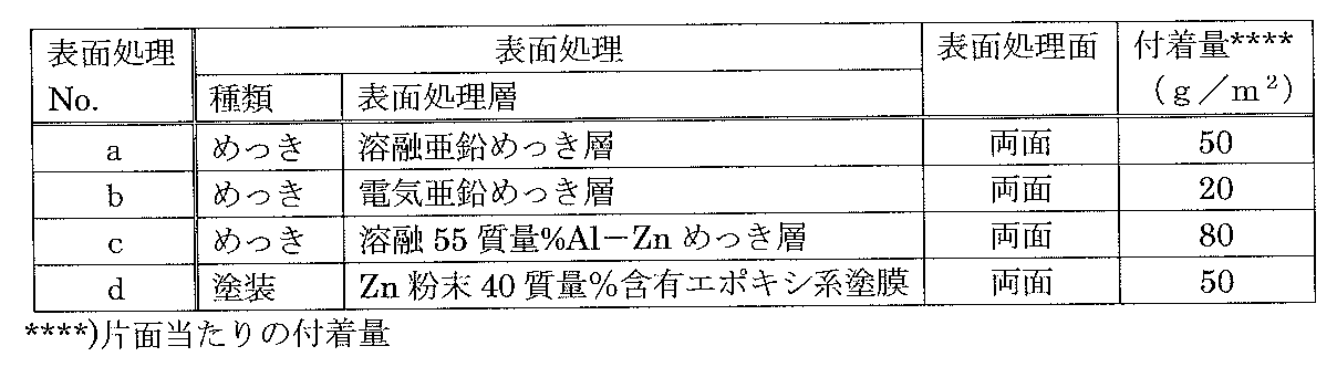
- Table 3 shows the surface treatment method.
- the surface treatment was changed according to the Si content of the steel sheet.
- a plating treatment was performed, and when the Si content of the steel sheet exceeded 0.5%, a coating treatment was performed.
- Steel plate No. 9 had a Si content exceeding 0.5%, but was plated. Although non-plating occurred, a corrosion test on the cut end face was performed.
- the obtained steel sheet after the surface treatment was sheared with a shearing machine, and a sample having a length of 50 mm and a width of 50 mm was collected from the central portion of the plate width.
- a wet and dry repeated test was performed.
- the test condition of the wet and dry test is that the sample is held at a temperature of 32 ° C and a relative humidity of 60% for 5 minutes on a wet testing machine, and then the sample is held at a temperature of 20 ° C and a relative humidity of 35% for 30 minutes.
- the treatment was set to 1 cycle, and the conditions were set to repeat 10 cycles.
- a steel plate having excellent corrosion resistance at the cut end face can be obtained. Therefore, when a steel sheet (surface-treated steel sheet) obtained by subjecting the steel sheet of the present invention to surface treatment such as plating treatment is actually applied to a strength member of home appliances, office equipment, etc., it exhibits excellent cut end surface corrosion resistance, Reusable.
Landscapes
- Chemical & Material Sciences (AREA)
- Engineering & Computer Science (AREA)
- Mechanical Engineering (AREA)
- Materials Engineering (AREA)
- Metallurgy (AREA)
- Organic Chemistry (AREA)
- Physics & Mathematics (AREA)
- Thermal Sciences (AREA)
- Crystallography & Structural Chemistry (AREA)
- Chemical Kinetics & Catalysis (AREA)
- Heat Treatment Of Sheet Steel (AREA)
- Coating With Molten Metal (AREA)
Abstract
Description
[1]質量%で、C:0.001%以上0.1%以下、Si:4.0%以下、Mn:0.16%以上1.0%以下、P:0.03%以下、S:0.02%以下、Al:0.003%以上0.06%以下を含有し、残部がFeおよび不可避的不純物からなる組成を有し、直径が0.5μm超えの析出物に含まれるMn量が100質量ppm以下である切断端面の耐食性に優れた鋼板。
[2]鋼板の片面または両面に、表面処理層として亜鉛系めっき層を備える鋼板であって、該鋼板が質量%で、C:0.001%以上0.1%以下、Si:0.5%以下、Mn:0.16%以上1.0%以下、P:0.03%以下、S:0.02%以下、Al:0.003%以上0.06%以下を含有し、残部がFeおよび不可避的不純物からなる組成を有し、直径が0.5μm超えの析出物に含まれるMn量が100質量ppm以下である切断端面の耐食性に優れた鋼板。
[3]前記[2]において、前記亜鉛系めっき層が、片面当たりのめっき付着量が5g/m2以上の亜鉛系めっき層である切断端面の耐食性に優れた鋼板。
[4]前記[3]において、前記亜鉛系めっき層の表面にさらに、無機被覆層、有機被覆層、無機有機複合被覆層のいずれか1種以上の被覆層を備える切断端面の耐食性に優れた鋼板。
[5]鋼板の片面または両面に、表面処理層として犠牲防食顔料を含む塗膜を有する鋼板であって、該鋼板が質量%で、C:0.001%以上0.1%以下、Si:0.5%超え4.0%以下、Mn:0.16%以上1.0%以下、P:0.03%以下、S:0.02%以下、Al:0.003%以上0.06%以下を含有し、残部がFeおよび不可避的不純物からなる組成を有し、直径が0.5μm超えの析出物に含まれるMn量が100質量ppm以下である切断端面の耐食性に優れた鋼板。
[6]前記[5]において、前記犠牲防食顔料を含む塗膜が、片面当たりの付着量で10g/m2以上の塗膜である切断端面の耐食性に優れた鋼板。
[7]前記[5]または[6]において、前記犠牲防食顔料が、Znおよび/またはAlを含む切断端面の耐食性に優れた鋼板。
[8]前記[5]ないし[7]のいずれかにおいて、前記塗膜の表面にさらに、無機被覆層、有機被覆層、無機有機複合被覆層のいずれか1種以上の被覆層を備える切断端面の耐食性に優れた鋼板。
[9]質量%で、C:0.001%以上0.1%以下、Si:4.0%以下、Mn:0.16%以上1.0%以下、P:0.03%以下、S :0.02%以下、Al:0.003%以上0.06%以下を含有し、残部がFeおよび不可避的不純物からなる組成を有する鋳片を、再加熱して1000℃以上1100℃以下の温度域に均熱保持した後、仕上げ圧延終了温度をAr3変態点以上とする熱間圧延を施し、680℃以下の巻取り温度で巻取ることにより熱延板とし、該熱延板を酸洗した後、60%以上90%以下の圧延率で冷間圧延を施して冷延板とし、該冷延板に、700℃以上850℃以下の焼鈍温度で連続焼鈍を施す切断端面の耐食性に優れた鋼板の製造方法。
[10]前記[9]において、前記連続焼鈍を施したのちに、表面処理を施し、鋼板の片面または両面に表面処理層を形成するに当たり、前記鋳片のSi含有量が質量%で0.5%以下である場合には、前記表面処理を亜鉛系めっき処理として前記表面処理層を亜鉛系めっき層とし、前記鋳片のSi含有量が質量%で0.5%超えである場合には、前記表面処理を犠牲防食顔料を含む塗料による塗装処理とし、前記表面処理層を犠牲防食顔料を含む塗膜とする切断端面の耐食性に優れた鋼板の製造方法。
[11]前記[10]において、前記亜鉛系めっき処理が、片面当たりのめっき付着量を5g/m2以上とするめっき処理であり、前記犠牲防食顔料を含む塗料による塗装処理が、片面当たりの付着量を10g/m2以上とする塗装処理である切断端面の耐食性に優れた鋼板の製造方法。
[12]前記[10]または[11]において、前記表面処理層の表面にさらに、無機被覆層、有機被覆層、無機有機複合被覆層のいずれか1種以上の被覆層を形成する切断端面の耐食性に優れた鋼板の製造方法。
C含有量が0.1%を超えると、鋼板の硬質化や延性の劣化が問題となる。一方、C含有量が0.001%未満になると、鋼板が軟化し過ぎて切断時にバリなどの不具合が発生し易くなる。したがって、C含有量は0.001%以上0.1%以下とする。好ましくは0.001%以上0.05%以下である。
Siは、固溶強化元素であり、鋼板の高強度化に寄与する。しかし、4.0%を超える多量の含有は、腐食起点となるSiO2に代表される析出物が増加して耐食性を著しく低下させる。このため、Si含有量は4.0%以下とする。下限は、不可避的不純物レベル(0.01%程度)とすることが望ましい。なお、めっき性の観点からは、0.5%以下に制限することが好ましく、より好ましくは耐食性の観点から0.1%以下、さらに好ましくは0.05%以下である。
Mnは、鋳片の熱間圧延時、Sによる赤熱脆性の抑制に有効な元素である。また、Mnは、固溶強化元素であり、鋼板の高強度化に有効な元素である。引張強さ(TS)440MPa超えの鋼板強度を得るためには、Mn含有量を0.16%以上とする必要がある。一方、Mn含有量が1.0%を超えると、鋼の連続鋳造中にMnSが析出して熱間脆性を促進し、鋳片割れを招く。また、Mn含有量が1.0%を超えると、鋼板の耐食性が劣化する。したがって、Mn含有量は0.16%以上1.0%以下とする。好ましくは0.16%以上0.5%以下である。
Pは、不可避的に含有される元素であり、その含有量が増加するにつれて鋼板の耐食性が劣化する。したがって、P含有量は0.03%以下とする。
Sは、不可避的に含有される元素であり、鋳片の熱間圧延時に赤熱脆性を招く有害な元素である。また、Sは、鋼の連続鋳造中にMnSとして析出して熱間脆性を促進し、鋳片割れを招く。したがって、S含有量は、極力低減することが好ましく、0.02%以下とする。好ましくは0.01%以下である。
Alは、製鋼の脱酸に必要な元素であり、その含有量を0.003%以上とする。一方、Al含有量が過剰に高くなると、介在物が増加して鋼板の表面欠陥が発生し易くなる。したがって、Al含有量は0.06%以下とする。
先述のとおり、鋼板中に存在する析出物のうち、直径が0.5μm超えの析出物に含まれるMn量が100質量ppmを超えると、鋼板の耐食性が著しく低下する。したがって、直径が0.5μm超えの析出物に含まれるMn量を100質量ppm以下とする。好ましくは90質量ppm以下である。なお、本発明の鋼板に存在する析出物のうち、Mnを含有する析出物は主に(Mn・Fe)Sなる組成を有するが、MnSが多少混在する場合もある。
本発明においては、再加熱温度を、鋳片に存在する析出物(主に(Mn・Fe)S)が溶解しない温度域に設定する。鋳片の再加熱温度が1100℃超えると、鋳片中の析出物が溶解してしまう。その結果、後工程の連続焼鈍時に、MnSが析出してしまい、鋼板の耐食性が劣化する。一方、鋳片の再加熱温度が1000℃を下回ると、圧延性が著しく低下し、熱間圧延に支障をきたす。したがって、鋳片の再加熱温度は1000℃以上1100℃以下とする。
仕上げ圧延終了温度がAr3変態点未満になると、圧延後の結晶粒径が不均一になり易くなる。鋼板の結晶粒径が不均一になると、鋼板を所定形状の部材にプレス成形する際、不均一変形やプレス表面の肌荒れ等の問題が生じる。したがって、仕上げ圧延終了温度はAr3変態点以上とする。好ましくは、Ar3変態点+5℃以上である。但し、仕上げ圧延終了温度が過剰に高くなると、スケールによる表面性状の劣化や生産能率の低下が懸念されるため、Ar3変態点+50℃以下とすることが好ましい。
巻取り温度が680℃を超えると、鋳片に存在していた析出物(主に(Mn・Fe)S)の溶解が促進される。その結果、後工程の連続焼鈍時にMnSが析出し、鋼板の耐食性が劣化する。したがって、巻取り温度は680℃以下とする。但し、巻取り温度が低くなり過ぎると、生産性の低下が懸念されるため、650℃以上とすることが好ましい。
冷間圧延の圧延率が60%を下回ると、後工程の連続焼鈍で結晶粒径が粗大となり、鋼板のプレス成形時に表面外観が劣化する。一方、冷間圧延の圧延率が90%を超えると、圧延負荷が大きくなるため、圧延が困難になる。したがって、冷間圧延の圧延率は60%以上90%以下とする。好ましくは70%以上90%以下である。
本発明では、鋼の再結晶温度以上の温度域で連続焼鈍を施し、加工組織を再結晶化させることで鋼板の加工性向上を図る。焼鈍温度が700℃未満になると、鋼の再結晶を促進することができない。その結果、鋼板に硬質な加工組織が残留してプレス成形性が劣化する。一方、焼鈍温度が850℃を超えると、エネルギー負荷が大きくなり、生産コストの高騰を招く。したがって、連続焼鈍の焼鈍温度は700℃以上850℃以下とする。好ましくは720℃以上830℃以下である。


Claims (12)
- 質量%で、C:0.001%以上0.1%以下、Si:4.0%以下、Mn:0.16%以上1.0%以下、P:0.03%以下、S :0.02%以下、Al:0.003%以上0.06%以下を含有し、残部がFeおよび不可避的不純物からなる組成を有し、
直径が0.5μm超えの析出物に含まれるMn量が100質量ppm以下である切断端面の耐食性に優れた鋼板。 - 鋼板の片面または両面に、表面処理層として亜鉛系めっき層を備える鋼板であって、
該鋼板が質量%で、C:0.001%以上0.1%以下、Si:0.5%以下、Mn:0.16%以上1.0%以下、P:0.03%以下、S :0.02%以下、Al:0.003%以上0.06%以下を含有し、残部がFeおよび不可避的不純物からなる組成を有し、
直径が0.5μm超えの析出物に含まれるMn量が100質量ppm以下である切断端面の耐食性に優れた鋼板。 - 前記亜鉛系めっき層が、片面当たりのめっき付着量が5g/m2以上の亜鉛系めっき層である請求項2に記載の切断端面の耐食性に優れた鋼板。
- 前記亜鉛系めっき層の表面にさらに、無機被覆層、有機被覆層、無機有機複合被覆層のいずれか1種以上の被覆層を備える請求項3に記載の切断端面の耐食性に優れた鋼板。
- 鋼板の片面または両面に、表面処理層として犠牲防食顔料を含む塗膜を有する鋼板であって、該鋼板が質量%で、C :0.001%以上0.1%以下、Si:0.5%超え4.0%以下、Mn:0.16%以上1.0%以下、P:0.03%以下、S:0.02%以下、Al:0.003%以上0.06%以下を含有し、残部がFeおよび不可避的不純物からなる組成を有し、
直径が0.5μm超えの析出物に含まれるMn量が100質量ppm以下である切断端面の耐食性に優れた鋼板。 - 前記犠牲防食顔料を含む塗膜が、片面当たりの付着量で10g/m2以上の塗膜である請求項5に記載の切断端面の耐食性に優れた鋼板。
- 前記犠牲防食顔料が、Znおよび/またはAlを含む請求項5または6に記載の切断端面の耐食性に優れた鋼板。
- 前記犠牲防食顔料を含む塗膜の表面にさらに、無機被覆層、有機被覆層、無機有機複合被覆層のいずれか1種以上の被覆層を備える請求項5ないし7のいずれか一項に記載の切断端面の耐食性に優れた鋼板。
- 質量%で、C:0.001%以上0.1%以下、Si:4.0%以下、Mn:0.16%以上1.0%以下、P:0.03%以下、S:0.02%以下、Al:0.003%以上0.06%以下を含有し、残部がFeおよび不可避的不純物からなる組成を有する鋳片を、再加熱して1000℃以上1100℃以下の温度域に均熱保持した後、仕上げ圧延終了温度をAr3変態点以上とする熱間圧延を施し、680℃以下の巻取り温度で巻取ることにより熱延板とし、該熱延板を酸洗した後、60%以上90%以下の圧延率で冷間圧延を施して冷延板とし、該冷延板に、700℃以上850℃以下の焼鈍温度で連続焼鈍を施す切断端面の耐食性に優れた鋼板の製造方法。
- 前記連続焼鈍を施したのちに、表面処理を施し、鋼板の片面または両面に表面処理層を形成するにあたり、前記鋳片のSi含有量が質量%で0.5%以下である場合には、前記表面処理を亜鉛系めっき処理として前記表面処理層を亜鉛系めっき層とし、
前記鋳片のSi含有量が質量%で0.5%超えである場合には、前記表面処理を犠牲防食顔料を含む塗料による塗装とし、前記表面処理層を犠牲防食顔料を含む塗膜とする、
請求項9に記載の切断端面の耐食性に優れた鋼板の製造方法。 - 前記亜鉛めっき処理が、片面当たりのめっき付着量を5g/m2以上とするめっき処理であり、
前記犠牲防食顔料を含む塗装処理が、片面当たりの付着量を10g/m2以上とする塗装処理である、
請求項10に記載の切断端面の耐食性に優れた鋼板の製造方法。 - 前記表面処理層の表面にさらに、無機被覆層、有機被覆層、無機有機複合被覆層のいずれか1種以上の被覆層を形成する請求項10または11に記載の切断端面の耐食性に優れた鋼板の製造方法。
Priority Applications (2)
| Application Number | Priority Date | Filing Date | Title |
|---|---|---|---|
| CN201480043485.0A CN105452508B (zh) | 2013-07-31 | 2014-07-16 | 切割端面的耐腐蚀性优良的钢板及其制造方法 |
| KR1020157033582A KR101771337B1 (ko) | 2013-07-31 | 2014-07-16 | 절단 단면의 내식성이 우수한 강판 및 그 제조 방법 |
Applications Claiming Priority (2)
| Application Number | Priority Date | Filing Date | Title |
|---|---|---|---|
| JP2013158468 | 2013-07-31 | ||
| JP2013-158468 | 2013-07-31 |
Publications (1)
| Publication Number | Publication Date |
|---|---|
| WO2015015740A1 true WO2015015740A1 (ja) | 2015-02-05 |
Family
ID=52431303
Family Applications (1)
| Application Number | Title | Priority Date | Filing Date |
|---|---|---|---|
| PCT/JP2014/003776 Ceased WO2015015740A1 (ja) | 2013-07-31 | 2014-07-16 | 切断端面の耐食性に優れた鋼板およびその製造方法 |
Country Status (4)
| Country | Link |
|---|---|
| JP (1) | JP6065884B2 (ja) |
| KR (1) | KR101771337B1 (ja) |
| CN (1) | CN105452508B (ja) |
| WO (1) | WO2015015740A1 (ja) |
Families Citing this family (5)
| Publication number | Priority date | Publication date | Assignee | Title |
|---|---|---|---|---|
| JP6972722B2 (ja) * | 2017-07-18 | 2021-11-24 | 日本製鉄株式会社 | 低合金鋼 |
| CN109425319B (zh) * | 2017-08-25 | 2020-06-23 | 宝山钢铁股份有限公司 | 一种检测酸洗过程对横向断面影响程度的方法 |
| DE112018007004T5 (de) * | 2018-02-01 | 2020-10-29 | Sumitomo Electric Industries, Ltd. | Kupferbeschichteter Stahldraht und geneigte Spiralfeder |
| KR102490927B1 (ko) * | 2020-12-21 | 2023-01-26 | 주식회사 포스코 | 외장패널용 도금 강판 및 그 제조 방법 |
| CN115445892A (zh) * | 2022-10-21 | 2022-12-09 | 乔冠应用材料(淮安)有限公司 | 一种铜材料带卷裁切面防腐处理工艺 |
Citations (3)
| Publication number | Priority date | Publication date | Assignee | Title |
|---|---|---|---|---|
| JP2005187837A (ja) * | 2003-12-24 | 2005-07-14 | Nippon Steel Corp | プレス成型性、耐食性および二次加工性に優れた自動車燃料タンク用高強度鋼板およびその製造方法 |
| JP2010126764A (ja) * | 2008-11-27 | 2010-06-10 | Kobe Steel Ltd | 切断端面耐食性に優れたクロメートフリー化成処理亜鉛めっき鋼板 |
| JP2011117040A (ja) * | 2009-12-03 | 2011-06-16 | Sumitomo Metal Ind Ltd | 合金化溶融亜鉛めっき鋼板およびその製造方法 |
Family Cites Families (8)
| Publication number | Priority date | Publication date | Assignee | Title |
|---|---|---|---|---|
| JPH10330883A (ja) * | 1997-04-03 | 1998-12-15 | Kawasaki Steel Corp | 耐端面錆性に優れる表面処理鋼板 |
| JP3319385B2 (ja) * | 1998-04-20 | 2002-08-26 | 日本鋼管株式会社 | 加工性、耐傷つき性及び耐食性に優れた塗装亜鉛めっき鋼板及びその製造方法 |
| JP4311019B2 (ja) | 2003-01-10 | 2009-08-12 | Jfeスチール株式会社 | 切断端面の耐食性に優れた表面処理鋼板 |
| JP5549307B2 (ja) * | 2009-04-13 | 2014-07-16 | Jfeスチール株式会社 | 時効性および焼付け硬化性に優れた冷延鋼板およびその製造方法 |
| JP5477002B2 (ja) * | 2010-01-13 | 2014-04-23 | 新日鐵住金株式会社 | 冷延鋼板 |
| JP5397263B2 (ja) | 2010-02-23 | 2014-01-22 | Jfeスチール株式会社 | 高張力冷延鋼板およびその製造方法 |
| JP5196074B2 (ja) * | 2010-05-31 | 2013-05-15 | 新日鐵住金株式会社 | 切断端面耐食性及び加工部耐食性に優れた溶融アルミニウム合金めっき鋼材とその製造方法 |
| CN103074546B (zh) * | 2011-10-25 | 2014-12-10 | 上海梅山钢铁股份有限公司 | 冰箱冷凝管用冷轧带钢的制造方法 |
-
2014
- 2014-07-15 JP JP2014144714A patent/JP6065884B2/ja active Active
- 2014-07-16 KR KR1020157033582A patent/KR101771337B1/ko active Active
- 2014-07-16 WO PCT/JP2014/003776 patent/WO2015015740A1/ja not_active Ceased
- 2014-07-16 CN CN201480043485.0A patent/CN105452508B/zh active Active
Patent Citations (3)
| Publication number | Priority date | Publication date | Assignee | Title |
|---|---|---|---|---|
| JP2005187837A (ja) * | 2003-12-24 | 2005-07-14 | Nippon Steel Corp | プレス成型性、耐食性および二次加工性に優れた自動車燃料タンク用高強度鋼板およびその製造方法 |
| JP2010126764A (ja) * | 2008-11-27 | 2010-06-10 | Kobe Steel Ltd | 切断端面耐食性に優れたクロメートフリー化成処理亜鉛めっき鋼板 |
| JP2011117040A (ja) * | 2009-12-03 | 2011-06-16 | Sumitomo Metal Ind Ltd | 合金化溶融亜鉛めっき鋼板およびその製造方法 |
Also Published As
| Publication number | Publication date |
|---|---|
| CN105452508B (zh) | 2018-10-09 |
| CN105452508A (zh) | 2016-03-30 |
| KR20160003098A (ko) | 2016-01-08 |
| KR101771337B1 (ko) | 2017-08-24 |
| JP2015045086A (ja) | 2015-03-12 |
| JP6065884B2 (ja) | 2017-01-25 |
Similar Documents
| Publication | Publication Date | Title |
|---|---|---|
| KR101368990B1 (ko) | 내식성이 우수한 용융 Zn-Al-Mg-Si-Cr 합금 도금 강재 | |
| CN105531385B (zh) | 制造设有金属防腐蚀保护层的钢构件的方法以及钢构件 | |
| JP5650222B2 (ja) | 腐食に対する保護を与える金属コーティングが施された鋼部材を製造する方法、および鋼部材 | |
| JP2022095822A (ja) | 溶接性及び加工部耐食性に優れた亜鉛合金めっき鋼材及びその製造方法 | |
| JPWO2019221193A1 (ja) | めっき鋼材 | |
| US10676804B2 (en) | Steel sheet provided with a coating providing sacrificial cathodic protection comprising lanthane | |
| KR101668638B1 (ko) | 합금화 용융 아연 도금 강판 | |
| JP6065884B2 (ja) | 切断端面の耐食性に優れた鋼板およびその製造方法 | |
| JPWO2014155944A1 (ja) | 溶融Al−Zn系めっき鋼板及びその製造方法 | |
| KR20180095698A (ko) | 고항복비형 고강도 아연 도금 강판 및 그의 제조 방법 | |
| JP3598087B2 (ja) | 加工性の優れた高強度合金化溶融亜鉛めっき鋼板およびその製造方法 | |
| JP2011231377A (ja) | 高強度鋼板 | |
| CN104364410B (zh) | 高强度钢板和高强度热镀锌钢板以及它们的制造方法 | |
| WO2021215100A1 (ja) | 溶融亜鉛めっき鋼板及びその製造方法 | |
| JPH05255799A (ja) | 加工性に優れた溶融めっき熱延高強度鋼板およびその製造方法 | |
| JP5625442B2 (ja) | 耐遅れ破壊性に優れた引張強度1180MPa以上を有する高強度鋼板 | |
| KR101736640B1 (ko) | 도금성 및 점용접성이 우수한 아연계 도금강판 및 그 제조방법 | |
| JP4940813B2 (ja) | TS×Elの値が21000MPa・%以上である溶融亜鉛めっき鋼板の製造方法 | |
| JP2004277839A (ja) | 亜鉛系金属被覆鋼材 | |
| JP4655366B2 (ja) | めっき密着性及び耐食性に優れた高強度合金化溶融亜鉛めっき鋼板及びその製造方法 | |
| JP2016060945A (ja) | 溶融Al系めっき鋼板 | |
| JP5907106B2 (ja) | 亜鉛めっき冷延鋼板 | |
| JP4846550B2 (ja) | 合金化溶融亜鉛めっき用鋼板及び合金化溶融亜鉛めっき鋼板 | |
| JP3294322B2 (ja) | 塗装焼付硬化性および耐食性に優れた深絞り用溶融亜鉛めっき鋼板の製造方法 | |
| JP6337711B2 (ja) | 溶融Al系めっき鋼板 |
Legal Events
| Date | Code | Title | Description |
|---|---|---|---|
| WWE | Wipo information: entry into national phase |
Ref document number: 201480043485.0 Country of ref document: CN |
|
| 121 | Ep: the epo has been informed by wipo that ep was designated in this application |
Ref document number: 14831991 Country of ref document: EP Kind code of ref document: A1 |
|
| ENP | Entry into the national phase |
Ref document number: 20157033582 Country of ref document: KR Kind code of ref document: A |
|
| WWE | Wipo information: entry into national phase |
Ref document number: IDP00201508246 Country of ref document: ID |
|
| NENP | Non-entry into the national phase |
Ref country code: DE |
|
| 122 | Ep: pct application non-entry in european phase |
Ref document number: 14831991 Country of ref document: EP Kind code of ref document: A1 |