WO2015015599A1 - 低振動形フローティングメタルベアリング - Google Patents
低振動形フローティングメタルベアリング Download PDFInfo
- Publication number
- WO2015015599A1 WO2015015599A1 PCT/JP2013/070764 JP2013070764W WO2015015599A1 WO 2015015599 A1 WO2015015599 A1 WO 2015015599A1 JP 2013070764 W JP2013070764 W JP 2013070764W WO 2015015599 A1 WO2015015599 A1 WO 2015015599A1
- Authority
- WO
- WIPO (PCT)
- Prior art keywords
- bearing
- floating metal
- vibration
- metal bearing
- roundness
- Prior art date
Links
Images


Classifications
-
- F—MECHANICAL ENGINEERING; LIGHTING; HEATING; WEAPONS; BLASTING
- F16—ENGINEERING ELEMENTS AND UNITS; GENERAL MEASURES FOR PRODUCING AND MAINTAINING EFFECTIVE FUNCTIONING OF MACHINES OR INSTALLATIONS; THERMAL INSULATION IN GENERAL
- F16C—SHAFTS; FLEXIBLE SHAFTS; ELEMENTS OR CRANKSHAFT MECHANISMS; ROTARY BODIES OTHER THAN GEARING ELEMENTS; BEARINGS
- F16C32/00—Bearings not otherwise provided for
- F16C32/06—Bearings not otherwise provided for with moving member supported by a fluid cushion formed, at least to a large extent, otherwise than by movement of the shaft, e.g. hydrostatic air-cushion bearings
- F16C32/0629—Bearings not otherwise provided for with moving member supported by a fluid cushion formed, at least to a large extent, otherwise than by movement of the shaft, e.g. hydrostatic air-cushion bearings supported by a liquid cushion, e.g. oil cushion
- F16C32/064—Bearings not otherwise provided for with moving member supported by a fluid cushion formed, at least to a large extent, otherwise than by movement of the shaft, e.g. hydrostatic air-cushion bearings supported by a liquid cushion, e.g. oil cushion the liquid being supplied under pressure
- F16C32/0651—Details of the bearing area per se
- F16C32/0655—Details of the bearing area per se of supply openings
-
- F—MECHANICAL ENGINEERING; LIGHTING; HEATING; WEAPONS; BLASTING
- F16—ENGINEERING ELEMENTS AND UNITS; GENERAL MEASURES FOR PRODUCING AND MAINTAINING EFFECTIVE FUNCTIONING OF MACHINES OR INSTALLATIONS; THERMAL INSULATION IN GENERAL
- F16C—SHAFTS; FLEXIBLE SHAFTS; ELEMENTS OR CRANKSHAFT MECHANISMS; ROTARY BODIES OTHER THAN GEARING ELEMENTS; BEARINGS
- F16C17/00—Sliding-contact bearings for exclusively rotary movement
- F16C17/02—Sliding-contact bearings for exclusively rotary movement for radial load only
- F16C17/028—Sliding-contact bearings for exclusively rotary movement for radial load only with fixed wedges to generate hydrodynamic pressure, e.g. multi-lobe bearings
-
- F—MECHANICAL ENGINEERING; LIGHTING; HEATING; WEAPONS; BLASTING
- F16—ENGINEERING ELEMENTS AND UNITS; GENERAL MEASURES FOR PRODUCING AND MAINTAINING EFFECTIVE FUNCTIONING OF MACHINES OR INSTALLATIONS; THERMAL INSULATION IN GENERAL
- F16C—SHAFTS; FLEXIBLE SHAFTS; ELEMENTS OR CRANKSHAFT MECHANISMS; ROTARY BODIES OTHER THAN GEARING ELEMENTS; BEARINGS
- F16C17/00—Sliding-contact bearings for exclusively rotary movement
- F16C17/12—Sliding-contact bearings for exclusively rotary movement characterised by features not related to the direction of the load
- F16C17/18—Sliding-contact bearings for exclusively rotary movement characterised by features not related to the direction of the load with floating brasses or brushing, rotatable at a reduced speed
-
- F—MECHANICAL ENGINEERING; LIGHTING; HEATING; WEAPONS; BLASTING
- F16—ENGINEERING ELEMENTS AND UNITS; GENERAL MEASURES FOR PRODUCING AND MAINTAINING EFFECTIVE FUNCTIONING OF MACHINES OR INSTALLATIONS; THERMAL INSULATION IN GENERAL
- F16C—SHAFTS; FLEXIBLE SHAFTS; ELEMENTS OR CRANKSHAFT MECHANISMS; ROTARY BODIES OTHER THAN GEARING ELEMENTS; BEARINGS
- F16C32/00—Bearings not otherwise provided for
- F16C32/06—Bearings not otherwise provided for with moving member supported by a fluid cushion formed, at least to a large extent, otherwise than by movement of the shaft, e.g. hydrostatic air-cushion bearings
- F16C32/0629—Bearings not otherwise provided for with moving member supported by a fluid cushion formed, at least to a large extent, otherwise than by movement of the shaft, e.g. hydrostatic air-cushion bearings supported by a liquid cushion, e.g. oil cushion
- F16C32/064—Bearings not otherwise provided for with moving member supported by a fluid cushion formed, at least to a large extent, otherwise than by movement of the shaft, e.g. hydrostatic air-cushion bearings supported by a liquid cushion, e.g. oil cushion the liquid being supplied under pressure
- F16C32/0651—Details of the bearing area per se
-
- F—MECHANICAL ENGINEERING; LIGHTING; HEATING; WEAPONS; BLASTING
- F16—ENGINEERING ELEMENTS AND UNITS; GENERAL MEASURES FOR PRODUCING AND MAINTAINING EFFECTIVE FUNCTIONING OF MACHINES OR INSTALLATIONS; THERMAL INSULATION IN GENERAL
- F16C—SHAFTS; FLEXIBLE SHAFTS; ELEMENTS OR CRANKSHAFT MECHANISMS; ROTARY BODIES OTHER THAN GEARING ELEMENTS; BEARINGS
- F16C33/00—Parts of bearings; Special methods for making bearings or parts thereof
- F16C33/02—Parts of sliding-contact bearings
- F16C33/04—Brasses; Bushes; Linings
- F16C33/06—Sliding surface mainly made of metal
- F16C33/10—Construction relative to lubrication
- F16C33/1025—Construction relative to lubrication with liquid, e.g. oil, as lubricant
- F16C33/1045—Details of supply of the liquid to the bearing
-
- F—MECHANICAL ENGINEERING; LIGHTING; HEATING; WEAPONS; BLASTING
- F16—ENGINEERING ELEMENTS AND UNITS; GENERAL MEASURES FOR PRODUCING AND MAINTAINING EFFECTIVE FUNCTIONING OF MACHINES OR INSTALLATIONS; THERMAL INSULATION IN GENERAL
- F16C—SHAFTS; FLEXIBLE SHAFTS; ELEMENTS OR CRANKSHAFT MECHANISMS; ROTARY BODIES OTHER THAN GEARING ELEMENTS; BEARINGS
- F16C33/00—Parts of bearings; Special methods for making bearings or parts thereof
- F16C33/02—Parts of sliding-contact bearings
- F16C33/04—Brasses; Bushes; Linings
- F16C33/06—Sliding surface mainly made of metal
- F16C33/10—Construction relative to lubrication
- F16C33/1025—Construction relative to lubrication with liquid, e.g. oil, as lubricant
- F16C33/106—Details of distribution or circulation inside the bearings, e.g. details of the bearing surfaces to affect flow or pressure of the liquid
- F16C33/1075—Wedges, e.g. ramps or lobes, for generating pressure
-
- F—MECHANICAL ENGINEERING; LIGHTING; HEATING; WEAPONS; BLASTING
- F16—ENGINEERING ELEMENTS AND UNITS; GENERAL MEASURES FOR PRODUCING AND MAINTAINING EFFECTIVE FUNCTIONING OF MACHINES OR INSTALLATIONS; THERMAL INSULATION IN GENERAL
- F16C—SHAFTS; FLEXIBLE SHAFTS; ELEMENTS OR CRANKSHAFT MECHANISMS; ROTARY BODIES OTHER THAN GEARING ELEMENTS; BEARINGS
- F16C33/00—Parts of bearings; Special methods for making bearings or parts thereof
- F16C33/02—Parts of sliding-contact bearings
- F16C33/04—Brasses; Bushes; Linings
- F16C33/06—Sliding surface mainly made of metal
- F16C33/10—Construction relative to lubrication
- F16C33/1025—Construction relative to lubrication with liquid, e.g. oil, as lubricant
- F16C33/106—Details of distribution or circulation inside the bearings, e.g. details of the bearing surfaces to affect flow or pressure of the liquid
- F16C33/1085—Channels or passages to recirculate the liquid in the bearing
-
- F—MECHANICAL ENGINEERING; LIGHTING; HEATING; WEAPONS; BLASTING
- F16—ENGINEERING ELEMENTS AND UNITS; GENERAL MEASURES FOR PRODUCING AND MAINTAINING EFFECTIVE FUNCTIONING OF MACHINES OR INSTALLATIONS; THERMAL INSULATION IN GENERAL
- F16C—SHAFTS; FLEXIBLE SHAFTS; ELEMENTS OR CRANKSHAFT MECHANISMS; ROTARY BODIES OTHER THAN GEARING ELEMENTS; BEARINGS
- F16C33/00—Parts of bearings; Special methods for making bearings or parts thereof
- F16C33/02—Parts of sliding-contact bearings
- F16C33/04—Brasses; Bushes; Linings
- F16C33/06—Sliding surface mainly made of metal
- F16C33/14—Special methods of manufacture; Running-in
-
- F—MECHANICAL ENGINEERING; LIGHTING; HEATING; WEAPONS; BLASTING
- F16—ENGINEERING ELEMENTS AND UNITS; GENERAL MEASURES FOR PRODUCING AND MAINTAINING EFFECTIVE FUNCTIONING OF MACHINES OR INSTALLATIONS; THERMAL INSULATION IN GENERAL
- F16C—SHAFTS; FLEXIBLE SHAFTS; ELEMENTS OR CRANKSHAFT MECHANISMS; ROTARY BODIES OTHER THAN GEARING ELEMENTS; BEARINGS
- F16C2360/00—Engines or pumps
- F16C2360/23—Gas turbine engines
- F16C2360/24—Turbochargers
Definitions
- the present invention relates to a bearing technology. More specifically, the present invention relates to a bearing bearing surface in a sliding bearing.
- the present invention relates to a low-vibration floating metal bearing technology that exhibits a high centering effect up to the rotation region and that can prevent noise from being generated due to the vibration-suppressing effect.
- bearings play a major role and are important factors that determine the performance and accuracy of products.
- a bearing that supports high-speed rotation at high temperatures and high loads must maintain a certain level of performance even under severe conditions.
- bearings are roughly divided, they are divided into sliding bearings and rolling bearings, and the one that suits the usage conditions and purpose is selected, but depending on the product, both may be used properly even in the same part of the same product. .
- a floating metal bearing and a ball bearing are properly used for a bearing of a turbine shaft of an exhaust turbocharger used in an internal combustion engine of an automobile.
- ball bearings have many advantages in terms of performance, such as friction, the ball bearing turbine requires a lot of oil, and an orifice is installed in the banjo bolt of the oil line to reduce the amount of oil. Failure to do so will cause problems due to excessive oil volume.
- some turbines have a rotational speed exceeding 200,000 rpm and receive high-temperature exhaust gas (800-900 °C) directly, so oil is more likely to deteriorate than natural intake, which is more severe than oil-controlled ball bearings.
- floating metal bearings are more economical in terms of manufacturing costs and running costs.
- the exhaust turbine type turbocharger can greatly improve the output even with a small displacement, especially because it is compatible with a diesel engine, so recently, an eco-car that combines a gasoline engine and a turbocharger with a small displacement, Clean diesel, which combines a diesel engine with reduced exhaust gas and a turbocharger, has begun to attract attention as well as hybrid and EV.
- floating metal bearings which have few problems such as cost and oil management, will improve performance characteristics such as friction characteristics and durability similar to ball bearings from the social situation such as environment and resources. This is where it is desired.
- the sliding bearing still has a big problem that noise such as noise is easily generated with respect to the ball bearing. The problem of removing noise and the like from a material that slides at high speed cannot be solved overnight.
- significant improvements have been made in the technical field of floating bearings due to the development of floating technology, but it is still not sufficient.
- Patent Document 1 and Patent Document 2 are both in common with the purpose of reducing the noise of the present invention in order to suppress the generation of noise.
- the centering effect of the metal by the dynamic pressure is that the dynamic pressure is Since it acts on the entire circumference of the floating metal bearing, the centering effect is weak compared to the present invention. This is because even if rotation starts from the time when the shaft is stopped, the cross-sectional area of the flow-in channel is small, so that a large flow velocity difference does not occur.
- turbocharger bearing structure has a large number of parts such as a thrust bearing, a radial bearing, a plurality of bushes, and further an air pressurizing mechanism. It can be said that the cost is severe. In addition, there is no suggestion or description about the configuration for removing noise.
- the inventors of the present application have been reviewing various processing conditions such as surface roughness and roundness, and even if high-precision roundness characteristics and surface roughness characteristics are improved, noise generation, that is, Due to the fact that it was difficult to suppress the occurrence of vibration that caused the noise, it is not possible to suppress the occurrence of vibration by changing the roundness of the inner surface of the bearing hole in a polygonal manner. Based on this idea, the present invention was completed as a result of repeated experiments with various roundness changes.
- the present invention provides a sliding bearing in which a narrow flow path and a wide flow path are gently connected by changing the clearance amount between the surface of the bearing hole with different fluid lubrication conditions (the clearance amount between the shaft surface and the inner surface of the bearing hole).
- the present invention adopts means characterized in that it is the low vibration type floating metal bearing described in the above, characterized in that the number of oil supply holes drilled in the equiangular direction is six. You can also
- the low-vibration type floating metal bearing According to the low-vibration type floating metal bearing according to the present invention, a plurality of regions having different fluid lubrication conditions from the shaft center to an isometric isotropic position (by changing the clearance amount between the shaft surface and the inner surface of the bearing hole, High centering effect from low rotation range to high rotation range by applying inner surface processing that equidistantly and isotropically connects multiple narrow flow channels and wide flow channels) In order to make it difficult for improper vibrations and self-excited vibrations to occur, it is possible to suppress the generation of noise caused by these.
- the low vibration type floating metal bearing according to the present invention although it is a sliding bearing, it exhibits excellent performance functions such as friction characteristics and durability similar to a ball bearing, and at the same time, it is necessary for a ball bearing or the like. There is no need for hydraulic control and management and other special parts.
- the centering effect exerts an effect of suppressing the swinging by the dynamic pressure acting so as to always go to the axial center as soon as the rotation starts.
- rotational resistance is reduced when compared with conventional floating bearings composed of conventional circular shapes.
- the greatest feature of the present invention is that surface processing is repeated between a narrow channel and a wide channel by changing the clearance between the shaft surface and the inner surface of the bearing hole 40.
- the narrowest part of the clearance is hereinafter referred to as “narrowest part”, and the widest part is hereinafter referred to as “widest part”.
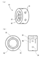
- FIG. 1 is an explanatory view for explaining the outline of a low vibration type floating metal 10 according to the present invention
- FIG. 1A is a perspective view
- FIG. 1B is a plan view and a side view of one cross section.
- FIG. 1 at first glance, it looks like a normal floating metal.
- a plurality of oil supply holes 30 are provided equiangularly.
- it is also effective to provide an oil supply groove and provide the oil hole “30 in the oil supply groove.
- FIG. 1 shows six oil supplies.
- the hole 30 is shown, it is not limited to this number, and is not particularly limited as long as the effect produced from the inner surface shape of the bearing hole 40 to be said to be the main part of the present invention is exhibited. Further, it is not affected by the cross-sectional area of the oil supply hole 30 or other factors.
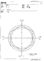
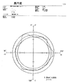
- FIG. 2 to 6 show the results of measuring the roundness of the inner surface of the bearing hole 40 according to the present invention.
- FIG. 2 shows the measurement of the roundness at the center of the outer peripheral edge. Specifically, FIG. 2 shows the result of measuring the position of 4.13 mm inward from one end face.
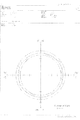
- FIG. 3 shows the measurement in the vicinity of the end surface, and specifically, the measurement is made at a position entering 0.88 mm inside from one end surface. Note that the roundness of the opposite end face is the same as that shown in FIG. In all of FIGS. 2 to 6, the measurement magnification is 2000 times.
- the lines drawn in Fig. 2 and Fig. 6 are JIS B7451, as shown in JIS B7451, the innermost circle has the maximum height and the outermost circle has the maximum depth. The average value of degrees is shown. The roundness up to the maximum height and depth was 4.87 ⁇ m in FIG. 2 and 3.83 ⁇ m near the end face shown in FIG.
- the metal bearing used for the experiment data is one provided with six oil supply holes 30. However, what is not specified is as described above.
- Figure 4 shows the pursuit of roundness, and the roundness is 1.28 ⁇ m. It can be seen that the roundness is clearly higher than other figures. However, the vibration meter measurement showed no particular tendency to attenuate vibration.
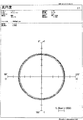
- Fig. 5 is intentionally prepared to know the state where the roundness is disturbed, and it is a defective product level that does not reach the quality standard for ensuring quality in normal products. However, it can be seen that there is little influence on problems such as vibration and noise.
- FIG. 6 shows the roundness when the dynamic pressure generation point is provided with an opening of 120 degrees so as to form a triangular shape which is the largest division for equiangular isometric division. In such a case as well, the occurrence of vibration is suppressed as described above.
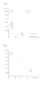
- FIG. 7 is an explanatory diagram showing a basic idea for vibration reduction.
- FIG. 7A shows the frequency (G) on the vertical axis and the arithmetic average roughness (Ra) on the horizontal axis.
- the fact that the round mark at the top of the graph changes horizontally indicates that even if the surface roughness is improved, the vibration that causes noise is not affected.
- the left surface is Ra0.06, and the right surface is near Ra0.4.
- the vibration decreases as the change in the vertical axis on the left side of the graph, that is, the increase / decrease of the vibration becomes more polygonal than the circle shape having a high roundness of the circle shape.
- FIG. 7A shows the frequency (G) on the vertical axis and the arithmetic average roughness (Ra) on the horizontal axis.
- the fact that the round mark at the top of the graph changes horizontally indicates that even if the surface roughness is improved, the vibration that causes noise is not affected.
- the left surface is Ra0.06, and
- the upper left corner has a roundness of 0.8 ⁇ m or less, and the lower right corner has a roundness of 2.5 to 4 ⁇ m.
- FIG. 8 is a graph using a general Stribeck curve for explaining the lubrication state of the low vibration type floating metal bearing 10 according to the present invention.
- the graph line drawn with a solid line in FIG. 8 is a Stribeck curve that is commonly used to explain the lubrication state between two surfaces that perform relative motion, and is drawn with a one-dot chain line. It is a virtual curve based on the experimental result of the lubrication state of the low vibration type floating metal bearing 10 according to the present invention. Since the low-vibration type floating metal bearing 10 according to the present invention can reduce the vibration, the fluid friction due to the vibration can be reduced. Therefore, the difference in frictional resistance should also be reduced. Indicates that it exists.
- centering performance self-centering function
- the dynamic pressure due to the working fluid accompanying the rotation acts on the entire circumference.
- the transition to the mixed lubrication region B and the fluid lubrication region C is also considered to proceed in the low rotation region, and the presence of the centering action is indicated as S1.
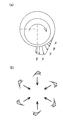
- FIG. 9 is an explanatory diagram of the centering property (self-centering function) which is the effect of the present invention.
- FIG. 9A is a distribution of pressure generated from the Reynolds equation in the wedge-shaped clearance
- FIG. 9B is always centered because the pressure generated by the rotation acts equally when arranged at the circumferential edge. The pressure toward the head is equal, and the action of suppressing vibrations occurs. This is due to the centering function of the present invention.
Priority Applications (6)
| Application Number | Priority Date | Filing Date | Title |
|---|---|---|---|
| PCT/JP2013/070764 WO2015015599A1 (ja) | 2013-07-31 | 2013-07-31 | 低振動形フローティングメタルベアリング |
| US14/236,177 US9581195B2 (en) | 2013-07-31 | 2013-07-31 | Low-vibration floating metal bearing |
| JP2013536342A JP5477930B1 (ja) | 2013-07-31 | 2013-07-31 | 低振動形フローティングメタルベアリング |
| CN201380002524.8A CN104583620B (zh) | 2013-07-31 | 2013-07-31 | 低振动型浮动衬套轴承 |
| EP13834367.8A EP2998596B1 (en) | 2013-07-31 | 2013-07-31 | Low vibration floating metal bearing |
| HK16110970.5A HK1222895A1 (zh) | 2013-07-31 | 2016-09-19 | 低振動型浮動襯套軸承 |
Applications Claiming Priority (1)
| Application Number | Priority Date | Filing Date | Title |
|---|---|---|---|
| PCT/JP2013/070764 WO2015015599A1 (ja) | 2013-07-31 | 2013-07-31 | 低振動形フローティングメタルベアリング |
Publications (1)
| Publication Number | Publication Date |
|---|---|
| WO2015015599A1 true WO2015015599A1 (ja) | 2015-02-05 |
Family
ID=50749904
Family Applications (1)
| Application Number | Title | Priority Date | Filing Date |
|---|---|---|---|
| PCT/JP2013/070764 WO2015015599A1 (ja) | 2013-07-31 | 2013-07-31 | 低振動形フローティングメタルベアリング |
Country Status (6)
| Country | Link |
|---|---|
| US (1) | US9581195B2 (zh) |
| EP (1) | EP2998596B1 (zh) |
| JP (1) | JP5477930B1 (zh) |
| CN (1) | CN104583620B (zh) |
| HK (1) | HK1222895A1 (zh) |
| WO (1) | WO2015015599A1 (zh) |
Cited By (2)
| Publication number | Priority date | Publication date | Assignee | Title |
|---|---|---|---|---|
| WO2019097782A1 (ja) * | 2017-11-20 | 2019-05-23 | 株式会社 中村製作所 | アルミニウム合金製フローティングメタルベアリング |
| WO2019097781A1 (ja) * | 2017-11-20 | 2019-05-23 | 株式会社 中村製作所 | アルミニウム合金製フローティングメタルベアリング |
Families Citing this family (7)
| Publication number | Priority date | Publication date | Assignee | Title |
|---|---|---|---|---|
| JP6370933B2 (ja) | 2015-02-10 | 2018-08-08 | 三菱重工エンジン&ターボチャージャ株式会社 | 浮動ブッシュ軸受装置及びこれを備える過給機 |
| KR20180105673A (ko) * | 2016-02-02 | 2018-09-28 | 보르그워너 인코퍼레이티드 | 베어링 및 그의 제조 및 사용방법 |
| DE102016224094A1 (de) * | 2016-12-05 | 2018-06-07 | Bosch Mahle Turbo Systems Gmbh & Co. Kg | Lagerbuchse und zugehörige Ladeeinrichtung |
| US10557498B1 (en) | 2018-10-12 | 2020-02-11 | Borgwarner Inc. | Full-floating bearing and turbocharger including the same |
| DE102019218117A1 (de) * | 2019-11-25 | 2021-05-27 | Zf Friedrichshafen Ag | Selbstheilendes Gleitlager |
| PL3834922T3 (pl) * | 2019-12-11 | 2022-08-01 | Alfa Laval Corporate Ab | Wspornik wału do podparcia wału mieszadła i mieszadło |
| CN111637152B (zh) * | 2020-05-15 | 2021-12-03 | 大连理工大学 | 一种用于高低温大范围温度环境的金属-陶瓷复合轴颈 |
Citations (8)
| Publication number | Priority date | Publication date | Assignee | Title |
|---|---|---|---|---|
| JPS61201917A (ja) * | 1985-03-05 | 1986-09-06 | Mitsubishi Heavy Ind Ltd | 浮動ブシユ軸受 |
| JPH01193409A (ja) * | 1988-01-26 | 1989-08-03 | Ishikawajima Harima Heavy Ind Co Ltd | フローテイングメタルを備えた軸受 |
| JP2517541Y2 (ja) | 1988-09-28 | 1996-11-20 | アイシン精機株式会社 | ターボチャージャの軸受機構 |
| JPH11336744A (ja) * | 1998-05-28 | 1999-12-07 | Ishikawajima Harima Heavy Ind Co Ltd | 波状軸受 |
| JP2008111502A (ja) | 2006-10-31 | 2008-05-15 | Toyota Motor Corp | 軸受構造 |
| JP2008190498A (ja) | 2007-02-07 | 2008-08-21 | Toyota Motor Corp | ターボチャージャの軸受構造 |
| JP2012207584A (ja) * | 2011-03-29 | 2012-10-25 | Mitsubishi Heavy Ind Ltd | ターボチャージャおよびフローティングブッシュ製造方法 |
| JP2013079591A (ja) * | 2011-10-03 | 2013-05-02 | Ihi Corp | 過給機 |
Family Cites Families (13)
| Publication number | Priority date | Publication date | Assignee | Title |
|---|---|---|---|---|
| DE332357C (de) | 1921-01-29 | Jenaer Glaswerk Schott & Gen | Einschluss-Fieberthermometer | |
| DE1065671B (de) | 1952-11-07 | 1959-09-17 | Neckars ulm Alfred Buske (Wurtt) | Verfahren zur erzeugung keilfoermiger schniertaschen unter Druckanwendung bei aufeinandergleitenden oder ineinandergefuehrten Maschinenteilen, wie vorzugsweise in Lagern |
| US3560064A (en) * | 1969-01-03 | 1971-02-02 | Garrett Corp | Servo controlled fluid bearing |
| GB1428733A (en) * | 1973-04-06 | 1976-03-17 | Woollenweber W E | Bearing structure |
| US4427309A (en) * | 1980-03-24 | 1984-01-24 | The Garrett Corporation | Turbocharger shaft bearing |
| JPS5999112A (ja) * | 1982-11-29 | 1984-06-07 | Mitsubishi Heavy Ind Ltd | すべり軸受 |
| DE3332357C1 (de) * | 1983-09-08 | 1985-04-04 | Klein, Schanzlin & Becker Ag, 6710 Frankenthal | Hydrostatisch-hydrodynamisches Hybrid-Mehrgleitflaechenradiallager |
| US4747705A (en) * | 1987-06-26 | 1988-05-31 | United Technologies Corporation | Power shaped multipad hydrodynamic journal bearing |
| JP3362593B2 (ja) * | 1995-03-13 | 2003-01-07 | 住友電気工業株式会社 | 動圧気体軸受構造 |
| US5909966A (en) * | 1995-12-20 | 1999-06-08 | Ricoh Company, Ltd. | Self-acting air bearing |
| JP2002213248A (ja) * | 2001-01-16 | 2002-07-31 | Nippon Soken Inc | ターボチャージャの軸受装置 |
| JP2002213450A (ja) * | 2001-01-23 | 2002-07-31 | Hitachi Ltd | 浮動ブッシュ軸受、およびそれを具備したターボチャージャ |
| DE102009007696A1 (de) * | 2009-02-05 | 2010-08-12 | Bosch Mahle Turbo Systems Gmbh & Co. Kg | Lageranordnung |
-
2013
- 2013-07-31 CN CN201380002524.8A patent/CN104583620B/zh active Active
- 2013-07-31 EP EP13834367.8A patent/EP2998596B1/en active Active
- 2013-07-31 WO PCT/JP2013/070764 patent/WO2015015599A1/ja active Application Filing
- 2013-07-31 US US14/236,177 patent/US9581195B2/en active Active
- 2013-07-31 JP JP2013536342A patent/JP5477930B1/ja active Active
-
2016
- 2016-09-19 HK HK16110970.5A patent/HK1222895A1/zh unknown
Patent Citations (8)
| Publication number | Priority date | Publication date | Assignee | Title |
|---|---|---|---|---|
| JPS61201917A (ja) * | 1985-03-05 | 1986-09-06 | Mitsubishi Heavy Ind Ltd | 浮動ブシユ軸受 |
| JPH01193409A (ja) * | 1988-01-26 | 1989-08-03 | Ishikawajima Harima Heavy Ind Co Ltd | フローテイングメタルを備えた軸受 |
| JP2517541Y2 (ja) | 1988-09-28 | 1996-11-20 | アイシン精機株式会社 | ターボチャージャの軸受機構 |
| JPH11336744A (ja) * | 1998-05-28 | 1999-12-07 | Ishikawajima Harima Heavy Ind Co Ltd | 波状軸受 |
| JP2008111502A (ja) | 2006-10-31 | 2008-05-15 | Toyota Motor Corp | 軸受構造 |
| JP2008190498A (ja) | 2007-02-07 | 2008-08-21 | Toyota Motor Corp | ターボチャージャの軸受構造 |
| JP2012207584A (ja) * | 2011-03-29 | 2012-10-25 | Mitsubishi Heavy Ind Ltd | ターボチャージャおよびフローティングブッシュ製造方法 |
| JP2013079591A (ja) * | 2011-10-03 | 2013-05-02 | Ihi Corp | 過給機 |
Cited By (2)
| Publication number | Priority date | Publication date | Assignee | Title |
|---|---|---|---|---|
| WO2019097782A1 (ja) * | 2017-11-20 | 2019-05-23 | 株式会社 中村製作所 | アルミニウム合金製フローティングメタルベアリング |
| WO2019097781A1 (ja) * | 2017-11-20 | 2019-05-23 | 株式会社 中村製作所 | アルミニウム合金製フローティングメタルベアリング |
Also Published As
| Publication number | Publication date |
|---|---|
| EP2998596B1 (en) | 2020-05-13 |
| EP2998596A4 (en) | 2016-12-14 |
| CN104583620B (zh) | 2018-01-02 |
| EP2998596A1 (en) | 2016-03-23 |
| CN104583620A (zh) | 2015-04-29 |
| HK1222895A1 (zh) | 2017-07-14 |
| US20160223014A1 (en) | 2016-08-04 |
| JP5477930B1 (ja) | 2014-04-23 |
| JPWO2015015599A1 (ja) | 2017-03-02 |
| US9581195B2 (en) | 2017-02-28 |
Similar Documents
| Publication | Publication Date | Title |
|---|---|---|
| JP5477930B1 (ja) | 低振動形フローティングメタルベアリング | |
| KR101277463B1 (ko) | 다중 두께 막 층 베어링 카트리지와 하우징 | |
| US7670056B2 (en) | Stepped outer diameter semi-floating bearing | |
| CA2807351C (en) | Hydrodynamic axial bearing | |
| US9599119B2 (en) | Bearing device for turbocharger | |
| JP4874491B2 (ja) | 軸受 | |
| US9797303B2 (en) | Turbocharger with thrust bearing providing combined journal and thrust bearing functions | |
| JPWO2013099600A1 (ja) | 過給機のスラスト軸受装置 | |
| JP5863422B2 (ja) | スラスト軸受及び回転機械 | |
| CN104718387A (zh) | 用于轴颈轴承的端面油构造 | |
| JP2011153668A (ja) | 軸受装置 | |
| JP2013011251A5 (zh) | ||
| JP2009167872A (ja) | 過給機 | |
| US10077802B2 (en) | Tilting pad journal bearing assembly | |
| JP2016191465A (ja) | 軸受装置及び排気ガスターボチャージャー | |
| JP6469716B2 (ja) | 排気ガスターボチャージャーのための軸受装置および排気ガスターボチャージャー | |
| JP6595572B2 (ja) | 半割スラスト軸受 | |
| JP2010116944A (ja) | 浮動ブッシュ軸受式の軸受装置及びこれを備える内燃機関の過給機 | |
| CN111005936A (zh) | 一种空气轴承、转子系统及微型燃气轮机 | |
| JP2002070570A (ja) | ターボチャージャの軸受構造 | |
| CN110939513A (zh) | 一种转子系统及微型燃气轮机 | |
| CN213235142U (zh) | 一种新型涡轮转子轴及涡轮增压器 | |
| CN211343131U (zh) | 一种转子系统及微型燃气轮机 | |
| CN211343128U (zh) | 一种转子系统及微型燃气轮机 | |
| KR20170135408A (ko) | 베어링 픽서 |
Legal Events
| Date | Code | Title | Description |
|---|---|---|---|
| ENP | Entry into the national phase |
Ref document number: 2013536342 Country of ref document: JP Kind code of ref document: A |
|
| WWE | Wipo information: entry into national phase |
Ref document number: 14236177 Country of ref document: US |
|
| WWE | Wipo information: entry into national phase |
Ref document number: 2013834367 Country of ref document: EP |
|
| 121 | Ep: the epo has been informed by wipo that ep was designated in this application |
Ref document number: 13834367 Country of ref document: EP Kind code of ref document: A1 |
|
| NENP | Non-entry into the national phase |
Ref country code: DE |