WO2015012248A1 - 超純水製造システム、超純水製造供給システム及びその洗浄方法 - Google Patents
超純水製造システム、超純水製造供給システム及びその洗浄方法 Download PDFInfo
- Publication number
- WO2015012248A1 WO2015012248A1 PCT/JP2014/069282 JP2014069282W WO2015012248A1 WO 2015012248 A1 WO2015012248 A1 WO 2015012248A1 JP 2014069282 W JP2014069282 W JP 2014069282W WO 2015012248 A1 WO2015012248 A1 WO 2015012248A1
- Authority
- WO
- WIPO (PCT)
- Prior art keywords
- water
- removal membrane
- membrane device
- ultrapure water
- particulate removal
- Prior art date
- Legal status (The legal status is an assumption and is not a legal conclusion. Google has not performed a legal analysis and makes no representation as to the accuracy of the status listed.)
- Ceased
Links
Images


Classifications
-
- C—CHEMISTRY; METALLURGY
- C02—TREATMENT OF WATER, WASTE WATER, SEWAGE, OR SLUDGE
- C02F—TREATMENT OF WATER, WASTE WATER, SEWAGE, OR SLUDGE
- C02F9/00—Multistage treatment of water, waste water or sewage
-
- B—PERFORMING OPERATIONS; TRANSPORTING
- B01—PHYSICAL OR CHEMICAL PROCESSES OR APPARATUS IN GENERAL
- B01D—SEPARATION
- B01D61/00—Processes of separation using semi-permeable membranes, e.g. dialysis, osmosis or ultrafiltration; Apparatus, accessories or auxiliary operations specially adapted therefor
- B01D61/02—Reverse osmosis; Hyperfiltration ; Nanofiltration
- B01D61/025—Reverse osmosis; Hyperfiltration
- B01D61/026—Reverse osmosis; Hyperfiltration comprising multiple reverse osmosis steps
-
- B—PERFORMING OPERATIONS; TRANSPORTING
- B01—PHYSICAL OR CHEMICAL PROCESSES OR APPARATUS IN GENERAL
- B01D—SEPARATION
- B01D61/00—Processes of separation using semi-permeable membranes, e.g. dialysis, osmosis or ultrafiltration; Apparatus, accessories or auxiliary operations specially adapted therefor
- B01D61/14—Ultrafiltration; Microfiltration
- B01D61/145—Ultrafiltration
- B01D61/146—Ultrafiltration comprising multiple ultrafiltration steps
-
- B—PERFORMING OPERATIONS; TRANSPORTING
- B01—PHYSICAL OR CHEMICAL PROCESSES OR APPARATUS IN GENERAL
- B01D—SEPARATION
- B01D61/00—Processes of separation using semi-permeable membranes, e.g. dialysis, osmosis or ultrafiltration; Apparatus, accessories or auxiliary operations specially adapted therefor
- B01D61/58—Multistep processes
-
- B—PERFORMING OPERATIONS; TRANSPORTING
- B01—PHYSICAL OR CHEMICAL PROCESSES OR APPARATUS IN GENERAL
- B01D—SEPARATION
- B01D65/00—Accessories or auxiliary operations, in general, for separation processes or apparatus using semi-permeable membranes
- B01D65/02—Membrane cleaning or sterilisation ; Membrane regeneration
-
- B—PERFORMING OPERATIONS; TRANSPORTING
- B08—CLEANING
- B08B—CLEANING IN GENERAL; PREVENTION OF FOULING IN GENERAL
- B08B3/00—Cleaning by methods involving the use or presence of liquid or steam
- B08B3/04—Cleaning involving contact with liquid
- B08B3/10—Cleaning involving contact with liquid with additional treatment of the liquid or of the object being cleaned, e.g. by heat, by electricity or by vibration
- B08B3/14—Removing waste, e.g. labels, from cleaning liquid
-
- B—PERFORMING OPERATIONS; TRANSPORTING
- B08—CLEANING
- B08B—CLEANING IN GENERAL; PREVENTION OF FOULING IN GENERAL
- B08B9/00—Cleaning hollow articles by methods or apparatus specially adapted thereto
- B08B9/02—Cleaning pipes or tubes or systems of pipes or tubes
- B08B9/027—Cleaning the internal surfaces; Removal of blockages
-
- B—PERFORMING OPERATIONS; TRANSPORTING
- B08—CLEANING
- B08B—CLEANING IN GENERAL; PREVENTION OF FOULING IN GENERAL
- B08B9/00—Cleaning hollow articles by methods or apparatus specially adapted thereto
- B08B9/02—Cleaning pipes or tubes or systems of pipes or tubes
- B08B9/027—Cleaning the internal surfaces; Removal of blockages
- B08B9/032—Cleaning the internal surfaces; Removal of blockages by the mechanical action of a moving fluid, e.g. by flushing
-
- C—CHEMISTRY; METALLURGY
- C02—TREATMENT OF WATER, WASTE WATER, SEWAGE, OR SLUDGE
- C02F—TREATMENT OF WATER, WASTE WATER, SEWAGE, OR SLUDGE
- C02F1/00—Treatment of water, waste water, or sewage
- C02F1/44—Treatment of water, waste water, or sewage by dialysis, osmosis or reverse osmosis
- C02F1/444—Treatment of water, waste water, or sewage by dialysis, osmosis or reverse osmosis by ultrafiltration or microfiltration
-
- B—PERFORMING OPERATIONS; TRANSPORTING
- B01—PHYSICAL OR CHEMICAL PROCESSES OR APPARATUS IN GENERAL
- B01D—SEPARATION
- B01D2311/00—Details relating to membrane separation process operations and control
- B01D2311/26—Further operations combined with membrane separation processes
- B01D2311/2623—Ion-Exchange
-
- B—PERFORMING OPERATIONS; TRANSPORTING
- B01—PHYSICAL OR CHEMICAL PROCESSES OR APPARATUS IN GENERAL
- B01D—SEPARATION
- B01D2311/00—Details relating to membrane separation process operations and control
- B01D2311/26—Further operations combined with membrane separation processes
- B01D2311/2692—Sterilization
-
- B—PERFORMING OPERATIONS; TRANSPORTING
- B01—PHYSICAL OR CHEMICAL PROCESSES OR APPARATUS IN GENERAL
- B01D—SEPARATION
- B01D2317/00—Membrane module arrangements within a plant or an apparatus
- B01D2317/04—Elements in parallel
-
- B—PERFORMING OPERATIONS; TRANSPORTING
- B01—PHYSICAL OR CHEMICAL PROCESSES OR APPARATUS IN GENERAL
- B01D—SEPARATION
- B01D61/00—Processes of separation using semi-permeable membranes, e.g. dialysis, osmosis or ultrafiltration; Apparatus, accessories or auxiliary operations specially adapted therefor
- B01D61/02—Reverse osmosis; Hyperfiltration ; Nanofiltration
- B01D61/025—Reverse osmosis; Hyperfiltration
-
- B—PERFORMING OPERATIONS; TRANSPORTING
- B01—PHYSICAL OR CHEMICAL PROCESSES OR APPARATUS IN GENERAL
- B01D—SEPARATION
- B01D61/00—Processes of separation using semi-permeable membranes, e.g. dialysis, osmosis or ultrafiltration; Apparatus, accessories or auxiliary operations specially adapted therefor
- B01D61/14—Ultrafiltration; Microfiltration
- B01D61/145—Ultrafiltration
-
- B—PERFORMING OPERATIONS; TRANSPORTING
- B01—PHYSICAL OR CHEMICAL PROCESSES OR APPARATUS IN GENERAL
- B01D—SEPARATION
- B01D61/00—Processes of separation using semi-permeable membranes, e.g. dialysis, osmosis or ultrafiltration; Apparatus, accessories or auxiliary operations specially adapted therefor
- B01D61/14—Ultrafiltration; Microfiltration
- B01D61/147—Microfiltration
-
- C—CHEMISTRY; METALLURGY
- C02—TREATMENT OF WATER, WASTE WATER, SEWAGE, OR SLUDGE
- C02F—TREATMENT OF WATER, WASTE WATER, SEWAGE, OR SLUDGE
- C02F1/00—Treatment of water, waste water, or sewage
- C02F1/20—Treatment of water, waste water, or sewage by degassing, i.e. liberation of dissolved gases
-
- C—CHEMISTRY; METALLURGY
- C02—TREATMENT OF WATER, WASTE WATER, SEWAGE, OR SLUDGE
- C02F—TREATMENT OF WATER, WASTE WATER, SEWAGE, OR SLUDGE
- C02F1/00—Treatment of water, waste water, or sewage
- C02F1/30—Treatment of water, waste water, or sewage by irradiation
- C02F1/32—Treatment of water, waste water, or sewage by irradiation with ultraviolet light
-
- C—CHEMISTRY; METALLURGY
- C02—TREATMENT OF WATER, WASTE WATER, SEWAGE, OR SLUDGE
- C02F—TREATMENT OF WATER, WASTE WATER, SEWAGE, OR SLUDGE
- C02F1/00—Treatment of water, waste water, or sewage
- C02F1/30—Treatment of water, waste water, or sewage by irradiation
- C02F1/32—Treatment of water, waste water, or sewage by irradiation with ultraviolet light
- C02F1/325—Irradiation devices or lamp constructions
-
- C—CHEMISTRY; METALLURGY
- C02—TREATMENT OF WATER, WASTE WATER, SEWAGE, OR SLUDGE
- C02F—TREATMENT OF WATER, WASTE WATER, SEWAGE, OR SLUDGE
- C02F1/00—Treatment of water, waste water, or sewage
- C02F1/42—Treatment of water, waste water, or sewage by ion-exchange
-
- C—CHEMISTRY; METALLURGY
- C02—TREATMENT OF WATER, WASTE WATER, SEWAGE, OR SLUDGE
- C02F—TREATMENT OF WATER, WASTE WATER, SEWAGE, OR SLUDGE
- C02F1/00—Treatment of water, waste water, or sewage
- C02F1/44—Treatment of water, waste water, or sewage by dialysis, osmosis or reverse osmosis
- C02F1/441—Treatment of water, waste water, or sewage by dialysis, osmosis or reverse osmosis by reverse osmosis
-
- C—CHEMISTRY; METALLURGY
- C02—TREATMENT OF WATER, WASTE WATER, SEWAGE, OR SLUDGE
- C02F—TREATMENT OF WATER, WASTE WATER, SEWAGE, OR SLUDGE
- C02F2103/00—Nature of the water, waste water, sewage or sludge to be treated
- C02F2103/02—Non-contaminated water, e.g. for industrial water supply
- C02F2103/04—Non-contaminated water, e.g. for industrial water supply for obtaining ultra-pure water
-
- C—CHEMISTRY; METALLURGY
- C02—TREATMENT OF WATER, WASTE WATER, SEWAGE, OR SLUDGE
- C02F—TREATMENT OF WATER, WASTE WATER, SEWAGE, OR SLUDGE
- C02F2301/00—General aspects of water treatment
- C02F2301/04—Flow arrangements
- C02F2301/043—Treatment of partial or bypass streams
-
- C—CHEMISTRY; METALLURGY
- C02—TREATMENT OF WATER, WASTE WATER, SEWAGE, OR SLUDGE
- C02F—TREATMENT OF WATER, WASTE WATER, SEWAGE, OR SLUDGE
- C02F2303/00—Specific treatment goals
- C02F2303/04—Disinfection
-
- C—CHEMISTRY; METALLURGY
- C02—TREATMENT OF WATER, WASTE WATER, SEWAGE, OR SLUDGE
- C02F—TREATMENT OF WATER, WASTE WATER, SEWAGE, OR SLUDGE
- C02F2303/00—Specific treatment goals
- C02F2303/16—Regeneration of sorbents, filters
Definitions
- the present invention relates to an ultrapure water production system, an ultrapure water production supply system, and a cleaning method thereof. Specifically, the present invention relates to an ultrapure water production system capable of supplying ultrapure water having a good water quality to a water use point (use point) in a short time after the sterilization washing process, and a cleaning method thereof, and an ultrapure water. The present invention relates to a water production supply system and a cleaning method thereof.
- ultrapure water is used as cleaning water for components.
- Ultrapure water quality applied to semiconductor manufacturing plants and wafer manufacturing plants is strict, for example, resistivity (specific resistance value): 18.2 M ⁇ ⁇ cm or more, fine particles: particle size of 50 nm or more, 100 or less, particle size of 20 nm or more 1,000 or less, viable bacteria: 1 / L or less, TOC (Total Organic Carbon): 0.5 ⁇ g / L or less, total silicon: 0.05 ⁇ g / L or less, metals: 0.1 ng / L or less, ion Class: 5 ng / L or less.
- Fine particles such as dust, silica, and aluminum in the air mixed in the system during construction (new establishment, expansion, modification) or maintenance of the ultrapure water production system, particles contained in water such as dead bodies of bacteria, iron rust, In addition, fine particles made of shavings such as membranes and piping generated in the manufacturing process remain in the system.
- the fine particles are excluded from the system, and cleaning with an alkaline solution is performed so that the number of fine particles having a particle size of 50 nm or more in ultrapure water is 1000 / L or less (Patent Document 1).
- Patent Documents 2 and 3 describe a sterilization method of an ultrapure water production system for suppressing viable bacteria in ultrapure water.
- JP 2000-317413 A JP 2002-166283 A JP 2004-275881 A
- the above-described conventional sterilization cleaning method has the following problems. i) At the time of sterilization cleaning, dust (contaminant) in the ultrapure water production system is captured by the particulate removal film in the ultrapure water production system. Secondary contamination, in which trapped contaminants come off the membrane surface and enter the water, continues for a long time. Therefore, it is not possible to supply ultrapure water with good water quality to the water use point in a short time after sterilization washing. ii) In order to avoid the above problem, if sterilization washing is performed without installing a particulate removal membrane, the contaminants in the ultrapure water production system are supplied to the supply pipe that supplies ultrapure water to the water use point. The For this reason, after sterilization and cleaning, ultrapure water with good water quality cannot be obtained at the water use point in a short time.
- the present invention solves the above-mentioned conventional problems, and does not supply contaminants in the ultrapure water production system to the supply pipe to the water use point at the time of sterilization cleaning.
- Ultrapure water production system capable of supplying ultrapure water with good water quality to a water use point (use point) in a short time while preventing system contamination due to contaminants trapped by the removal membrane, and its production method
- Another object is to provide an ultrapure water production and supply system and a cleaning method thereof.
- the present inventors have provided a second fine particle removal film device separately from the first fine particle removal film device provided in the ultrapure water production system, and have been sterilized. At the time of washing and flushing after sterilization washing, sterilization water and flushing water are passed through the second particulate removal membrane device, and the first particulate removal membrane device is used only on the water supply side without allowing the washing water to pass through the membrane. It has been found that the above-mentioned problems can be solved by performing cleaning or replacing the first particulate removal membrane apparatus with a particulate removal membrane that has been sterilized in advance without passing washing water.
- the present invention has been achieved on the basis of such knowledge, and the gist thereof is as follows.
- the ultrapure water production system including at least a tank, a pump, a heat exchanger, an ultraviolet ray apparatus, an ion exchange apparatus, and a first particulate removal membrane apparatus is passed through sterilizing water and flushing water, respectively.
- An ultrapure water production system cleaning method for performing sterilization cleaning of a pure water manufacturing system and flushing cleaning after sterilization cleaning, wherein a second particle removal film device is provided in parallel with the first particle removal film device. (I-1) to (I-3) are subjected to a cleaning step, and after the cleaning step, the heat exchanger, the ultraviolet device, and the ion exchange are performed without passing water through the second particulate removal membrane device.
- a method for cleaning an ultrapure water production system wherein ultrapure water is produced by passing water through the apparatus and the first particulate removal membrane apparatus.
- (I-1) A part of the sterilizing water and flushing water is supplied to the first fine particle removal film apparatus, and the first fine particle removal is performed without passing through the fine particle removal film of the first fine particle removal film apparatus.
- the membrane device is discharged from the water supply side to the concentrated water side, and the remaining portion is passed through the second particulate removal membrane device.
- I-2) The entire amount of sterilizing water and flushing water is passed through the second particulate removal membrane device, and the particulate removal membrane of the first particulate removal membrane device is replaced with a particulate removal membrane that has been previously sterilized.
- the particulate removal membrane of the first particulate removal membrane device is replaced with a pipe, and a part of the sterilizing water and flushing water is passed through the first particulate removal membrane device, and the remainder is After passing water through the second particulate removal membrane device, the pipe of the first particulate removal membrane device is replaced with a particulate removal membrane that has been previously sterilized.
- the ultrapure water production system provided with at least a tank, a pump, a heat exchanger, an ultraviolet ray apparatus, an ion exchange apparatus, and a first particulate removal membrane apparatus is supplied with sterilizing water and flushing water, respectively.
- a cleaning method for an ultrapure water manufacturing system that performs sterilization cleaning of a pure water manufacturing system and flushing cleaning after sterilization cleaning, between the final pump of the ultrapure water manufacturing system and the first particulate removal membrane device
- a second particulate removal membrane device is provided so as to allow water to pass through the second particulate removal membrane device, and any one of the following cleaning steps (II-1) to (II-3) is performed: After the cleaning step, the second particulate removal membrane device is bypassed and passed through the heat exchanger, ultraviolet device, ion exchange device, and first particulate removal membrane device to produce ultrapure water.
- ultrapure water production system characterized by Kiyoshi way.
- a bypass pipe for bypassing the first particulate removal membrane device is provided, and sterilizing water and flushing water are passed through the second particulate removal membrane device and permeated through the second particulate removal membrane device. Concentrated water is supplied from the water supply side of the first particulate removal membrane device without supplying a part of the water to the first particulate removal membrane device and passing through the particulate removal membrane of the first particulate removal membrane device. The remaining portion is drained to the bypass pipe.
- a bypass pipe for bypassing the first particulate removal membrane device is provided, and sterilizing water and flushing water are passed through the second particulate removal membrane device and the bypass piping to remove the first particulate removal.
- the particulate removal film of the membrane apparatus is replaced with a particulate removal film that has been sterilized in advance.
- II-3 After exchanging the particulate removal membrane of the first particulate removal membrane device with piping, sterilizing water and flushing water are passed through the second particulate removal membrane device and the first particulate removal membrane device. Thereafter, the pipe of the first particle removal membrane device is replaced with a particle removal membrane that has been previously sterilized.
- the ultrapure water production system including at least a tank, a pump, a heat exchanger, an ultraviolet ray device, an ion exchange device, and a first particulate removal membrane device is passed through sterilizing water and flushing water, respectively.
- a cleaning method of an ultrapure water production system that performs sterilization cleaning of a pure water production system and flushing cleaning after sterilization cleaning, wherein a second particle removal film device is provided at a stage subsequent to the first particle removal film device. 2 is provided so that water can be bypassed, and the cleaning process of any one of (III-1) to (III-3) below is performed, and after the cleaning process, the second particulate removal is performed.
- Ultrapure water is produced by bypassing the membrane device and passing water through the heat exchanger, ultraviolet device, ion exchange device, and first particulate removal membrane device.
- Method. (III-1) A bypass for bypassing the first particulate removal membrane device is provided, and a part of the sterilizing water and flushing water is supplied to the first particulate removal membrane device, and the first particulate removal membrane device is provided. Without passing through the fine particle removal membrane, the water is discharged from the water supply side of the first fine particle removal membrane device to the concentrated water side, the remaining portion is passed through the bypass pipe, and then passed through the second fine particle removal membrane device. To do.
- (III-2) A bypass pipe that bypasses the first particulate removal membrane device is provided, and sterilizing water and flushing water are passed through the bypass piping and the second particulate removal membrane device to remove the first particulate removal device.
- the particulate removal film of the membrane apparatus is replaced with a particulate removal film that has been sterilized in advance.
- (III-3) After exchanging the particulate removal membrane of the first particulate removal membrane device with a pipe, sterilizing water and flushing water are passed through the first particulate removal membrane device and the second particulate removal membrane device. Thereafter, the pipe of the first particle removal membrane device is replaced with a particle removal membrane that has been previously sterilized.
- the fine particle removal film that has been sterilized in advance is sterilized and washed with at least one sterilizing water containing an oxidant-containing water, an organic solution, or hot water.
- An ultrapure water production system including at least a tank, a pump, a heat exchanger, an ultraviolet ray device, an ion exchange device, and a first particulate removal membrane device, and ultrapure water produced by the ultrapure water production system Dispense sterilizing water and flushing water to an ultrapure water production and supply system comprising a supply pipe that supplies water to the water use point and a return pipe that returns surplus water from the water use point to the ultrapure water production system.
- the ultrapure water production and supply system according to any one of claims 1 to 6, wherein the ultrapure water production and supply system performs a sterilization washing and a flushing washing after the sterilization washing.
- the ultrapure water production system is washed by the washing method, and the sterilizing water and the flushing water that have passed through the second particulate removing membrane device in the washing step are passed through the supply pipe and the return pipe.
- the method of cleaning an ultrapure water production and supply system characterized in that discharging into the following systems outside the.
- the first particulate removal membrane device originally provided in the ultrapure water production system without allowing the cleaning water to pass through the membrane, Either the water supply side is washed and discharged out of the system, or the first particulate removal membrane device is replaced with a particulate removal membrane that has been sterilized in advance without passing washing water.
- sterilization water and flushing water are passed through the second particle removal membrane device, and water that has passed through the second particle removal membrane device is supplied to the water use point. To be sent to. For this reason, no pollutant is supplied to the supply pipe, and the problem ii) is solved.
- ultrapure water with good water quality can be supplied to the water use point in a short time after sterilization cleaning.
- 1 is a system diagram of an ultrapure water production system and an ultrapure water production supply system according to a first embodiment.
- 1 is a system diagram of an ultrapure water production system and an ultrapure water production supply system according to a first embodiment.
- 1 is a system diagram of an ultrapure water production system and an ultrapure water production supply system according to a first embodiment.
- 1 is a system diagram of an ultrapure water production system and an ultrapure water production supply system according to a first embodiment.
- 1 is a system diagram of an ultrapure water production system and an ultrapure water production supply system according to a first embodiment.
- 1 is a system diagram of an ultrapure water production system and an ultrapure water production supply system according to a first embodiment.
- 1 is a system diagram of an ultrapure water production system and an ultrapure water production supply system according to a first embodiment.
- 1 is a system diagram of an ultrapure water production system and an ultrapure water production supply system according to a first embodiment.
- 1 is a system diagram of an ultrapure water production system and an ultrapure water production supply system according to a first embodiment.
- 1 is a system diagram of an ultrapure water production system and an ultrapure water production supply system according to a first embodiment.
- 1 is a system diagram of an ultrapure water production system and an ultrapure water production supply system according to a first embodiment.
- 1 is a system diagram of an ultrapure water production system and an ultrapure water production supply system according to a first embodiment.
- 1 is a system diagram of an ultrapure water production system and an ultrapure water production supply system according to a first embodiment. It is a systematic diagram of the ultrapure water production system and ultrapure water production supply system which concern on 2nd Embodiment. It is a systematic diagram of the ultrapure water production system and ultrapure water production supply system which concern on 2nd Embodiment. It is a systematic diagram of the ultrapure water production system and ultrapure water production supply system which concern on 2nd Embodiment. It is a systematic diagram of the ultrapure water production system and ultrapure water production supply system which concern on 2nd Embodiment. It is a systematic diagram of the ultrapure water production system and ultrapure water production supply system which concern on 2nd Embodiment. It is a systematic diagram of the ultrapure water production system and ultrapure water production supply system which concern on 2nd Embodiment.
- the pure water in this invention and an ultrapure water shall have the following water quality.
- Primary pure water resistivity 10 M ⁇ ⁇ cm or more TOC 100 ⁇ g / L or less
- Ultrapure water resistivity 15 M ⁇ ⁇ cm or more TOC 1 ⁇ g / L or less
- FIG. 1 is a system diagram of an ultrapure water production system and an ultrapure water supply piping system for explaining a cleaning method of the ultrapure water production system and the ultrapure water production supply system according to the first embodiment of the present invention. It is.
- the ultrapure water production system 1 includes a tank 11, a pump 12, a heat exchanger 13, an ultraviolet device (ultraviolet oxidizer) 14, an ion exchanger 15, and a first particulate removal membrane device 16. These devices are connected by piping or tubes. In some cases, a membrane separation device including a reverse osmosis (RO) membrane between the pump 12 and the first particulate removal membrane device 16, a deaeration device, an oxidant removal device, a pump different from the pump 12, and an ion exchange device 15. Different or similar ion exchange devices may be incorporated.
- the ultraviolet device 14 is composed of either a low-pressure ultraviolet oxidizer or an ultraviolet sterilizer depending on the required water quality of ultrapure water.
- the fine particle removal membrane device is composed of an ultrafiltration membrane device (UF), a microfiltration membrane device (MF), or a reverse osmosis membrane device (RO) depending on the required water quality and sterilization conditions of ultrapure water.
- a bypass pipe 15 a that short-circuits the outflow pipe 14 b of the ultraviolet device 14 and the outflow pipe 15 b of the ion exchange apparatus 15 is provided so as to bypass the ion exchange apparatus 15.
- a bypass pipe may be incorporated in the heat exchanger 13 and the ultraviolet device 14.
- a bypass piping 16a, a second particulate removal membrane device 17, and a bypass piping 16b are provided so as to bypass the first particulate removal membrane device 16.
- a first blow pipe 16c is connected to the most downstream side of the bypass pipe 16b.
- the ultrapure water supply piping system 2 includes use points (use points) 3 for ultrapure water and flow paths (pipes or tubes) 21 and 22 for ultrapure water.
- a second blow pipe 22a (FIGS. 4, 5d to 5f, 7, 8) is provided at the most distal end portion of the flow path 22.
- a bypass pipe 2 a is provided between the pipes 21 and 22 so as to bypass the water use point 3.
- a flow path switching valve is provided at a branching part or a joining part of each pipe or tube.
- the primary pure water 4 and the ultrapure water returned from the ultrapure water supply pipe 22 are received in the tank 11.
- the water in the tank 11 (ultra pure water raw water) is sent by the pump 12 and processed in the heat exchanger 13, the ultraviolet ray device 14, the ion exchange device 15, and the first fine particle removal membrane device 16 in order to obtain ultra pure water.
- the pump 12 is sent by the pump 12 and processed in the heat exchanger 13, the ultraviolet ray device 14, the ion exchange device 15, and the first fine particle removal membrane device 16 in order to obtain ultra pure water.
- Primary pure water can be obtained, for example, by treating pretreated raw water with a reverse osmosis (RO) membrane device, treating with an ion exchange device, and further treating with a reverse osmosis membrane.
- Primary pure water can also be obtained by treating pretreated raw water with a multi-bed tower ion exchanger, and further treating with a reverse osmosis (RO) membrane device, an ultraviolet device, an ion exchanger, and a deaerator.
- RO reverse osmosis
- the ultrapure water produced by the ultrapure water production system 1 is sent to the water use point 3 through the flow path 21 and part of it is used, and the unused ultrapure water passes through the flow path 22 and is ultrapure. Return to the water production system 1.
- FIG. 2 When cleaning and sterilizing the ultrapure water production system 1 and the ultrapure water supply piping system 2, FIG. 2 ⁇ FIG. 3 ⁇ FIG. 4 ⁇ FIGS. 5a to 5c ⁇ FIGs. 5d to 5f ⁇ FIGs. 3 ⁇ FIG. Water is passed in the order of FIGS. 5a to 5c ⁇ FIG. 4 ⁇ FIG. 7 ⁇ FIG.
- a pipe or tube represented by a thick solid line indicates that water is flowing
- a pipe or tube represented by a thin solid line indicates that no water is flowing.
- FIG. 2 Cleaning of Second Fine Particle Removal Film Device>
- the ultrapure water obtained from the first particulate removal membrane device 16 is supplied to the use point 3 in the same manner as in FIG.
- a part of the effluent water is supplied from the bypass pipe 16a to the particulate removal membrane device 17 to which no membrane is attached, discharged out of the system from the blow pipe 16c, and blown for a certain time.
- the fine particle removal film is attached to the second fine particle removal film device 17.
- ⁇ Figure 3 Alkaline cleaning> After measuring the fine particles in the blow water from the blow pipe 16c and confirming that the number of fine particles is not more than a prescribed number (for example, 500 particles / L or less of 50 nm or more), the ultrapure water production system 1 and the ultrapure water The supply piping system 2 is washed with alkali. As shown in FIG. 3, valve selection (channel switching) is performed so that water flows by bypassing the ion exchange device 15 and the first particulate removal membrane device 16 of the ultrapure water production system 1. The water level of the tank 11 is adjusted to the minimum level at which the pump does not stop at “level low”.
- a prescribed number for example, 500 particles / L or less of 50 nm or more
- the valves are slightly opened so that the liquid flows through these pipes. Further, the valve is slightly opened so that the liquid also flows through the bypass pipe 2 a of the ultrapure water supply piping system 2.
- the blow pipe 16c is closed.
- the alkali cleaning time is preferably 0.5 Hr or more, particularly about 1 to 2 Hr.
- FIG. 5a Sterilization cleaning method 1>
- the ion exchange device 15 of the ultrapure water production system 1 is bypassed, and water is passed through both the first particulate removal membrane device 16 and the second particulate removal membrane device 17, and the first The fine particle removal membrane device 16 selects the valve so that the sterilizing water that does not permeate the membrane and flows into the water supply side (primary side) of the membrane is discharged from the concentrated water pipe 16d to the outside of the system.
- the bypass pipe is also incorporated in the heat exchanger 13 and the ultraviolet device 14, the line is slightly opened.
- the valve is opened slightly so that the sterilizing water also flows into the bypass pipe 2a of the ultrapure water production and supply system 2.
- the blow pipe 16c is closed. Thereafter, the ultrapure water in the ultrapure water production system 1 and the ultrapure water supply piping system 2 is heated to the required temperature by the heat exchanger 13 as necessary so that the ultrapure water becomes sterilized water, and hydrogen peroxide is injected into the tank 11.
- the ultrapure water production system 1 and the ultrapure water supply piping system 2 are circulated using the pump 12.
- sterilization water does not permeate the first fine particle removal membrane device 16 and only the water supply side of the membrane is sterilized and cleaned.
- the sterilization water supplied to the water supply side of the membrane is one By leaching to the secondary side (permeation side) of the partial membrane, the secondary side of the membrane is also sterilized.
- FIG. 5b Sterilization cleaning method 2>
- bypass the ion exchange device 15 and the first particulate removal membrane device 16 of the ultrapure water production system 1 select a valve so that water is passed through the second particulate removal membrane device 17,
- the water level of the tank 11 is adjusted.
- the bypass pipe is also incorporated in the heat exchanger 13 and the ultraviolet device 14, the line is slightly opened.
- the valve is slightly opened so that the sterilizing water also flows into the bypass pipe 2a of the ultrapure water production and supply system 2.
- the blow pipe 16c is closed.
- the ultrapure water in the ultrapure water production system 1 and the ultrapure water supply piping system 2 is heated to the required temperature by the heat exchanger 13 as necessary so that the ultrapure water becomes sterilized water, and hydrogen peroxide is injected into the tank 11.
- the ultrapure water production system 1 and the ultrapure water supply piping system 2 are circulated using the pump 12.
- FIG. 5c Sterilization cleaning method 3>
- the ion exchange device 15 of the ultrapure water production system 1 is bypassed, and the first particulate removal membrane device 16 and the second particulate removal membrane device 16
- the valve is selected so that water is passed through both of the particulate removal membrane devices 17 and the water level of the tank 11 is adjusted.
- the bypass pipe is also incorporated in the heat exchanger 13 and the ultraviolet device 14, the line is slightly opened.
- the valve is slightly opened so that the sterilizing water also flows into the bypass pipe 2a of the ultrapure water production and supply system 2.
- the blow pipe 16c is closed.
- the ultrapure water in the ultrapure water production system 1 and the ultrapure water supply piping system 2 is heated to the required temperature by the heat exchanger 13 as necessary so that the ultrapure water becomes sterilized water, and hydrogen peroxide is injected into the tank 11.
- the ultrapure water production system 1 and the ultrapure water supply piping system 2 are circulated using the pump 12.
- the sterilization cleaning by the above sterilization cleaning methods 1 to 3 is preferably performed for 0.5 Hr or more, particularly 1 to 2 Hr.
- FIG. 5f the sterilization cleaning method 3 shown in FIG.
- the first pure water 4 is supplied to the tank 11 and the second blow branching from the most distal end of the pipe 22 (downstream from the junction with the bypass pipe 2a).
- the pipe 22 a is opened, and the sterilizing water in the ultrapure water production system 1 and the ultrapure water supply pipe system 2 is pushed out of the system by the primary pure water 4. This flushing is performed until the hydrogen peroxide concentration of the flushing water discharged from the blow pipe 22a becomes 1 mg / L or less.
- the particle removal film of the first particle removal film device 16 is replaced with a particle removal film that has been previously sterilized.
- This membrane exchange may be performed before sterilization and flushing washing.
- the sterilization cleaning method 3 of FIG. 5c is adopted after the above flushing cleaning, the pipe of the first particle removal film device 16 is replaced with a particle removal film that has been previously sterilized.
- FIG. 6 and FIGS. 5a to 5c Second Sterilization Cleaning> After the flushing, the second sterilization cleaning with hydrogen peroxide is performed. The first half water passing method at the time of the second sterilization washing is performed according to FIG.
- the water flow method of FIG. 6 is basically the same as that of FIGS. 5a to 5c, except that the hydrogen peroxide-containing water from the bypass pipe 15a is removed not only by the second particle removal membrane device 17 but also by the first particle removal. It is different from FIGS. 5a to 5c in that water is passed through the membrane device 16 as well.
- the other water flow conditions are the same as in FIGS. 5a to 5c.
- the sterilization cleaning in FIG. 6 is preferably performed for 0.5 Hr or more, particularly about 0.5 to 1 Hr. *
- the process proceeds to the sterilization cleaning shown in FIGS. 5a to 5c, and preferably sterilization cleaning is performed for about 1 to 24 hours, particularly about 2 to 12 hours.
- FIG. 7 Primary finish> Next, primary finishing water flow shown in FIG. 7 is performed.
- the primary finishing water flow is substantially the same as the flushing water flow shown in FIG. 4 except that the water flowing out from the ultraviolet device 14 is passed not only to the bypass pipe 15a but also to the ion exchange device 15. Unlike the process, the other steps are the same as in the case of the flushing shown in FIG.
- the secondary finishing water flow shown in FIG. 8 is performed.
- the second finishing water flow is different from the first finishing water flow shown in FIG. 7 in the following points 1) to 3), and the other points are the same as the first finishing water flow.
- the effluent from the ultraviolet oxidizer 14 is not passed through the bypass pipe 15a, but only through the ion exchanger 15.
- the outflow water of the ion exchange device 15 is passed through both the first particle removal membrane device 16 and the second particle removal membrane device 17.
- the water from the particulate removal membrane devices 16 and 17 is not passed through the water use point 2 but the entire amount is circulated through the bypass pipe 2a.
- This secondary finishing water flow is performed until the quality of the outflow water from the blow pipe 22a becomes the target ultrapure water quality. After the completion of the secondary finishing water flow, the operation returns to the steady operation shown in FIG.
- the second particulate removal membrane device 17 is provided in the bypass piping 15c and 15d of the ion exchange device 15, and the blow piping 16c is provided in the bypass piping 15d.
- the ultrapure water production system 1 and the ultrapure water supply piping system 2 have the same configuration as in FIG.
- the water in the tank 11 (ultra pure water) is fed by the pump 12, and the heat exchanger 13, the ultraviolet device 14, the ion exchange device 15, the first Ultrapure water is produced by sequentially treating the fine particle removal film device 16.
- the ultrapure water produced by the ultrapure water production system 1 is sent to the water use point 3 through the flow path 21 and part of it is used, and the unused ultrapure water passes through the flow path 22 and is ultrapure. Return to the water production system 1.
- FIG. 9 When cleaning and sterilizing the ultrapure water production system 1 and the ultrapure water supply piping system 2, FIG. 9 ⁇ FIG. 10 ⁇ FIG. 11 ⁇ FIGS. 12a to 12c ⁇ FIGs. 12d to 12f ⁇ FIG. 10 ⁇ FIG. Water is passed in the order of FIGS. 12a to 12c ⁇ FIG. 11 ⁇ FIG. 14 ⁇ FIG.
- a pipe or tube represented by a thick solid line indicates that water is flowing
- a pipe or tube represented by a thin solid line indicates that no water is flowing.
- FIG. 9 Cleaning of Second Fine Particle Removal Film Device>
- the ultrapure water obtained from the first particulate removal membrane device 16 is supplied to the use point 3 in the same manner as in FIG.
- a part is supplied from the bypass pipe 15c to the particulate removal membrane device 17 to which no membrane is attached, discharged from the blow pipe 16c to the outside of the system, and blown for a predetermined time.
- the fine particle removal film is attached to the second fine particle removal film device 17.
- ⁇ Figure 10 Alkaline cleaning> After measuring the fine particles in the blow water from the blow pipe 16c and confirming that the number of fine particles is not more than a prescribed number (for example, 500 particles / L or less of 50 nm or more), the ultrapure water production system 1 and the ultrapure water The supply piping system 2 is washed with alkali. As shown in FIG. 10, valve selection (flow path switching) is performed so that water flows by bypassing the ion exchange device 15 and the first particulate removal membrane device 16 of the ultrapure water production system 1. The water level of the tank 11 is adjusted to the minimum level at which the pump does not stop at “level low”.
- a prescribed number for example, 500 particles / L or less of 50 nm or more
- valves When the bypass pipes are also incorporated in the heat exchanger 13 and the ultraviolet device 14, the valves are slightly opened so that the liquid flows through these pipes.
- the valve is slightly opened so that the liquid flows also to the bypass pipe 2a of the ultrapure water supply piping system 2.
- the blow pipe 16c is closed.
- the alkali cleaning time is preferably 0.5 Hr or more, particularly about 1 to 2 Hr.
- FIG. 12a Sterilization cleaning method 1>
- the ion exchange device 15 of the ultrapure water production system 1 is bypassed and water is passed through the second particulate removal membrane device 17, and both the bypass pipes 16 a and 16 b and the first particulate removal membrane device 16 are passed.
- the valve is selected so that water is supplied and the sterilizing water that does not permeate the first particulate removal membrane device 16 and flows into the water supply side (primary side) of the membrane is discharged from the concentrated water pipe 16d to the outside of the system.
- the water level of the tank 11 is adjusted.
- the bypass pipe is also incorporated in the heat exchanger 13 and the ultraviolet device 14, the line is slightly opened.
- the valve is opened slightly so that the sterilizing water also flows into the bypass pipe 2a of the ultrapure water production and supply system 2.
- the blow pipe 16c is closed. Thereafter, the ultrapure water in the ultrapure water production system 1 and the ultrapure water supply piping system 2 is heated to the required temperature by the heat exchanger 13 as necessary so that the ultrapure water becomes sterilized water, and hydrogen peroxide is injected into the tank 11.
- the ultrapure water production system 1 and the ultrapure water supply piping system 2 are circulated using the pump 12.
- sterilization water does not permeate the first fine particle removal membrane device 16 and only the water supply side of the membrane is sterilized and cleaned.
- the sterilization water supplied to the water supply side of the membrane is one By leaching to the secondary side (permeation side) of the partial membrane, the secondary side of the membrane is also sterilized.
- FIG. 12b Sterilization cleaning method 2>
- the ion exchange device 15 of the ultrapure water production system 1 is bypassed to pass through the second particulate removal membrane device 17, the first particulate removal membrane device 16 is bypassed, and the bypass pipes 16a and 16b.
- the valve is selected so that water is passed through the tank 11, and the water level of the tank 11 is adjusted.
- the bypass pipe is also incorporated in the heat exchanger 13 and the ultraviolet device 14, the line is slightly opened.
- the valve is slightly opened so that the sterilizing water also flows into the bypass pipe 2a of the ultrapure water production and supply system 2.
- the blow pipe 16c is closed.
- the ultrapure water in the ultrapure water production system 1 and the ultrapure water supply piping system 2 is heated to the required temperature by the heat exchanger 13 as necessary so that the ultrapure water becomes sterilized water, and hydrogen peroxide is injected into the tank 11
- the ultrapure water production system 1 and the ultrapure water supply piping system 2 are circulated using the pump 12.
- FIG. 12c Sterilization cleaning method 3>
- the ion exchange device 15 of the ultrapure water production system 1 is bypassed to the second fine particle removal film device 17 as shown in FIG.
- the valve is selected so that water is passed through both the first particulate removal membrane device 16 and the bypass pipes 16a and 16b, and the water level of the tank 11 is adjusted.
- the bypass pipe is also incorporated in the heat exchanger 13 and the ultraviolet device 14, the line is slightly opened.
- the valve is slightly opened so that the sterilizing water also flows into the bypass pipe 2a of the ultrapure water production and supply system 2.
- the blow pipe 16c is closed.
- the ultrapure water in the ultrapure water production system 1 and the ultrapure water supply piping system 2 is heated to the required temperature by the heat exchanger 13 as necessary so that the ultrapure water becomes sterilized water, and hydrogen peroxide is injected into the tank 11
- the ultrapure water production system 1 and the ultrapure water supply piping system 2 are circulated using the pump 12.
- the sterilization cleaning by the above sterilization cleaning methods 1 to 3 is preferably performed for 0.5 Hr or more, particularly 1 to 2 Hr.
- FIG. 12f the sterilization cleaning method 3 shown in FIG.
- the first pure water 4 is supplied to the tank 11 and the second blow branching from the most distal end of the pipe 22 (downstream side of the junction with the bypass pipe 2a).
- the pipe 22 a is opened, and the sterilizing water in the ultrapure water production system 1 and the ultrapure water supply pipe system 2 is pushed out of the system by the primary pure water 4. This flushing is performed until the hydrogen peroxide concentration of the flushing water discharged from the blow pipe 22a becomes 1 mg / L or less.
- the particle removal film of the first particle removal film device 16 is replaced with a particle removal film that has been previously sterilized.
- This membrane exchange may be performed before sterilization and flushing washing.
- the pipe of the first particle removal film device 16 is replaced with a particle removal film that has been previously sterilized.
- FIG. 13 and FIGS. 12a to 12c Second Sterilization Cleaning> After the flushing, the second sterilization cleaning with hydrogen peroxide is performed. The first half water passing method at the time of the second sterilization cleaning is performed according to FIG.
- the water flow method in FIG. 13 is basically the same as that in FIGS. 12a to 12c, except that the hydrogen peroxide-containing water from the bypass pipe 15d is used not only in the bypass pipes 16a and 16b but also in the first particulate removal membrane device 16. 12a to 12c is different from that shown in FIGS. Other water flow conditions are the same as in FIGS. 12a to 12c.
- the sterilization cleaning of FIG. 13 is preferably performed for 0.5 Hr or more, particularly about 0.5 to 1 Hr. *
- the process proceeds to the sterilization and cleaning shown in FIGS. 12a to 12c.
- the sterilization and cleaning are performed for about 1 to 24 hours, particularly about 2 to 12 hours.
- FIG. 14 Primary finish> Next, primary finishing water flow shown in FIG. 14 is performed.
- This primary finishing water flow is substantially the same as the flushing water flow shown in FIG. 11 except that the effluent water from the ultraviolet device 14 is passed not only to the fine particle removal membrane device 17 but also to the ion exchange device 15. Is different from the flushing step, and the other steps are the same as those in the flushing shown in FIG.
- FIG. 15 secondary finishing water flow shown in FIG. 15 is performed.
- This secondary finishing water flow is different from the primary finishing water flow of FIG. 14 in the following points 1) to 3), and the other points are the same as the primary finishing water flow.
- the effluent water from the ultraviolet oxidation device 14 is not passed through the fine particle removal membrane device 17 but only through the ion exchange device 15.
- the effluent from the ion exchange device 15 is passed through both the first particulate removal membrane device 16 and the bypass pipes 16a and 16b.
- the water from the particulate removal membrane device 16 is not passed through the use point 3 but the entire amount is circulated through the bypass pipe 2a.
- This secondary finishing water flow is performed until the quality of the outflow water from the blow pipe 22a becomes the target ultrapure water quality. After the completion of the secondary finishing water flow, the operation returns to the steady operation.
- the second particulate removal membrane device 17 is provided in the downstream pipe 20 of the first particulate removal membrane device 16 via bypass piping 16a and 16b, and
- the ultrapure water production system 1 and the ultrapure water supply piping system 2 have the same configuration as that shown in FIG. 1 except that a bypass pipe 16e that bypasses the first particulate removal membrane device 16 is provided. In the sterilization cleaning described later, when the third sterilization cleaning method is adopted, the bypass pipe 16e is unnecessary.
- Other reference numerals in FIGS. 16 to 23 denote the same parts as those in FIGS.
- the primary pure water 4 and the ultrapure water returned from the ultrapure water supply pipe 22 are received in the tank 11.
- the water in the tank 11 (ultra pure water raw water) is sent by the pump 12 and processed in the heat exchanger 13, the ultraviolet ray device 14, the ion exchange device 15, and the first fine particle removal membrane device 16 in order to obtain ultra pure water.
- the pump 12 is sent by the pump 12 and processed in the heat exchanger 13, the ultraviolet ray device 14, the ion exchange device 15, and the first fine particle removal membrane device 16 in order to obtain ultra pure water.
- Water is passed in the order of FIGS. 20a to 20c ⁇ FIG. 19 ⁇ FIG. 22 ⁇ FIG.
- a pipe or tube represented by a thick solid line indicates that water is flowing
- a pipe or tube represented by a thin solid line indicates that no water is flowing.
- FIG. 17 Cleaning of Second Fine Particle Removal Film Device>
- ultrapure water obtained from the first particulate removal membrane device 16 is supplied to the use point 3 in the same manner as in FIG. 2, and surplus water is returned to the tank 11, while the ultraviolet device 14 flows out.
- a part of the water is supplied from the bypass pipe 16a to the particulate removal membrane device 17 to which no membrane is attached, discharged out of the system from the blow pipe 16c, and blown for a certain time. After the resistivity reaches 18 M ⁇ ⁇ cm or more, the fine particle removal film is attached to the second fine particle removal film device 17.
- ⁇ Figure 18 Alkaline cleaning> After measuring the fine particles in the blow water from the blow pipe 16c and confirming that the number of fine particles is not more than a prescribed number (for example, 500 particles / L or less of 50 nm or more), the ultrapure water production system 1 and the ultrapure water The supply piping system 2 is washed with alkali. As shown in FIG. 18, the liquid flows by bypassing the ion exchange device 15 and the first particle removal membrane device 16 of the ultrapure water production system 1, and the liquid flows in both the pipe 20 and the second particle removal membrane device 17. Valve selection (flow path switching) is performed so that. The water level of the tank 11 is adjusted to the minimum level at which the pump does not stop at “level low”.
- a prescribed number for example, 500 particles / L or less of 50 nm or more
- bypass piping is incorporated also into the heat exchanger 13 and the ultraviolet-ray apparatus 14, a valve
- bulb is slightly opened so that alkaline solution may flow into those piping.
- the valve is slightly opened so that the liquid flows also to the bypass pipe 2a of the ultrapure water supply piping system 2.
- the blow pipe 16c is closed.
- the alkali cleaning time is preferably 0.5 Hr or more, particularly about 1 to 2 Hr.
- FIG. 20a Sterilization cleaning method 1>
- the ion exchange device 15 of the ultrapure water production system 1 is bypassed, and water is supplied to both the first particulate removal membrane device 16 and the bypass pipe 16e.
- the sterilizing water that does not permeate and flows into the water supply side (primary side) of the membrane is discharged from the concentrated water pipe 16d to the outside of the system, and water is passed through both the pipe 20 and the second particulate removal membrane device 17.
- the valve is selected and the water level of the tank 11 is adjusted.
- the bypass pipe is also incorporated in the heat exchanger 13 and the ultraviolet device 14, the line is slightly opened.
- the valve is opened slightly so that the sterilizing water also flows into the bypass pipe 2a of the ultrapure water production and supply system 2.
- the blow pipe 16c is closed. Thereafter, the ultrapure water in the ultrapure water production system 1 and the ultrapure water supply piping system 2 is heated to the required temperature by the heat exchanger 13 as necessary so that the ultrapure water becomes sterilized water, and hydrogen peroxide is injected into the tank 11.
- the ultrapure water production system 1 and the ultrapure water supply piping system 2 are circulated using the pump 12.
- sterilization water does not permeate the first fine particle removal membrane device 16 and only the water supply side of the membrane is sterilized and cleaned.
- the sterilization water supplied to the water supply side of the membrane is one By leaching to the secondary side (permeation side) of the partial membrane, the secondary side of the membrane is also sterilized.
- FIG. 20b Sterilization cleaning method 2>
- a valve is selected so that the ion exchange device 15 and the first particulate removal membrane device 16 of the ultrapure water production system 1 are bypassed and water is passed through the pipe 20 and the second particulate removal membrane device 17.
- the water level of the tank 11 is adjusted.
- the bypass pipe is also incorporated in the heat exchanger 13 and the ultraviolet device 14, the line is slightly opened.
- the valve is slightly opened so that the sterilizing water also flows into the bypass pipe 2a of the ultrapure water production and supply system 2.
- the blow pipe 16c is closed.
- the ultrapure water in the ultrapure water production system 1 and the ultrapure water supply piping system 2 is heated to the required temperature by the heat exchanger 13 as necessary so that the ultrapure water becomes sterilized water, and hydrogen peroxide is injected into the tank 11.
- the ultrapure water production system 1 and the ultrapure water supply piping system 2 are circulated using the pump 12.
- FIG. 20c Sterilization cleaning method 3>
- the ion exchange device 15 of the ultrapure water production system 1 is bypassed and water is passed through the first fine particle removal membrane device 16 as shown in FIG.
- the valve level is selected so that water is passed through both the pipe 20 and the second particulate removal membrane device 17, and the water level of the tank 11 is adjusted.
- the bypass pipe is also incorporated in the heat exchanger 13 and the ultraviolet device 14, the line is slightly opened.
- the valve is slightly opened so that the sterilizing water also flows into the bypass pipe 2a of the ultrapure water production and supply system 2.
- the blow pipe 16c is closed.
- the ultrapure water in the ultrapure water production system 1 and the ultrapure water supply piping system 2 is heated to the required temperature by the heat exchanger 13 as necessary so that the ultrapure water becomes sterilized water, and hydrogen peroxide is injected into the tank 11
- the ultrapure water production system 1 and the ultrapure water supply piping system 2 are circulated using the pump 12.
- the sterilization cleaning by the above sterilization cleaning methods 1 to 3 is preferably performed for 0.5 Hr or more, particularly 1 to 2 Hr.
- FIG. 20f the sterilization cleaning method 3 shown in FIG.
- the first pure water 4 is supplied to the tank 11 and the second blow branching from the most distal end of the pipe 22 (downstream side of the junction with the bypass pipe 2a).
- the pipe 22 a is opened, and the sterilizing water in the ultrapure water production system 1 and the ultrapure water supply pipe system 2 is pushed out of the system by the primary pure water 4. This flushing is performed until the hydrogen peroxide concentration of the flushing water discharged from the blow pipe 22a becomes 1 mg / L or less.
- the particle removal film of the first particle removal film device 16 is replaced with a particle removal film that has been previously sterilized.
- This membrane exchange may be performed before sterilization and flushing washing.
- the sterilization cleaning method 3 of FIG. 20c is adopted, the piping of the first particle removal film device 16 is replaced with a particle removal film that has been previously sterilized.
- FIG. 21 and FIGS. 20a to 20c Second Sterilization Cleaning> After the flushing, the second sterilization cleaning with hydrogen peroxide is performed. The first half water passing method at the time of the second sterilization cleaning is performed according to FIG.
- the water flow method in FIG. 21 is basically the same as that in FIGS. 20a to 20c, but the hydrogen peroxide-containing water from the bypass pipe 15a is applied not only to the bypass pipe 16e but also to the first particulate removal membrane device 16. It differs from FIGS. 20a to 20c in that it allows water to flow. Other water flow conditions are the same as those in FIGS. 20a to 20c.
- the sterilization cleaning in FIG. 21 is preferably performed for 0.5 Hr or more, particularly about 0.5 to 1 Hr. *
- the process proceeds to the sterilization cleaning shown in FIGS. 20a to 20c.
- the sterilization cleaning is performed for about 1 to 24 hours, particularly about 2 to 12 hours.
- FIG. 22 Primary finish> Next, primary finishing water flow shown in FIG. 22 is performed.
- This primary finishing water flow is substantially the same as the flushing water flow shown in FIG. 19, except that the effluent water from the ultraviolet device 14 is passed not only to the bypass pipe 15a but also to the ion exchange device 15. Unlike the process, the other steps are the same as in the case of the flushing shown in FIG.
- the secondary finishing water flow shown in FIG. 23 is performed.
- the second finishing water flow is different from the first finishing water flow shown in FIG. 22 in the following points 1) to 3), and the other points are the same as the first finishing water flow.
- the effluent from the ultraviolet oxidizer 14 is not passed through the bypass pipe 15a, but only through the ion exchanger 15.
- the effluent from the ion exchange device 15 is passed through only the first particulate removal membrane device 16 and not through the second particulate removal membrane device 17.
- the water from the particulate removal membrane device 16 is not passed through the use point 3 but the entire amount is circulated through the bypass pipe 2a.
- This secondary finishing water flow is performed until the quality of the outflow water from the blow pipe 22a becomes the target ultrapure water quality. After the completion of the secondary finishing water flow, the operation returns to the steady operation.
- the alkali cleaning may be performed only once or three times or more. You may transfer to a sterilization washing
- alkali cleaning acid cleaning can be performed in the same procedure using acid chemicals instead of alkaline chemicals.
- Alkali cleaning and acid cleaning may be performed alternately.
- the above-described cleaning procedure is a cleaning method suitable when an ultrapure water production system and an ultrapure water production and supply system are newly installed. Periodic cleaning of an operating ultrapure water production system and an ultrapure water production and supply system is performed. At this time, it is not always necessary to perform the above-described series of cleaning steps. For example, the alkali cleaning and the subsequent flushing, the first sterilization cleaning and the subsequent flushing, the second alkali cleaning and the subsequent flushing are omitted, and after the preliminary cleaning, the second sterilization cleaning and the subsequent flushing are performed. Only the finishing cleaning and the secondary finishing cleaning may be performed.
- both the first fine particle removal film apparatus and the second fine particle removal film apparatus can be used in which a plurality of fine particle removal films are arranged in parallel.
- the number of fine particle removal films can be reduced as compared with the first fine particle removal film apparatus.
- the number of fine particle removal films in each fine particle removal film device differs depending on the amount of ultra pure water produced by the ultra pure water production system, but the second fine particle is smaller than the number of fine particle removal films in the first fine particle removal film device.
- the number of fine particle removal films in the removal film apparatus is suitably about 1 ⁇ 2 or less.
- the alkaline solution used for the alkali cleaning ultrapure water
- one or more basic substances selected from the group consisting of ammonia, ammonium compounds, alkali metal hydroxides and alkali metal oxides are used as the alkaline solution used for the alkali cleaning. What dissolved the compound, especially what dissolved the tetraalkylammonium compound in the ultrapure water is preferable.
- the water used for the cleaning solution and flushing is preferably desalted water, more preferably primary pure water or ultrapure water.
- the sterilizing water used for sterilizing and washing those which have few metal impurities and do not cause corrosion are used.
- oxidant-containing water such as hydrogen peroxide water and ozone water, isopropyl alcohol, ethanol, etc.
- An organic solution, hot water of about 40 to 85 ° C., or a combination of two or more thereof can be used.
- the water used for the sterilizing water is preferably desalted, more preferably primary pure water or ultrapure water.
- the fine particle removal membrane previously sterilized and used in the sterilization cleaning method 2 and the sterilization cleaning method 3 in the above-described sterilization cleaning those obtained by sterilizing and cleaning these sterilizing water and then substituting the sterilizing water in the membrane with ultrapure water are used. be able to. Even if the microparticle removal membrane is sterilized in advance in this manner, if it has been replaced for a long time after being replaced with ultrapure water, the sterilization effect is impaired, and the bacteria are eluted when installed in the ultrapure water production system. It may be a cause. Therefore, after replacing the sterilizing water with ultrapure water, it is preferable to use it for membrane replacement of the fine particle removal membrane device of the ultrapure water production system within 6 months, preferably within 3 months.
- the amount of sterilizing water and flushing water flowing through the bypass pipe of the second particulate removal membrane device 17 or the first particulate removal membrane device 16 and the first particulates As the amount of water to be supplied to the water supply side of the removal membrane device 16, it is preferable that a sufficient amount of sterilizing water and flushing water are passed through the downstream piping after the first particulate removal membrane device 16 is sufficiently sterilized. Therefore, 1/2 or less of the amount of sterilizing water and flushing water from the front stage side is passed through the bypass pipe of the second particulate removal membrane device 17 or the first particulate removal membrane device 16, and the remaining portion is passed through the first portion. It is preferable to supply to the water supply side of the particulate removal membrane device 16.
- the first fine particle removal film device 16 and the second fine particle removal film device 17 or the bypass piping of the first fine particle removal film device 16 in which the fine particle removal film is replaced with a pipe 1/2 or more of the amount of sterilizing water and flushing water from the previous stage is equal to that of the second particulate removal membrane device 17 or the first particulate removal membrane device 16 for the same reason. It is preferable that water is passed through the bypass pipe, and the remaining part is passed through the first particulate removal membrane device 16 in which the membrane is replaced with the pipe.
- Examples 1 and 2 and Comparative Example 1 were applied to a newly established ultrapure water production system, and the quality of ultrapure water at the point of use of water (use point) after the system was started up after cleaning. Evaluation was performed by the following method.
- Number of fine particles The number of fine particles having a particle diameter of 50 nm or more was measured with a fine particle meter ("UDI150" manufactured by PMS (measurement time 10 minutes)).
- Fe concentration was analyzed once a day by ICP / MS method for the sample concentrate.
- Number of viable bacteria From 3 days after startup, analysis was performed once a day by the culture method.
- FIG. 2 ⁇ FIG. 3 ⁇ FIG. 4 ⁇ FIG. 5a ⁇ FIG. 5d ⁇ FIG. 3 ⁇ FIG. 4 ⁇ FIG. 6 ⁇ FIG. 5a ⁇ FIG. Washing was performed according to the procedure of 4 ⁇ FIG. 7 ⁇ FIG.
- ultrapure water flows through the pipe 21 at a flow rate of 0.75 m / sec (15 m 3 / Hr).
- the ultraviolet lamp of the ultraviolet device 14 was turned off. As shown in FIG. 3, an aqueous tetraammonium hydroxide solution having a concentration of 25 mg / L was poured into the tank 11 so that the pH was 10.5 or higher. These systems were cleaned by circulating an aqueous tetramethylammonium hydroxide solution between the ultrapure water production system 1 and the ultrapure water supply piping system 2 for 1 hour. Water was not passed through the ion exchange device 15 and the particle removal membrane device 16, but the cleaning solution was bypassed via the bypass pipes 15 a, 16 a, 16 b and 2 a and the particle removal membrane device 17.
- the cleaning waste water is discharged from the blow pipe 22 a, the primary pure water 4 is supplied as the flushing water to the tank 11, and the flow rate 0 is supplied to the ultrapure water production system 1 and the ultrapure water supply pipe system 2. Flushing was performed by passing water at a rate of .75 m / sec to push out the cleaning solution remaining inside these systems.
- the ion exchange device 15 and the particulate removal membrane device 16 did not pass water, and the flushing water was bypassed through the bypass pipes 15 a, 16 a, 16 b and 2 a and the particulate removal membrane device 17.
- the water temperature of the ultrapure water production system 1 and the ultrapure water supply system 2 circulating at a flow rate of 0.75 m / sec is set to 40 ° C. in the heat exchanger 13.
- hydrogen peroxide was injected into the tank 11 to a concentration of 0.1% by weight.
- Bactericidal water of hydrogen peroxide solution was circulated for 1 hour between the ultrapure water production system 1 and the ultrapure water supply piping system 2. Again, water was not passed through the ion exchange device 15, but sterilized water was circulated through the bypass pipes 15 a, 16 a, 16 b and 2 a and the particulate removal membrane device 17.
- a part of the sterilizing water (1/2 or less of the sterilizing water from the bypass pipe 15a) was supplied to the water supply side of the membrane to the first particulate removal membrane device 16, and discharged from the concentrated water side to the outside of the system.
- This flushing was performed for 2 hours, and the flushing was terminated when hydrogen peroxide in the flushing water discharged from the blow pipe 22a was not detected by the hydrogen peroxide test paper.
- the tank 11 of the ultrapure water production system 1 circulating at a flow rate of 0.75 m / sec has a concentration of 25 mg / L so that the pH is 10.5 or more.
- An aqueous tetraammonium hydroxide solution was injected.
- a tetramethylammonium hydroxide aqueous solution was circulated between the ultrapure water production system 1 and the ultrapure water supply piping system 2 for 2 hours to wash these systems.
- Water was not passed through the ion exchange device 15 and the particle removal membrane device 16, but the cleaning solution was bypassed via the bypass pipes 15 a, 16 a, 16 b and 2 a and the particle removal membrane device 17.
- the cleaning solution is discharged from the blow pipe 22 a, the primary pure water 4 is supplied as the flushing water to the tank 11, and the flow rate is 0 to the ultrapure water production system 1 and the ultrapure water supply pipe system 2. Flushing was performed by passing water at a rate of .75 m / sec to push out the cleaning solution remaining inside these systems.
- the water temperature of the ultrapure water production system 1 and the ultrapure water supply system 2 circulating at a flow rate of 0.75 m / sec is set to 40 ° C. in the heat exchanger 13.
- hydrogen peroxide was injected into the tank 11 to a concentration of 0.1% by weight.
- Bactericidal water of hydrogen peroxide solution was circulated for 2 hours between the ultrapure water production system 1 and the ultrapure water supply piping system 2.
- the ion exchange device 15 did not pass water, and water was passed through both the fine particle removal membrane devices 16 and 17 only for the initial 30 minutes.
- This flushing was performed for 2 hours, and the flushing was terminated when hydrogen peroxide in the flushing water flowing out from the blow pipe 22a was no longer detected by the hydrogen peroxide test paper.
- the quality of ultrapure water at water use point (use point) 3 was evaluated.
- the time required until the number became 1 / L or less was examined, and the results are shown in Table 1.
- Example 2 In Example 1, instead of the sterilization washing and flushing shown in FIGS. 5a and 5d, the ultrapure water production system and the ultrapure water were obtained in the same manner as in Example 1 except that the sterilization washing and flushing shown in FIGS. The water production supply system was cleaned.
- the particulate removal film of the first particulate removal membrane device 16 is replaced with a pipe, and 1/5 of the sterilization water and flushing water from the bypass pipe 15a is transferred to the first particulate removal membrane apparatus 16 without a membrane.
- the remainder was washed by passing water through the second fine particle removal membrane device 17.
- a membrane which was immersed for 3 hours in a hydrogen peroxide solution having a concentration of 1% by weight and sterilized, and after three months had passed since the sterilized water was replaced with ultrapure water was used.
- Example 1 In Example 1, only pre-cleaning, alkali cleaning, primary finishing, secondary finishing, sterilization cleaning, and flushing do not pass water through the second microparticle removal film apparatus, but only the first microparticle removal film apparatus.
- the ultrapure water production system and the ultrapure water production supply system were cleaned in the same manner except that water was passed. Similarly, the quality of ultrapure water after system startup was evaluated, and the results are shown in Table 1.
- Example 2 a pipe that bypasses the first particulate removal membrane device is provided, and is passed through the second particulate removal membrane device during preliminary cleaning, alkali cleaning, primary finishing, secondary finishing, sterilization cleaning, and flushing.
- the ultrapure water production system and the ultrapure water production and supply system are the same except that water is passed through the bypass pipe instead of water and sterilized water and flushing water from the bypass pipe 15a are separately provided. Was washed.
- the quality of ultrapure water after system startup was evaluated, and the results are shown in Table 1.
- FIG. 2 ⁇ FIG. 3 ⁇ FIG. 4 ⁇ FIG. 5b ⁇ FIG. 5e ⁇ FIG. 3 ⁇ FIG. 4 ⁇ FIG. 6 ⁇ FIG. 5b ⁇ FIG. Washing was performed according to the procedure of 4 ⁇ FIG. 7 ⁇ FIG.
- ultrapure water flows through the pipe 21 at a flow rate of 0.75 m / sec (15 m 3 / Hr).
- the ultrapure water production system 1 and the ultrapure water production system 1 were poured into the tank 11 by injecting an aqueous solution of tetraammonium hydroxide having a concentration of 25 mg / L to a pH of 10.5 or higher. These systems were washed by circulating an aqueous tetramethylammonium hydroxide solution between the water supply piping systems 2 for 1 hour. Water was not passed through the ion exchange device 15 and the particle removal membrane device 16, but the cleaning solution was bypassed via the bypass pipes 15 a, 16 a, 16 b and 2 a and the particle removal membrane device 17.
- the cleaning waste water is discharged from the blow pipe 22 a, the primary pure water 4 is supplied as the flushing water to the tank 11, and the flow rate 0 is supplied to the ultrapure water production system 1 and the ultrapure water supply pipe system 2. Flushing was performed by passing water at a rate of .75 m / sec to push out the cleaning solution remaining inside these systems.
- the ion exchange device 15 and the particulate removal membrane device 16 did not pass water, and the flushing water was bypassed through the bypass pipes 15 a, 16 a, 16 b and 2 a and the particulate removal membrane device 17.
- the water temperature of the ultrapure water production system 1 and the ultrapure water supply system 2 circulating at a flow rate of 0.75 m / sec is set to 40 ° C. in the heat exchanger 13.
- hydrogen peroxide was injected into the tank 11 to a concentration of 0.1% by weight.
- a hydrogen peroxide solution was circulated between the ultrapure water production system 1 and the ultrapure water supply piping system 2 for 1 hour.
- the sterilizing water was circulated through the bypass pipes 15 a, 16 a, 16 b, and 2 a and the fine particle removal membrane device 17 without passing through the ion exchange device 15 and the fine particle removal membrane device 16.
- This flushing was performed for 2 hours, and the flushing was terminated when hydrogen peroxide in the flushing water discharged from the blow pipe 22a was not detected by the hydrogen peroxide test paper.
- the tank 11 of the ultrapure water production system 1 circulating at a flow rate of 0.75 m / sec has a concentration of 25 mg / L so that the pH is 10.5 or more.
- An aqueous tetraammonium hydroxide solution was injected.
- a tetramethylammonium hydroxide aqueous solution was circulated between the ultrapure water production system 1 and the ultrapure water supply piping system 2 for 2 hours to wash these systems.
- Water was not passed through the ion exchange device 15 and the particle removal membrane device 16, but the cleaning solution was bypassed via the bypass pipes 15 a, 16 a, 16 b and 2 a and the particle removal membrane device 17.
- the cleaning solution is discharged from the blow pipe 22 a, the primary pure water 4 is supplied as the flushing water to the tank 11, and the flow rate is 0 to the ultrapure water production system 1 and the ultrapure water supply pipe system 2. Flushing was performed by passing water at a rate of .75 m / sec to push out the cleaning solution remaining inside these systems.
- the water temperature of the ultrapure water production system 1 and the ultrapure water supply system 2 circulating at a flow rate of 0.75 m / sec is set to 40 ° C. in the heat exchanger 13.
- hydrogen peroxide was injected into the tank 11 to a concentration of 0.1% by weight.
- Bactericidal water of hydrogen peroxide solution was circulated for 2 hours between the ultrapure water production system 1 and the ultrapure water supply piping system 2.
- the ion exchange device 15 did not pass water, and water was passed through both the fine particle removal membrane devices 16 and 17 only for the initial 30 minutes.
- This flushing was performed for 2 hours, and the flushing was terminated when hydrogen peroxide in the flushing water flowing out from the blow pipe 22a was no longer detected by the hydrogen peroxide test paper.
- Example 3 a pipe that bypasses the first particulate removal membrane device is provided, and is passed through the second particulate removal membrane device during preliminary cleaning, alkali cleaning, primary finishing, secondary finishing, sterilization cleaning, and flushing.
- the ultrapure water production system and the ultrapure water production and supply system are the same except that water is passed through the bypass pipe instead of water and sterilized water and flushing water from the bypass pipe 15a are separately provided.
- the quality of ultrapure water after system startup was similarly evaluated, and the results are shown in Table 2.
- Pre-cleaning was performed according to the flow of FIG.
- the flow rate of the pipe 21 is 13 m 3 / Hr
- the flow rate of the blow pipe 16 c is 2 m 3 / Hr.
- Other conditions are the same as in FIG.
- FIG. 10 shows an alkali cleaning process substantially the same as FIG. In FIG. 10, the entire amount of water from the ultraviolet device 14 is circulated through the bypass pipe 15 c, the second fine particle removal film device 17, and the bypass pipes 15 d, 16 a, and 16 b, and is not circulated through the first fine particle removal film device 16. ing. Other conditions in FIG. 10 are the same as the alkali cleaning in FIG.
- FIG. 11 shows the same flushing process as FIG. In FIG. 11, the entire amount of water from the ultraviolet device 14 is circulated through the bypass pipe 15 c, the fine particle removal film device 17, and the bypass pipes 15 d, 16 a, and 16 b, but not through the fine particle removal film device 16. Other conditions are the same as the flushing of FIG.
- FIG. 12b shows the first sterilization cleaning and the second sterilization cleaning (second half) similar to FIG. 5b.
- the entire amount of water from the ultraviolet device 14 is circulated through the bypass pipe 15 c, the fine particle removal film device 17, and the bypass pipes 15 d, 16 a, and 16 b, but not through the fine particle removal film apparatus 16.
- Other conditions are the same as those in FIG.
- FIG. 12e is a flushing process similar to FIG. 5e.
- the entire amount of water from the ultraviolet device 14 is circulated through the bypass pipe 15 c, the fine particle removal film device 17, and the bypass pipes 15 d, 16 a, and 16 b, but not through the fine particle removal film apparatus 16.
- the other conditions are the same as the flushing of FIG.
- FIG. 13 shows the flow of the first half of the second sterilization cleaning.
- FIG. 13 shows that the sterilized washing water from the ultraviolet device 14 is not passed through the ion exchange device 15 in FIG. 12b, but only through the initial 30 minutes through the particulate removal membrane device 16, and the others are as shown in FIG. 12b. is there.
- FIG. 14 shows a primary finishing process similar to FIG. 7, and FIG. 15 shows a secondary finishing process similar to FIG.
- the water from the ultraviolet device 14 is circulated through both the ion exchange device 15 and the second particulate removal membrane device 17.
- the combined water is circulated only through the bypass pipes 16a and 16b and is not circulated through the first particulate removal membrane device 16.
- the water from the ultraviolet device 14 is circulated through the ion exchange device 15 and the first particulate removal membrane device 16, and is not circulated through the bypass pipes 15 c and 15 d and the second particulate removal membrane device 17.
- the other water flow conditions in FIGS. 14 and 15 are the same as the water flow conditions in FIGS.
- the ultrapure water production system 1 and the ultrapure water supply piping system 2 were cleaned and sterilized as described above. Thereafter, the number of fine particles of ⁇ 50 nm or more in ultrapure water at the water use point (use point) 3 when steady operation is resumed is measured with a fine particle monitor using a light scattering method, and the elapsed time and the number of fine particles in ultrapure water are determined. The relationship was investigated. The results are shown in Table 2.
- the second fine particle removal membrane device 17 is installed in parallel with the first fine particle removal membrane device 16 as in Example 3 and water is passed through.
- the ultrapure water at the water use point (use point) 3 of the ultrapure water supply piping system 2 after cleaning and sterilization of the ultrapure water production system 1 and the ultrapure water supply piping system 2
- the number of fine particles of 500 / L or less could be satisfied in 3 days, which was shortened by 3 days compared with Comparative Example 3 in which the conventional method was reproduced.
- the second fine particle removal membrane device 17 is installed in parallel with the ion exchange device 15 as in the fourth embodiment, and the water is passed therethrough, so that the ultrapure water production system 1 and the ultrapure water supply piping system 2 are cleaned and sterilized.
- the ultrapure water supply piping system 2 after using the water use point (use point) 3 can satisfy the number of fine particles of ⁇ 50 nm or more in the ultrapure water of 500 particles / L or less in 4 days, and the conventional method was reproduced. Compared to Comparative Example 3, it could be shortened by 2 days.
- the configuration in which the second particulate removal membrane device is provided between the final pump of the ultrapure water production system and the first particulate removal membrane device has been described. If possible, the second fine particle removal membrane device has the same effect in the ultrapure water production system 1 and the ultrapure water supply piping system 2 (FIGS. 16 to 23) provided in the subsequent stage of the first fine particle removal membrane device. It is possible to obtain
Landscapes
- Engineering & Computer Science (AREA)
- Water Supply & Treatment (AREA)
- Chemical & Material Sciences (AREA)
- Chemical Kinetics & Catalysis (AREA)
- Life Sciences & Earth Sciences (AREA)
- Hydrology & Water Resources (AREA)
- Environmental & Geological Engineering (AREA)
- Organic Chemistry (AREA)
- Mechanical Engineering (AREA)
- Nanotechnology (AREA)
- Treatment Of Water By Ion Exchange (AREA)
- Separation Using Semi-Permeable Membranes (AREA)
- Physical Water Treatments (AREA)
- Health & Medical Sciences (AREA)
- Toxicology (AREA)
- Cleaning In General (AREA)
- Cleaning By Liquid Or Steam (AREA)
- Apparatus For Disinfection Or Sterilisation (AREA)
Abstract
Description
i) 殺菌洗浄時に、超純水製造システム内のゴミ(汚染物質)が、超純水製造システム内の微粒子除去膜で捕捉される。捕捉された汚染物質が膜面から剥れ出て水中に混入する二次汚染が長期間続く。従って、殺菌洗浄後、短時間で良好な水質の超純水を水使用ポイントに供給することができない。
ii) 上記の問題を回避するため、微粒子除去膜を設置せずに殺菌洗浄を行うと、超純水製造システム内の汚染物質が、超純水を水使用ポイントまで送水する供給配管に供給される。そのため、殺菌洗浄後、やはり短時間で良好な水質の超純水を水使用ポイントで得ることができない。
(I-1) 殺菌水及びフラッシング水の一部を前記第1の微粒子除去膜装置に供給して、該第1の微粒子除去膜装置の微粒子除去膜を透過させずに該第1の微粒子除去膜装置の給水側から濃縮水側へ排出し、残部を前記第2の微粒子除去膜装置に通水する。
(I-2) 殺菌水及びフラッシング水の全量を前記第2の微粒子除去膜装置に通水し、前記第1の微粒子除去膜装置の微粒子除去膜を予め殺菌処理した微粒子除去膜に交換する。
(I-3) 前記第1の微粒子除去膜装置の微粒子除去膜を配管と交換して、殺菌水及びフラッシング水の一部を該第1の微粒子除去膜装置に通水すると共に、残部を前記第2の微粒子除去膜装置に通水した後、該第1の微粒子除去膜装置の配管を予め殺菌処理した微粒子除去膜に交換する。
(II-1) 前記第1の微粒子除去膜装置をバイパスするバイパス配管を設け、殺菌水及びフラッシング水を前記第2の微粒子除去膜装置に通水し、該第2の微粒子除去膜装置を透過した水の一部を該第1の微粒子除去膜装置に供給して、該第1の微粒子除去膜装置の微粒子除去膜を透過させずに該第1の微粒子除去膜装置の給水側から濃縮水側へ排出し、残部を前記バイパス配管に通水する。
(II-2) 前記第1の微粒子除去膜装置をバイパスするバイパス配管を設け、殺菌水及びフラッシング水を前記第2の微粒子除去膜装置と該バイパス配管に通水し、該第1の微粒子除去膜装置の微粒子除去膜を予め殺菌処理した微粒子除去膜に交換する。
(II-3) 前記第1の微粒子除去膜装置の微粒子除去膜を配管と交換した後、殺菌水及びフラッシング水を前記第2の微粒子除去膜装置と該第1の微粒子除去膜装置に通水し、その後、該第1の微粒子除去膜装置の配管を予め殺菌処理した微粒子除去膜に交換する。
(III-1) 前記第1の微粒子除去膜装置をバイパスするバイパスを設け、殺菌水及びフラッシング水の一部を該第1の微粒子除去膜装置に供給して、該第1の微粒子除去膜装置の微粒子除去膜を透過させずに該第1の微粒子除去膜装置の給水側から濃縮水側へ排出し、残部を前記バイパス配管に通水した後、前記第2の微粒子除去膜装置に通水する。
(III-2) 前記第1の微粒子除去膜装置をバイパスするバイパス配管を設け、殺菌水及びフラッシング水を該バイパス配管と前記第2の微粒子除去膜装置に通水し、前記第1の微粒子除去膜装置の微粒子除去膜を予め殺菌処理した微粒子除去膜に交換する。
(III-3) 前記第1の微粒子除去膜装置の微粒子除去膜を配管と交換した後、殺菌水及びフラッシング水を該第1の微粒子除去膜装置と前記第2の微粒子除去膜装置に通水し、その後、該第1の微粒子除去膜装置の配管を予め殺菌処理した微粒子除去膜に交換する。
1次純水:抵抗率10MΩ・cm以上
TOC100μg/L以下
超純水:抵抗率15MΩ・cm以上
TOC1μg/L以下
金属類1ng/L以下
図1は、本発明の第1の実施の形態に係る超純水製造システム及び超純水製造供給システムの洗浄方法を説明するための超純水製造システムと超純水供給配管システムの系統図である。
超純水製造システム1と超純水供給配管システム2の洗浄殺菌もしくは殺菌に際しては、図2→図3→図4→図5a~5c→図5d~5f→図3→図4→図6→図5a~5c→図4→図7→図8の順に通水を行う。各図において、太い実線で表わされる配管ないしチューブは水が流れていることを示し、細い実線で表わされる配管ないしチューブは水が流れていないことを示す。
まず、図2の通り、第1の微粒子除去膜装置16から得られる超純水を図1と同様にユースポイント3に対し供給し、余剰水をタンク11に返送しながら、イオン交換装置15の流出水の一部をバイパス配管16aから、膜を取り付けていない微粒子除去膜装置17に供給し、ブロー配管16cから系外へ排出し、一定時間ブローする。抵抗率が18MΩ・cm以上となった後、第2の微粒子除去膜装置17に微粒子除去膜を取り付ける。
ブロー配管16cからのブロー水中の微粒子を測定して微粒子数が規定数以下(例えば50nm以上の微粒子が500個/L以下)であることを確認した後、超純水製造システム1と超純水供給配管システム2のアルカリ洗浄を行う。図3の通り、超純水製造システム1のイオン交換装置15、第1の微粒子除去膜装置16をバイパスして水が流れるようにバルブ選択(流路切替)を行う。タンク11の水位は「レベル低」でポンプが停止しない最低高さで調整を行う。熱交換器13、紫外線装置14にもバイパス配管を組み込んだ場合は、それらの配管にも液が流れるようにバルブを微開にする。また、超純水供給配管システム2のバイパス管2aにも液が流れるようバルブを微開にする。ブロー配管16cは閉とする。
次に、図4の通り、タンク11に1次純水4を供給すると共に、配管22の最末端(バイパス管2aとの合流部よりも下流側)から分岐する第2のブロー配管22aを開とし、戻り水を系外にブローし、超純水製造システム1と超純水供給配管システム2内のアルカリ性溶液を、1次純水4で系外へ押し出すフラッシングを行う。
このフラッシング排水(ブロー配管22aからの排出水)のpHが8以下であること及び/又は抵抗率が10MΩ・cm以上であることを確認した後、図5a、図5b又は図5cに示す殺菌水による超純水製造システム1と超純水供給配管システム2内の殺菌洗浄に移行する。
図5aの通り、超純水製造システム1のイオン交換装置15をバイパスし、第1の微粒子除去膜装置16と第2の微粒子除去膜装置17の双方に通水が行われ、また、第1の微粒子除去膜装置16では膜透過せず、膜の給水側(一次側)に流入した殺菌水が濃縮水配管16dから系外に排出されるようにバルブ選択をし、タンク11の水位調整を行う。熱交換器13、紫外線装置14にもバイパス配管を組み込んだ場合は、そのラインを微開にする。
図5bの通り、超純水製造システム1のイオン交換装置15及び第1の微粒子除去膜装置16をバイパスし、第2の微粒子除去膜装置17に通水が行われるようにバルブ選択をし、タンク11の水位調整を行う。熱交換器13、紫外線装置14にもバイパス配管を組み込んだ場合は、そのラインを微開にする。超純水製造供給システム2のバイパス管2aにも殺菌水が流れるようバルブを微開にする。ブロー配管16cは閉とする。その後、超純水製造システム1と超純水供給配管システム2の超純水が殺菌水となるように必要に応じて熱交換器13で必要温度まで加熱し、過酸化水素をタンク11に注入し、ポンプ12を使って超純水製造システム1と超純水供給配管システム2内を循環させる。
第1の微粒子除去膜装置16の微粒子除去膜を配管に交換した後、図5cの通り、超純水製造システム1のイオン交換装置15をバイパスし、第1の微粒子除去膜装置16と第2の微粒子除去膜装置17の双方に通水が行われるようにバルブ選択をし、タンク11の水位調整を行う。熱交換器13、紫外線装置14にもバイパス配管を組み込んだ場合は、そのラインを微開にする。超純水製造供給システム2のバイパス管2aにも殺菌水が流れるようバルブを微開にする。ブロー配管16cは閉とする。その後、超純水製造システム1と超純水供給配管システム2の超純水が殺菌水となるように必要に応じて熱交換器13で必要温度まで加熱し、過酸化水素をタンク11に注入し、ポンプ12を使って超純水製造システム1と超純水供給配管システム2内を循環させる。
次に、図5aに示す殺菌洗浄方法1の場合は、図5dに示すように、図5bに示す殺菌洗浄方法2の場合は、図5eに示すように、図5cに示す殺菌洗浄方法3の場合は、図5fに示すように、それぞれ、タンク11に1次純水4を供給すると共に、配管22の最末端(バイパス管2aとの合流部よりも下流側)から分岐する第2のブロー配管22aを開とし、超純水製造システム1と超純水供給配管システム2内の殺菌水を1次純水4で系外へ押し出す。ブロー配管22aから排出されるフラッシング水の過酸化水素濃度が1mg/L以下となるまでこのフラッシングを行う。
フラッシング終了後、再度図3の通りアルカリ洗浄(第2回アルカリ洗浄)を行う。この洗浄方法は、第1回アルカリ洗浄と同一である。
第2回アルカリ洗浄の後、図4の通りフラッシングを行う。このフラッシング方法は、前述のフラッシング方法と同一である。
上記フラッシング終了後、過酸化水素による第2回殺菌洗浄を行う。この第2回殺菌洗浄時の前半の通水方法は図6に従って行う。
次いで、図4の通りの方法によってフラッシングを行う。このフラッシングの通水条件は前記フラッシングの場合と同一である。
次に、図7に示す第1次仕上げ通水を行う。この第1次仕上げ通水は、図4に示すフラッシング通水とほぼ同様であるが、紫外線装置14からの流出水をバイパス配管15aだけでなく、イオン交換装置15にも通水する点においてフラッシング工程と相違し、その他は図4に示すフラッシングの場合と同一である。
次いで、図8に示す第2次仕上げ通水を行う。この第2次仕上げ通水は、次の1)~3)の点が図7の第1次仕上げ通水と相違し、その他は第1次仕上げ通水と同一である。
1) 紫外線酸化装置14の流出水をバイパス配管15aには通水せず、イオン交換装置15にのみ通水する。
2) イオン交換装置15の流出水を第1の微粒子除去膜装置16及び第2の微粒子除去膜装置17の双方に通水する。
3) 微粒子除去膜装置16,17からの水を水使用ポイント2には通水せず、全量をバイパス配管2aに流通させる。
図9~15に本発明の第2の実施の形態を示す。
超純水製造システム1と超純水供給配管システム2の洗浄殺菌もしくは殺菌に際しては、図9→図10→図11→図12a~12c→図12d~12f→図10→図11→図13→図12a~12c→図11→図14→図15の順に通水を行う。各図において、太い実線で表わされる配管ないしチューブは水が流れていることを示し、細い実線で表わされる配管ないしチューブは水が流れていないことを示す。
図9の通り、第1の微粒子除去膜装置16から得られる超純水を図2と同様にユースポイント3に対し供給し、余剰水をタンク11に返送しながら、紫外線装置14の流出水の一部をバイパス配管15cから、膜を取り付けていない微粒子除去膜装置17に供給し、ブロー配管16cから系外へ排出し、一定時間ブローする。抵抗率が18MΩ・cm以上となった後、第2の微粒子除去膜装置17に微粒子除去膜を取り付ける。
ブロー配管16cからのブロー水中の微粒子を測定して微粒子数が規定数以下(例えば50nm以上の微粒子が500個/L以下)であることを確認した後、超純水製造システム1と超純水供給配管システム2のアルカリ洗浄を行う。図10の通り、超純水製造システム1のイオン交換装置15、第1の微粒子除去膜装置16をバイパスして水が流れるようにバルブ選択(流路切替)を行う。タンク11の水位は「レベル低」でポンプが停止しない最低高さで調整を行う。熱交換器13、紫外線装置14にもバイパス配管を組み込んだ場合は、それらの配管にも液が流れるようにバルブを微開にする。超純水供給配管システム2のバイパス管2aにも液が流れるようバルブを微開にする。ブロー配管16cは閉とする。
次に、図11の通り、タンク11に1次純水4を供給すると共に、配管22の最末端(バイパス管2aとの合流部よりも下流側)から分岐する第2のブロー配管22aを開とし、戻り水を系外にブローし、超純水製造システム1と超純水供給配管システム2内のアルカリ性溶液を、1次純水4で系外へ押し出すフラッシングを行う。
このフラッシング排水(ブロー配管22aからの排出水)のpHが8以下であること及び/又は抵抗率が10MΩ・cm以上であることを確認した後、図12a、図12b又は図12cに示す殺菌水による超純水製造システム1と超純水供給配管システム2内の殺菌洗浄に移行する。
図12aの通り、超純水製造システム1のイオン交換装置15をバイパスして第2の微粒子除去膜装置17に通水し、バイパス配管16a,16bと第1の微粒子除去膜装置16の双方に水が供給され、また、第1の微粒子除去膜装置16では膜透過せず、膜の給水側(一次側)に流入した殺菌水が濃縮水配管16dから系外に排出されるようにバルブ選択をし、タンク11の水位調整を行う。熱交換器13、紫外線装置14にもバイパス配管を組み込んだ場合は、そのラインを微開にする。
図12bの通り、超純水製造システム1のイオン交換装置15をバイパスして第2の微粒子除去膜装置17に通水し、第1の微粒子除去膜装置16をバイパスし、バイパス配管16a,16bに通水が行われるようにバルブ選択をし、タンク11の水位調整を行う。熱交換器13、紫外線装置14にもバイパス配管を組み込んだ場合は、そのラインを微開にする。超純水製造供給システム2のバイパス管2aにも殺菌水が流れるようバルブを微開にする。ブロー配管16cは閉とする。その後、超純水製造システム1と超純水供給配管システム2の超純水が殺菌水となるように必要に応じて熱交換器13で必要温度まで加熱し、過酸化水素をタンク11に注入し、ポンプ12を使って超純水製造システム1と超純水供給配管システム2内を循環させる。
第1の微粒子除去膜装置16の微粒子除去膜を配管に交換した後、図12cの通り、超純水製造システム1のイオン交換装置15をバイパスして第2の微粒子除去膜装置17に通水し、第1の微粒子除去膜装置16とバイパス配管16a,16bの双方に通水が行われるようにバルブ選択をし、タンク11の水位調整を行う。熱交換器13、紫外線装置14にもバイパス配管を組み込んだ場合は、そのラインを微開にする。超純水製造供給システム2のバイパス管2aにも殺菌水が流れるようバルブを微開にする。ブロー配管16cは閉とする。その後、超純水製造システム1と超純水供給配管システム2の超純水が殺菌水となるように必要に応じて熱交換器13で必要温度まで加熱し、過酸化水素をタンク11に注入し、ポンプ12を使って超純水製造システム1と超純水供給配管システム2内を循環させる。
次に、図12aに示す殺菌洗浄方法1の場合は、図12dに示すように、図12bに示す殺菌洗浄方法2の場合は、図12eに示すように、図12cに示す殺菌洗浄方法3の場合は、図12fに示すように、それぞれ、タンク11に1次純水4を供給すると共に、配管22の最末端(バイパス管2aとの合流部よりも下流側)から分岐する第2のブロー配管22aを開とし、超純水製造システム1と超純水供給配管システム2内の殺菌水を1次純水4で系外へ押し出す。ブロー配管22aから排出されるフラッシング水の過酸化水素濃度が1mg/L以下となるまでこのフラッシングを行う。
フラッシング終了後、再度図10の通りアルカリ洗浄(第2回アルカリ洗浄)を行う。この洗浄方法は、第1回アルカリ洗浄と同一である。
第2回アルカリ洗浄の後、図11の通りフラッシングを行う。このフラッシング方法は、前述のフラッシング方法と同一である。
上記フラッシング終了後、過酸化水素による第2回殺菌洗浄を行う。この第2回殺菌洗浄時の前半の通水方法は図13に従って行う。
次いで、図11の通りの方法によってフラッシングを行う。このフラッシングの通水条件は前記フラッシングの場合と同一である。
次に、図14に示す第1次仕上げ通水を行う。この第1次仕上げ通水は、図11に示すフラッシング通水とほぼ同様であるが、紫外線装置14からの流出水を微粒子除去膜装置17だけでなく、イオン交換装置15にも通水する点においてフラッシング工程と相違し、その他は図11に示すフラッシングの場合と同一である。
次いで、図15に示す第2次仕上げ通水を行う。この第2次仕上げ通水は、次の1)~3)の点が図14の第1次仕上げ通水と相違し、その他は第1次仕上げ通水と同一である。
1) 紫外線酸化装置14の流出水を微粒子除去膜装置17には通水せず、イオン交換装置15にのみ通水する。
2) イオン交換装置15の流出水を第1の微粒子除去膜装置16及びバイパス配管16a,16bの双方に通水する。
3) 微粒子除去膜装置16からの水をユースポイント3には通水せず、全量をバイパス配管2aに流通させる。
図16~23に本発明の第3の実施の形態を示す。
超純水製造システム1と超純水供給配管システム2の洗浄殺菌もしくは殺菌に際しては、図17→図18→図19→図20a~20c→図20d~20f→図18→図19→図21→図20a~20c→図19→図22→図23の順に通水を行う。各図において、太い実線で表わされる配管ないしチューブは水が流れていることを示し、細い実線で表わされる配管ないしチューブは水が流れていないことを示す。
まず、図17の通り、第1の微粒子除去膜装置16から得られる超純水を図2と同様にユースポイント3に対し供給し、余剰水をタンク11に返送しながら、紫外線装置14の流出水の一部をバイパス配管16aから、膜を取り付けていない微粒子除去膜装置17に供給し、ブロー配管16cから系外へ排出し、一定時間ブローする。抵抗率が18MΩ・cm以上となった後、第2の微粒子除去膜装置17に微粒子除去膜を取り付ける。
ブロー配管16cからのブロー水中の微粒子を測定して微粒子数が規定数以下(例えば50nm以上の微粒子が500個/L以下)であることを確認した後、超純水製造システム1と超純水供給配管システム2のアルカリ洗浄を行う。図18の通り、超純水製造システム1のイオン交換装置15、第1の微粒子除去膜装置16をバイパスして液が流れ、また、配管20と第2の微粒子除去膜装置17の双方に液が流れるようにバルブ選択(流路切替)を行う。タンク11の水位は「レベル低」でポンプが停止しない最低高さで調整を行う。なお、熱交換器13、紫外線装置14にもバイパス配管を組み込んだ場合は、それらの配管にもアルカリ性溶液が流れるようにバルブを微開にする。超純水供給配管システム2のバイパス管2aにも液が流れるようバルブを微開にする。ブロー配管16cは閉とする。
次に、図19の通り、タンク11に1次純水4を供給すると共に、配管22の最末端(バイパス管2aとの合流部よりも下流側)から分岐する第2のブロー配管22aを開とし、戻り水を系外にブローし、超純水製造システム1と超純水供給配管システム2内のアルカリ性溶液を、1次純水4で系外へ押し出すフラッシングを行う。
このフラッシング排水(ブロー配管22aからの排出水)のpHが8以下であること及び/又は抵抗率が10MΩ・cm以上であることを確認した後、図20a、図20b又は図20cに示す殺菌水による超純水製造システム1と超純水供給配管システム2内の殺菌洗浄に移行する。
図20aの通り、超純水製造システム1のイオン交換装置15をバイパスし、第1の微粒子除去膜装置16とバイパス配管16eの双方に水が供給され、第1の微粒子除去膜装置16では膜透過せず、膜の給水側(一次側)に流入した殺菌水が濃縮水配管16dから系外に排出され、更に、配管20と第2の微粒子除去膜装置17の双方に通水が行われるようにバルブ選択をし、タンク11の水位調整を行う。熱交換器13、紫外線装置14にもバイパス配管を組み込んだ場合は、そのラインを微開にする。
図20bの通り、超純水製造システム1のイオン交換装置15及び第1の微粒子除去膜装置16をバイパスして配管20と第2の微粒子除去膜装置17に通水が行われるようにバルブ選択をし、タンク11の水位調整を行う。熱交換器13、紫外線装置14にもバイパス配管を組み込んだ場合は、そのラインを微開にする。超純水製造供給システム2のバイパス管2aにも殺菌水が流れるようバルブを微開にする。ブロー配管16cは閉とする。その後、超純水製造システム1と超純水供給配管システム2の超純水が殺菌水となるように必要に応じて熱交換器13で必要温度まで加熱し、過酸化水素をタンク11に注入し、ポンプ12を使って超純水製造システム1と超純水供給配管システム2内を循環させる。
第1の微粒子除去膜装置16の微粒子除去膜を配管に交換した後、図20cの通り、超純水製造システム1のイオン交換装置15をバイパスして第1の微粒子除去膜装置16に通水し、更に配管20と第2の微粒子除去膜装置17の双方に通水が行われるようにバルブ選択をし、タンク11の水位調整を行う。熱交換器13、紫外線装置14にもバイパス配管を組み込んだ場合は、そのラインを微開にする。超純水製造供給システム2のバイパス管2aにも殺菌水が流れるようバルブを微開にする。ブロー配管16cは閉とする。その後、超純水製造システム1と超純水供給配管システム2の超純水が殺菌水となるように必要に応じて熱交換器13で必要温度まで加熱し、過酸化水素をタンク11に注入し、ポンプ12を使って超純水製造システム1と超純水供給配管システム2内を循環させる。
次に、図20aに示す殺菌洗浄方法1の場合は、図20dに示すように、図20bに示す殺菌洗浄方法2の場合は、図20eに示すように、図20cに示す殺菌洗浄方法3の場合は、図20fに示すように、それぞれ、タンク11に1次純水4を供給すると共に、配管22の最末端(バイパス管2aとの合流部よりも下流側)から分岐する第2のブロー配管22aを開とし、超純水製造システム1と超純水供給配管システム2内の殺菌水を1次純水4で系外へ押し出す。ブロー配管22aから排出されるフラッシング水の過酸化水素濃度が1mg/L以下となるまでこのフラッシングを行う。
フラッシング終了後、再度図18の通りアルカリ洗浄(第2回アルカリ洗浄)を行う。この洗浄方法は、第1回アルカリ洗浄と同一である。
第2回アルカリ洗浄の後、図19の通りフラッシングを行う。このフラッシング方法は、前述のフラッシング方法と同一である。
上記フラッシング終了後、過酸化水素による第2回殺菌洗浄を行う。この第2回殺菌洗浄時の前半の通水方法は図21に従って行う。
次いで、図19の通りの方法によってフラッシングを行う。このフラッシングの通水条件は前記フラッシングの場合と同一である。
次に、図22に示す第1次仕上げ通水を行う。この第1次仕上げ通水は、図19に示すフラッシング通水とほぼ同様であるが、紫外線装置14からの流出水をバイパス配管15aだけでなく、イオン交換装置15にも通水する点においてフラッシング工程と相違し、その他は図19に示すフラッシングの場合と同一である。
次いで、図23に示す第2次仕上げ通水を行う。この第2次仕上げ通水は、次の1)~3)の点が図22の第1次仕上げ通水と相違し、その他は第1次仕上げ通水と同一である。
1) 紫外線酸化装置14の流出水をバイパス配管15aには通水せず、イオン交換装置15にのみ通水する。
2) イオン交換装置15の流出水を第1の微粒子除去膜装置16のみに通水し、第2の微粒子除去膜装置17に通水しない。
3) 微粒子除去膜装置16からの水をユースポイント3には通水せず、全量をバイパス配管2aに流通させる。
図1に示す超純水製造システム1と超純水供給配管システム2について、上述の図2→図3→図4→図5a→図5d→図3→図4→図6→図5a→図4→図7→図8の手順に従って洗浄を行った。
図2のフローにおいて、配管21で13m3/Hr、ブロー配管16cで2m3/Hrとなるように通水した。
ブロー配管16cからの流出水の抵抗率が18MΩ・cm以上となった後、第2の微粒子除去膜装置17への通水を停止して、第2の微粒子除去膜装置17に微粒子除去膜を取り付けた。
紫外線装置14の紫外線ランプを消灯した。図3の通り、タンク11に、pH10.5以上となるように濃度25mg/Lの水酸化テトラアンモニウム水溶液を注入した。超純水製造システム1と超純水供給配管システム2間に水酸化テトラメチルアンモニア水溶液を1時間循環させてこれらのシステムを洗浄した。イオン交換装置15、微粒子除去膜装置16には通水せず、バイパス配管15a、16a、16b、2aと微粒子除去膜装置17を介して洗浄溶液を迂回させた。
その後、図4のフローに従って、洗浄排水をブロー配管22aから排出させ、タンク11にフラッシング水として1次純水4を供給し、超純水製造システム1と超純水供給配管システム2に流速0.75m/secで通水してこれらシステムの内部に残った洗浄溶液を押し出すフラッシングを行った。図4の通り、イオン交換装置15、微粒子除去膜装置16は通水せず、バイパス配管15a、16a、16b、2aと微粒子除去膜装置17を介してフラッシング水を迂回させた。
次に、図5aのフローに従って超純水製造システム1と超純水供給配管システム2の殺菌を行った。
第1の微粒子除去膜装置16へは、殺菌水の一部(バイパス配管15aからの殺菌水の1/2以下)を膜の給水側に供給し、濃縮水側から系外へ排出した。
その後、図5dのフローに従ってフラッシングを行った。殺菌溶液をブロー配管22aから排出させ、タンク11にフラッシング水として1次純水4を供給し、超純水製造システム1と超純水供給配管システム2に流速0.75m/secで通水してこれらシステムの内部に残った殺菌水を押し出すフラッシングを行った。このフラッシングにおいても、上記の第1回殺菌洗浄と同様にフラッシング水の一部を第1の微粒子除去膜装置16の給水側に供給した。
図3のフローに従って、再度超純水製造システム1と超純水供給配管システム2のアルカリ洗浄を行った。
その後、図4のフローに従い、洗浄溶液をブロー配管22aから排出させ、タンク11にフラッシング水として1次純水4を供給し、超純水製造システム1と超純水供給配管システム2に流速0.75m/secで通水してこれらシステムの内部に残った洗浄溶液を押し出すフラッシングを行った。
超純水製造システム1と超純水供給配管システム2の第2回殺菌洗浄を、まず図6のフローに従って行い、次いで図5aのフローに従って行った。
その後、図4のフローに従い、洗浄水をブロー配管22aから排出させ、タンク11にフラッシング水として1次純水を供給し、超純水製造システム1と超純水供給配管システム2に流速0.75m/secで通水してこれらシステムの内部に残った洗浄水を押し出すフラッシングを行った。
次いで、図7の通り、微粒子除去膜装置16へは通水せず、バイパス配管15a、16a、16bと微粒子除去膜装置17を介してフラッシング水を流通させた状態で、イオン交換装置15及びバイパス配管15aの双方に通水し、排水をブロー配管22aから排出した。
第1次仕上げ洗浄を開始してから1時間後、図8の通り、バイパス配管15aへの通水を停止し、バイパス配管16a、16bと微粒子除去膜装置16,17を介してイオン交換装置15の処理水を通水し、排水をブロー配管22aから排出した。
実施例1において、図5a,dに示す殺菌洗浄及びフラッシングの代りに、図5c,fに示す殺菌洗浄及びフラッシングを行ったこと以外は実施例1と同様にして超純水製造システム及び超純水製造供給システムの洗浄を行った。
実施例1において、予備洗浄、アルカリ洗浄、第1次仕上げ、第2次仕上げ、殺菌洗浄及びフラッシング時に、第2の微粒子除去膜装置に通水せずに、第1の微粒子除去膜装置のみに通水を行ったこと以外は同様にして超純水製造システム及び超純水製造供給システムの洗浄を行った。同様にシステム立ち上げ後の超純水の水質の評価を行い、結果を表1に示した。
実施例1において、第1の微粒子除去膜装置をバイパスする配管を設け、予備洗浄、アルカリ洗浄、第1次仕上げ、第2次仕上げ、殺菌洗浄及びフラッシング時に、第2の微粒子除去膜装置に通水する代りにバイパス配管に通水し、バイパス配管15aからの殺菌水及びフラッシング水等を別途設けたバイパス配管に通水したこと以外は同様にして超純水製造システム及び超純水製造供給システムの洗浄を行った。同様にシステム立ち上げ後の超純水の水質の評価を行い、結果を表1に示した。

図1に示す超純水製造システム1と超純水供給配管システム2について、上述の図2→図3→図4→図5b→図5e→図3→図4→図6→図5b→図4→図7→図8の手順に従って洗浄を行った。
図2のフローにおいて、配管21で13m3/Hr、ブロー配管16cで2m3/Hrとなるように通水した。ブロー配管16cからの流出水の抵抗率が18MΩ・cm以上となった後、第2の微粒子除去膜装置17への通水を停止して、第2の微粒子除去膜装置17に微粒子除去膜を取り付けた。
紫外線装置14の紫外線ランプを消灯し、図3の通り、タンク11に、pH10.5以上となるように濃度25mg/Lの水酸化テトラアンモニウム水溶液を注入し、超純水製造システム1と超純水供給配管システム2間に水酸化テトラメチルアンモニア水溶液を1時間循環させてこれらのシステムを洗浄した。イオン交換装置15、微粒子除去膜装置16には通水せず、バイパス配管15a、16a、16b、2aと微粒子除去膜装置17を介して洗浄溶液を迂回させた。
その後、図4のフローに従って、洗浄排水をブロー配管22aから排出させ、タンク11にフラッシング水として1次純水4を供給し、超純水製造システム1と超純水供給配管システム2に流速0.75m/secで通水してこれらシステムの内部に残った洗浄溶液を押し出すフラッシングを行った。図4の通り、イオン交換装置15、微粒子除去膜装置16は通水せず、バイパス配管15a、16a、16b、2aと微粒子除去膜装置17を介してフラッシング水を迂回させた。
次に、図5bのフローに従って超純水製造システム1と超純水供給配管システム2の殺菌を行った。
その後、図5eのフローに従ってフラッシングを行った。殺菌溶液をブロー配管22aから排出させ、タンク11にフラッシング水として1次純水4を供給し、超純水製造システム1と超純水供給配管システム2に流速0.75m/secで通水してこれらシステムの内部に残った洗浄水を押し出すフラッシングを行った。
図3のフローに従って、再度超純水製造システム1と超純水供給配管システム2のアルカリ洗浄を行った。
その後、図4のフローに従い、洗浄溶液をブロー配管22aから排出させ、タンク11にフラッシング水として1次純水4を供給し、超純水製造システム1と超純水供給配管システム2に流速0.75m/secで通水してこれらシステムの内部に残った洗浄溶液を押し出すフラッシングを行った。
超純水製造システム1と超純水供給配管システム2の第2回殺菌洗浄を、まず図6のフローに従って行い、次いで図5bのフローに従って行った。
その後、図4のフローに従い、洗浄溶液をブロー配管22aから排出させ、タンク11にフラッシング水として1次純水を供給し、超純水製造システム1と超純水供給配管システム2に流速0.75m/secで通水してこれらシステムの内部に残った洗浄溶液を押し出すフラッシングを行った。
次いで、図7の通り、微粒子除去膜装置16へは通水せず、バイパス配管15a、16a、16bと微粒子除去膜装置17を介してフラッシング水を流通させた状態で、イオン交換装置15及びバイパス配管15aの双方に通水し、排水をブロー配管22aから排出した。
第1次仕上げ洗浄を開始してから1時間後、図8の通り、バイパス配管15aへの通水を停止し、バイパス配管16a、16bと微粒子除去膜装置16,17を介してイオン交換装置15の処理水を通水し、排水をブロー配管22aから排出した。
実施例3において、第1の微粒子除去膜装置をバイパスする配管を設け、予備洗浄、アルカリ洗浄、第1次仕上げ、第2次仕上げ、殺菌洗浄及びフラッシング時に、第2の微粒子除去膜装置に通水する代りにバイパス配管に通水し、バイパス配管15aからの殺菌水及びフラッシング水等を別途設けたバイパス配管に通水したこと以外は同様にして超純水製造システム及び超純水製造供給システムの洗浄を行い、同様にシステム立ち上げ後の超純水の水質の評価を行い、結果を表2に示した。
図9~15に示す超純水製造システム1及び超純水供給配管システム2について、図9→図10→図11→図12b→図12e→図10→図11→図13→図12b→図11→図14→図15の手順に従って殺菌洗浄を行った。
図15では、紫外線装置14からの水をイオン交換装置15及び第1の微粒子除去膜装置16に流通させ、バイパス配管15c,15d及び第2の微粒子除去膜装置17に流通させない。図14,15のその他の通水条件は実施例3における図7,8の通水条件と同一である。
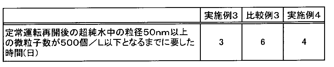
本発明は、特願2013-083233、特願2013-113027及び特願2013-153640に基づいており、その全体が引用により援用される。
Claims (19)
- 少なくともタンク、ポンプ、熱交換器、紫外線装置、イオン交換装置、及び第1の微粒子除去膜装置を備えた超純水製造システムに、殺菌水及びフラッシング水をそれぞれ通水して該超純水製造システムの殺菌洗浄及び殺菌洗浄後のフラッシング洗浄を行う超純水製造システムの洗浄方法であって、
該第1の微粒子除去膜装置と並列に第2の微粒子除去膜装置を設け、
下記(I-1)~(I-3)のいずれかの洗浄工程を行い、該洗浄工程後、該第2の微粒子除去膜装置に通水することなく、前記熱交換器、紫外線装置、イオン交換装置、及び第1の微粒子除去膜装置に通水して超純水の製造を行うことを特徴とする超純水製造システムの洗浄方法。
(I-1) 殺菌水及びフラッシング水の一部を前記第1の微粒子除去膜装置に供給して、該第1の微粒子除去膜装置の微粒子除去膜を透過させずに該第1の微粒子除去膜装置の給水側から濃縮水側へ排出し、残部を前記第2の微粒子除去膜装置に通水する。
(I-2) 殺菌水及びフラッシング水の全量を前記第2の微粒子除去膜装置に通水し、前記第1の微粒子除去膜装置の微粒子除去膜を予め殺菌処理した微粒子除去膜に交換する。
(I-3) 前記第1の微粒子除去膜装置の微粒子除去膜を配管と交換して、殺菌水及びフラッシング水の一部を該第1の微粒子除去膜装置に通水すると共に、残部を前記第2の微粒子除去膜装置に通水した後、該第1の微粒子除去膜装置の配管を予め殺菌処理した微粒子除去膜に交換する。 - 少なくともタンク、ポンプ、熱交換器、紫外線装置、イオン交換装置、及び第1の微粒子除去膜装置を備えた超純水製造システムに、殺菌水及びフラッシング水をそれぞれ通水して該超純水製造システムの殺菌洗浄及び殺菌洗浄後のフラッシング洗浄を行う超純水製造システムの洗浄方法であって、
該超純水製造システムの最終ポンプと該第1の微粒子除去膜装置との間に第2の微粒子除去膜装置を、該第2の微粒子除去膜装置をバイパスする通水が可能なように設け、
下記(II-1)~(II-3)のいずれかの洗浄工程を行い、該洗浄工程後、該第2の微粒子除去膜装置をバイパスして前記熱交換器、紫外線装置、イオン交換装置、及び第1の微粒子除去膜装置に通水して超純水の製造を行うことを特徴とする超純水製造システムの洗浄方法。
(II-1) 前記第1の微粒子除去膜装置をバイパスするバイパス配管を設け、殺菌水及びフラッシング水を前記第2の微粒子除去膜装置に通水し、該第2の微粒子除去膜装置を透過した水の一部を該第1の微粒子除去膜装置に供給して、該第1の微粒子除去膜装置の微粒子除去膜を透過させずに該第1の微粒子除去膜装置の給水側から濃縮水側へ排出し、残部を前記バイパス配管に通水する。
(II-2) 前記第1の微粒子除去膜装置をバイパスするバイパス配管を設け、殺菌水及びフラッシング水を前記第2の微粒子除去膜装置と該バイパス配管に通水し、該第1の微粒子除去膜装置の微粒子除去膜を予め殺菌処理した微粒子除去膜に交換する。
(II-3) 前記第1の微粒子除去膜装置の微粒子除去膜を配管と交換した後、殺菌水及びフラッシング水を前記第2の微粒子除去膜装置と該第1の微粒子除去膜装置に通水し、その後、該第1の微粒子除去膜装置の配管を予め殺菌処理した微粒子除去膜に交換する。 - 少なくともタンク、ポンプ、熱交換器、紫外線装置、イオン交換装置、及び第1の微粒子除去膜装置を備えた超純水製造システムに、殺菌水及びフラッシング水をそれぞれ通水して該超純水製造システムの殺菌洗浄及び殺菌洗浄後のフラッシング洗浄を行う超純水製造システムの洗浄方法であって、
該第1の微粒子除去膜装置の後段に第2の微粒子除去膜装置を、該第2の微粒子除去膜装置をバイパスする通水が可能なように設け、
下記(III-1)~(III-3)のいずれかの洗浄工程を行い、該洗浄工程後、該第2の微粒子除去膜装置をバイパスして前記熱交換器、紫外線装置、イオン交換装置、及び第1の微粒子除去膜装置に通水して超純水の製造を行うことを特徴とする超純水製造システムの洗浄方法。
(III-1) 前記第1の微粒子除去膜装置をバイパスするバイパスを設け、殺菌水及びフラッシング水の一部を該第1の微粒子除去膜装置に供給して、該第1の微粒子除去膜装置の微粒子除去膜を透過させずに該第1の微粒子除去膜装置の給水側から濃縮水側へ排出し、残部を前記バイパス配管に通水した後、前記第2の微粒子除去膜装置に通水する。
(III-2) 前記第1の微粒子除去膜装置をバイパスするバイパス配管を設け、殺菌水及びフラッシング水を該バイパス配管と前記第2の微粒子除去膜装置に通水し、前記第1の微粒子除去膜装置の微粒子除去膜を予め殺菌処理した微粒子除去膜に交換する。
(III-3) 前記第1の微粒子除去膜装置の微粒子除去膜を配管と交換した後、殺菌水及びフラッシング水を該第1の微粒子除去膜装置と前記第2の微粒子除去膜装置に通水し、その後、該第1の微粒子除去膜装置の配管を予め殺菌処理した微粒子除去膜に交換する。 - 請求項1ないし3のいずれか1項において、前記予め殺菌処理した微粒子除去膜が、酸化剤含有水、有機系溶液、及び熱水のいずれか1種以上の殺菌水による殺菌洗浄後、前記超純水製造システムに設置される前に、該微粒子除去膜内の該殺菌水を超純水で置換したものであることを特徴とする超純水製造システムの洗浄方法。
- 請求項4において、前記微粒子除去膜内の殺菌水を超純水で置換した後、6ヶ月以内に前記超純水製造システムに設置されることを特徴とする超純水製造システムの洗浄方法。
- 請求項1ないし5のいずれか1項において、前記殺菌洗浄及びフラッシング洗浄は、アルカリ洗浄及び/又は酸洗浄と組み合わせて行われることを特徴とする超純水製造システムの洗浄方法。
- 少なくともタンク、ポンプ、熱交換器、紫外線装置、イオン交換装置、及び第1の微粒子除去膜装置を備えた超純水製造システムと、該超純水製造システムで製造した超純水を水使用ポイントまで供給する供給配管と、該水使用ポイントの余剰水を超純水製造システムに返送する返送配管とを備えてなる超純水製造供給システムに、殺菌水及びフラッシング水をそれぞれ通水して該超純水製造供給システムの殺菌洗浄及び殺菌洗浄後のフラッシング洗浄を行う超純水製造供給システムの洗浄方法において、請求項1ないし6のいずれか1項に記載の超純水製造システムの洗浄方法により該超純水製造システムを洗浄し、前記洗浄工程で前記第2の微粒子除去膜装置を透過した殺菌水及びフラッシング水を該供給配管と返送配管に通水した後系外へ排出することを特徴とする超純水製造供給システムの洗浄方法。
- 少なくともタンク、ポンプ、熱交換器、紫外線装置、イオン交換装置、及び第1の微粒子除去膜装置を備えた超純水製造システムにおいて、
該第1の微粒子除去膜装置と並列に、第2の微粒子除去膜装置を設けたことを特徴とする超純水製造システム。 - 請求項8において、前記第1の微粒子除去膜装置のみの通水、前記第2の微粒子除去膜装置のみの通水、前記第1及び第2の微粒子除去膜装置の双方への通水の切り替えを行う流路切替手段が設けられていることを特徴とする超純水製造システム。
- 請求項9において、前記第2の微粒子除去膜装置を通過した水を前記第1の微粒子除去膜装置の通過水と合流する前に系外に排出することが可能な第1のブロー配管が設けられていることを特徴とする超純水製造システム。
- 少なくともタンク、ポンプ、熱交換器、紫外線装置、イオン交換装置、及び第1の微粒子除去膜装置を備えた超純水製造システムにおいて、
該超純水製造システムの最終ポンプと該第1の微粒子除去膜装置の間に、第2の微粒子除去膜装置を、該第2の微粒子除去膜装置をバイパスする通水が可能なように設けたことを特徴とする超純水製造システム。 - 請求項11において、前記第2の微粒子除去膜装置が前記イオン交換装置と並列に設けられ、該イオン交換装置のみの通水、該第2の微粒子除去膜装置のみの通水、該イオン交換装置及び該第2の微粒子除去膜装置の双方への通水の切り替えを行う流路切替手段が設けられていることを特徴とする超純水製造システム。
- 請求項12において、前記第2の微粒子除去膜装置を通過した水を前記イオン交換装置の通過水と合流する前に系外に排出することが可能な第1のブロー配管が設けられていることを特徴とする超純水製造システム。
- 少なくともタンク、ポンプ、熱交換器、紫外線装置、イオン交換装置、及び第1の微粒子除去膜装置を備えた超純水製造システムにおいて、
該第1の微粒子除去膜装置の後段に、第2の微粒子除去膜装置を、該第2の微粒子除去膜装置をバイパスする通水が可能なように設けたことを特徴とする超純水製造システム。 - 請求項14において、前記第2の微粒子除去膜装置は、前記第1の微粒子除去膜装置の後段の配管にバイパス配管を介して設けられており、該第1の微粒子除去膜装置の後段の配管のみの通水、該第2の微粒子除去膜装置のみの通水、該第1の微粒子除去膜装置の後段の配管及び該第2の微粒子除去膜装置の双方への通水の切り替えを行う流路切替手段が設けられていることを特徴とする超純水製造システム。
- 請求項15において、前記第2の微粒子除去膜装置を通過した水を、該第2の微粒子除去膜装置を通過した水が前記第1の微粒子除去膜装置の後段の配管に流入する前に系外に排出することが可能な第1のブロー配管が設けられていることを特徴とする超純水製造システム。
- 請求項15又は16において、前記第1の微粒子除去膜装置をバイパスする配管が設けられており、該第1の微粒子除去膜装置のみの通水、該第1の微粒子除去膜装置をバイパスする配管のみの通水、該第1の微粒子除去膜装置と該第1の微粒子除去膜装置をバイパスする配管の双方への通水の切り替えを行う流路切替手段が設けられていることを特徴とする超純水製造システム。
- 請求項8ないし17のいずれか1項に記載の超純水製造システムと、
該超純水製造システムで製造した超純水を水使用ポイントまで供給する供給配管と、
該水使用ポイントの余剰水を超純水製造システムに返送する返送配管と
を備えてなる超純水製造供給システム。 - 請求項18において、前記返送配管から分岐した第2のブロー配管が設けられていることを特徴とする超純水製造供給システム。
Priority Applications (5)
| Application Number | Priority Date | Filing Date | Title |
|---|---|---|---|
| JP2014535846A JP5733482B1 (ja) | 2013-07-24 | 2014-07-22 | 超純水製造供給システム及びその洗浄方法 |
| US14/906,441 US10138149B2 (en) | 2013-07-24 | 2014-07-22 | Ultrapure water production system, ultrapure water production feed system, and method for cleaning thereof |
| SG11201600470XA SG11201600470XA (en) | 2013-07-24 | 2014-07-22 | Ultrapure water production system, ultrapure water production feed system, and method for cleaning thereof |
| CN201480033352.5A CN105283422B (zh) | 2013-07-24 | 2014-07-22 | 超纯水制造系统、超纯水制造供给系统及其洗涤方法 |
| KR1020167001201A KR102027026B1 (ko) | 2013-07-24 | 2014-07-22 | 초순수 제조 시스템, 초순수 제조 공급 시스템 및 그 세정 방법 |
Applications Claiming Priority (2)
| Application Number | Priority Date | Filing Date | Title |
|---|---|---|---|
| JP2013153640 | 2013-07-24 | ||
| JP2013-153640 | 2013-07-24 |
Publications (1)
| Publication Number | Publication Date |
|---|---|
| WO2015012248A1 true WO2015012248A1 (ja) | 2015-01-29 |
Family
ID=52393283
Family Applications (1)
| Application Number | Title | Priority Date | Filing Date |
|---|---|---|---|
| PCT/JP2014/069282 Ceased WO2015012248A1 (ja) | 2013-07-24 | 2014-07-22 | 超純水製造システム、超純水製造供給システム及びその洗浄方法 |
Country Status (7)
| Country | Link |
|---|---|
| US (1) | US10138149B2 (ja) |
| JP (1) | JP5733482B1 (ja) |
| KR (1) | KR102027026B1 (ja) |
| CN (1) | CN105283422B (ja) |
| SG (1) | SG11201600470XA (ja) |
| TW (1) | TWI626221B (ja) |
| WO (1) | WO2015012248A1 (ja) |
Cited By (2)
| Publication number | Priority date | Publication date | Assignee | Title |
|---|---|---|---|---|
| JP2019025391A (ja) * | 2017-07-26 | 2019-02-21 | 栗田工業株式会社 | 超純水製造装置の運転方法及び超純水製造装置 |
| JP2023035084A (ja) * | 2021-08-31 | 2023-03-13 | オルガノ株式会社 | 水処理装置の立ち上げ方法 |
Families Citing this family (17)
| Publication number | Priority date | Publication date | Assignee | Title |
|---|---|---|---|---|
| CN105517960A (zh) * | 2013-10-04 | 2016-04-20 | 栗田工业株式会社 | 超纯水制造装置 |
| JP6107987B1 (ja) * | 2016-02-22 | 2017-04-05 | 栗田工業株式会社 | 超純水製造システムの洗浄方法 |
| DE102016004612A1 (de) * | 2016-04-19 | 2017-10-19 | Merck Patent Gmbh | Verfahren und Befüllungsvorrichtung zum Befüllen eines Transportbehälters mit einem Fluid |
| FR3052684A1 (fr) * | 2016-06-16 | 2017-12-22 | L'air Liquide Sa Pour L'etude Et L'exploitation Des Procedes Georges Claude | Appareil et procede de separation de co2 a basse temperature comprenant une etape de separation par permeation |
| JP6149992B1 (ja) * | 2016-09-14 | 2017-06-21 | 栗田工業株式会社 | 超純水製造装置 |
| WO2018074981A1 (en) * | 2016-10-20 | 2018-04-26 | Liquinex Group Pte. Ltd. | System and method for removing iron in liquid |
| JP6350706B1 (ja) * | 2017-03-30 | 2018-07-04 | 栗田工業株式会社 | 水質調整水製造装置 |
| JP6897263B2 (ja) * | 2017-04-14 | 2021-06-30 | 栗田工業株式会社 | 水質調整水の製造方法及び装置 |
| EP3618887B1 (en) * | 2017-05-05 | 2025-07-23 | Baxter International Inc. | A system and a method for producing microbiologically controlled fluid |
| JP6468384B1 (ja) * | 2018-03-14 | 2019-02-13 | 栗田工業株式会社 | 水処理装置 |
| CN109164768A (zh) * | 2018-08-31 | 2019-01-08 | 深圳市纯水号水处理科技有限公司 | 超纯水系统内过滤器的旁通系统安全隐患智能化处理方法 |
| JP7171386B2 (ja) * | 2018-11-22 | 2022-11-15 | 野村マイクロ・サイエンス株式会社 | 超純水製造装置の立ち上げ方法及び超純水製造装置 |
| CN111377527A (zh) | 2018-12-31 | 2020-07-07 | 中国石油化工股份有限公司 | 一种高含盐有机废水的处理方法 |
| EP3946766A1 (en) * | 2019-04-05 | 2022-02-09 | Ecolab USA Inc. | Clean-in-place using ultrasoft water |
| JP7124175B1 (ja) * | 2021-06-16 | 2022-08-23 | 野村マイクロ・サイエンス株式会社 | 液体回収システム、液体供給システム、及び圧力調整方法 |
| KR102458920B1 (ko) | 2022-02-21 | 2022-10-25 | 삼성전자주식회사 | 유체 공급 장치 |
| KR102549174B1 (ko) * | 2022-05-19 | 2023-06-30 | 삼성전자주식회사 | 한외여과막 모듈의 세정 방법 및 이를 이용한 초순수 제조 시스템의 관리 방법 |
Citations (4)
| Publication number | Priority date | Publication date | Assignee | Title |
|---|---|---|---|---|
| JPS6214986A (ja) * | 1985-07-13 | 1987-01-23 | Kitazawa Valve:Kk | 超純水製造装置 |
| JP2004122020A (ja) * | 2002-10-03 | 2004-04-22 | Japan Organo Co Ltd | 超純水製造装置及び該装置における超純水製造供給システムの洗浄方法 |
| JP2005224656A (ja) * | 2004-02-10 | 2005-08-25 | Japan Organo Co Ltd | 超純水製造供給装置 |
| JP2011161418A (ja) * | 2010-02-15 | 2011-08-25 | Kurita Water Ind Ltd | 超純水製造システムの洗浄方法 |
Family Cites Families (15)
| Publication number | Priority date | Publication date | Assignee | Title |
|---|---|---|---|---|
| US4708790A (en) * | 1984-06-04 | 1987-11-24 | Champion International Corporation | Ultrafiltration system with regeneration control |
| US5518624A (en) * | 1994-05-06 | 1996-05-21 | Illinois Water Treatment, Inc. | Ultra pure water filtration |
| US6328896B1 (en) * | 1998-04-24 | 2001-12-11 | United States Filter Corporation | Process for removing strong oxidizing agents from liquids |
| JP3620577B2 (ja) | 1999-05-14 | 2005-02-16 | 栗田工業株式会社 | 超純水製造システムの洗浄方法 |
| JP3480458B2 (ja) | 2001-08-10 | 2003-12-22 | 栗田工業株式会社 | 殺菌方法 |
| JP2003181247A (ja) * | 2001-12-17 | 2003-07-02 | Nitto Denko Corp | スパイラル型膜エレメントを備えた処理システムおよびその運転方法 |
| JP4228732B2 (ja) | 2003-03-14 | 2009-02-25 | 栗田工業株式会社 | 超純水製造システム |
| US20050067341A1 (en) * | 2003-09-25 | 2005-03-31 | Green Dennis H. | Continuous production membrane water treatment plant and method for operating same |
| US20080093277A1 (en) * | 2006-06-13 | 2008-04-24 | John Armour | Cadence detection in a sequence of video fields |
| KR101098068B1 (ko) * | 2006-10-31 | 2011-12-26 | 쿠리타 고교 가부시키가이샤 | 초순수의 고순도화 방법 및 장치 |
| KR101407831B1 (ko) | 2007-03-30 | 2014-06-17 | 쿠리타 고교 가부시키가이샤 | 초순수 제조 시스템의 세정 살균 방법 |
| JP5120070B2 (ja) * | 2008-05-29 | 2013-01-16 | 三浦工業株式会社 | 水処理装置 |
| US20130313191A1 (en) | 2009-05-14 | 2013-11-28 | Omni Water Solutions, Inc. | Water treatment systems and methods |
| CN201423250Y (zh) * | 2009-06-17 | 2010-03-17 | 浙江玉泉环境工程有限公司 | 超滤膜自清洗装置 |
| CN102527244B (zh) | 2012-01-10 | 2014-06-25 | 蓝星环境工程有限公司 | 一种反渗透膜的清洗方法 |
-
2014
- 2014-07-22 SG SG11201600470XA patent/SG11201600470XA/en unknown
- 2014-07-22 CN CN201480033352.5A patent/CN105283422B/zh active Active
- 2014-07-22 KR KR1020167001201A patent/KR102027026B1/ko active Active
- 2014-07-22 WO PCT/JP2014/069282 patent/WO2015012248A1/ja not_active Ceased
- 2014-07-22 JP JP2014535846A patent/JP5733482B1/ja active Active
- 2014-07-22 US US14/906,441 patent/US10138149B2/en active Active
- 2014-07-24 TW TW103125298A patent/TWI626221B/zh active
Patent Citations (4)
| Publication number | Priority date | Publication date | Assignee | Title |
|---|---|---|---|---|
| JPS6214986A (ja) * | 1985-07-13 | 1987-01-23 | Kitazawa Valve:Kk | 超純水製造装置 |
| JP2004122020A (ja) * | 2002-10-03 | 2004-04-22 | Japan Organo Co Ltd | 超純水製造装置及び該装置における超純水製造供給システムの洗浄方法 |
| JP2005224656A (ja) * | 2004-02-10 | 2005-08-25 | Japan Organo Co Ltd | 超純水製造供給装置 |
| JP2011161418A (ja) * | 2010-02-15 | 2011-08-25 | Kurita Water Ind Ltd | 超純水製造システムの洗浄方法 |
Cited By (3)
| Publication number | Priority date | Publication date | Assignee | Title |
|---|---|---|---|---|
| JP2019025391A (ja) * | 2017-07-26 | 2019-02-21 | 栗田工業株式会社 | 超純水製造装置の運転方法及び超純水製造装置 |
| JP2023035084A (ja) * | 2021-08-31 | 2023-03-13 | オルガノ株式会社 | 水処理装置の立ち上げ方法 |
| JP7645747B2 (ja) | 2021-08-31 | 2025-03-14 | オルガノ株式会社 | 水処理装置の立ち上げ方法 |
Also Published As
| Publication number | Publication date |
|---|---|
| KR20160034293A (ko) | 2016-03-29 |
| TW201520175A (zh) | 2015-06-01 |
| US20160159672A1 (en) | 2016-06-09 |
| CN105283422B (zh) | 2017-09-22 |
| CN105283422A (zh) | 2016-01-27 |
| KR102027026B1 (ko) | 2019-09-30 |
| JPWO2015012248A1 (ja) | 2017-03-02 |
| US10138149B2 (en) | 2018-11-27 |
| SG11201600470XA (en) | 2016-02-26 |
| TWI626221B (zh) | 2018-06-11 |
| JP5733482B1 (ja) | 2015-06-10 |
Similar Documents
| Publication | Publication Date | Title |
|---|---|---|
| JP5733482B1 (ja) | 超純水製造供給システム及びその洗浄方法 | |
| JP6225487B2 (ja) | 超純水製造システム及び超純水製造供給システム | |
| JP5287713B2 (ja) | 超純水製造システムの洗浄殺菌方法 | |
| JP4228732B2 (ja) | 超純水製造システム | |
| CN112770825B (zh) | 超纯水制造装置的启动方法以及超纯水制造装置 | |
| WO2018051551A1 (ja) | 超純水製造装置 | |
| KR20190005843A (ko) | 초순수 제조 장치의 기동 방법 | |
| Ito et al. | Efficient and simultaneous recovery of ammonia and carbon from municipal wastewater by the combination of direct membrane filtration (DMF) and the use of a membrane contactor | |
| JP3620577B2 (ja) | 超純水製造システムの洗浄方法 | |
| JP6107987B1 (ja) | 超純水製造システムの洗浄方法 | |
| CN205275367U (zh) | 一种柴油发电机用冷却循环水系统 | |
| JP6428017B2 (ja) | 水処理装置及び水処理設備の洗浄方法 | |
| JP7645747B2 (ja) | 水処理装置の立ち上げ方法 | |
| JP5434752B2 (ja) | 濾過装置及びその運転方法 | |
| JP7838279B2 (ja) | 超純水製造設備 | |
| JP2002192162A (ja) | 超純水製造システムの洗浄殺菌方法 | |
| JP2007125526A (ja) | 逆浸透膜分離装置の運転方法 | |
| JP2025168955A (ja) | 超純水製造装置の立ち上げ時の洗浄方法 | |
| JP2004026987A (ja) | 超純水製造システムの洗浄方法 | |
| JP2007237115A (ja) | 膜分離装置及びその洗浄方法 | |
| JP2002052324A (ja) | 超純水製造システムの洗浄方法 |
Legal Events
| Date | Code | Title | Description |
|---|---|---|---|
| WWE | Wipo information: entry into national phase |
Ref document number: 201480033352.5 Country of ref document: CN |
|
| ENP | Entry into the national phase |
Ref document number: 2014535846 Country of ref document: JP Kind code of ref document: A |
|
| 121 | Ep: the epo has been informed by wipo that ep was designated in this application |
Ref document number: 14830279 Country of ref document: EP Kind code of ref document: A1 |
|
| ENP | Entry into the national phase |
Ref document number: 20167001201 Country of ref document: KR Kind code of ref document: A |
|
| WWE | Wipo information: entry into national phase |
Ref document number: 14906441 Country of ref document: US |
|
| NENP | Non-entry into the national phase |
Ref country code: DE |
|
| 122 | Ep: pct application non-entry in european phase |
Ref document number: 14830279 Country of ref document: EP Kind code of ref document: A1 |