WO2015004888A1 - 空気入りタイヤ - Google Patents
空気入りタイヤ Download PDFInfo
- Publication number
- WO2015004888A1 WO2015004888A1 PCT/JP2014/003553 JP2014003553W WO2015004888A1 WO 2015004888 A1 WO2015004888 A1 WO 2015004888A1 JP 2014003553 W JP2014003553 W JP 2014003553W WO 2015004888 A1 WO2015004888 A1 WO 2015004888A1
- Authority
- WO
- WIPO (PCT)
- Prior art keywords
- width direction
- tire
- narrow groove
- groove
- tire width
- Prior art date
Links
Images

Classifications
-
- B—PERFORMING OPERATIONS; TRANSPORTING
- B60—VEHICLES IN GENERAL
- B60C—VEHICLE TYRES; TYRE INFLATION; TYRE CHANGING; CONNECTING VALVES TO INFLATABLE ELASTIC BODIES IN GENERAL; DEVICES OR ARRANGEMENTS RELATED TO TYRES
- B60C11/00—Tyre tread bands; Tread patterns; Anti-skid inserts
- B60C11/03—Tread patterns
- B60C11/0327—Tread patterns characterised by special properties of the tread pattern
-
- B—PERFORMING OPERATIONS; TRANSPORTING
- B60—VEHICLES IN GENERAL
- B60C—VEHICLE TYRES; TYRE INFLATION; TYRE CHANGING; CONNECTING VALVES TO INFLATABLE ELASTIC BODIES IN GENERAL; DEVICES OR ARRANGEMENTS RELATED TO TYRES
- B60C11/00—Tyre tread bands; Tread patterns; Anti-skid inserts
- B60C11/03—Tread patterns
- B60C11/0306—Patterns comprising block rows or discontinuous ribs
-
- B—PERFORMING OPERATIONS; TRANSPORTING
- B60—VEHICLES IN GENERAL
- B60C—VEHICLE TYRES; TYRE INFLATION; TYRE CHANGING; CONNECTING VALVES TO INFLATABLE ELASTIC BODIES IN GENERAL; DEVICES OR ARRANGEMENTS RELATED TO TYRES
- B60C11/00—Tyre tread bands; Tread patterns; Anti-skid inserts
- B60C11/03—Tread patterns
- B60C11/12—Tread patterns characterised by the use of narrow slits or incisions, e.g. sipes
- B60C11/1236—Tread patterns characterised by the use of narrow slits or incisions, e.g. sipes with special arrangements in the tread pattern
-
- B—PERFORMING OPERATIONS; TRANSPORTING
- B60—VEHICLES IN GENERAL
- B60C—VEHICLE TYRES; TYRE INFLATION; TYRE CHANGING; CONNECTING VALVES TO INFLATABLE ELASTIC BODIES IN GENERAL; DEVICES OR ARRANGEMENTS RELATED TO TYRES
- B60C11/00—Tyre tread bands; Tread patterns; Anti-skid inserts
- B60C11/03—Tread patterns
- B60C11/0327—Tread patterns characterised by special properties of the tread pattern
- B60C2011/0334—Stiffness
-
- B—PERFORMING OPERATIONS; TRANSPORTING
- B60—VEHICLES IN GENERAL
- B60C—VEHICLE TYRES; TYRE INFLATION; TYRE CHANGING; CONNECTING VALVES TO INFLATABLE ELASTIC BODIES IN GENERAL; DEVICES OR ARRANGEMENTS RELATED TO TYRES
- B60C11/00—Tyre tread bands; Tread patterns; Anti-skid inserts
- B60C11/03—Tread patterns
- B60C2011/0337—Tread patterns characterised by particular design features of the pattern
- B60C2011/0339—Grooves
- B60C2011/0341—Circumferential grooves
- B60C2011/0344—Circumferential grooves provided at the equatorial plane
-
- B—PERFORMING OPERATIONS; TRANSPORTING
- B60—VEHICLES IN GENERAL
- B60C—VEHICLE TYRES; TYRE INFLATION; TYRE CHANGING; CONNECTING VALVES TO INFLATABLE ELASTIC BODIES IN GENERAL; DEVICES OR ARRANGEMENTS RELATED TO TYRES
- B60C11/00—Tyre tread bands; Tread patterns; Anti-skid inserts
- B60C11/03—Tread patterns
- B60C2011/0337—Tread patterns characterised by particular design features of the pattern
- B60C2011/0339—Grooves
- B60C2011/0358—Lateral grooves, i.e. having an angle of 45 to 90 degees to the equatorial plane
- B60C2011/036—Narrow grooves, i.e. having a width of less than 3 mm
-
- B—PERFORMING OPERATIONS; TRANSPORTING
- B60—VEHICLES IN GENERAL
- B60C—VEHICLE TYRES; TYRE INFLATION; TYRE CHANGING; CONNECTING VALVES TO INFLATABLE ELASTIC BODIES IN GENERAL; DEVICES OR ARRANGEMENTS RELATED TO TYRES
- B60C11/00—Tyre tread bands; Tread patterns; Anti-skid inserts
- B60C11/03—Tread patterns
- B60C2011/0337—Tread patterns characterised by particular design features of the pattern
- B60C2011/0339—Grooves
- B60C2011/0358—Lateral grooves, i.e. having an angle of 45 to 90 degees to the equatorial plane
- B60C2011/0365—Lateral grooves, i.e. having an angle of 45 to 90 degees to the equatorial plane characterised by width
-
- B—PERFORMING OPERATIONS; TRANSPORTING
- B60—VEHICLES IN GENERAL
- B60C—VEHICLE TYRES; TYRE INFLATION; TYRE CHANGING; CONNECTING VALVES TO INFLATABLE ELASTIC BODIES IN GENERAL; DEVICES OR ARRANGEMENTS RELATED TO TYRES
- B60C11/00—Tyre tread bands; Tread patterns; Anti-skid inserts
- B60C11/03—Tread patterns
- B60C2011/0337—Tread patterns characterised by particular design features of the pattern
- B60C2011/0339—Grooves
- B60C2011/0358—Lateral grooves, i.e. having an angle of 45 to 90 degees to the equatorial plane
- B60C2011/0367—Lateral grooves, i.e. having an angle of 45 to 90 degees to the equatorial plane characterised by depth
-
- B—PERFORMING OPERATIONS; TRANSPORTING
- B60—VEHICLES IN GENERAL
- B60C—VEHICLE TYRES; TYRE INFLATION; TYRE CHANGING; CONNECTING VALVES TO INFLATABLE ELASTIC BODIES IN GENERAL; DEVICES OR ARRANGEMENTS RELATED TO TYRES
- B60C11/00—Tyre tread bands; Tread patterns; Anti-skid inserts
- B60C11/03—Tread patterns
- B60C2011/0337—Tread patterns characterised by particular design features of the pattern
- B60C2011/0339—Grooves
- B60C2011/0358—Lateral grooves, i.e. having an angle of 45 to 90 degees to the equatorial plane
- B60C2011/0372—Lateral grooves, i.e. having an angle of 45 to 90 degees to the equatorial plane with particular inclination angles
-
- B—PERFORMING OPERATIONS; TRANSPORTING
- B60—VEHICLES IN GENERAL
- B60C—VEHICLE TYRES; TYRE INFLATION; TYRE CHANGING; CONNECTING VALVES TO INFLATABLE ELASTIC BODIES IN GENERAL; DEVICES OR ARRANGEMENTS RELATED TO TYRES
- B60C11/00—Tyre tread bands; Tread patterns; Anti-skid inserts
- B60C11/03—Tread patterns
- B60C2011/0337—Tread patterns characterised by particular design features of the pattern
- B60C2011/0339—Grooves
- B60C2011/0381—Blind or isolated grooves
- B60C2011/0383—Blind or isolated grooves at the centre of the tread
-
- B—PERFORMING OPERATIONS; TRANSPORTING
- B60—VEHICLES IN GENERAL
- B60C—VEHICLE TYRES; TYRE INFLATION; TYRE CHANGING; CONNECTING VALVES TO INFLATABLE ELASTIC BODIES IN GENERAL; DEVICES OR ARRANGEMENTS RELATED TO TYRES
- B60C11/00—Tyre tread bands; Tread patterns; Anti-skid inserts
- B60C11/03—Tread patterns
- B60C2011/0337—Tread patterns characterised by particular design features of the pattern
- B60C2011/0386—Continuous ribs
- B60C2011/0393—Narrow ribs, i.e. having a rib width of less than 8 mm
- B60C2011/0395—Narrow ribs, i.e. having a rib width of less than 8 mm for linking shoulder blocks
-
- B—PERFORMING OPERATIONS; TRANSPORTING
- B60—VEHICLES IN GENERAL
- B60C—VEHICLE TYRES; TYRE INFLATION; TYRE CHANGING; CONNECTING VALVES TO INFLATABLE ELASTIC BODIES IN GENERAL; DEVICES OR ARRANGEMENTS RELATED TO TYRES
- B60C11/00—Tyre tread bands; Tread patterns; Anti-skid inserts
- B60C11/03—Tread patterns
- B60C11/12—Tread patterns characterised by the use of narrow slits or incisions, e.g. sipes
- B60C11/1204—Tread patterns characterised by the use of narrow slits or incisions, e.g. sipes with special shape of the sipe
- B60C2011/1209—Tread patterns characterised by the use of narrow slits or incisions, e.g. sipes with special shape of the sipe straight at the tread surface
Definitions
- the present invention relates to a pneumatic tire having improved dry performance while ensuring wet performance.
- a plurality of main grooves extending in the tire circumferential direction are provided on the tread surface of the tire.
- an object of the present invention is to provide a pneumatic tire having improved dry performance while ensuring wet performance.
- the pneumatic tire of the present invention has one central main groove extending in the tire circumferential direction on the tread portion tread surface, and the central main groove interposed therebetween.
- Four land portions are defined by the side main grooves extending in the tire circumferential direction provided on both sides, and the central land portion rows sandwiched between the central main grooves and the side main grooves are Opening in the central main groove, opening in the side main groove, at least one first narrow groove having an extension length a in the tire width direction and an angle ⁇ with respect to the tire width direction;
- a lateral width that is at least one second narrow groove having an extension length b in the tire width direction and an angle ⁇ with respect to the tire width direction is located outside the lateral main groove in the tire width direction.
- Forming at least one third narrow groove having a degree of ⁇ , the length a extending in the tire width direction of the first narrow groove, the length b extending in the tire width direction of the second narrow groove, and the first An angle ⁇ formed with respect to the tire width direction of the narrow groove, an angle ⁇ formed with respect to the tire width direction of the second narrow groove, and an angle ⁇ formed with respect to the tire width direction of the third narrow groove are as follows: It is characterized by satisfying a ⁇ b and ⁇ ⁇ ⁇ .
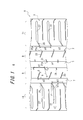
- FIG. 2 is a partial development view showing a tread pattern of a pneumatic tire as an example.
- the tire 1 of the present embodiment includes a pair of bead portions, a pair of sidewall portions connected to the outside in the tire radial direction of the bead portion, and a tread portion straddling the sidewall portions, Between the bead cores embedded in the bead portion, a carcass extending in a toroid shape over these portions, and a belt composed of a plurality of belt layers are disposed on the outer side in the tire radial direction of the crown portion of the carcass.
- FIG. 1 is a development view showing a part of a tread portion 3 of a pneumatic tire (hereinafter also referred to as a tire) 1 according to an embodiment of the present invention.
- the tread portion 3 has one central main groove 5 that continuously extends linearly along the tire circumferential direction on the tire equatorial plane E, and the tire circumferential direction provided on both sides of the central main groove 5.
- 2 side main grooves 7 extending continuously in a straight line along two central land portion rows 9 and two rows of side land portions located outside the central land portion row 9 in the tire width direction.
- a row 11 is partitioned.
- the central main groove 5 and the side main grooves 7 do not necessarily extend linearly along the tire circumferential direction, and may extend in a zigzag shape or while being curved.
- the central land portion row 9 is formed with at least one first narrow groove 21 opened in the central main groove 5 and at least one second narrow groove 23 opened in the side main groove 7.
- a plurality of first fine grooves 21 are arranged at equal intervals along the tire circumferential direction at intervals p1, and the second fine grooves 23 are equally spaced at intervals p2 along the tire circumferential direction. Arranged, p1 and p2 are equal.
- the first narrow grooves 21 and the second narrow grooves 23 are arranged in a staggered manner so as to be alternated in the tire circumferential direction.
- the interval between the narrow grooves along the tire circumferential direction is not necessarily constant, and can be arranged at an arbitrary interval.
- the side land portion row 11 is formed with at least one third narrow groove 25 that opens to the side main groove 7.
- a plurality of third narrow grooves 25 are arranged at equal intervals in the tire circumferential direction at an interval p3, and p3 is equal to p1 and p2.
- the length a extending in the tire width direction of the first narrow groove 21 and the length b extending in the tire width direction of the second narrow groove 23 satisfy the relationship of a ⁇ b.
- the angle ⁇ of the first narrow groove 21 with respect to the tire width direction, the angle ⁇ of the second narrow groove 23 with respect to the tire width direction, and the angle ⁇ with respect to the tire width direction of the third narrow groove 25 satisfy the relationship of ⁇ ⁇ ⁇ . Yes.
- an extension groove 27 extending outward in the tire width direction at an angle different from that of the third narrow groove 25 is formed continuously to the third narrow groove 25, but the present invention is not limited to this.
- the extending length c of the third narrow groove 25 in the tire width direction indicates the extending length in the tire width direction of the narrow groove that holds the angle ⁇ with respect to the tire width direction.
- a narrow groove that does not open in the side main groove 7 is disposed between the adjacent extension grooves 27, but this narrow groove may not be provided as in the example shown in FIG.
- the tread pattern of the tire 1 has a point-symmetric shape with a point on the tire equatorial plane E located at the center of the central main groove 5 as a symmetric point, but the present invention is not limited to this.
- the first narrow groove 21, the second narrow groove 23, and the third narrow groove 25 absorb water between the tread surface and the road surface in each land section row, While discharging efficiently through the central main groove 5 and the side main grooves 7 communicated with each narrow groove, the steering film stability and braking performance (wet performance) are ensured by the water film removal effect by each narrow groove. . Moreover, the occurrence of hydroplaning can be suppressed by ensuring drainage.
- the angle of the first narrow groove 21 with respect to the tire width direction is small, the contact pressure of the land edge adjacent to the groove (hereinafter also referred to as edge pressure) increases, and the tread surface near the narrow groove Since the effect of removing the water film between the road surfaces becomes high, even if the length of the first narrow groove 21 extending in the tire width direction is shortened, it is possible to suppress a decrease in drainage. Further, since the second narrow groove 23 has a long extending length in the tire width direction, it can exhibit high drainage.
- the central land portion row 9 is a rib-like land portion continuous in the tire circumferential direction, as compared to a block-like land portion in which the land portion row is divided by a narrow groove extending in the tire width direction. It is difficult to deform and has high rigidity. Moreover, in addition to the length a extending in the tire width direction of the first narrow groove 21 being short and the angle ⁇ with respect to the tire width direction being small, the first narrow grooves 21 and the second narrow grooves 23 are alternately arranged. Thereby, the rigidity of the central land portion row 9 can be increased, and the dry performance can be further improved.
- the length a of the first narrow groove 21 extends in the tire width direction
- the length b of the second narrow groove extends in the tire width direction
- the third narrow groove 25 The tire width direction extending length c preferably satisfies the following formula a ⁇ c ⁇ b. According to this, the effect of improving the dry performance while securing the wet performance is ensured by the arrangement of appropriate narrow grooves. Can be increased.
- the depth of the first narrow groove 21 is 50% to 100% of the depth of the central main groove, and the depth of the second and third narrow grooves.
- the depth is preferably 50% to 100% of the depth of the side main groove.
- the depth of the first narrow groove 21 exceeds 100% of the depth of the central main groove, or the second and third narrow grooves. If the depth is more than 100% of the depth of the side main groove, the rigidity of the land portion is lowered, and there is a possibility that the effect of improving the dry performance cannot be sufficiently obtained.
- the angle ⁇ formed with respect to the tire width direction of the first narrow groove 21 is 15 ° or less. Sufficient performance can be secured. If the angle ⁇ is greater than 15 °, the water film removal effect may be reduced due to a decrease in edge pressure, and sufficient wet performance may not be ensured.
- the length b extending in the tire width direction of the second narrow groove 23 is preferably 30% to 90% of the width in the tire width direction of the central land portion row 9. According to this, the drainage performance of the second narrow groove 23 is appropriately secured to sufficiently secure the wet performance, while the rigidity of the central land portion row 9 is prevented from being lowered and the dry performance is more reliably improved. be able to. If the tire width direction extending length b is less than 30% of the tire land width direction of the central land portion row 9, sufficient drainage performance may not be obtained and sufficient wet performance may not be secured. If it exceeds 90% There is a possibility that the rigidity of the central land portion row 9 is lowered and the effect of improving the dry performance cannot be sufficiently obtained.
- the angle ⁇ formed with respect to the tire width direction of the second narrow groove 23 is 15 ° to 30 °. While ensuring the drainage performance of the grooves 23 and sufficiently ensuring the wet performance, it is possible to more reliably improve the dry performance by preventing the rigidity of the central land row 9 from being lowered. If this angle ⁇ is less than 15 °, the effect of improving the braking performance on the dry road surface may not be obtained sufficiently. If it exceeds 30 °, the rigidity of the central land section row 9 decreases and the dry road surface There is a risk that the effect of improving the steering stability cannot be sufficiently obtained.
- the length c extending in the tire width direction of the third narrow groove 25 is 5% to 30% of the width in the tire width direction of the side land portion row 11.
- the drainage performance of the third narrow groove is appropriately secured to ensure sufficient wet performance, but the rigidity of the side land portion row 11 is prevented and the dry performance is more reliably improved. can do.
- the length c extending in the tire width direction of the third narrow groove 25 is less than 5% of the width in the tire width direction of the side land portion row 11, there is a possibility that sufficient drainage cannot be obtained and sufficient wet performance cannot be secured. If it exceeds 30%, the rigidity of the central land section row 9 is lowered, and there is a possibility that the effect of improving the dry performance cannot be obtained sufficiently.
- the angle ⁇ formed by the third narrow groove 25 with respect to the tire width direction is 30 ° to 50 °. While ensuring the drainage performance of the grooves and sufficiently ensuring the wet performance, the rigidity of the side land portion row 11 can be prevented from being lowered and the dry performance can be more reliably improved. If the angle ⁇ formed with respect to the tire width direction of the third narrow groove 25 is less than 30 °, the effect of improving the braking performance on a dry road surface may not be sufficiently obtained. There is a possibility that the rigidity of the land portion row 9 is lowered and the effect of improving the steering stability on the dry road surface cannot be sufficiently obtained.
- the first narrow groove 21, the second narrow groove 23, and the third narrow groove 25 preferably have a width of 0.2 mm to 3.0 mm.
- the width of the first narrow groove 21, the second narrow groove 23, and the third narrow groove 25 is less than 0.2 mm, sufficient drainage performance may not be obtained, and sufficient wet performance may not be ensured, exceeding 3.0 mm.
- column falls, and there exists a possibility that the improvement effect of dry performance may not fully be acquired.
- the inclination direction of the tire 25 with respect to the tire width direction is the same when viewed from the openings 21a, 23a, 25a to the central main groove 5 or the side main grooves 25. According to this, the water between the tread surface and the road surface absorbed by each narrow groove is discharged into the central main groove 5 or the side main groove 7 in the same direction, thereby efficiently draining water and improving the wet performance. Can be secured.
- Comparative Example 1 has the tread pattern shown in FIG. 2A
- Comparative Example 2 has the tread pattern shown in FIG. 2B
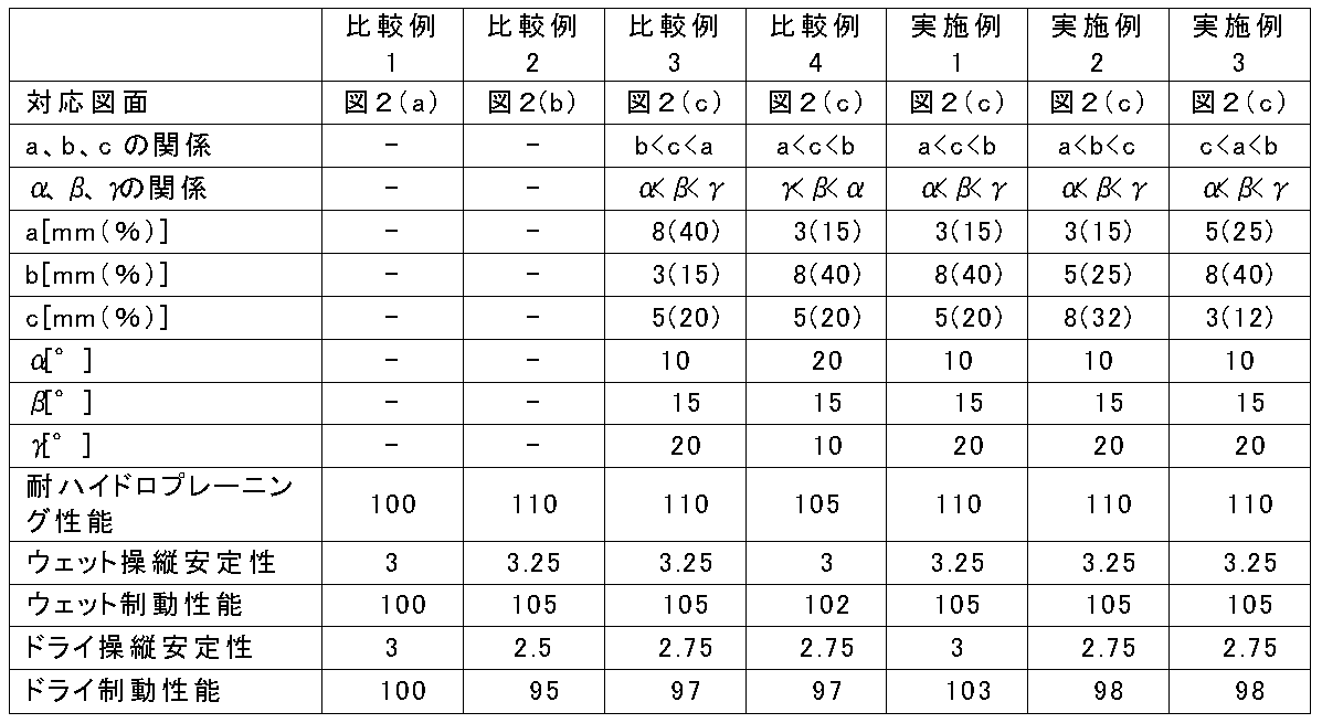
- Comparative Examples 3 and 4 and Examples 1 to 3 are shown in FIG. It has a tread pattern shown in c).
- the tires of Comparative Examples 1 to 4 and Examples 1 to 3 have the same structure except for the tread pattern.
- the tire 100 of Comparative Example 1 having the tread pattern shown in FIG. 2A has two rows of central land by the central main groove 105 and the side main grooves 107 continuously extending over the entire circumference in the tire circumferential direction.
- the partial row 109 and the two lateral land portion rows 111 are formed, and the central land portion row 109 and the lateral land portion row 111 are not formed with a narrow groove or the like.
- the tire 200 of Comparative Example 2 having the tread pattern shown in FIG. 2B has two rows of central land portions by the central main groove 205 and the side main grooves 207 extending continuously over the entire circumference in the tire circumferential direction.
- a row 209 and two lateral land portion rows 211 are formed.
- the narrow land 209 crossing the central land portion row 209 and the narrow groove 225 crossing the side land portion row 211, the central land portion row 209 and the side land portion row 211 have a plurality of block land portions.
- the land portion row arranged in the tire circumferential direction is formed.
- the tire 300 having the tread pattern shown in FIG. 2C has two central land portion rows 309 and two rows by a central main groove 305 and a side main groove 307 continuously extending over the entire circumference in the tire circumferential direction.
- the side land portion row 311 is formed.
- the first narrow grooves 321 and the second narrow grooves 323 are alternately formed in the tire circumferential direction, and in the lateral land portion row 311, the third narrow grooves 325 are formed.
- the tire width direction extending length a of the first narrow groove 321, the tire width direction extending length b of the second narrow groove 323, and the tire width of the third narrow groove 325 Similar to the embodiment of the present invention described above, the tire width direction extending length a of the first narrow groove 321, the tire width direction extending length b of the second narrow groove 323, and the tire width of the third narrow groove 325.
- Table 1 shows the respective values.
- the values of a, b, and c are shown as an absolute value (mm) and a ratio (%) with respect to the width of the land portion row, respectively.
- ⁇ Hydroplaning resistance> For vehicles equipped with tires, the hydroplaning limit speed when passing straight on a wet road surface of 10 mm in water depth was evaluated. The evaluation results are expressed as an index with Comparative Example 1 being 100, and the larger the value, the better the hydroplaning performance. The results are shown in Table 1.
- ⁇ Wet handling stability> For each vehicle equipped with tires, wet steering stability was evaluated by comprehensively evaluating the straightness and cornering performance of a vehicle on a wet road in various driving modes with a professional test driver. The evaluation results are indicated by an index with Comparative Example 1 set to 3, and the larger the value, the better the wet steering stability. The results are shown in Table 1.
Landscapes
- Engineering & Computer Science (AREA)
- Mechanical Engineering (AREA)
- Tires In General (AREA)
Abstract
Description
本実施形態のタイヤ1は、図示はしないが、慣例に従い、一対のビード部と、ビード部のタイヤ径方向外側に連なる一対のサイドウォール部と、サイドウォール部間に跨るトレッド部とからなり、ビード部に埋設されたビードコア間で、これら各部に亘ってトロイド状に延在するカーカスと、カーカスのクラウン部のタイヤ径方向外側に複数のベルト層からなるベルトが配設される。
各タイヤを装着した車両につき、水深10mmのウェット路面を直進で通過する際のハイドロプレーニング発生限界速度を評価した。評価結果は比較例1を100とした指数表示とし、数値が大きいほど耐ハイドロプレーニング性能が優れていることを示す。結果を表1に示す。
<ウェット操縦安定性>
各タイヤを装着した車両につき、湿潤路面のテストコースを各種走行モードで走行したときの直進性及びコーナリング性をプロのテストドライバーにより総合的にフィーリング評価することによりウェット操縦安定性を評価した。評価結果は、比較例1を3とした指数表示とし、数値が大きいほどウェット操縦安定性に優れることを示す。結果を表1に示す。
<ウェット制動性能>
各タイヤを装着した車両につき、ウェット路面を、初速100km/hで走行し、フルブレーキ時の停止距離(mm)の逆数を指数評価した。評価結果は、比較例1を100とした指数表示とし、数値が大きいほどウェット制動性能が優れていることを示す。結果を表1に示す。
<ドライ操縦安定性>
各タイヤを装着した車両につき、乾燥路面のテストコースを各種走行モードで走行したときの直進性及びコーナリング性をプロのテストドライバーにより総合的にフィーリング評価することによりドライ操縦安定性を評価した。評価結果は、比較例1を3とした指数表示とし、数値が大きいほどドライ操縦安定性に優れることを示す。結果を表1に示す。
<ドライ制動性能>
(各タイヤを装着した車両につき、乾燥路面で100Km/hで走行し、フルブレーキ時の停止距離(mm)の逆数を指数評価した。評価結果は、比較例1を3とした指数表示とし、数値が大きいほどドライ制動性能が優れていることを示す。結果を表1に示す。
3 トレッド部
5 中央主溝
7 側方主溝
9 中央陸部列
11 側方陸部列
21 第1細溝
21a 第1細溝の中央主溝への開口部
23 第2細溝
23a 第2細溝の中央主溝への開口部
25 第3細溝
25a 第3細溝の中央主溝への開口部
Claims (12)
- トレッド部踏面に、タイヤ周方向に延びる1本の中央主溝と、該中央主溝を挟んで両側に設けられたタイヤ周方向に延びる側方主溝とによって4列の陸部列を区画形成し、
前記中央主溝と前記側方主溝の間に挟まれた中央陸部列に、前記中央主溝に開口し、タイヤ幅方向延在長さがaでありタイヤ幅方向に対してなす角度がαである少なくとも1本の第1細溝、及び、前記側方主溝に開口し、タイヤ幅方向延在長さがbでありタイヤ幅方向に対してなす角度がβである少なくとも1本の第2細溝を形成し、
前記側方主溝のタイヤ幅方向外側に位置する側方陸部列に、前記側方主溝に開口し、タイヤ幅方向延在長さがcでありタイヤ幅方向に対してなす角度がγである少なくとも1本の第3細溝を形成し、
前記第1細溝のタイヤ幅方向延在長さa、前記第2細溝のタイヤ幅方向延在長さb、前記第1細溝のタイヤ幅方向に対してなす角度α、前記第2細溝のタイヤ幅方向に対してなす角度β、及び前記第3細溝のタイヤ幅方向に対してなす角度γが、以下の式
a<b、
及び、
α<β<γ
を満たすことを特徴とする、空気入りタイヤ。 - 前記第1細溝のタイヤ幅方向延在長さa、前記第2細溝のタイヤ幅方向延在長さb、及び前記第3細溝のタイヤ幅方向延在長さcが、以下の式
a<c<b
を満たす、請求項1に記載の空気入りタイヤ。 - 前記中央陸部列に、前記第1細溝及び前記第2細溝が、タイヤ周方向に沿って互い違いに配置されてなる、請求項1又は2に記載の空気入りタイヤ。
- 前記第1細溝の深さが、前記中央主溝の深さの50%~100%であり、
前記第2細溝及び前記第3細溝の深さが、前記側方主溝の深さの50%~100%である、請求項1~3の何れか一項に記載の空気入りタイヤ。 - 前記第1細溝のタイヤ幅方向延在長さaが、前記中央陸部列のタイヤ幅方向幅の5%~30%である、請求項1~4の何れか一項に記載の空気入りタイヤ。
- 前記第1細溝のタイヤ幅方向に対してなす角度αが15°以下である、請求項1~5の何れか一項に記載の空気入りタイヤ。
- 前記第2細溝のタイヤ幅方向延在長さbが、前記中央陸部列のタイヤ幅方向幅の30%~90%である、請求項1~6の何れか一項に記載の空気入りタイヤ。
- 前記第2細溝のタイヤ幅方向に対してなす角度βが15°~30°である、請求項1~7の何れか一項に記載の空気入りタイヤ。
- 前記第3細溝のタイヤ幅方向延在長さcが、前記側方陸部列のタイヤ幅方向幅の5%~30%である、請求項1~8の何れか一項に記載の空気入りタイヤ。
- 前記第3細溝のタイヤ幅方向に対してなす角度γが30°~50°である、請求項1~9の何れか一項に記載の空気入りタイヤ。
- 前記第1細溝、前記第2細溝、及び前記第3細溝の溝幅が、0.2mm~3.0mmである、請求項1~10の何れか一項に記載の空気入りタイヤ。
- 前記中央主溝を境界とするタイヤ幅方向の同一側において、
前記第1細溝、前記第2細溝、及び前記第3細溝の、前記中央主溝又は前記側方主溝への開口部から見た、タイヤ幅方向に対する傾斜方向が同一である、
請求項1~11の何れか一項に記載の空気入りタイヤ。
Priority Applications (3)
| Application Number | Priority Date | Filing Date | Title |
|---|---|---|---|
| EP14823733.2A EP3020575B1 (en) | 2013-07-10 | 2014-07-03 | Pneumatic tire |
| US14/901,046 US10173475B2 (en) | 2013-07-10 | 2014-07-03 | Pneumatic tire |
| CN201480039117.9A CN105358341B (zh) | 2013-07-10 | 2014-07-03 | 充气轮胎 |
Applications Claiming Priority (2)
| Application Number | Priority Date | Filing Date | Title |
|---|---|---|---|
| JP2013-144435 | 2013-07-10 | ||
| JP2013144435A JP5781566B2 (ja) | 2013-07-10 | 2013-07-10 | 空気入りタイヤ |
Publications (1)
| Publication Number | Publication Date |
|---|---|
| WO2015004888A1 true WO2015004888A1 (ja) | 2015-01-15 |
Family
ID=52279594
Family Applications (1)
| Application Number | Title | Priority Date | Filing Date |
|---|---|---|---|
| PCT/JP2014/003553 WO2015004888A1 (ja) | 2013-07-10 | 2014-07-03 | 空気入りタイヤ |
Country Status (5)
| Country | Link |
|---|---|
| US (1) | US10173475B2 (ja) |
| EP (1) | EP3020575B1 (ja) |
| JP (1) | JP5781566B2 (ja) |
| CN (1) | CN105358341B (ja) |
| WO (1) | WO2015004888A1 (ja) |
Families Citing this family (8)
| Publication number | Priority date | Publication date | Assignee | Title |
|---|---|---|---|---|
| JP6445916B2 (ja) * | 2015-04-01 | 2018-12-26 | 株式会社ブリヂストン | タイヤ |
| JP6594051B2 (ja) * | 2015-06-08 | 2019-10-23 | 株式会社ブリヂストン | タイヤ |
| JP6632363B2 (ja) * | 2015-12-16 | 2020-01-22 | Toyo Tire株式会社 | 空気入りタイヤ |
| JP6710542B2 (ja) * | 2016-03-02 | 2020-06-17 | 株式会社ブリヂストン | 空気入りタイヤ |
| JP6816613B2 (ja) * | 2017-03-31 | 2021-01-20 | 住友ゴム工業株式会社 | タイヤ |
| JP6937216B2 (ja) | 2017-10-13 | 2021-09-22 | Toyo Tire株式会社 | 空気入りタイヤ |
| JP6929188B2 (ja) | 2017-10-13 | 2021-09-01 | Toyo Tire株式会社 | 空気入りタイヤ |
| JP6949654B2 (ja) | 2017-10-13 | 2021-10-13 | Toyo Tire株式会社 | 空気入りタイヤ |
Citations (3)
| Publication number | Priority date | Publication date | Assignee | Title |
|---|---|---|---|---|
| JPH05178016A (ja) * | 1991-12-27 | 1993-07-20 | Yokohama Rubber Co Ltd:The | 重荷重用空気入りラジアルタイヤ |
| JP2009051453A (ja) | 2007-08-29 | 2009-03-12 | Yokohama Rubber Co Ltd:The | 空気入りタイヤ |
| JP2013078984A (ja) * | 2011-10-03 | 2013-05-02 | Sumitomo Rubber Ind Ltd | 空気入りタイヤ |
Family Cites Families (11)
| Publication number | Priority date | Publication date | Assignee | Title |
|---|---|---|---|---|
| JP3061276B2 (ja) * | 1988-07-29 | 2000-07-10 | 住友ゴム工業株式会社 | 空気入りタイヤ |
| DK0473860T3 (da) * | 1990-09-05 | 1995-02-13 | Goodyear Tire & Rubber | Dækslidbane til store motorkøretøjer |
| US5580404A (en) * | 1993-08-30 | 1996-12-03 | The Goodyear Tire & Rubber Company | Tread including tie bars and sipes |
| US6196288B1 (en) * | 1997-12-15 | 2001-03-06 | Michelin Recherche Et Technique S.A. | Siping geometry to delay the onset of rib edge wear in truck tires |
| JP4420623B2 (ja) * | 2003-05-28 | 2010-02-24 | 株式会社ブリヂストン | 空気入りタイヤ |
| US8267135B2 (en) * | 2004-09-24 | 2012-09-18 | Bridgestone Corporation | Pneumatic tire with tread having circumferential grooves and lug grooves |
| JP4330561B2 (ja) * | 2005-07-12 | 2009-09-16 | 住友ゴム工業株式会社 | 重荷重用タイヤ |
| JP4950491B2 (ja) * | 2005-12-29 | 2012-06-13 | 住友ゴム工業株式会社 | 重荷重用タイヤ |
| JP5438609B2 (ja) * | 2010-07-07 | 2014-03-12 | 住友ゴム工業株式会社 | 空気入りタイヤ |
| CN103097149B (zh) * | 2010-08-25 | 2015-11-25 | 株式会社普利司通 | 充气轮胎 |
| JP5391262B2 (ja) * | 2011-12-29 | 2014-01-15 | 住友ゴム工業株式会社 | 空気入りタイヤ |
-
2013
- 2013-07-10 JP JP2013144435A patent/JP5781566B2/ja not_active Expired - Fee Related
-
2014
- 2014-07-03 WO PCT/JP2014/003553 patent/WO2015004888A1/ja active Application Filing
- 2014-07-03 EP EP14823733.2A patent/EP3020575B1/en active Active
- 2014-07-03 US US14/901,046 patent/US10173475B2/en active Active
- 2014-07-03 CN CN201480039117.9A patent/CN105358341B/zh active Active
Patent Citations (3)
| Publication number | Priority date | Publication date | Assignee | Title |
|---|---|---|---|---|
| JPH05178016A (ja) * | 1991-12-27 | 1993-07-20 | Yokohama Rubber Co Ltd:The | 重荷重用空気入りラジアルタイヤ |
| JP2009051453A (ja) | 2007-08-29 | 2009-03-12 | Yokohama Rubber Co Ltd:The | 空気入りタイヤ |
| JP2013078984A (ja) * | 2011-10-03 | 2013-05-02 | Sumitomo Rubber Ind Ltd | 空気入りタイヤ |
Non-Patent Citations (1)
| Title |
|---|
| See also references of EP3020575A4 |
Also Published As
| Publication number | Publication date |
|---|---|
| EP3020575B1 (en) | 2017-10-11 |
| CN105358341A (zh) | 2016-02-24 |
| JP5781566B2 (ja) | 2015-09-24 |
| US20160185158A1 (en) | 2016-06-30 |
| EP3020575A1 (en) | 2016-05-18 |
| US10173475B2 (en) | 2019-01-08 |
| EP3020575A4 (en) | 2016-07-13 |
| CN105358341B (zh) | 2017-06-30 |
| JP2015016751A (ja) | 2015-01-29 |
Similar Documents
| Publication | Publication Date | Title |
|---|---|---|
| JP5781566B2 (ja) | 空気入りタイヤ | |
| JP5971280B2 (ja) | 空気入りタイヤ | |
| US10836215B2 (en) | Tire | |
| JP5250063B2 (ja) | 空気入りタイヤ | |
| JP5922688B2 (ja) | 空気入りタイヤ | |
| WO2015079858A1 (ja) | 空気入りタイヤ | |
| JP5898646B2 (ja) | 空気入りタイヤ | |
| US10272725B2 (en) | Pneumatic tire | |
| US20160089939A1 (en) | Pneumatic tire | |
| JP2010247759A (ja) | 空気入りタイヤ | |
| JP6382647B2 (ja) | 空気入りタイヤ | |
| JP6139843B2 (ja) | 空気入りタイヤ | |
| CN108859612B (zh) | 轮胎 | |
| CN106515316B (zh) | 充气轮胎 | |
| JP2017196974A (ja) | 空気入りタイヤ | |
| JP5820466B2 (ja) | 空気入りタイヤ | |
| US9333808B2 (en) | Pneumatic tire | |
| JP5862837B2 (ja) | オールシーズンタイヤ | |
| JP2016168966A (ja) | 空気入りタイヤ | |
| WO2011111352A1 (ja) | 空気入りタイヤ | |
| JP5437851B2 (ja) | 空気入りタイヤ | |
| JP2016022807A (ja) | 空気入りタイヤ | |
| JP2014180906A (ja) | タイヤ | |
| US20160089937A1 (en) | Pneumatic Tire | |
| JP2011037383A (ja) | 空気入りタイヤ |
Legal Events
| Date | Code | Title | Description |
|---|---|---|---|
| WWE | Wipo information: entry into national phase |
Ref document number: 201480039117.9 Country of ref document: CN |
|
| 121 | Ep: the epo has been informed by wipo that ep was designated in this application |
Ref document number: 14823733 Country of ref document: EP Kind code of ref document: A1 |
|
| WWE | Wipo information: entry into national phase |
Ref document number: 14901046 Country of ref document: US |
|
| REEP | Request for entry into the european phase |
Ref document number: 2014823733 Country of ref document: EP |
|
| WWE | Wipo information: entry into national phase |
Ref document number: 2014823733 Country of ref document: EP |
|
| NENP | Non-entry into the national phase |
Ref country code: DE |