WO2014208574A1 - 路面情報取得装置 - Google Patents
路面情報取得装置 Download PDFInfo
- Publication number
- WO2014208574A1 WO2014208574A1 PCT/JP2014/066773 JP2014066773W WO2014208574A1 WO 2014208574 A1 WO2014208574 A1 WO 2014208574A1 JP 2014066773 W JP2014066773 W JP 2014066773W WO 2014208574 A1 WO2014208574 A1 WO 2014208574A1
- Authority
- WO
- WIPO (PCT)
- Prior art keywords
- lane
- width
- entrance
- exit
- road surface
- Prior art date
- Legal status (The legal status is an assumption and is not a legal conclusion. Google has not performed a legal analysis and makes no representation as to the accuracy of the status listed.)
- Ceased
Links
Images



Classifications
-
- G—PHYSICS
- G06—COMPUTING OR CALCULATING; COUNTING
- G06V—IMAGE OR VIDEO RECOGNITION OR UNDERSTANDING
- G06V20/00—Scenes; Scene-specific elements
- G06V20/50—Context or environment of the image
- G06V20/56—Context or environment of the image exterior to a vehicle by using sensors mounted on the vehicle
- G06V20/588—Recognition of the road, e.g. of lane markings; Recognition of the vehicle driving pattern in relation to the road
-
- B—PERFORMING OPERATIONS; TRANSPORTING
- B60—VEHICLES IN GENERAL
- B60W—CONJOINT CONTROL OF VEHICLE SUB-UNITS OF DIFFERENT TYPE OR DIFFERENT FUNCTION; CONTROL SYSTEMS SPECIALLY ADAPTED FOR HYBRID VEHICLES; ROAD VEHICLE DRIVE CONTROL SYSTEMS FOR PURPOSES NOT RELATED TO THE CONTROL OF A PARTICULAR SUB-UNIT
- B60W30/00—Purposes of road vehicle drive control systems not related to the control of a particular sub-unit, e.g. of systems using conjoint control of vehicle sub-units
- B60W30/10—Path keeping
-
- G—PHYSICS
- G06—COMPUTING OR CALCULATING; COUNTING
- G06T—IMAGE DATA PROCESSING OR GENERATION, IN GENERAL
- G06T7/00—Image analysis
- G06T7/60—Analysis of geometric attributes
Definitions
- the present invention relates to a road surface information acquisition device that acquires road surface information of a car pool lane based on a photographed road surface image in front of the vehicle.
- a support device that performs lane keeping control recognizes the width of a road from a captured image of the road on which the vehicle is traveling, and drives the driver so that the vehicle travels on a target travel line set at the approximate center of the width. Assist.
- car pool lanes By the way, driving lanes called car pool lanes are adopted especially on highways in large cities in the United States.
- This car pool lane is introduced to promote the spread of vehicles (so-called eco-cars) with excellent environmental performance such as a decrease in the number of vehicles traveling and electric vehicles.
- the car pool lane has fewer traveling vehicles than the normal lane, and therefore, the use of the car pool lane can significantly reduce the traveling time.
- Patent Document 1 proposes a support device that assists the driving of a driver even in such a car pool lane.
- the car pool lane is often provided in parallel with the normal lane, and the car pool lane and the normal lane are partitioned by a lane (division line).
- This partition line is basically composed of a plurality of (for example, four) solid lines.
- the lane markings are provided with a car pool lane entrance at every predetermined distance. This entrance / exit is represented by a single broken line, and the vehicle can enter and exit from the car pool lane to the normal lane via the entrance / exit.
- the width of the entrance / exit extends to the entrance / exit side (usually the lane side), and the width is larger than the part other than the entrance / exit. For this reason, when the vehicle passes through the entrance / exit of the car pool lane, the support device determines that the width of the car pool lane has increased, and sets the target travel line to a position close to the entrance / exit side (normal lane side). End up. Then, when the vehicle passes through the entrance / exit of the car pool lane, this time, the support device determines that the width of the car pool lane has become narrow, and resets the target travel line to the original position. Therefore, every time the vehicle passes through the doorway, the target travel line is set to bend (meander), which may cause the vehicle to become unstable.
- An apparatus includes a road surface of a car pool lane in which a doorway to a normal lane is provided at a required interval, and a width at the doorway is set larger than a width outside the doorway.
- An information acquisition device an image acquisition unit that acquires a road surface image by photographing a road surface in front of a vehicle in the car pool lane, and a road surface of the car pool lane based on the road surface image acquired by the image acquisition unit.
- a width calculator that calculates the width of a car pool lane based on the lane recognized by the lane recognizer; and the width calculator based on a determination result of the determiner. Includes a corrector that corrects the calculated the width, wherein the determiner is the based on the separation line between the broken lines of the lane recognition device has recognized, it determines the start of the doorway.
- the corrector corrects the width calculated by the width calculator based on the determination result of the determiner. Therefore, when passing through the entrance / exit of the car pool lane, the width of the car pool lane that contributes to stable running of the vehicle can be obtained by appropriately correcting the value calculated by the width calculator.
- the determination unit determines the start point and the end point of the entrance / exit of the car pool lane based on the broken-line lane marking recognized by the lane recognizer. That is, since the determiner determines the start point and the end point of the doorway based on a specific aspect of the lane indicating the doorway, the start point and the end point can be recognized accurately.
- Schematic which shows the highway in which the car pool lane was provided in the state seen from the top.
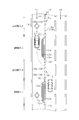
- the figure which expands and shows the entrance / exit vicinity of a car pool lane.
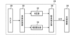
- the block diagram which shows the control structure of the road surface information acquisition apparatus of embodiment.
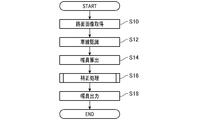
- the flowchart which shows the control flow until the road surface information acquisition apparatus of embodiment outputs the width
- the flowchart which shows a correction process.
- Explanatory drawing which shows the starting point template of the example of a change.
- Explanatory drawing which shows the end point template of the example of a change.
- FIG. 1 is an explanatory diagram showing the highway provided with the car pool lane CL as viewed from above.
- the car pool lane CL is provided in parallel with a normal traveling lane (hereinafter referred to as a normal lane 10).
- the car pool lane CL is provided on one of the left and right end portions of the highway (left end side in FIG. 1).
- the car pool lane CL is a lane (hereinafter, referred to as a lane line 12) that divides from the normal lane 10 and a lane (hereinafter, referred to as a side line 14) provided on the side opposite to the lane line 12 (left side in FIG. 1). ).
- the partition line 12 is mainly composed of a plurality of (four in the embodiment) sub-lines 12a to 12d.
- the four sublines 12a to 12d may be referred to as first to fourth sublines 12a to 12d in order from the inside to the outside of the car pool lane CL.
- These first to fourth sub-lines 12a to 12d are constituted by solid lanes.
- the first sub-line 12a and the fourth sub-line 12d are displayed in white (white line), and the second sub-line 12b and the third sub-line 12c are displayed in yellow or orange.
- the lane line 12 is provided with an entrance 16 to the normal lane 10 every predetermined distance (for example, 3 km).
- the doorway 16 is configured by a broken-line lane (hereinafter referred to as a broken-line lane 18) provided on the extended line of the fourth sub-line 12d.
- the broken line lane 18 includes a plurality of rectangular unit lines 18a arranged in the traveling direction of the vehicle A with a certain interval.
- the broken lane 18 is displayed in white. In FIG. 1, the interval between the entrances 16 is set to be shorter than the actual car pool lane CL.
- the second sub-line 12b and the third sub-line 12c are temporarily interrupted.
- the first sub-line 12a is curved toward the fourth sub-line 12d (normal lane 10 side) so as to surround the terminal ends of the second sub-line 12b and the third sub-line 12c, and is connected to the fourth sub-line 12d. is doing.
- the first sub-line 12a and the fourth sub-line 12d are interrupted when they are connected.
- the position where the broken line lane 18 starts after the first sub-line 12a and the fourth sub-line 12d are disconnected in front of the traveling direction of the vehicle A indicates the start point 20 (start position) of the doorway 16. Yes. Moreover, the location where the broken line lane 18 ends and the connecting portion of the first sub-line 12a and the fourth sub-line 12d continues indicates the end point 22 (end position) of the entrance 16.
- the side line 14 is represented by a single solid line and is provided along the extending direction of the highway.
- the side line 14 is displayed in yellow or orange.
- a traveling path excluding the entrance 16 is referred to as a normal path CL1
- a traveling path corresponding to the entrance 16 is referred to as an entrance path CL2.
- variety of the normal path CL1 of the car pool lane CL is prescribed
- the width of the entrance / exit path CL2 of the car pool lane CL is defined by the distance between the broken line lane 18 and the side line 14 (see L2 in FIG. 2). Since the dashed lane 18 is farther from the side line 14 than the first sub-line 12a, the width of the entrance / exit path CL2 of the car pool lane CL is larger than the width of the normal path CL1.
- FIG. 3 is a block diagram showing a system configuration of the road surface information acquisition device 24.
- the road surface information acquisition device 24 of this embodiment includes a camera 28 (image acquisition device), a lane recognition device 30 (lane recognition device), a determination device 32 (determination device), and a width calculator 34 (width). It is basically composed of a calculator) and a width corrector 36 (corrector).
- the road surface information acquisition device 24 is electrically connected to a support device 26 that performs lane keeping control. Then, the road surface information acquisition device 24 acquires the road surface information of the car pool lane CL (the width of the car pool lane CL), and outputs the road surface information to the support device 26.
- the camera 28 employs, for example, a CCD camera or a CMOS camera, and captures a landscape including a road surface ahead of the traveling direction of the vehicle A as a color image of three primary colors.
- the camera 28 is attached to a room mirror (not shown) of the vehicle A, for example.
- the camera 28 sequentially captures the front in the traveling direction (for example, captures every 1/24 second (one frame)), and generates image data of the captured road surface (hereinafter referred to as a road surface image).
- the shooting range of the camera 28 includes at least the entire width direction (left-right direction) of the car pool lane CL while the vehicle A is traveling on the car pool lane CL. That is, while the vehicle A travels in the car pool lane CL, the lane marking 12 and the side line 14 of the car pool lane CL are always photographed by the camera 28.
- the lane recognizer 30 recognizes the lane (division line 12 and side line 14) of the car pool lane CL based on the road surface image taken by the camera 28.
- the lane recognizer 30 extracts a lane from the photographed road surface image by known image processing, and specifies the position and type of the lane. For example, the lane recognizer 30 performs edge detection processing on the road surface image and extracts edge points.
- the lane recognizer 30 extracts edge points using a general high-pass filter.
- the point where the R (red) and G (green) signal components exceed a predetermined threshold and the B (blue) signal component falls below a predetermined threshold is yellow (or Orange) edge point.
- the edge point of the lane displayed in yellow that is, the side line 14, the first sub line 12a, and the fourth sub line 12d
- the edge point of the lane displayed in yellow that is, the side line 14, the first sub line 12a, and the fourth sub line 12d
- the lane recognizer 30 sets a white edge point at a point where all the signal components of R, G, and B exceed the threshold in the output of the high-pass filter. Thereby, the edge point of the lane displayed in white (namely, the 2nd subline 12b, the 3rd subline 12c, and the broken line lane 18) can be extracted.
- the lane recognizer 30 performs a known Hough transform process on the extracted edge points to recognize the position and type of the lane. That is, the lane recognizer 30 recognizes the side lines 14 and the lane markings 12 constituting the lanes of the car pool lane CL, and specifies the positions of these lanes. Further, the lane recognizer 30 recognizes the first to fourth sub-lines 12a to 12d and the broken lane 18 constituting the lane marking 12, respectively, and specifies their positions.
- the determiner 32 determines (recognizes) the start point 20 and the end point 22 of the entrance / exit 16 of the car pool lane CL based on the lane marking 12 recognized by the lane recognizer 30. That is, the determiner 32 determines the start point 20 of the entrance 16 from the lane marking 12 recognized by the lane recognizer 30 when the vehicle A passes the start point 20 of the entrance 16. The determination unit 32 determines the end point 22 of the entrance / exit 16 from the lane marking 12 recognized by the lane recognizer 30 when the vehicle A passes the end point 22 of the entrance / exit 16.
- the determiner 32 determines that the vehicle A is passing through the doorway 16 based on the lane line 12 recognized by the lane recognizer 30 while the vehicle A is traveling on the entrance / exit path CL2 of the car pool lane CL. .
- the determiner 32 determines the start point 20 and the end point 22 of the entrance 16 based on the broken line lane 18 of the lane marking 12.
- the lane marking 12 changes from the first to fourth sublines 12a to 12d, which are four solid lines, to the broken lane 18 that is one broken line. To do. Therefore, the determiner 32 determines that the starting point 20 of the entrance 16 is reached when the lane of the car pool lane CL recognized by the lane recognizer 30 changes from a solid line to a broken line. When the determiner 32 determines the start point 20 of the entrance / exit 16, the entrance / exit flag indicating that the vehicle A is traveling on the entrance / exit path CL2 is turned ON.
- the determiner 32 determines that the vehicle A is passing through the doorway 16 while the lane recognizer 30 recognizes the broken line lane 18 (broken line 12).
- the determiner 32 determines that the end point 22 of the entrance 16 is reached when the lane of the car pool lane CL recognized by the lane recognizer 30 changes from a broken line to a solid line.
- the determiner 32 turns off the entrance / exit flag.
- the width calculator 34 calculates the width of the car pool lane CL based on the lane recognized by the lane recognizer 30. Specifically, the width calculator 34 calculates the width of the car pool lane CL by obtaining the distance between the side line 14 recognized by the lane recognizer 30 and the lane marking 12.
- the width calculator 34 uses the distance between the lane closest to the vehicle A (that is, the first auxiliary line 12a) and the side line 14 in the normal road CL1 of the car pool lane CL as the width. The calculation is set (see L1 and L3 in FIG. 2). On the other hand, in the entrance / exit path CL2 of the car pool lane CL, the width calculator 34 is set to calculate the distance between the broken line lane 18 and the side line 14 as the width (see L2 in FIG. 2). That is, the width value calculated by the width calculator 34 is larger in the entrance / exit path CL2 than in the normal path CL1.
- the width calculator 34 includes a storage unit (not shown) such as a RAM that can rewrite data, and stores and updates the calculated widths for the past several frames (several seconds) in the storage unit.
- a storage unit such as a RAM that can rewrite data, and stores and updates the calculated widths for the past several frames (several seconds) in the storage unit.
- the width corrector 36 corrects the width value calculated by the width calculator 34 based on the determination result of the determiner 32. Specifically, when the determiner 32 has not determined the starting point 20 (entrance / exit 16) of the entrance / exit 16, the width corrector 36 uses the width value calculated by the width calculator 34 as it is in the current car pool lane CL. Decide as width. That is, the width corrector 36 adopts the width value calculated by the width calculator 34 without being corrected on the normal road CL1.
- the determiner 32 determines the starting point 20 of the entrance / exit 16 (that is, when the vehicle A reaches the entrance / exit 16)
- the vehicle A passes through the entrance / exit 16 (runs on the entrance / exit path CL2).
- the width of the entrance 16 calculated by the width calculator 34 is larger than the width calculated while traveling on the normal road CL1. If the calculated value is adopted as the width of the car pool lane CL and output to the support device 26 as it is, the support device 26 determines that the width of the car pool lane CL has increased.
- the support device 26 sets the target travel line X at a position shifted to the entrance 16 side (normal lane 10 side) (see the two-dot chain line in FIG. 2).
- the width corrector 36 cancels the width calculated by the width calculator 34 thereafter.
- the width corrector 36 determines the width value calculated by the width calculator 34 (that is, the width value of the normal road CL1) as the current width before the determiner 32 determines the starting point 20 of the entrance 16. .
- the width corrector 36 is the width value stored before the determination unit 32 determines the starting point 20 of the entrance 16 among the width values stored in the storage unit of the width calculator 34 (FIG. 2). Read from L1). Then, the read value is determined as the width of the current car pool lane CL. At this time, the width corrector 36 reads the width value of the portion of the normal path CL1 where the first sub-line 12a is parallel to the side line 14 from the storage unit.
- the width corrector 36 is calculated by the width calculator 34 while the vehicle A passes through the doorway 16 (while the vehicle A travels on the doorway CL2) and before the determiner 32 determines the starting point 20 of the doorway 16. Maintain the width value as a width. That is, while the determiner 32 continues to determine that the vehicle is passing through the doorway 16 (while the lane recognizer 30 recognizes the broken line lane 18), the width corrector 36 determines the value of the width on the normal road CL1 (FIG. 2). (See L1)) as the current width.
- the width corrector 36 determines the width value calculated by the width calculator 34 (see L 3 in FIG. 2) as the width of the car pool lane CL.
- the width corrector 36 adopts the width value calculated by the width calculator 34 during traveling on the normal road CL1 while the vehicle A travels on the entrance / exit path CL2 of the car pool lane CL. Further, when the vehicle A travels on the normal road CL1 of the car pool lane CL, the width value calculated by the width calculator 34 is adopted as it is.
- the width corrector 36 outputs the determined width of the car pool lane CL to the support device 26.
- the support device 26 sets the target travel line X based on the input width of the car pool lane CL. That is, the target travel line X is set so as to pass through the middle of the width input from the width corrector 36.
- the assisting device 26 assists the driver in driving the vehicle A so as to travel along the target travel line X.
- FIG. 4 is a flowchart showing a control flow until the road surface information acquisition device 24 determines the width of the car pool lane CL.
- step S10 while the vehicle A is traveling on the car pool lane CL, the camera 28 captures a road surface ahead in the traveling direction of the car pool lane CL, and acquires a road surface image. The road surface image acquired by the camera 28 is sent to the lane recognizer 30.
- step S12 the lane recognizer 30 recognizes each lane of the car pool lane CL from the road surface image. That is, the lane recognizer 30 recognizes the side line 14 and the lane marking 12 (the first to fourth sub-lines 12a to 12d or the broken lane 18) of the car pool lane CL, and grasps the position of each lane.
- the width calculator 34 calculates the width of the car pool lane CL based on the lane recognized by the lane recognizer 30.
- the width calculator 34 calculates the distance between the side line 14 recognized by the lane recognizer 30 and the first sub line 12a as the width.
- the width calculator 34 calculates the distance between the side line 14 recognized by the lane recognizer 30 and the broken line lane 18 as the width.
- the width calculator 34 stores the calculated width in the storage unit as needed.
- step S16 a correction process for correcting the calculated value is executed. This correction process will be described later.
- step S18 when the current width of the car pool lane CL is determined in the correction process, the determined width is output to the support device 26, and the flow is completed.
- step S20 (When the vehicle is traveling on a normal road) First, the case where the vehicle A is traveling on the normal road CL1 of the car pool lane CL in step S20 will be described. It is assumed that the entrance / exit flag of the determiner 32 is set to OFF. When the correction process is started, it is determined whether or not the entrance / exit flag of the determiner 32 is ON. If it is determined in step S20 that the entrance / exit flag is OFF, the process proceeds to step S22.
- step S22 it is determined whether or not the determiner 32 has determined the starting point 20 of the entrance 16.
- the determiner 32 determines whether or not the start point 20 of the entrance 16 is based on the lane marking 12 recognized by the lane recognizer 30 in step S12.
- the lane recognizer 30 recognizes the first to fourth sublines 12a to 12d as the lane marking 12. For this reason, the determination unit 32 does not determine the start point 20 of the entrance / exit 16 in step S22, and the process proceeds to step S24.
- step S24 the width corrector 36 determines the value calculated by the width calculator 34 in step S14 as the width of the car pool lane CL. That is, while the vehicle A is traveling on the normal road CL1, the distance between the side line 14 and the first sub line 12a is determined as the width of the car pool lane CL (see L1 and L3 in FIG. 2). When the width of the car pool lane CL is determined, the correction process is completed.
- step S20 the entrance / exit flag is OFF, and in step S22, it is determined whether or not the determiner 32 determines the starting point 20 of the entrance / exit 16.
- the lane marking 12 changes from a solid fourth sub-line 12d (first sub-line 12a) to a broken-line broken lane 18. That is, since the lane recognized by the lane recognizer 30 changes from a solid line to a broken line, the determination unit 32 determines the starting point 20 of the entrance / exit 16 in step S22. When the determiner 32 determines the starting point 20 of the entrance / exit 16, the entrance / exit flag is turned ON in step S26.
- the width of the car pool lane CL calculated by the width calculator 34 in step S14 is the distance from the side line 14 to the first sub line 12a (FIG. 2). From the side line 14 to the broken line lane 18 (see L2 in FIG. 2). Therefore, if the width of the entrance / exit path CL2 calculated by the width calculator 34 is adopted as it is, the target travel line X set by the support device 26 is curved toward the entrance / exit 16 (see the two-dot chain line in FIG. 2).
- the width corrector 36 cancels the width value calculated by the width calculator 34 in step S14 in step S28.
- the width corrector 36 determines the width value calculated by the width calculator 34 before the determiner 32 determines the starting point 20 of the entrance 16 as the current width. That is, the width corrector 36 determines, as the current width, the width value stored before the determination unit 32 determines the starting point 20 of the entrance 16 in the width stored in the storage unit of the width calculator 34.
- the width of the car pool lane CL when the vehicle A reaches the doorway 16 is the width value of the previous car pool lane CL (that is, the normal road CL1) (see L1 in FIG. 2). . Therefore, the target travel line X set by the support device 26 using this width is positioned on the extension line of the target travel line X set when traveling on the normal road CL1 (see the one-dot chain line in FIG. 2). Accordingly, it is possible to prevent the target travel line X from being curved and set to the entrance / exit 16 side due to the actual width of the entrance / exit path CL2.
- step S20 is affirmed and the process proceeds to step S32.
- the lane recognizer 30 continues to recognize the broken line lane 18 while the vehicle A travels on the entrance / exit road CL2.
- the determiner 32 determines that the vehicle A is passing through the doorway 16.
- the width calculated by the width calculator 34 in step S14 is the distance from the side line 14 to the broken line lane 18 (see L2 in FIG. 2).
- step S32 the width corrector 36 cancels the width calculated by the width calculator 34 in step S34.
- step S36 the width corrector 36 maintains the width value calculated by the width calculator 34 before the determiner 32 determines the starting point 20 of the entrance 16 as the current width. That is, the width corrector 36 maintains the value determined in step S30 as the width of the current car pool lane CL while determining that the determiner 32 is passing through the entrance 16.
- the width of the car pool lane CL is maintained at the value of the width of the normal road CL1 (L1 in FIG. 2) while the vehicle A is traveling on the entrance / exit road CL2. Therefore, the target travel line X set by the support device 26 while passing through the entrance / exit path CL2 is provided on an extension line of the target travel line X set on the normal path CL1. Thereby, it is possible to avoid setting the target travel line X so as to bend toward the entrance / exit 16 along the actual width of the entrance / exit path CL2.
- the width corrector 36 determines whether the determiner 32 has determined the entrance / exit 16 in step S32.
- step S40 the lane recognized by the lane recognizer 30 changes from the broken lane 18 to the solid fourth sub-line 12d (first sub-line 12a). For this reason, the lane recognizing device 30 does not recognize the broken line lane 18, and the determining device 32 does not determine that the vehicle is passing the entrance / exit 16 in step S ⁇ b> 32.
- step S38 the lane recognized by the lane recognizer 30 changes from a broken line to a solid line, whereby the determiner 32 determines the end point 22 of the entrance / exit 16.
- the determiner 32 turns off the entrance / exit flag in step S40.
- the width corrector 36 determines the value calculated by the width calculator 34 in step S14 as the current width in step S24.
- the width of the normal road CL1 (see L3 in FIG. 2) calculated by the width calculator 34 in real time is output to the support device 26. Therefore, the target travel line X set by the support device 26 appropriately reflects the width of the normal road CL1.
- the road surface information acquisition device has the following effects.
- the width corrector 36 corrects the width calculated by the width calculator 34 based on the determination result of the determiner 32. Accordingly, by correcting the value calculated by the width calculator 34 when passing through the entrance / exit 16 of the car pool lane CL, the width of the car pool lane CL contributing to stable traveling of the vehicle A can be obtained.
- the determiner 32 determines the start point 20 and the end point 22 of the entrance / exit 16 of the car pool lane CL based on the broken line lane 18 recognized by the lane recognizer 30. That is, since the determination device 32 determines the start point 20 and the end point 22 of the entrance / exit 16 based on the characteristic display mode of the lane indicating the entrance / exit 16 of the car pool lane CL, the start point 20 and the end point 22 are accurately recognized. be able to.
- the width corrector 36 cancels the width calculated by the width calculator 34. Then, the width corrector 36 determines the width value calculated by the width calculator 34 before the determiner 32 determines the starting point 20 of the entrance 16 as the current width. That is, when the starting point 20 of the entrance / exit 16 is determined, the width corrector 36 adopts the value of the width of the car pool lane CL before reaching the entrance / exit 16 instead of the actual width of the car pool lane CL at the entrance / exit 16. To do. Therefore, even when the vehicle A reaches the entrance / exit path CL2, the value of the width of the car pool lane CL that contributes to the stable traveling of the vehicle A can be obtained.
- the determiner 32 determines that the vehicle A is passing through the doorway 16 while the lane recognizer 30 recognizes the broken line lane 18.
- the width corrector 36 cancels the width calculated by the width calculator 34 and maintains the value of the width before reaching the entrance 16 at the current width. That is, while the vehicle A passes through the entrance / exit 16, the value of the width before the arrival at the entrance / exit 16 is continuously adopted instead of the actual width at the entrance / exit 16. Therefore, the width of the car pool lane CL that contributes to stable traveling of the vehicle A can be obtained even while passing through the doorway 16.
- the width corrector 36 directly adopts the width calculated by the width calculator 34 as the current width. That is, since the width corrector 36 uses the actual width of the car pool lane CL after passing through the doorway 16, the width of the car pool lane CL can be accurately grasped. Therefore, the width of the car pool lane CL that contributes to stable traveling of the vehicle A can be obtained even after returning to the normal road CL1.
- the determiner 32 determines the starting point 20 of the entrance 16 when the lane marking 12 recognized by the lane recognizer 30 changes from a solid line to a broken line. That is, since the determiner 32 determines the start point 20 of the entrance / exit 16 based on the characteristic display mode of the lane marking 12 indicating the start point 20 of the entrance / exit 16, the start point 20 of the entrance / exit 16 can be reliably determined.
- the determiner 32 determines the end point 22 of the entrance / exit 16 when the lane marking 12 recognized by the lane recognizer 30 changes from a broken line to a solid line. That is, since the determiner 32 determines the end point 22 of the entrance / exit 16 based on the characteristic display mode of the lane marking 12 indicating the end point 22 of the entrance / exit 16, the end point 22 of the entrance / exit 16 can be reliably determined.
- the determiner 32 when the lane marking 12 recognized by the lane recognizer 30 changes from a solid line (first to fourth sub-lines 12a to 12d) to a broken line (dashed lane 18), the determiner 32 starts the starting point 20 of the entrance / exit 16. Was judged. Further, when the lane marking 12 recognized by the lane recognizer 30 changes from a broken line (dashed lane 18) to a solid line (first to fourth sublines 12a to 12d), the determiner 32 determines the end point 22 of the entrance / exit 16 did. That is, in the embodiment, the start point 20 and the end point 22 of the entrance / exit 16 are determined from the change in the type of lane that occurs at the start point 20 and the end point 22 of the entrance / exit 16.
- the determiner 32 determines the start point 20 and the end point 22 of the entrance 16. It comes to judge. That is, in the modified example, the start point 20 and the end point 22 of the entrance / exit 16 are determined from the shape of the lane marking 12 indicating the start point 20 and the end point 22 of the entrance / exit 16.
- the lane recognizer 30 recognizes the form indicating the start point 20 and the end point 22 of the entrance 16 by pattern matching the form of the lane indicating the start point 20 and the end point 22 of the entrance 16. Yes.
- a template as shown in FIGS. 6 and 7 is stored in the lane recognizer 30 in advance. 6 is a template used when searching the start point 20 of the entrance 16 (hereinafter referred to as a start point template 40), and FIG. 7 is a template used when searching the end point 22 of the entrance 16 (referred to as an end point template 42). ).
- the starting point 20 of the entrance / exit 16 is connected in close proximity as the first auxiliary line 12a and the fourth auxiliary line 12d move forward in the traveling direction of the vehicle A, as shown in FIG. And after the 1st subline 12a and the 4th subline 12d connect, the unit line 18a of the broken line lane 18 appears ahead of the advancing direction of the vehicle A.
- FIG. That is, the starting point 20 of the entrance / exit 16 is such that the lane marking 12 having a shape in which two lanes are adjacently connected to the front in the traveling direction of the vehicle A and the rectangular lane marking 12 are in front of the traveling direction of the vehicle A. They are located side by side.
- the starting point template 40 has a figure imitating the form of the partition line 12 indicating the starting point 20 of the entrance 16 as shown in FIG. That is, a figure in which a form 41 in which two lines are closely connected upward in FIG. 6 and a rectangular form 44 are arranged in the upper direction in FIG. 6 is adopted as the starting point 20 plate.
- the end point 22 of the entrance / exit 16 is separated from the unit line 18a of the broken lane 18 by the first sub-line 12a and the fourth sub-line 12d moving forward in the traveling direction of the vehicle A.
- a shape that spreads out appears. That is, the end point 22 of the entrance / exit 16 has a rectangular lane line 12 and a lane line 12 having a shape in which two lanes are separated and spread forward in the traveling direction of the vehicle A and are aligned in front of the traveling direction of the vehicle A. Is located at.
- the end point template 42 has a shape imitating the form of the partition line 12 indicating the end point 22 of the entrance 16 as shown in FIG. That is, a figure in which a rectangular form (rectangular) form 46 and a form 48 in which two lines are separated and expand toward the upper side of FIG. 7 are arranged in the upper part of FIG. 7 is adopted as the end point 22 plate.
- the lane recognizer 30 searches the road image taken by the camera 28 for a form indicating the start point 20 and the end point 22 of the entrance 16 using the start point template 40 and the end point template 42 by a known matching method.
- the determiner 32 determines the start point 20 and the end point 22 of the entrance / exit 16.
- the operation of the road surface information acquisition device 24 according to the modified example is the same as that of the embodiment except for the method of recognizing the start point 20 and the end point 22 of the entrance / exit 16 by the lane recognizer 30. Further, the control flow of the modified example is the same as the flowcharts of FIGS. 4 and 5 described in the embodiment. Therefore, the description of the operation of the road surface information acquisition device 24 according to the modified example is omitted.
- the road surface information acquisition device 24 according to the modified example described above has the following effects.
- the determiner 32 determines the start point 20 of the entrance 16. That is, since the determiner 32 recognizes the start point 20 of the entrance 16 based on a form specific to the start point 20 of the entrance 16, the start point 20 of the entrance 16 can be reliably determined.
- the determiner 32 determines the end point 22 of the entrance 16. That is, since the determiner 32 recognizes the end point 22 of the entrance / exit 16 based on the form specific to the end point 22 of the entrance / exit 16, the end point 22 of the entrance / exit 16 can be reliably determined.
- the lane recognizer recognizes each lane by detecting the edge of the road surface image.
- various lane templates that is, side lines and lane markings
- the lanes may be recognized by matching using the templates.
- a camera that acquires a color image is used as the image acquisition device, but it is not always necessary to acquire a road surface image as a color image.
- An image acquisition device that acquires a road surface image as a monochrome image may be employed as long as the type and position of the lanes that make up the car pool lane can be properly recognized.
- the support device performs lane keeping control using the width of the car pool lane acquired by the road surface information acquisition device.
- the width acquired by the road surface information acquisition device may be used for purposes other than lane keeping control.
- the target travel line may be set based on the width of the car pool lane acquired by the road surface information acquisition device, and the support device may warn the driver when the vehicle greatly deviates from the target travel line.
Landscapes
- Engineering & Computer Science (AREA)
- Physics & Mathematics (AREA)
- General Physics & Mathematics (AREA)
- Theoretical Computer Science (AREA)
- Multimedia (AREA)
- Mechanical Engineering (AREA)
- Geometry (AREA)
- Computer Vision & Pattern Recognition (AREA)
- Automation & Control Theory (AREA)
- Transportation (AREA)
- Traffic Control Systems (AREA)
Abstract
カープールレーンの出入口を適確に把握して、カープールレーンの適切な幅員を取得し得る路面情報取得装置(24)を提供する。路面情報取得装置(24)は、カープールレーンの車両前方の路面を撮影して路面画像を取得するカメラ(28)と、カメラ(28)が取得した路面画像に基づいて、カープールレーンの路面に表示された車線を認識する車線認識器(30)とを備える。また、路面情報取得装置(24)は、車線認識器(30)が認識した区画線に基づいて、出入口の始点および終点を判定する判定器(32)と、車線認識器(30)が認識した車線に基づいて、カープールレーンの幅員を算出する幅員算出器(34)とを備える。路面情報取得装置(24)は更に、判定器(32)の判定結果に基づいて、幅員算出器(34)が算出した幅員を補正する幅員補正器(36)を備える。判定器(32)は、車線認識器(30)が認識した破線状の破線車線に基づいて、出入口の始点および終点を判定する。
Description
本発明は、撮影された車両前方の路面画像に基づいて、カープールレーンの路面情報を取得する路面情報取得装置に関するものである。
車両が走行する道路の路面情報を取得して、ドライバーの運転をアシストする各種の支援装置が提案されている。例えばレーンキーピング制御を行う支援装置では、車両が走行している道路の撮影画像から道路の幅員を認識し、当該幅員の略中央に設定した目標走行線上を車両が走行するようにドライバーの運転をアシストする。
ところで、特に米国の大都市の高速道路には、カープールレーンと呼ばれる走行レーンが採用されている。このカープールレーンは、車両の走行台数の減少や電気自動車等の環境性能に優れた車両(いわゆるエコカー)の普及促進を図るために導入されている。
具体的には、相乗りの車両やエコカーのみがカープールレーンの走行を許され、ドライバーのみが乗車した車両や所定の環境基準を満たしていない車両は、カープールレーンの走行が規制される。そのため、カープールレーンは、通常レーンに比べて走行車両が少なく空いているため、カープールレーンを利用することで走行時間の大幅な短縮を図ることができる。
例えば特許文献1には、このようなカープールレーンにおいても、ドライバーの運転をアシストする支援装置が提案されている。
ところで、カープールレーンは、通常レーンと平行して設けられる場合が多く、カープールレーンと通常レーンとの間は車線(区画線)により区画されている。この区画線は、基本的に複数(例えば4本)の実線からなる部分で構成されている。また、区画線には、所定の距離毎にカープールレーンの出入口が設けられている。この出入口は、1本の破線によって表されており、車両は、出入口を介してカープールレーンから通常レーンへ出入りすることができる。
一般的なカープールレーンでは、出入口の幅員が当該出入口側(通常レーン側)へ拡がっており、出入口以外の部分に比べて幅員が大きくなっている。このため、車両がカープールレーンの出入口を通過する際、支援装置がカープールレーンの幅員が広くなったと判断して、目標走行線を出入口側(通常レーン側)に寄った位置に設定してしまう。そして、車両がカープールレーンの出入口を通過すると、今度は、支援装置がカープールレーンの幅員が狭くなったと判断して、目標走行線をもとの位置に設定し直すことになる。従って、出入口を通過する度に目標走行線が湾曲(蛇行)するように設定されてしまい、車両の走行が不安定となる虞がある。
上記点に鑑み、カープールレーンの出入口を適確に把握して、カープールレーンの適切な幅員を取得し得る路面情報取得装置を提供することが望ましいであろう。
本発明の例示的な実施形態による装置は、通常レーンとの出入口が所要の間隔を置いて設けられ、前記出入口での幅員が当該出入口以外での幅員よりも大きく設定されたカープールレーンの路面情報取得装置であって、前記カープールレーンの車両前方の路面を撮影して路面画像を取得する画像取得器と、前記画像取得器が取得した前記路面画像に基づいて、前記カープールレーンの路面に表示された車線を認識する車線認識器と、前記車線認識器が認識した前記車線であって、前記カープールレーンと通常レーンとを区画する区画線に基づいて、前記出入口の始点を判定する判定器と、前記車線認識器が認識した前記車線に基づいて、カープールレーンの幅員を算出する幅員算出器と、前記判定器の判定結果に基づいて、前記幅員算出器が算出した前記幅員を補正する補正器と、を備え、前記判定器は、前記車線認識器が認識した破線状の前記区画線に基づいて、前記出入口の始点を判定する。
上記の構成によれば、補正器は、判定器の判定結果に基づいて、幅員算出器が算出した幅員を補正する。従って、カープールレーンの出入口を通過する際に、幅員算出器が算出した値を適切に補正することで、車両の安定的な走行に資するカープールレーンの幅員を得ることができる。
ここで、一般的に、カープールレーンの出入口では、カープールレーンと通常レーンとを区画する区画線が破線状に表される場合が多い。そこで、判定器は、車線認識器が認識した破線状の区画線に基づいて、カープールレーンの出入口の始点および終点を判定するようになっている。すなわち、判定器は、出入口を示す車線の特有な態様に基づいて出入口の始点および終点を判定するから、当該始点および終点を適確に認識することができる。
次に、本発明の実施形態に係る路面情報取得装置について、添付図面を参照しながら、以下説明する。
(カープールレーンについて)
先ず始めに、路面情報取得装置24が路面情報を取得する対象であるカープールレーンCLについて説明を行う。
先ず始めに、路面情報取得装置24が路面情報を取得する対象であるカープールレーンCLについて説明を行う。
図1は、カープールレーンCLが設けられたハイウェイを上方から見た状態で示す説明図である。カープールレーンCLは、通常の走行レーン(以下、通常レーン10と称する)と平行に設けられている。カープールレーンCLは、ハイウェイの左右一方の端部側(図1では、左端側)に設けられている。カープールレーンCLは、通常レーン10と区画する車線(以下、区画線12と称する)と、当該区画線12とは反対側(図1では、左側)に設けた車線(以下、側線14と称する)とによって規定されている。
図1,図2に示すように、区画線12は、主として複数(実施形態では4つ)の副線12a~12dで構成されている。なお、4つの副線12a~12dをカープールレーンCLの内側から外側の順に第1~第4副線12a~12dと称する場合がある。これら第1~第4副線12a~12dは、実線の車線で構成されている。このうち第1副線12aおよび第4副線12dは、白色(白線)で表示され、第2副線12bおよび第3副線12cは、黄色またはオレンジ色で表示されている。
区画線12には、所定の距離(例えば3km)毎に通常レーン10への出入口16が設けられている。この出入口16は、第4副線12dの延長線上に設けた破線状の車線(以下、破線車線18と称する)で構成されている。破線車線18は、複数の矩形状の単位線18aが車両Aの進行方向に一定の間隔を空けて並んで構成されている。この破線車線18は、白色で表示されている。なお、図1では、出入口16の間隔を現実のカープールレーンCLよりも短く設定してある。
ここで、図2に示すように、区画線12の出入口16の近傍では、第2副線12bおよび第3副線12cが一旦途切れている。また、第1副線12aは、第2副線12bおよび第3副線12cの終端を囲うように第4副線12d側(通常レーン10側)に湾曲し、当該第4副線12dと連結している。そして、第1副線12aおよび第4副線12dは、両者が連結したところで途切れている。
すなわち、車両Aの進行方向の前方において、第1副線12aおよび第4副線12dが連結して途切れた後、破線車線18が開始する箇所が出入口16の始点20(開始位置)を示している。また、破線車線18が終了して第1副線12aおよび第4副線12dの連結部分が続く箇所が出入口16の終点22(終了位置)を示している。
側線14は、1本の実線で表されており、ハイウェイの延在方向に沿って設けられている。側線14は、黄色またはオレンジ色で表示されている。
ここで、カープールレーンCLにおいて、出入口16を除いた走行路を通常路CL1と称し、出入口16に対応する走行路を出入口路CL2と称する。そして、カープールレーンCLの通常路CL1の幅員は、第1副線12aと側線14との間の距離で規定される(図2のL1,L3参照)。但し、通常路CL1の幅員として、第1副線12aが第4副線12dに向けて湾曲する部分は除かれる。一方、カープールレーンCLの出入口路CL2の幅員は、破線車線18と側線14との間の距離で規定される(図2のL2参照)。破線車線18は、第1副線12aよりも側線14から離間しているため、カープールレーンCLの出入口路CL2の幅員は、通常路CL1の幅員よりも大きくなる。
次に、本実施形態の路面情報取得装置24について説明する。図3は、路面情報取得装置24のシステム構成を示すブロック図である。
(路面情報取得装置について)
図3に示すように、本実施形態の路面情報取得装置24は、カメラ28(画像取得器)、車線認識器30(車線認識器)、判定器32(判定器)、幅員算出器34(幅員算出器)および幅員補正器36(補正器)から基本的に構成される。路面情報取得装置24は、レーンキーピング制御を実施する支援装置26に電気的に接続されている。そして、路面情報取得装置24は、カープールレーンCLの路面情報(カープールレーンCLの幅員)を取得して、当該路面情報を支援装置26に出力する。
図3に示すように、本実施形態の路面情報取得装置24は、カメラ28(画像取得器)、車線認識器30(車線認識器)、判定器32(判定器)、幅員算出器34(幅員算出器)および幅員補正器36(補正器)から基本的に構成される。路面情報取得装置24は、レーンキーピング制御を実施する支援装置26に電気的に接続されている。そして、路面情報取得装置24は、カープールレーンCLの路面情報(カープールレーンCLの幅員)を取得して、当該路面情報を支援装置26に出力する。
カメラ28は、例えばCCDカメラやCMOSカメラが採用され、車両Aの走行方向前方の路面を含む風景を三原色のカラー画像として撮影する。カメラ28は、車両Aの例えばルームミラー(図示せず)に取り付けられる。カメラ28は、走行方向の前方を逐次撮影(例えば24分の1秒(1フレーム)毎に撮影)し、撮影した路面の画像データ(以下、路面画像と称する)を生成する。カメラ28の撮影範囲は、車両AがカープールレーンCLを走行中、少なくともカープールレーンCLの幅方向(左右方向)の全体が含まれる。すなわち、車両AがカープールレーンCLを走行する間、カープールレーンCLの区画線12および側線14は、カメラ28で常に撮影されるようになっている。
車線認識器30は、カメラ28が撮影した路面画像に基づいてカープールレーンCLの車線(区画線12および側線14)を認識する。車線認識器30は、撮影された路面画像に対し、公知の画像処理によって車線を抽出し、車線の位置および種類を特定する。例えば、車線認識器30は、路面画像に対しエッジ検出処理を行ってエッジ点を抽出する。
ここで、車線認識器30は、一般的なハイパスフィルタを用いてエッジ点を抽出する。そして、ハイパスフィルタの出力のうち、R(赤)およびG(緑)の信号成分が所定の閾値を超え、かつ、B(青)の信号成分が所定の閾値を下回る点については、黄色(またはオレンジ)のエッジ点とする。これにより、黄色表示された車線(すなわち、側線14、第1副線12aおよび第4副線12d)のエッジ点を抽出することができる。
一方、車線認識器30は、ハイパスフィルタの出力のうち、R、G、Bの全ての信号成分が閾値を超える点について、白色のエッジ点とする。これにより、白色表示された車線(すなわち、第2副線12b、第3副線12cおよび破線車線18)のエッジ点を抽出することができる。
次に、車線認識器30は、抽出されたエッジ点に対し、公知のハフ変換処理を行って車線の位置および種類を認識する。すなわち、車線認識器30は、カープールレーンCLの車線を構成する側線14および区画線12を認識し、これらの車線の位置を特定する。更に、車線認識器30は、区画線12を構成する第1~第4副線12a~12dおよび破線車線18をそれぞれ認識し、それらの位置を特定する。
判定器32は、車線認識器30が認識した区画線12に基づいて、カープールレーンCLの出入口16の始点20および終点22を判定(認識)する。すなわち、判定器32は、車両Aが出入口16の始点20を通過する際に、車線認識器30が認識した区画線12から出入口16の始点20を判定する。また、判定器32は、車両Aが出入口16の終点22を通過する際に、車線認識器30が認識する区画線12から出入口16の終点22を判定する。
更に、判定器32は、車両AがカープールレーンCLの出入口路CL2を走行中、車線認識器30が認識する区画線12に基づいて車両Aが出入口16を通過中である旨の判定をする。
次に、判定器32の具体的な判定手法について説明する。前述のように、カープールレーンCLの出入口16は、破線車線18によって表されている。そこで、判定器32は、区画線12の破線車線18に基づいて、出入口16の始点20および終点22を判定する。
カープールレーンCLを走行する車両Aが出入口16に到達する際、区画線12は、4本の実線である第1~第4副線12a~12dから1本の破線である破線車線18に変化する。そこで、判定器32は、車線認識器30が認識したカープールレーンCLの車線が実線から破線に変化した際に、出入口16の始点20であると判定する。判定器32は、出入口16の始点20を判定すると、車両Aが出入口路CL2を走行中であることを示す出入口フラグをONにする。
また、カープールレーンCLの出入口16を車両Aが通過中である場合(出入口路CL2を車両Aが走行中の場合)、1本の破線車線18が継続することになる。そこで、判定器32は、車線認識器30が破線車線18(破線状の区画線12)を認識する間、車両Aが出入口16を通過中であると判定する。
車両Aが出入口16の終点22を通過する場合、区画線12は、1本の破線車線18から4本の第1~第4副線12a~12dに変化する。そこで、判定器32は、車線認識器30が認識したカープールレーンCLの車線が破線から実線に変化した際に、出入口16の終点22であると判定する。判定器32は、出入口16の終点22を判定すると、出入口フラグをOFFにする。
幅員算出器34は、車線認識器30が認識した車線に基づいて、カープールレーンCLの幅員を算出する。具体的には、幅員算出器34は、車線認識器30が認識した側線14および区画線12の間の距離を求めることで、カープールレーンCLの幅員を算出する。
ここで、幅員算出器34は、カープールレーンCLの通常路CL1では、区画線12のうち車両Aに最も近い車線(すなわち、第1副線12a)と側線14との間の距離を幅員として算出するよう設定されている(図2のL1,L3参照)。一方、カープールレーンCLの出入口路CL2では、幅員算出器34は、破線車線18と側線14との間の距離を幅員として算出するよう設定されている(図2のL2参照)。すなわち、幅員算出器34が算出する幅員の値は、通常路CL1よりも出入口路CL2の方が大きくなる。
幅員算出器34は、データを書き換え可能なRAM等の記憶部(図示せず)を備えており、算出した過去数フレーム分(数秒分)の幅員を記憶部に記憶および更新する。
幅員補正器36は、判定器32の判定結果に基づいて、幅員算出器34が算出した幅員の値を補正する。具体的には、判定器32が出入口16の始点20(出入口16)を判定していない場合、幅員補正器36は、幅員算出器34が算出した幅員の値をそのまま現在のカープールレーンCLの幅員として決定する。すなわち、幅員補正器36は、通常路CL1においては、幅員算出器34が算出した幅員の値を補正することなく、そのまま採用する。
一方、判定器32が出入口16の始点20を判定した場合(すなわち、車両Aが出入口16に到達した場合)、車両Aは出入口16を通過(出入口路CL2を走行)することになる。この場合、幅員算出器34が算出する出入口16の幅員は、通常路CL1を走行中に算出された幅員よりも大きくなる。そして、算出された値をカープールレーンCLの幅員として採用し、そのまま支援装置26に出力すれば、支援装置26は、カープールレーンCLの幅員が大きくなったと判断してしまう。その結果、支援装置26は、出入口16側(通常レーン10側)にズレた位置に目標走行線Xを設定してしまうことになる(図2の二点鎖線参照)。
そこで、幅員補正器36は、判定器32が出入口16の始点20を判定すると、以後に幅員算出器34が算出した幅員をキャンセルする。そして、幅員補正器36は、判定器32が出入口16の始点20を判定する前に幅員算出器34が算出した幅員の値(すなわち、通常路CL1の幅員の値)を現在の幅員として決定する。
具体的には、幅員補正器36は、幅員算出器34の記憶部に記憶された幅員の値のうち、判定器32が出入口16の始点20を判定する前に記憶した幅員の値(図2のL1参照)を記憶部から読み出す。そして、読み出した値を現在のカープールレーンCLの幅員に決定する。このとき、幅員補正器36は、通常路CL1において第1副線12aが側線14に対し平行となっている部分の幅員の値を記憶部から読み出すようになっている。
更に、幅員補正器36は、車両Aが出入口16を通過する間(車両Aが出入口路CL2を走行する間)、判定器32が出入口16の始点20を判定する前に幅員算出器34が算出した幅員の値を幅員として維持する。すなわち、判定器32が出入口16を通過中であると判定し続ける間(車線認識器30が破線車線18を認識する間)、幅員補正器36は、通常路CL1での幅員の値(図2のL1参照)を現在の幅員として維持する。
車両Aが出入口16を通過して通常路CL1に移行すると、カープールレーンCLの幅員が狭くなる。従って、出入口16を通過した後は、現在の幅員を出入口16に到達する前のカープールレーンCLの幅員に維持する必要がない。そこで、幅員補正器36は、判定器32が出入口16の終点22を判定すると、幅員算出器34が算出した幅員の値(図2のL3参照)をそのままカープールレーンCLの幅員として決定する。
すなわち、幅員補正器36は、車両AがカープールレーンCLの出入口路CL2を走行する間は、通常路CL1の走行時に幅員算出器34が算出した幅員の値を採用する。また、車両AがカープールレーンCLの通常路CL1を走行する場合は、幅員算出器34が算出する幅員の値をそのまま採用する。
幅員補正器36は、決定したカープールレーンCLの幅員を支援装置26に出力する。支援装置26は、入力されたカープールレーンCLの幅員に基づいて、目標走行線Xを設定する。すなわち、幅員補正器36から入力された幅員の中間を通るように目標走行線Xを設定する。そして、支援装置26は、車両Aが目標走行線Xに沿って走行するようドライバーの運転を支援する。
次に、実施形態に係る路面情報取得装置24の作用について説明する。なお、以下の説明では、車両AはカープールレーンCLを走行し続けるものとし、出入口16を介して通常レーン10に移ることはないものとする。
図4は、路面情報取得装置24がカープールレーンCLの幅員を決定するまでの制御フローを示すフローチャートである。ステップS10において、車両AがカープールレーンCLを走行中、カメラ28がカープールレーンCLの走行方向の前方の路面を撮影し、路面画像を取得する。カメラ28が取得した路面画像は、車線認識器30に送られる。ステップS12において、車線認識器30は、路面画像からカープールレーンCLの各車線を認識する。すなわち、車線認識器30は、カープールレーンCLの側線14および区画線12(第1~第4副線12a~12dまたは破線車線18)をそれぞれ認識し、各車線の位置を把握する。
次に、ステップS14において、車線認識器30が認識した車線に基づいて、幅員算出器34がカープールレーンCLの幅員を算出する。車両AがカープールレーンCLの通常路CL1を走行している場合、幅員算出器34は、車線認識器30が認識した側線14と第1副線12aとの間の距離を幅員として算出する。一方、車両AがカープールレーンCLの出入口路CL2を走行している場合、幅員算出器34は、車線認識器30が認識した側線14と破線車線18との間の距離を幅員として算出する。幅員算出器34は、算出した幅員を記憶部に随時記憶していく。
幅員算出器34が幅員を算出すると、次に、ステップS16において、当該算出された値を補正する補正処理が実行される。この補正処理については、後述する。そして、ステップS18において、補正処理でカープールレーンCLの現在の幅員が決定すると、決定された幅員が支援装置26に出力され、フローが完了する。
次に、補正処理について図5のフローチャートを参照して説明する。
(車両が通常路を走行している場合について)
先ず始めに、ステップS20において、車両AがカープールレーンCLの通常路CL1を走行している場合について説明する。なお、判定器32の出入口フラグはOFFに設定されているものとする。補正処理が開始されると、判定器32の出入口フラグがONである否か判定する。ステップS20において出入口フラグはOFFとなっていると判定された場合、処理はステップS22に移行する。
先ず始めに、ステップS20において、車両AがカープールレーンCLの通常路CL1を走行している場合について説明する。なお、判定器32の出入口フラグはOFFに設定されているものとする。補正処理が開始されると、判定器32の出入口フラグがONである否か判定する。ステップS20において出入口フラグはOFFとなっていると判定された場合、処理はステップS22に移行する。
ステップS22では、判定器32が出入口16の始点20を判定したか否かについて判定される。判定器32は、車線認識器30がステップS12で認識した区画線12に基づいて、出入口16の始点20であるか否かを判定する。
車両AがカープールレーンCLの通常路CL1を走行している場合、車線認識器30は区画線12として第1~第4副線12a~12dを認識している。このため、ステップS22において判定器32が出入口16の始点20を判定することなく、処理はステップS24に移行する。
ステップS24では、幅員補正器36は、ステップS14で幅員算出器34が算出した値をそのままカープールレーンCLの幅員として決定する。すなわち、車両Aが通常路CL1を走行中、側線14と第1副線12aとの間の距離がカープールレーンCLの幅員として決定される(図2のL1,L3参照)。カープールレーンCLの幅員が決定されると、補正処理が完了する。
(車両が通常路から出入口路に移行する場合について)
次に、車両Aが通常路CL1から出入口路CL2に移行する場合(始点20を通過する場合)について説明する。この場合、ステップS20の判定において、出入口フラグはOFFとなっており、ステップS22において判定器32が出入口16の始点20を判定しているか否が判定される。
次に、車両Aが通常路CL1から出入口路CL2に移行する場合(始点20を通過する場合)について説明する。この場合、ステップS20の判定において、出入口フラグはOFFとなっており、ステップS22において判定器32が出入口16の始点20を判定しているか否が判定される。
ここで、車両Aが通常路CL1から出入口路CL2に移行する際、区画線12は、実線の第4副線12d(第1副線12a)から破線の破線車線18に変化する。すなわち、車線認識器30が認識する車線が実線から破線に変化するので、ステップS22において判定器32が出入口16の始点20を判定する。判定器32は、出入口16の始点20を判定すると、ステップS26において出入口フラグをONにする。
ここで、車両Aが通常路CL1から出入口路CL2に移行する際、ステップS14で幅員算出器34が算出するカープールレーンCLの幅員は、側線14から第1副線12aまでの距離(図2のL1参照)から、側線14から破線車線18までの距離(図2のL2参照)へ大きくなる。従って、幅員算出器34が算出した出入口路CL2の幅員をそのまま採用すると、支援装置26が設定する目標走行線Xが出入口16側へ湾曲してしまう(図2の二点鎖線参照)。
そこで、幅員補正器36は、ステップS28において、ステップS14で幅員算出器34が算出した幅員の値をキャンセルする。そして、幅員補正器36は、ステップS30において、判定器32が出入口16の始点20を判定する前に幅員算出器34が算出した幅員の値を現在の幅員として決定する。すなわち、幅員補正器36は、幅員算出器34の記憶部に記憶された幅員において、判定器32が出入口16の始点20を判定する前に記憶された幅員の値を現在の幅員として決定する。
これにより、車両Aが出入口16に差し掛かった場合でのカープールレーンCLの幅員は、これまでのカープールレーンCL(すなわち、通常路CL1)の幅員の値(図2のL1参照)が用いられる。従って、この幅員を用いて支援装置26が設定する目標走行線Xは、通常路CL1の走行時に設定された目標走行線Xの延長線上に位置したものとなる(図2の一点鎖線参照)。従って、出入口路CL2の現実の幅員につられて目標走行線Xが出入口16側に湾曲して設定されるのを防止することができる。
(車両が出入口路を走行する場合について)
次に、車両Aが出入口路CL2を走行する場合について説明する。出入口路CL2を走行する場合、ステップS22において、判定器32によって出入口16の始点20が既に判定されており、出入口フラグはONとなっている(ステップS26参照)。従って、車両Aが出入口路CL2を走行する場合、ステップS20は肯定され、処理はステップS32に移行する。
次に、車両Aが出入口路CL2を走行する場合について説明する。出入口路CL2を走行する場合、ステップS22において、判定器32によって出入口16の始点20が既に判定されており、出入口フラグはONとなっている(ステップS26参照)。従って、車両Aが出入口路CL2を走行する場合、ステップS20は肯定され、処理はステップS32に移行する。
ここで、出入口路CL2の区画線12は、破線車線18で構成されているため、車両Aが出入口路CL2を走行する間、車線認識器30は破線車線18を認識し続けることになる。この結果、判定器32は、車両Aが出入口16を通過中であると判定する。また、車両Aが出入口路CL2を走行する場合、ステップS14で幅員算出器34が算出する幅員は、側線14から破線車線18までの距離である(図2のL2参照)。
そこで、幅員補正器36は、ステップS32において、判定器32が出入口16を通過中であると判定している場合、幅員補正器36は、ステップS34において、幅員算出器34が算出した幅員をキャンセルする。そして、幅員補正器36は、ステップS36において、判定器32が出入口16の始点20を判定する前に幅員算出器34が算出した幅員の値を現在の幅員として維持する。すなわち、幅員補正器36は、判定器32が出入口16を通過中であると判定する間、ステップS30で決定した値を現在のカープールレーンCLの幅員として維持する。
これにより、車両Aが出入口路CL2を走行中、カープールレーンCLの幅員は、通常路CL1の幅員(図2のL1)の値に維持される。従って、出入口路CL2を通過中に支援装置26が設定する目標走行線Xは、通常路CL1に設定された目標走行線Xの延長線上に設けられる。これにより、出入口路CL2の現実の幅員につられて、目標走行線Xが出入口16側に湾曲するように設定されるのを回避することができる。
(車両が出入口路から通常路に移行する場合について)
次に、車両Aが出入口路CL2から通常路CL1に移行する場合(終点22を通過する場合)について説明する。ステップS20の判定において出入口フラグはONとなっているから、幅員補正器36は、ステップS32において、判定器32が出入口16を判定しているか否か判定する。
次に、車両Aが出入口路CL2から通常路CL1に移行する場合(終点22を通過する場合)について説明する。ステップS20の判定において出入口フラグはONとなっているから、幅員補正器36は、ステップS32において、判定器32が出入口16を判定しているか否か判定する。
ここで、車両Aが出入口16から通常路CL1に移行する場合、車線認識器30が認識する車線は破線車線18から実線の第4副線12d(第1副線12a)に変化する。このため、車線認識器30は、破線車線18を認識しなくなり、ステップS32において判定器32は出入口16を通過中である旨の判定をしなくなる。そして、ステップS38において、車線認識器30が認識する車線が破線から実線に変化することで、判定器32は、出入口16の終点22を判定する。判定器32は、出入口16の終点22を判定すると、ステップS40において出入口フラグをOFFにする。
車両Aが通常路CL1に移行した後は、カープールレーンCLの幅員をステップS30で設定した値に維持する必要はなく、幅員算出器34が算出した幅員をそのまま採用すればよい。そこで、幅員補正器36は、判定器32が終点22を判定すると、ステップS24において、ステップS14で幅員算出器34が算出した値を現在の幅員として決定する。
これにより、車両Aが通常路CL1に移行した後は、幅員算出器34がリアルタイムで算出した通常路CL1の幅員(図2のL3参照)が支援装置26に出力される。従って、支援装置26によって設定される目標走行線Xは、通常路CL1の幅員を適正に反映したものとなる。
以上に説明した実施形態に係る路面情報取得装置によれば、以下の効果を奏する。
(1)幅員補正器36は、判定器32の判定結果に基づいて、幅員算出器34が算出した幅員を補正する。従って、カープールレーンCLの出入口16を通過する際に、幅員算出器34が算出した値を補正することで、車両Aの安定的な走行に資するカープールレーンCLの幅員を得ることができる。
判定器32は、車線認識器30が認識した破線車線18に基づいて、カープールレーンCLの出入口16の始点20および終点22を判定する。すなわち、判定器32は、カープールレーンCLの出入口16を示す車線の特徴的な表示態様に基づいて出入口16の始点20および終点22を判定するから、始点20および終点22を適確に認識することができる。
(2)判定器32が出入口16の始点20を判定した場合、幅員補正器36は、幅員算出器34が算出する幅員をキャンセルする。そして、幅員補正器36は、判定器32が出入口16の始点20を判定する前に幅員算出器34が算出した幅員の値を現在の幅員として決定する。すなわち、幅員補正器36は、出入口16の始点20が判定されると、出入口16におけるカープールレーンCLの現実の幅員ではなく、出入口16に到達する前のカープールレーンCLの幅員の値を採用する。従って、車両Aが出入口路CL2に到達した際においても、車両Aの安定した走行に資するカープールレーンCLの幅員の値を得ることができる。
(3)判定器32は、車線認識器30が破線車線18を認識する間、車両Aが出入口16を通過中であると判定する。そして、判定器32が出入口16を判定すると、幅員補正器36は、幅員算出器34が算出した幅員をキャンセルし、出入口16に到達する前の幅員の値を現在の幅員に維持する。すなわち、車両Aが出入口16を通過する間は、出入口16での現実の幅員ではなく、出入口16に到来する前の幅員の値が採用され続けることになる。従って、出入口16を通過中においても、車両Aの安定した走行に資するカープールレーンCLの幅員を得ることができる。
(4)幅員補正器36は、判定器32が出入口16の終点22を判定すると、幅員算出器34が算出する幅員を現在の幅員としてそのまま採用する。すなわち、幅員補正器36は、出入口16を通過した後は、現実のカープールレーンCLの幅員を採用するから、カープールレーンCLの幅員を正確に把握することができる。従って、通常路CL1に復帰した後も、車両Aの安定した走行に資するカープールレーンCLの幅員を得ることができる。
(5)判定器32は、車線認識器30が認識した区画線12が実線から破線に変化した際に、出入口16の始点20を判定する。すなわち、出入口16の始点20を示す区画線12の特徴的な表示態様に基づいて、判定器32が出入口16の始点20を判定するから、出入口16の始点20を確実に判定することができる。
(6)判定器32は、車線認識器30が認識した区画線12が破線から実線に変化した際に、出入口16の終点22を判定する。すなわち、出入口16の終点22を示す区画線12の特徴的な表示態様に基づいて、判定器32が出入口16の終点22を判定するから、出入口16の終点22を確実に判定することができる。
[変更例]
次に、変更例に係る路面情報取得装置24について以下説明する。なお、変更例においては、実施形態と相違する部分についてのみ説明し、実施形態と同一の部分については、同じ符号を付して説明を省略する。
次に、変更例に係る路面情報取得装置24について以下説明する。なお、変更例においては、実施形態と相違する部分についてのみ説明し、実施形態と同一の部分については、同じ符号を付して説明を省略する。
実施形態では、車線認識器30が認識する区画線12が実線(第1~第4副線12a~12d)から破線(破線車線18)に変化したときに、判定器32が出入口16の始点20を判定した。また、車線認識器30が認識する区画線12が破線(破線車線18)から実線(第1~第4副線12a~12d)に変化したときに、判定器32が出入口16の終点22を判定した。すなわち、実施形態では、出入口16の始点20および終点22において生ずる車線の種類の変化から出入口16の始点20および終点22を判定するものであった。
これに対し、変更例では、車線認識器30が出入口16の始点20および終点22を示す区画線12の特徴的な形態を認識した場合に、判定器32が出入口16の始点20および終点22を判定するようになっている。すなわち、変更例では、出入口16の始点20および終点22を示す区画線12の形状から出入口16の始点20および終点22を判定する。
具体的には、車線認識器30は、出入口16の始点20および終点22を示す車線の形態をパターンマッチングすることで、当該出入口16の始点20および終点22を示す形態を認識するようになっている。車線認識器30には、図6,図7に示すようなテンプレートが予め記憶されている。図6は、出入口16の始点20を探索する際に用いられるテンプレート(以下、始点テンプレート40と称する)、図7は、出入口16の終点22を探索する際に用いられるテンプレート(終点テンプレート42と称する)である。
ここで、出入口16の始点20は、図2に示すように、第1副線12aおよび第4副線12dが車両Aの進行方向の前方に向かうにつれて近接して連結している。そして、第1副線12aおよび第4副線12dが連結した後に、破線車線18の単位線18aが車両Aの進行方向の前方に現れる。すなわち、出入口16の始点20は、車両Aの進行方向の前方に向けて2つの車線が近接して連結する形状の区画線12と矩形状の区画線12とが車両Aの進行方向の前方に並んで位置している。
そこで、始点テンプレート40は、図6に示すように、出入口16の始点20を示す区画線12の形態を模した図形となっている。すなわち、2つの線が図6の上方に向けて近接して連結する形態41と矩形(長方形)の形態44とが図6の上方に向けて並んだ図形が始点20プレートとして採用されている。
一方、出入口16の終点22は、図2に示すように、破線車線18の単位線18aの後に、車両Aの進行方向の前方に向けて第1副線12aおよび第4副線12dが離間して拡がる形状が現れる。すなわち、出入口16の終点22は、矩形状の区画線12と車両Aの進行方向の前方に向けて2つの車線が離間して拡がる形状の区画線12とが車両Aの進行方向の前方に並んで位置している。
そこで、終点テンプレート42は、図7に示すように、出入口16の終点22を示す区画線12の形態を模した図形となっている。すなわち、矩形状(長方形)の形態46と、2つの線が図7の上方に向けて離間して拡がる形態48とが図7の上方に並んだ図形が終点22プレートとして採用されている。
そして、車線認識器30は、カメラ28が撮影した路面画像から始点テンプレート40および終点テンプレート42を用いて出入口16の始点20および終点22を示す形態を公知のマッチング手法によって探索する。そして、車線認識器30が路面画像において始点テンプレート40および終点テンプレート42にマッチングする箇所を認識すると、判定器32は、出入口16の始点20および終点22を判定する。
なお、変更例に係る路面情報取得装置24の作用は、車線認識器30による出入口16の始点20および終点22の認識方法を除いて実施形態と同様である。また、変更例の制御フローについても、実施形態で説明した図4および図5のフローチャートと同様である。従って、変更例の路面情報取得装置24の作用については、説明を省略する。
以上説明した変更例に係る路面情報取得装置24によれば、実施形態で示した上記(1)~(4)の効果に加えて、以下の効果を奏する。
(7)車線認識器30がパターンマッチングによって、出入口16の始点20を示す形態を認識した際に、判定器32が出入口16の始点20を判定するようにした。すなわち、出入口16の始点20に特有の形態に基づいて判定器32が出入口16の始点20を認識するから、出入口16の始点20を確実に判定することができる。
(8)車線認識器30がテンプレートマッチングによって、出入口16の終点22を示す形態を認識した際に、判定器32が出入口16の終点22を判定するようにした。すなわち、出入口16の終点22に特有の形態に基づいて判定器32が出入口16の終点22を認識するから、出入口16の終点22を確実に判定することができる。
なお、前述した実施形態および変更例に係る路面情報取得装置は、次のように変更することができる。
・実施形態では、車線認識器が路面画像をエッジ検出することで、各車線を認識する構成とした。しかしながら、車線認識器に各種車線(すなわち、側線および区画線)のテンプレートをそれぞれ記憶させて、当該テンプレートを用いたマッチングにより車線を認識するようにしてもよい。
・実施形態および変更例では、画像取得器としてカラー画像を取得するカメラを採用したが、必ずしも路面画像をカラー画像で取得する必要はない。カープールレーンを構成する車線の種類や位置を適切に認識し得るのであれば、路面画像をモノクロ画像として取得する画像取得器を採用してもよい。
・実施形態および変更例では、路面情報取得装置が取得したカープールレーンの幅員を用いて、支援装置がレーンキーピング制御するようになっていた。しかしながら、路面情報取得装置が取得した幅員をレーンキーピング制御以外の用途で用いてもよい。例えば、路面情報取得装置が取得したカープールレーンの幅員に基づいて目標走行線を設定し、車両が当該目標走行線から大きく外れた場合に支援装置がドライバーに警告を行うようにしてもよい。
本出願は、日本国特許出願第2013-136250号(出願日:2013年6月28日)に基づくパリ条約上の優先権を主張する。当該出願に開示された内容は全て、この引用により、本明細書に含まれるものとする。
10・・・通常レーン
12・・・区画線
16・・・出入口
18・・・破線車線
20・・・始点
22・・・終点
24・・・路面情報取得装置
28・・・カメラ
30・・・車線認識器
32・・・判定部
34・・・幅員算出器
36・・・幅員補正器
A・・・車両
CL・・・カープールレーン
12・・・区画線
16・・・出入口
18・・・破線車線
20・・・始点
22・・・終点
24・・・路面情報取得装置
28・・・カメラ
30・・・車線認識器
32・・・判定部
34・・・幅員算出器
36・・・幅員補正器
A・・・車両
CL・・・カープールレーン
Claims (8)
- 通常レーン(10)との出入口(16)が所要の間隔を置いて設けられ、前記出入口での幅員が当該出入口以外での幅員よりも大きく設定されたカープールレーン(CL)の路面情報取得装置(24)であって、
前記カープールレーンの車両前方の路面を撮影して路面画像を取得する画像取得器(28)と、
前記画像取得器が取得した前記路面画像に基づいて、前記カープールレーンの路面に表示された車線を認識する車線認識器(30)と、
前記車線認識器(30)が認識した前記車線であって、前記カープールレーンと通常レーンとを区画する区画線(12)に基づいて、前記出入口の始点(20)を判定する判定器(32)と、
前記車線認識器(30)が認識した前記車線に基づいて、カープールレーンの幅員を算出する幅員算出器(34)と、
前記判定器(32)の判定結果に基づいて、前記幅員算出器(34)が算出した前記幅員を補正する補正器(36)と、を備え、
前記判定器(32)は、前記車線認識器(30)が認識した破線状の前記区画線(18)に基づいて、前記出入口の始点を判定する
ことを特徴とする路面情報取得装置(24)。 - 前記判定器(32)が前記出入口の前記始点を判定した場合に、前記補正器(36)は、前記幅員算出器(34)が算出した幅員をキャンセルすると共に、前記判定器(32)が前記出入口の前記始点を判定する前に前記幅員算出器(34)が算出した幅員を現在の幅員として決定する請求項1記載の路面情報取得装置(24)。
- 前記判定器(32)は、前記車線認識器(30)が前記破線状の区画線を認識する間、車両が出入口を通過中であると判定し、
前記判定器(32)が出入口を通過中であると判定する間、前記補正器(36)は、前記幅員算出器(34)が算出する幅員をキャンセルすると共に、前記判定器(32)が前記出入口の前記始点を判定する前に前記幅員算出器(34)が算出した幅員を現在の幅員として維持する請求項2記載の路面情報取得装置(24)。 - 前記判定器(32)は、前記車線認識器(30)が認識した区画線が実線から破線に変化した際に、前記出入口の前記始点を判定する請求項1~3の何れか一項に記載の路面情報取得装置(24)。
- 前記判定器(32)は、前記車線認識器(30)が車両の進行方向の前方に向かうにつれて2つの車線が近接して連結した形状の区画線と矩形状の区画線とを前記進行方向の前方に並んで認識した場合に、前記出入口の前記始点を判定する請求項1~3の何れか一項に記載の路面情報取得装置(24)。
- 前記判定器(32)は、前記車線認識器(30)が認識した破線状の前記区画線に基づいて前記出入口の終点を判定するよう構成され、前記判定器(32)が前記出入口の前記終点を判定した場合に、前記補正器(36)は、前記幅員算出器(34)が算出する幅員を現在の幅員として決定する請求項1~5の何れか一項に記載の路面情報取得装置(24)。
- 前記判定器(32)は、前記車線認識器(30)が認識した区画線が破線から実線に変化した際に、前記出入口の前記終点を判定する請求項6記載の路面情報取得装置(24)。
- 前記判定器(32)は、前記車線認識器(30)が矩形状の区画線と車両の進行方向の前方に向かうにつれて2つの車線が離間して拡がる形状の区画線とを前記進行方向の前方に並んで認識した場合に、前記出入口の前記終点を判定する請求項6記載の路面情報取得装置(24)。
Priority Applications (1)
| Application Number | Priority Date | Filing Date | Title |
|---|---|---|---|
| US14/900,852 US10074019B2 (en) | 2013-06-28 | 2014-06-25 | Road surface information acquisition apparatus for entrance/exit lane |
Applications Claiming Priority (2)
| Application Number | Priority Date | Filing Date | Title |
|---|---|---|---|
| JP2013-136250 | 2013-06-28 | ||
| JP2013136250A JP6154213B2 (ja) | 2013-06-28 | 2013-06-28 | 路面情報取得装置 |
Publications (1)
| Publication Number | Publication Date |
|---|---|
| WO2014208574A1 true WO2014208574A1 (ja) | 2014-12-31 |
Family
ID=52141906
Family Applications (1)
| Application Number | Title | Priority Date | Filing Date |
|---|---|---|---|
| PCT/JP2014/066773 Ceased WO2014208574A1 (ja) | 2013-06-28 | 2014-06-25 | 路面情報取得装置 |
Country Status (3)
| Country | Link |
|---|---|
| US (1) | US10074019B2 (ja) |
| JP (1) | JP6154213B2 (ja) |
| WO (1) | WO2014208574A1 (ja) |
Cited By (3)
| Publication number | Priority date | Publication date | Assignee | Title |
|---|---|---|---|---|
| US20170140648A1 (en) * | 2014-08-11 | 2017-05-18 | Denso Corporation | Information-processing system, terminal device, portable terminal device, and non-transitory tangible computer-readable storage medium |
| US10074019B2 (en) | 2013-06-28 | 2018-09-11 | Denso Corporation | Road surface information acquisition apparatus for entrance/exit lane |
| TWI758713B (zh) * | 2020-04-20 | 2022-03-21 | 群邁通訊股份有限公司 | 車輛變換車道的警示方法、車載裝置 |
Families Citing this family (7)
| Publication number | Priority date | Publication date | Assignee | Title |
|---|---|---|---|---|
| DE102015224008B3 (de) * | 2015-12-02 | 2017-06-01 | Volkswagen Aktiengesellschaft | Verfahren und Vorrichtung zum automatisierten Fahren eines Kraftfahrzeuges |
| JP6209232B2 (ja) * | 2016-02-19 | 2017-10-04 | 本田技研工業株式会社 | 車線変更支援装置 |
| US10614320B2 (en) | 2018-04-03 | 2020-04-07 | Honda Motor Co., Ltd. | System and method for advanced highway lane detection |
| KR102751271B1 (ko) * | 2019-01-21 | 2025-01-10 | 현대자동차주식회사 | 차선 인식 장치 및 그 방법 |
| JP7189087B2 (ja) * | 2019-06-05 | 2022-12-13 | 日産自動車株式会社 | 走行支援方法および走行支援装置 |
| US10816993B1 (en) * | 2019-11-23 | 2020-10-27 | Ha Q Tran | Smart vehicle |
| KR20210144411A (ko) * | 2020-05-22 | 2021-11-30 | 현대자동차주식회사 | 차량의 주행 차로 인식 장치 및 방법 |
Citations (4)
| Publication number | Priority date | Publication date | Assignee | Title |
|---|---|---|---|---|
| JP2008123348A (ja) * | 2006-11-14 | 2008-05-29 | Toyota Motor Corp | 車線検出装置 |
| JP2010128862A (ja) * | 2008-11-28 | 2010-06-10 | Toyota Motor Corp | 車載装置、及び当該装置で用いられる方法 |
| JP2010221859A (ja) * | 2009-03-24 | 2010-10-07 | Hitachi Automotive Systems Ltd | 車両運転支援装置 |
| WO2011064825A1 (ja) * | 2009-11-27 | 2011-06-03 | トヨタ自動車株式会社 | 運転支援装置および運転支援方法 |
Family Cites Families (7)
| Publication number | Priority date | Publication date | Assignee | Title |
|---|---|---|---|---|
| JP3782322B2 (ja) | 2001-07-11 | 2006-06-07 | 株式会社日立製作所 | 車載用画像処理カメラ装置 |
| JP4408095B2 (ja) | 2005-06-03 | 2010-02-03 | 本田技研工業株式会社 | 車両及び路面標示認識装置 |
| JP4645516B2 (ja) | 2005-08-24 | 2011-03-09 | 株式会社デンソー | ナビゲーション装置及びプログラム |
| JP5696444B2 (ja) * | 2009-12-24 | 2015-04-08 | 日産自動車株式会社 | 走行制御装置 |
| JP2012155612A (ja) | 2011-01-27 | 2012-08-16 | Denso Corp | 車線検出装置 |
| JP5677900B2 (ja) | 2011-06-29 | 2015-02-25 | 株式会社日本自動車部品総合研究所 | 車載白線認識装置 |
| JP6154213B2 (ja) | 2013-06-28 | 2017-06-28 | 株式会社Soken | 路面情報取得装置 |
-
2013
- 2013-06-28 JP JP2013136250A patent/JP6154213B2/ja not_active Expired - Fee Related
-
2014
- 2014-06-25 WO PCT/JP2014/066773 patent/WO2014208574A1/ja not_active Ceased
- 2014-06-25 US US14/900,852 patent/US10074019B2/en active Active
Patent Citations (4)
| Publication number | Priority date | Publication date | Assignee | Title |
|---|---|---|---|---|
| JP2008123348A (ja) * | 2006-11-14 | 2008-05-29 | Toyota Motor Corp | 車線検出装置 |
| JP2010128862A (ja) * | 2008-11-28 | 2010-06-10 | Toyota Motor Corp | 車載装置、及び当該装置で用いられる方法 |
| JP2010221859A (ja) * | 2009-03-24 | 2010-10-07 | Hitachi Automotive Systems Ltd | 車両運転支援装置 |
| WO2011064825A1 (ja) * | 2009-11-27 | 2011-06-03 | トヨタ自動車株式会社 | 運転支援装置および運転支援方法 |
Cited By (4)
| Publication number | Priority date | Publication date | Assignee | Title |
|---|---|---|---|---|
| US10074019B2 (en) | 2013-06-28 | 2018-09-11 | Denso Corporation | Road surface information acquisition apparatus for entrance/exit lane |
| US20170140648A1 (en) * | 2014-08-11 | 2017-05-18 | Denso Corporation | Information-processing system, terminal device, portable terminal device, and non-transitory tangible computer-readable storage medium |
| US10810874B2 (en) * | 2014-08-11 | 2020-10-20 | Denso Corporation | Information-processing system, terminal device, portable terminal device, and non-transitory tangible computer-readable storage medium |
| TWI758713B (zh) * | 2020-04-20 | 2022-03-21 | 群邁通訊股份有限公司 | 車輛變換車道的警示方法、車載裝置 |
Also Published As
| Publication number | Publication date |
|---|---|
| JP6154213B2 (ja) | 2017-06-28 |
| JP2015011512A (ja) | 2015-01-19 |
| US20160140401A1 (en) | 2016-05-19 |
| US10074019B2 (en) | 2018-09-11 |
Similar Documents
| Publication | Publication Date | Title |
|---|---|---|
| JP6154213B2 (ja) | 路面情報取得装置 | |
| JP5863536B2 (ja) | 車外監視装置 | |
| JP6220327B2 (ja) | 走行区画線認識装置、走行区画線認識プログラム | |
| JP6015228B2 (ja) | 交差点案内システム、方法およびプログラム | |
| JP6649738B2 (ja) | 駐車区画認識装置、駐車区画認識方法 | |
| US20070100551A1 (en) | Lane deviation prevention apparatus | |
| WO2013011952A1 (ja) | 車線認識装置 | |
| JP2014160322A (ja) | 車線境界線逸脱抑制装置 | |
| JP4744537B2 (ja) | 走行レーン検出装置 | |
| US9489585B2 (en) | Lane mark recognition device | |
| US7403219B2 (en) | Driving lane recognizer and driving lane recognizing method | |
| JP2020057069A (ja) | 区画線認識装置 | |
| JP2015125708A (ja) | 信号機認識装置 | |
| US20180181819A1 (en) | Demarcation line recognition device | |
| US9776565B2 (en) | Apparatus and method for recognizing lane-changing vehicle through recognition of adjacent lane | |
| JP2014089138A (ja) | 位置案内システム、方法およびプログラム | |
| JP2018097431A (ja) | 運転支援装置、運転支援システム及び運転支援方法 | |
| CN111824129A (zh) | 图像处理装置及图像处理方法 | |
| JP2018005618A (ja) | 道路認識装置 | |
| JP5559650B2 (ja) | 車線推定装置 | |
| JP2014106739A (ja) | 車載画像処理装置 | |
| JP6152261B2 (ja) | 車載用駐車枠認識装置 | |
| CN111862108A (zh) | 图像处理装置及图像处理方法 | |
| JP2014219960A (ja) | 走路検出装置及び走路検出方法 | |
| CN118991754A (zh) | 车辆控制装置及方法 |
Legal Events
| Date | Code | Title | Description |
|---|---|---|---|
| 121 | Ep: the epo has been informed by wipo that ep was designated in this application |
Ref document number: 14817138 Country of ref document: EP Kind code of ref document: A1 |
|
| WWE | Wipo information: entry into national phase |
Ref document number: 14900852 Country of ref document: US |
|
| NENP | Non-entry into the national phase |
Ref country code: DE |
|
| 122 | Ep: pct application non-entry in european phase |
Ref document number: 14817138 Country of ref document: EP Kind code of ref document: A1 |