WO2014208275A1 - ハニカム構造体の製造方法 - Google Patents
ハニカム構造体の製造方法 Download PDFInfo
- Publication number
- WO2014208275A1 WO2014208275A1 PCT/JP2014/064504 JP2014064504W WO2014208275A1 WO 2014208275 A1 WO2014208275 A1 WO 2014208275A1 JP 2014064504 W JP2014064504 W JP 2014064504W WO 2014208275 A1 WO2014208275 A1 WO 2014208275A1
- Authority
- WO
- WIPO (PCT)
- Prior art keywords
- sealing
- hole
- cell
- inlet
- sealed
- Prior art date
Links
Images


Classifications
-
- B—PERFORMING OPERATIONS; TRANSPORTING
- B01—PHYSICAL OR CHEMICAL PROCESSES OR APPARATUS IN GENERAL
- B01D—SEPARATION
- B01D46/00—Filters or filtering processes specially modified for separating dispersed particles from gases or vapours
- B01D46/0001—Making filtering elements
-
- B—PERFORMING OPERATIONS; TRANSPORTING
- B28—WORKING CEMENT, CLAY, OR STONE
- B28B—SHAPING CLAY OR OTHER CERAMIC COMPOSITIONS; SHAPING SLAG; SHAPING MIXTURES CONTAINING CEMENTITIOUS MATERIAL, e.g. PLASTER
- B28B1/00—Producing shaped prefabricated articles from the material
- B28B1/08—Producing shaped prefabricated articles from the material by vibrating or jolting
- B28B1/093—Producing shaped prefabricated articles from the material by vibrating or jolting by means directly acting on the material, e.g. by cores wholly or partly immersed in the material or elements acting on the upper surface of the material
-
- B—PERFORMING OPERATIONS; TRANSPORTING
- B28—WORKING CEMENT, CLAY, OR STONE
- B28B—SHAPING CLAY OR OTHER CERAMIC COMPOSITIONS; SHAPING SLAG; SHAPING MIXTURES CONTAINING CEMENTITIOUS MATERIAL, e.g. PLASTER
- B28B11/00—Apparatus or processes for treating or working the shaped or preshaped articles
- B28B11/003—Apparatus or processes for treating or working the shaped or preshaped articles the shaping of preshaped articles, e.g. by bending
- B28B11/006—Making hollow articles or partly closed articles
-
- B—PERFORMING OPERATIONS; TRANSPORTING
- B01—PHYSICAL OR CHEMICAL PROCESSES OR APPARATUS IN GENERAL
- B01D—SEPARATION
- B01D46/00—Filters or filtering processes specially modified for separating dispersed particles from gases or vapours
- B01D46/24—Particle separators, e.g. dust precipitators, using rigid hollow filter bodies
- B01D46/2403—Particle separators, e.g. dust precipitators, using rigid hollow filter bodies characterised by the physical shape or structure of the filtering element
- B01D46/2418—Honeycomb filters
- B01D46/2451—Honeycomb filters characterized by the geometrical structure, shape, pattern or configuration or parameters related to the geometry of the structure
- B01D46/247—Honeycomb filters characterized by the geometrical structure, shape, pattern or configuration or parameters related to the geometry of the structure of the cells
-
- B—PERFORMING OPERATIONS; TRANSPORTING
- B01—PHYSICAL OR CHEMICAL PROCESSES OR APPARATUS IN GENERAL
- B01D—SEPARATION
- B01D46/00—Filters or filtering processes specially modified for separating dispersed particles from gases or vapours
- B01D46/24—Particle separators, e.g. dust precipitators, using rigid hollow filter bodies
- B01D46/2403—Particle separators, e.g. dust precipitators, using rigid hollow filter bodies characterised by the physical shape or structure of the filtering element
- B01D46/2418—Honeycomb filters
- B01D46/2451—Honeycomb filters characterized by the geometrical structure, shape, pattern or configuration or parameters related to the geometry of the structure
- B01D46/2476—Monolithic structures
-
- B—PERFORMING OPERATIONS; TRANSPORTING
- B01—PHYSICAL OR CHEMICAL PROCESSES OR APPARATUS IN GENERAL
- B01D—SEPARATION
- B01D46/00—Filters or filtering processes specially modified for separating dispersed particles from gases or vapours
- B01D46/24—Particle separators, e.g. dust precipitators, using rigid hollow filter bodies
- B01D46/2403—Particle separators, e.g. dust precipitators, using rigid hollow filter bodies characterised by the physical shape or structure of the filtering element
- B01D46/2418—Honeycomb filters
- B01D46/2451—Honeycomb filters characterized by the geometrical structure, shape, pattern or configuration or parameters related to the geometry of the structure
- B01D46/2484—Cell density, area or aspect ratio
-
- B—PERFORMING OPERATIONS; TRANSPORTING
- B01—PHYSICAL OR CHEMICAL PROCESSES OR APPARATUS IN GENERAL
- B01D—SEPARATION
- B01D46/00—Filters or filtering processes specially modified for separating dispersed particles from gases or vapours
- B01D46/24—Particle separators, e.g. dust precipitators, using rigid hollow filter bodies
- B01D46/2403—Particle separators, e.g. dust precipitators, using rigid hollow filter bodies characterised by the physical shape or structure of the filtering element
- B01D46/2418—Honeycomb filters
- B01D46/2451—Honeycomb filters characterized by the geometrical structure, shape, pattern or configuration or parameters related to the geometry of the structure
- B01D46/2486—Honeycomb filters characterized by the geometrical structure, shape, pattern or configuration or parameters related to the geometry of the structure characterised by the shapes or configurations
- B01D46/249—Quadrangular e.g. square or diamond
-
- B—PERFORMING OPERATIONS; TRANSPORTING
- B01—PHYSICAL OR CHEMICAL PROCESSES OR APPARATUS IN GENERAL
- B01D—SEPARATION
- B01D46/00—Filters or filtering processes specially modified for separating dispersed particles from gases or vapours
- B01D46/24—Particle separators, e.g. dust precipitators, using rigid hollow filter bodies
- B01D46/2403—Particle separators, e.g. dust precipitators, using rigid hollow filter bodies characterised by the physical shape or structure of the filtering element
- B01D46/2418—Honeycomb filters
- B01D46/2451—Honeycomb filters characterized by the geometrical structure, shape, pattern or configuration or parameters related to the geometry of the structure
- B01D46/2486—Honeycomb filters characterized by the geometrical structure, shape, pattern or configuration or parameters related to the geometry of the structure characterised by the shapes or configurations
- B01D46/2494—Octagonal
Definitions
- One embodiment of the present invention relates to a method for manufacturing a honeycomb structure, and relates to a method for manufacturing a honeycomb structure that becomes a honeycomb structure by firing a green honeycomb molded body.
- a ceramic honeycomb hole structure having a plurality of through holes having a polygonal cross section is known.
- a honeycomb structure is used for a particulate matter removing filter such as a diesel particulate filter (diesel particulate filter).
- the ceramic raw material powder is formed by extrusion molding to manufacture a green honeycomb formed body.
- a part of the through hole of the green honeycomb molded body is sealed at the end face.
- a honeycomb structure is manufactured by firing the green honeycomb molded body with the through holes sealed.
- Patent Document 1 discloses a method for manufacturing such a honeycomb filter.
- a sealing material is supplied to an end portion of a through hole of a honeycomb structure by pressing the sealing material with a piston against one end of the honeycomb structure disposed in a cylinder, thereby sealing the through hole. ing.
- Patent Document 1 requires a sealing material such as a sealing paste.
- a sealing material such as a sealing paste.
- a very complicated process is required, such as attaching a sealing mask to the end face portion and making a hole in a portion of the mask to be sealed.
- One aspect of the present invention is a sealing in which a part of a through-hole is sealed by joining the partition walls of a green honeycomb molded body having a plurality of through-holes partitioned by partition walls to each other at the end surfaces.
- the green honeycomb molded body including the process and having a part of the through-hole sealed in the sealing process is adjacent to one first through-hole and one first through-hole through a partition wall at the end surface.
- This configuration eliminates the need for a sealing paste as in the conventional method, and allows the end of the honeycomb structure to be easily sealed. Furthermore, since the cells are sealed by welding the cell walls together, when the honeycomb structure is used in a diesel particle filter, the disturbance of the exhaust gas flow at the end surface on the exhaust gas supply side is reduced, and the pressure loss is reduced. Can be reduced.
- the first through hole may have an octagonal shape
- the second through hole may have a quadrangular shape
- the first through hole has an octagonal shape
- the second through hole has a quadrangular shape. Therefore, for example, when the rectangular through holes are adjacent to every other side of the octagonal through holes, through holes having different sizes can be arranged on the end surface.
- first through hole may be a rounded square shape with rounded corners
- second through hole may be a square shape
- the first through hole has a rounded quadrangular shape with rounded corners
- the second through hole has a quadrangular shape. Therefore, for example, when the square through holes are adjacent to the four sides of the rounded square through holes, the through holes having different sizes can be arranged on the end surface.
- the second through hole can be sealed at one end face, and the first through hole can be sealed at the other end face.
- the second through hole is sealed at one end face, and the first through hole is sealed at the other end face.
- the opening area is large while sealing the second through hole having a small opening area on the inlet side of the particulate matter removal filter. Opening the first through hole and opening the second through hole with a small opening area while sealing the first through hole with a large opening area on the outlet side, the entrance side becomes wide and soot accumulates The pressure loss at can also be reduced.
- the partition walls can be joined at the end surfaces to seal the through holes.
- the sealing step by inserting a sealing jig into a part of the plurality of through holes of the green honeycomb molded body, the partition walls are joined at the end surfaces to seal the through holes. Thereby, sealing of a through-hole can be performed very easily.
- a sealing jig including either the shape of a quadrangular pyramid or a quadrangular pyramid is formed in the first through hole, and the side of the sealing jig is a second through hole.
- the second through-hole can be sealed by inserting the adjacent partition walls so as to contact each other.
- the first through-hole in the sealing step, in the sealing of the second through-hole, includes a sealing jig including a shape of either a quadrangular pyramid or a quadrangular pyramid.
- the second through-hole is sealed by inserting it so as to abut each of the partition walls adjacent to the through-hole. Thereby, a 2nd through-hole can be sealed easily and reliably.
- a sealing jig including one of a quadrangular pyramid and a quadrangular pyramid shape is provided in each of the second through holes, and the side of the sealing jig is a first through hole.
- the first through hole can be sealed by inserting it so as to abut against an adjacent partition wall.
- the sealing jig including the shape of either a quadrangular pyramid or a quadrangular pyramid is formed in each of the second through holes.
- the first through-hole is sealed by inserting it so as to abut against the partition wall adjacent to the through-hole. Thereby, a 1st through-hole can be sealed easily and reliably.
- a manufacturing method capable of easily sealing an end portion of the honeycomb structure without using a sealing paste, and a honeycomb structure manufactured thereby. I can do it.
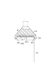
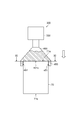
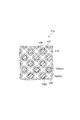
- (A) is a perspective view of the green honeycomb molded object which concerns on 1st Embodiment before sealing
- (b) is the elements on larger scale of (a).
- It is a perspective view which shows the sealing apparatus of the green honeycomb molded object which concerns on 1st Embodiment.
- It is a fragmentary sectional view of the closing jig for the entrance side of the green honeycomb molded object concerning a 1st embodiment.
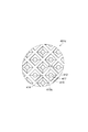
- It is the top view to which the part A of FIG. 3 was expanded.
- It is a fragmentary sectional view showing the initial state of the sealing process on the entrance side of the green honeycomb molded object concerning a 1st embodiment. It is sectional drawing by the VII-VII line of FIG.
- FIG. 13 is a cross-sectional view taken along line XIII-XIII in FIG. 12. It is a fragmentary sectional view which shows the state of the middle stage of the sealing process of FIG.
- FIG. 15 is a cross-sectional view taken along line XV-XV in FIG. 14.
- FIG. 7 is a cross-sectional view corresponding to a cross section taken along line VII-VII in FIG. 6 in a sealing step on the inlet side according to the second embodiment.
- FIG. 9 is a cross-sectional view corresponding to a cross section taken along line IX-IX of FIG. 8 in a sealing process on the inlet side according to the second embodiment.
- FIG. 11 is a cross-sectional view corresponding to a cross section taken along line XI-XI in FIG. 10 in a sealing process on the inlet side according to the second embodiment.
- FIG. 13 is a cross-sectional view corresponding to a cross section taken along line XIII-XIII in FIG. 12 in a sealing step on the outlet side according to the second embodiment.
- FIG. 15 is a cross-sectional view corresponding to a cross section taken along line XV-XV of FIG. 14 in a sealing step on the outlet side according to the second embodiment.
- FIG. 17 is a cross-sectional view corresponding to a cross section taken along line XVII-XVII in FIG. 16 in a sealing step on the outlet side according to the second embodiment.
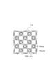
- the green honeycomb molded object 70 which concerns on this embodiment has the upper surface 71a, the lower surface 71b, and the side surface 71c, for example, and the upper surface 71a and the lower surface 71b are a plurality of octagonal through-holes. It is a cylindrical body in which an inlet-side octagonal cell 70Octin and an outlet-side square cell 70Sout which is a quadrangular through hole are opened.
- the entrance-side octagonal cell 70Octin and the exit-side quadrangular cell 70Sout extend substantially in parallel from the upper surface 71a to the lower surface 71b along the side surface 71c.
- the green honeycomb formed body 70 is an unfired formed body that becomes a porous ceramic when fired later.
- the length of the green honeycomb molded body 70 in the direction in which the inlet side octagonal cell 70Octin and the outlet side rectangular cell 70Sout extend is not particularly limited, but may be, for example, 40 to 400 mm.
- the outer diameter of the green honeycomb molded body 70 is not particularly limited, but may be, for example, 10 to 360 mm.
- the partition wall 70W allows the entrance-side octagonal cell 70Octin having a large opening area and the exit-side square cell 70Sout having an opening area smaller than that of the entrance-side octagonal cell 70Octin. And is divided.
- the entrance-side octagonal cell 70 Octin has an octagonal shape in which a square corner is further cut by a straight side.
- Four exit-side square cells 70Sout are adjacent to each other around one entrance-side octagonal cell 70Octin via four partition walls 70W that define four sides excluding the corners of the entrance-side octagon cell 70Octin. .
- inlet-side octagonal cells 70Octin are adjacent to each other around one outlet-side rectangular cell 70Sout via four partition walls 70W that define each side of the outlet-side rectangular cell 70Sout.
- the inlet-side octagonal cell 70Octin does not have to be a regular octagon, and the outlet-side rectangular cell 70Sout does not have to be square.
- the inlet-side octagonal cell 70Octin may have an octagonal shape that is long in one direction, and the outlet-side square cell 70Sout may have a rectangular shape.
- the inlet side octagonal cell 70Octin may be an octagonal shape in which the corners of the parallelogram are cut off at the right side, and the outlet side rectangular cell 70Sout may be a parallelogram shape.
- the external shape of the green honeycomb molded body 70 is not limited to a cylindrical body, but is an elliptical column or a rectangular column (for example, a regular polygonal column such as a triangular column, a quadrangular column, a hexagonal column, or an octagonal column, a triangular column other than a regular polygonal column, or a rectangular column.
- a regular polygonal column such as a triangular column, a quadrangular column, a hexagonal column, or an octagonal column, a triangular column other than a regular polygonal column, or a rectangular column.
- a case where the green honeycomb molded body 70 is a cylindrical body will be described.
- Such a green honeycomb molded body 70 is manufactured by extruding a ceramic composition with an extruder.
- a ceramic composition an inorganic compound source powder that is a ceramic raw material, an organic binder, a solvent, and an additive that is added as necessary are prepared.
- the inorganic compound source powder includes two or more selected from the group consisting of aluminum source powder, magnesium source powder, silicon source powder and titanium source powder, or silicon carbide source powder, silicon nitride source powder and aluminum nitride What contains any 1 type or more among source powders is mentioned.
- any one or more of a carbon source powder, a zirconium source powder, a molybdenum source powder, and a calcium source powder may be added to the inorganic compound source powder.
- aluminum source powder, magnesium source powder, titanium source powder and silicon source powder are included, heat resistance can be improved.
- organic binder examples include celluloses such as methylcellulose, carboxymethylcellulose, hydroxyalkylmethylcellulose, and sodium carboxymethylcellulose; alcohols such as polyvinyl alcohol; and lignin sulfonate.
- the additive include a pore-forming agent, a lubricant and a plasticizer, a dispersant, and a solvent.
- the prepared raw material is mixed by a kneader or the like to obtain a raw material mixture, and the obtained raw material mixture is extruded from an extruder having an outlet opening corresponding to the cross-sectional shape of the partition wall 70W, thereby forming the green honeycomb according to the present embodiment.
- the body is manufactured.
- the ultrasonic sealing machine 300 of this embodiment includes an ultrasonic signal transmitter 310, an ultrasonic transducer unit 320, a horn unit 330, and a sealing jig 400. Similar to the ultrasonic cutting machine 200 described above, the ultrasonic signal transmitter 310 transmits an electrical ultrasonic signal.
- the ultrasonic transducer unit 320 converts the electrical ultrasonic signal supplied from the ultrasonic signal transmitter 310 into mechanical ultrasonic vibration.
- the horn unit 330 amplifies the amplitude of the ultrasonic vibration supplied from the ultrasonic transducer unit 220.
- the sealing jig 400 is vibrated at a frequency of about 20 to 40 kHz by ultrasonic vibration supplied from the horn unit 330.
- sealing jig of this embodiment will be described.
- the sealing is performed in the same manner on both end faces of the green honeycomb molded body 70 having the inlet side octagonal cell 70Octin and the outlet side rectangular cell 70Sout.
- a sealing jig for sealing the upper surface 71a on the exhaust gas supply side (inlet side) when the green honeycomb molded body 70 is used as a particulate matter removing filter such as a diesel particulate filter after firing will be described.
- the sealing jig 400 of the present embodiment includes a sealing surface 401 a for sealing the green honeycomb molded body 70 and a support socket portion in which an end of the green honeycomb molded body 70 is fitted. 450.
- the sealing surface 401a is disposed at a position corresponding to the inlet-side octagonal cell 70Octin and inserted into the inlet-side octagonal cell 70Octin to weld the partition walls 70W to seal the outlet-side square cell 70Sout.
- the support socket portion 450 is formed of a cylindrical concave portion corresponding to the diameter of the green honeycomb molded body 70 to be sealed.
- the inner peripheral surface of the support socket portion 450 is provided with an inclined surface 451 such that the inner diameter of the support socket portion 450 increases as the distance from the sealing surface 401a increases so that the end of the green honeycomb molded body 70 can be easily inserted.
- the sealing jig 400 of the present embodiment is the same as the sealing jig 40 of the sealing jig 40 of the first embodiment.
- 401c has a sealing projection 410c.
- the sealing projection 410 c has a quadrangular pyramid base 416 and a conical tip 412.
- the quadrangular pyramidal base 416 is located at the base of the sealing projection 410c and protrudes from the sealing surface 401c.
- the quadrangular pyramid base portion 416 has a quadrangular pyramid shape obtained by removing a quadrangular pyramid that is similarly reduced from a quadrangular pyramid having a larger apex angle than the conical tip portion 412.
- the conical tip 412 is located at the top of the quadrangular pyramid base 416, which is the tip of the sealing projection 410c.
- the conical tip portion 412 has a conical shape having a bottom surface corresponding to the upper surface of the quadrangular pyramid base portion 416.
- the apex angle of the conical tip 412 is smaller than the apex angle formed by the sides of the quadrangular pyramid of the quadrangular pyramid base 416.
- the quadrangular pyramid base 416 includes a quadrangular pyramid side portion 417 on the side of the quadrangular pyramid and a round chamfered side portion 415 on the side of the quadrangular pyramid.
- the round chamfered side portion 415 is rounded with a predetermined curvature on each side of the quadrangular pyramid.
- the valley between the quadrangular pyramidal base portions 416 of the adjacent sealing projections 410c includes a round chamfered valley portion 414 that is a concave portion that is rounded with a predetermined curvature.
- each of the sealing protrusions 410 c is arranged such that the tops of the conical tip portions 412 correspond to the plurality of inlet side octagonal cells 70 Octin of the green honeycomb molded body 70. Further, each of the sealing projections 410c is arranged in such a direction that the rounded chamfered side portion 415 of the quadrangular pyramid base 416 contacts the partition wall 70W.
- the size of each of the quadrangular pyramidal base portions 416 is such that the length of the rounded chamfered side portion 415 projected from directly above the sealing surface 401c onto the sealing surface 401c is the center of the inlet-side octagonal cell 70Octin of the green honeycomb molded body 70. The size corresponds to the length of the center of the outlet side square cell 70Sout.
- a sealing jig 400 for sealing the lower surface 71b on the exhaust side (exit side) of exhaust gas Similar to the upper surface 71a, a sealing jig 400 having a sealing surface 401c in which a sealing projection 410c is arranged at a position corresponding to the outlet-side square cell 70Sout is used.
- the end on the upper surface 71 a side of the green honeycomb molded body 70 is inserted into the support socket portion 450 of the sealing jig 400 of the ultrasonic sealing machine 300.
- the sealing jig 400 is vibrated by ultrasonic vibration from the horn part 330.
- the tip of the sealing projection 410c on the sealing surface 401c is inserted into the inlet-side octagonal cell 70Octin.
- the conical tip portion 412 of the sealing projection 410c is inserted into the inlet-side octagonal cell 70Octin.
- the quadrangular pyramid base 416 of the sealing projection 410c is inserted into the inlet-side octagonal cell 70Octin as shown in FIG. Inserted.
- Each of the round chamfered side portions 415 of the quadrangular pyramid base 416 is brought into contact with the partition wall 70W. Since the sealing protrusion 410c is vibrated by ultrasonic vibration, the partition wall 70W is liquefied, and the sealing protrusion 410c at the center of the four inlet side octagonal cells 70Octin into which the sealing protrusions 410c are inserted is inserted.
- the outlet side square cell 70Sout is pressed to seal.
- the sealing step of the lower surface 71b that becomes the exhaust side (exit side) of the exhaust gas as shown in FIG.
- the end portion on the lower surface 71 b side of the green honeycomb molded body 70 is inserted into the support socket portion 450 of the sealing jig 400 of the ultrasonic sealing machine 300.
- the sealing jig 400 is vibrated by ultrasonic vibration from the horn part 330.
- the tip of the sealing projection 410c on the sealing surface 401c is inserted into the outlet-side square cell 70Sout.
- the conical tip portion 412 of the sealing projection 410c is inserted into the outlet side square cell 70Sout.
- the quadrangular pyramid base 416 of the sealing projection 410c is inserted into the outlet-side square cell 70Sout.
- the Each of the round chamfered side portions 415 of the quadrangular pyramid base 416 is brought into contact with the partition wall 70W. Since the sealing protrusion 410c is vibrated by ultrasonic vibration, the partition wall 70W is liquefied, and the sealing protrusion 410c at the center of the four outlet side square cells 70Sout into which the sealing protrusions 410c are inserted is not inserted.
- the inlet side octagonal cell 70Octin is pressed to seal.
- the sealing projection 410c when the sealing projection 410c is further inserted into the outlet side square cell 70Sout, the rounded chamfered side portion 415 and the quadrangular pyramid side surface portion 417 of the quadrangular pyramid base portion 416 are used as shown in FIG.
- the partition walls 70W pressed from four directions while being liquefied are welded together.
- the end of the welded partition wall 70 ⁇ / b> W is brought into contact with the round chamfered valley portion 414 of the sealing surface 401 c, and the rounded partition wall junction end portion 73 is formed in a state where the round chamfering corresponding to the shape of the round chamfered valley portion 414 is made.
- the sealing is completed.
- a plurality of inlet-side octagonal cells 70Octin and outlet-side square cells 70Sout which are partitioned by partition walls 70W, are opened on the upper surface 71a and the lower surface 71b of the column body, and fired.
- the partition walls 70W of the green honeycomb molded body 70 to be the honeycomb structure are joined to each other at the upper surface 71a and the lower surface 71b, thereby sealing the inlet side octagonal cell 70Octin or the outlet side rectangular cell 70Sout.
- the sealing paste as in the conventional method becomes unnecessary.
- the inlet and outlet of the exhaust gas flow channel at the end face are provided with through holes. Since it can be made larger than the opening area, the disturbance of the flow of the exhaust gas at the end face on the exhaust gas supply side is reduced, and the pressure loss can be reduced.
- FIG. 18 (a) when the outlet side square cell 70Sout is sealed by the conventional sealing material 70P, there is a drawback that the air resistance is large on the upper surface 71a on the exhaust gas supply side (inlet side).
- FIG. 18 (a) when the outlet side square cell 70Sout is sealed by the conventional sealing material 70P, there is a drawback that the air resistance is large on the upper surface 71a on the exhaust gas supply side (inlet side).
- the green honeycomb molded body 70 in which a part of the through-hole is sealed is formed such that, on the upper surface 71a or the lower surface 71b, one inlet side octagonal cell 70Octin and one inlet side octagonal cell 70Octin are surrounded by a partition wall 70W.
- four exit-side square cells 70Sout having an opening area smaller than that of the adjacent entrance-side octagonal cell 70Octin. For this reason, for example, when the honeycomb structure is applied to a particulate matter removing filter such as a diesel particulate filter, the outlet side square cell 70Sout having a small opening area is sealed on the inlet side of the particulate matter removing filter and the opening area is large.
- the inlet side becomes wider and soot accumulates. It is also possible to reduce the pressure loss in the wet state.
- the through-hole having a large opening area is the inlet-side octagonal cell 70 Octin
- the through-hole having a small opening area adjacent to the periphery of the inlet-side octagonal cell 70 Octin is the outlet-side square cell 70 Sout.
- through-side square cells 70Sout are adjacent to every other side of the inlet-side octagonal cell 70Octin, through holes having different sizes can be arranged on the upper surface 71a or the lower surface 71b.
- the outlet side square cell 70Sout is sealed at the upper surface 71a, and the inlet side octagonal cell 70Octin is sealed at the lower surface 71b. For this reason, for example, when the honeycomb structure is applied to a particulate matter removing filter such as a diesel particulate filter, the outlet side square cell 70Sout having a small opening area is sealed on the inlet side of the particulate matter removing filter and the opening area is large.
- the inlet side becomes wider and soot accumulates. It is also possible to reduce the pressure loss in the wet state.
- the sealing protrusions 410c of the sealing jig 400 into the plurality of inlet side octagonal cells 70Octin or outlet side rectangular cells 70Sout of the green honeycomb molded body 70, the partition walls 70W are joined to each other by the upper surface 71a or the lower surface 71b. And seal the cell. Thereby, sealing of a cell can be performed very easily.
- the rounding chamfered side portion 415 includes the sealing projection 410c of the sealing jig 400 including either a quadrangular pyramid or a quadrangular pyramid shape on the inlet side octagonal cell 70Octin.
- the outlet side square cell 70Sout is sealed by inserting the rounded chamfered side portion 415 so as to be in contact with each of the partition walls 70W adjacent to each other. Thereby, the exit side square cell 70Sout can be easily and reliably sealed.
- the sealing protrusion 410c of the sealing jig 400 including either a quadrangular pyramid or a quadrangular pyramid shape is provided in each of the through holes of the outlet-side rectangular cell 70Sout.
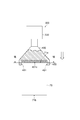
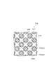
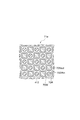
- the green honeycomb molded body 70 has, for example, an upper surface 71a, a lower surface 71b, and a side surface 71c, and a plurality of square corners are rounded on the upper surface 71a and the lower surface 71b. It is a cylindrical body in which an entrance-side rounded quadrangular cell 70SRin which is a rounded quadrangular through-hole and an outlet-side quadrangular cell 70Sout which is a quadrangular through-hole similar to the first embodiment are opened. .
- the entrance-side rounded quadrangular cell 70SRin and the exit-side quadrangular cell 70Sout extend substantially in parallel from the upper surface 71a to the lower surface 71b along the side surface 71c.
- the green honeycomb molded body 70 is an unfired molded body that becomes a porous ceramic when fired later, and the materials and manufacturing methods other than the entrance-side rounded square cell 70SRin are the same. is there.
- the length of the green honeycomb molded body 70 in the direction in which the entrance-side rounded square cell 70SRin and the outlet-side square cell 70Sout extend is not particularly limited, but may be, for example, 40 to 400 mm.
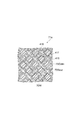
- the partition wall 70W allows the entrance-side rounded square cell 70SRin having a large opening area and the exit-side square having an opening area smaller than the entrance-side rounded square cell 70SRin.
- a cell 70Sout is partitioned.
- the entrance-side rounded quadrangular cell 70SRin has a rounded quadrangular shape with rounded chamfered corners.
- Four exit-side square cells 70Sout are adjacent to each other around one entrance-side rounded quadrangular cell 70SRin via four partition walls 70W that define four sides of the entrance-side rounded quadrangular cell 70SRin.
- the entrance-side square cells 70SRin are adjacent to each other around one exit-side square cell 70Sout via four partition walls 70W that define each side of the exit-side square cell 70Sout.
- the entrance-side rounded quadrangular cell 70SRin does not have to have a rounded corner.
- the entrance-side rounded square cell 70SRin may have a rounded square shape that is long in one direction.
- the entrance-side rounded quadrangular cell 70SRin may have a rounded quadrangular shape in which the corners of the parallelogram are rounded.
- the sealing step of the green honeycomb molded body 70 of the present embodiment will be described.
- the inlet-side rounded square cell 70SRin and the outlet-side rectangular cell 70Sout are sealed using the same sealing jig 400 as in the first embodiment.
- the sealing step of the upper surface 71a on the exhaust gas supply side (inlet side) when the green honeycomb molded body 70 is used as a particulate matter removal filter such as a diesel particle filter after firing will be described.
- the end on the upper surface 71 a side of the green honeycomb molded body 70 is inserted into the support socket portion 450 of the sealing jig 400 of the ultrasonic sealing machine 300.
- the sealing jig 400 is vibrated by ultrasonic vibration from the horn part 330.
- the tip of the sealing projection 410c on the sealing surface 401c is inserted into the inlet-side rounded quadrangular cell 70SRin.
- the conical tip portion 412 of the sealing projection 410c is inserted into the entrance-side rounded square cell 70SRin.
- the quadrangular pyramid base 416 of the sealing projection 410c becomes the entrance-side rounded quadrangular cell. 70SRin.
- Each of the round chamfered side portions 415 of the quadrangular pyramid base 416 is brought into contact with the partition wall 70W. Since the sealing projection 410c is vibrated by ultrasonic vibration, the partition wall 70W is liquefied and the sealing projection 410c at the center of each of the four entrance-side rounded square cells 70SRin into which the sealing projections 410c are inserted is inserted.
- the outlet-side square cell 70Sout that is not closed is pressed to seal.
- the sealing projection 410c when the sealing projection 410c is further inserted into the entrance-side rounded quadrangular cell 70SRin, as shown in FIG. 22, the rounded chamfered side portion 415 and the quadrangular pyramid side portion of the quadrangular pyramid base portion 416
- the partition walls 70W pressed from four directions while being liquefied by 417 are welded together.
- the end of the welded partition wall 70 ⁇ / b> W is brought into contact with the round chamfered valley portion 414 of the sealing surface 401 c, and the rounded partition wall junction end portion 73 is formed in a state where the round chamfering corresponding to the shape of the round chamfered valley portion 414 is made.
- the sealing is completed.
- the sealing step of the lower surface 71b that becomes the exhaust side (exit side) of the exhaust gas as shown in FIG.
- the end portion on the lower surface 71 b side of the green honeycomb molded body 70 is inserted into the support socket portion 450 of the sealing jig 400 of the ultrasonic sealing machine 300.
- the sealing jig 400 is vibrated by ultrasonic vibration from the horn part 330.
- the tip of the sealing projection 410c on the sealing surface 401c is inserted into the outlet-side square cell 70Sout.
- the conical tip portion 412 of the sealing projection 410c is inserted into the outlet-side square cell 70Sout.
- the quadrangular pyramid base 416 of the sealing projection 410c is inserted into the outlet-side square cell 70Sout.
- the Each of the round chamfered side portions 415 of the quadrangular pyramid base 416 is brought into contact with the partition wall 70W. Since the sealing protrusion 410c is vibrated by ultrasonic vibration, the partition wall 70W is liquefied, and the sealing protrusion 410c at the center of the four outlet side square cells 70Sout into which the sealing protrusions 410c are inserted is not inserted.
- the inlet side rounded square cell 70SRin is pressed to seal.
- the through-hole having a large opening area is the entrance-side rounded square cell 70SRin
- the through-hole having a small opening area adjacent to the periphery of the entrance-side rounded square cell 70SRin is the exit-side square cell 70Sout. . Therefore, through-side square cells 70Sout are adjacent to every other side of the entrance-side rounded square cell 70SRin, through holes having different sizes can be arranged on the upper surface 71a or the lower surface 71b.
- the sealed green honeycomb molded body 70 is sealed by welding the partition walls 70W by applying ultrasonic waves, but the sealed green honeycomb molded body 70 is It is not limited to an aspect.
- the sealed green honeycomb molded body 70 includes those sealed by crimping the partition walls 70 ⁇ / b> W without application of ultrasonic waves.
- the sealed green honeycomb molded body 70 includes those sealed by pressure-bonding the partition walls 70 ⁇ / b> W by applying a vibration having a frequency lower than that of ultrasonic waves, for example, 1 kHz or less.
- a manufacturing method capable of easily sealing an end portion of the honeycomb structure without using a sealing paste, and a honeycomb structure manufactured thereby. I can do it.
Landscapes
- Engineering & Computer Science (AREA)
- Chemical & Material Sciences (AREA)
- Ceramic Engineering (AREA)
- Mechanical Engineering (AREA)
- Manufacturing & Machinery (AREA)
- Chemical Kinetics & Catalysis (AREA)
- Structural Engineering (AREA)
- Filtering Materials (AREA)
- Physics & Mathematics (AREA)
- Geometry (AREA)
- Devices For Post-Treatments, Processing, Supply, Discharge, And Other Processes (AREA)
- Filtering Of Dispersed Particles In Gases (AREA)
Abstract
Description
(グリーンハニカム成形体(八角形セル及び四角形セル))
まず、本発明の第1実施形態において加工の対象となるグリーンハニカム成形体について説明する。図1(a)に示すように、本実施形態に係るグリーンハニカム成形体70は、例えば、上面71a、下面71b及び側面71cを有し、上面71a及び下面71bに複数の八角形状の貫通孔である入口側八角形セル70Octinと、四角形状の貫通孔である出口側四角形セル70Soutとが開口している円柱体である。入口側八角形セル70Octinと出口側四角形セル70Soutとは、側面71cに沿って上面71aから下面71bまで略平行に伸びている。グリーンハニカム成形体70は、後で焼成することにより多孔質のセラミックとなる未焼成成形体である。また、グリーンハニカム成形体70の入口側八角形セル70Octinと出口側四角形セル70Soutとが延びる方向の長さは特に限定されないが、例えば、40~400mmとすることができる。また、グリーンハニカム成形体70の外径も特に限定されないが、例えば、10~360mmとすることできる。
以下、本実施形態の超音波封口機について説明する。図2に示すように、本実施形態の超音波封口機300は、超音波信号発信器310、超音波振動子部320、ホーン部330及び封口用治具400を備える。上記の超音波切断機200と同様に、超音波信号発信器310は、電気的な超音波信号を発信する。超音波振動子部320は、超音波信号発信器310から供給された電気的な超音波信号を機械的な超音波振動に変換する。ホーン部330は、超音波振動子部220から供給された超音波振動の振幅を増幅する。封口用治具400はホーン部330から供給された超音波振動により、20~40kHz程度の周波数で振動させられる。
以下、本実施形態の封口用治具について説明する。本実施形態では、入口側八角形セル70Octin及び出口側四角形セル70Soutを有するグリーンハニカム成形体70の両端面で同様の態様で封口を行う。まず、グリーンハニカム成形体70を焼成後にディーゼル粒子フィルタ等の粒子状物質除去フィルタとした場合に、排ガスの供給側(入口側)となる上面71aを封口するための封口用治具について説明する。
以下、本実施形態のグリーンハニカム成形体70の封口工程について説明する。まず、グリーンハニカム成形体70を焼成後にディーゼル粒子フィルタ等の粒子状物質除去フィルタとした場合に、排ガスの供給側(入口側)となる上面71aの封口工程について説明する。
(グリーンハニカム成形体(角丸四角形セル及び四角形セル))
まず、本発明の第2実施形態において加工の対象となるグリーンハニカム成形体について説明する。図19(a)に示すように、本実施形態に係るグリーンハニカム成形体70は、例えば、上面71a、下面71b及び側面71cを有し、上面71a及び下面71bに複数の四角形の角部が丸められた角丸四角形状の貫通孔である入口側角丸四角形セル70SRinと、上記第1実施形態と同様の四角形状の貫通孔である出口側四角形セル70Soutとが開口している円柱体である。入口側角丸四角形セル70SRinと出口側四角形セル70Soutとは、側面71cに沿って上面71aから下面71bまで略平行に伸びている。上記第1実施形態と同様に、グリーンハニカム成形体70は、後で焼成することにより多孔質のセラミックとなる未焼成成形体であり、入口側角丸四角形セル70SRin以外の材質や製法は同様である。また、グリーンハニカム成形体70の入口側角丸四角形セル70SRinと出口側四角形セル70Soutとが延びる方向の長さは特に限定されないが、例えば、40~400mmとすることができる。
以下、本実施形態のグリーンハニカム成形体70の封口工程について説明する。本実施形態においては、上記第1実施形態と同様の封口用治具400を用いて入口側角丸四角形セル70SRin及び出口側四角形セル70Soutの封口が行われる。まず、グリーンハニカム成形体70を焼成後にディーゼル粒子フィルタ等の粒子状物質除去フィルタとした場合に、排ガスの供給側(入口側)となる上面71aの封口工程について説明する。
Claims (8)
- 柱体の端面で開口し互いに隔壁で区画された複数の貫通孔の一部が封口されたハニカム構造体の製造方法であって、
グリーンハニカム成形体の前記隔壁同士を前記端面で接合することにより前記貫通孔の一部を封口する封口工程を備え、
前記封口工程で前記貫通孔の一部を封口される前記グリーンハニカム成形体は、
前記端面において、1つの第1の前記貫通孔と、1つの第1の前記貫通孔の周囲に前記隔壁を介して隣接した第1の前記貫通孔よりも小さい開口面積を有する4つの第2の前記貫通孔とを有する、ハニカム構造体の製造方法。 - 第1の前記貫通孔は八角形状であり、第2の前記貫通孔は四角形状である、請求項1に記載のハニカム構造体の製造方法。
- 第1の前記貫通孔は四角形の角部が丸められた角丸四角形状であり、第2の前記貫通孔は四角形状である、請求項1に記載のハニカム構造体の製造方法。
- 前記封口工程では、一方の前記端面において、第2の前記貫通孔を封口し、他方の前記端面において、第1の前記貫通孔を封口する、請求項1~3のいずれか1項に記載のハニカム構造体の製造方法。
- 前記封口工程では、前記グリーンハニカム成形体の複数の前記貫通孔の一部に封口用治具を挿入することにより、前記隔壁同士を前記端面で接合して前記貫通孔を封口する、請求項1~4のいずれか1項に記載のハニカム構造体の製造方法。
- 前記封口工程では、第2の前記貫通孔の封口において、第1の前記貫通孔に四角錐及び四角錐台のいずれかの形状を含む前記封口用治具をその側辺が第2の前記貫通孔に隣接した前記隔壁それぞれに当接するようにしつつ挿入することにより、第2の前記貫通孔を封口する、請求項5に記載のハニカム構造体の製造方法。
- 前記封口工程では、第1の前記貫通孔の封口において、第2の前記貫通孔それぞれに四角錐及び四角錐台のいずれかの形状を含む前記封口用治具をその側辺が第1の前記貫通孔に隣接した前記隔壁に当接するようにしつつ挿入することにより、第1の前記貫通孔を封口する、請求項5又は6に記載のハニカム構造体の製造方法。
- 請求項1~7のいずれか1項記載の方法により製造されたハニカム構造体。
Priority Applications (6)
| Application Number | Priority Date | Filing Date | Title |
|---|---|---|---|
| MX2015017477A MX2015017477A (es) | 2013-06-28 | 2014-05-30 | Metodo para producir estructuras alveolares. |
| US14/392,179 US20160185010A1 (en) | 2013-06-28 | 2014-05-30 | Method for producing honeycomb structures |
| EP14817867.6A EP3015234A4 (en) | 2013-06-28 | 2014-05-30 | Method for producing honeycomb structures |
| KR1020157037092A KR20160025529A (ko) | 2013-06-28 | 2014-05-30 | 허니콤 구조체의 제조 방법 |
| CN201480034600.8A CN105324224A (zh) | 2013-06-28 | 2014-05-30 | 蜂窝构造体的制造方法 |
| US15/095,664 US9700820B2 (en) | 2013-06-28 | 2016-04-11 | Method for producing honeycomb structures |
Applications Claiming Priority (2)
| Application Number | Priority Date | Filing Date | Title |
|---|---|---|---|
| JP2013-136587 | 2013-06-28 | ||
| JP2013136587A JP6140554B2 (ja) | 2013-06-28 | 2013-06-28 | ハニカム構造体の製造方法 |
Related Child Applications (2)
| Application Number | Title | Priority Date | Filing Date |
|---|---|---|---|
| US14/392,179 A-371-Of-International US20160185010A1 (en) | 2013-06-28 | 2014-05-30 | Method for producing honeycomb structures |
| US15/095,664 Continuation US9700820B2 (en) | 2013-06-28 | 2016-04-11 | Method for producing honeycomb structures |
Publications (1)
| Publication Number | Publication Date |
|---|---|
| WO2014208275A1 true WO2014208275A1 (ja) | 2014-12-31 |
Family
ID=52141626
Family Applications (1)
| Application Number | Title | Priority Date | Filing Date |
|---|---|---|---|
| PCT/JP2014/064504 WO2014208275A1 (ja) | 2013-06-28 | 2014-05-30 | ハニカム構造体の製造方法 |
Country Status (7)
| Country | Link |
|---|---|
| US (2) | US20160185010A1 (ja) |
| EP (1) | EP3015234A4 (ja) |
| JP (1) | JP6140554B2 (ja) |
| KR (1) | KR20160025529A (ja) |
| CN (1) | CN105324224A (ja) |
| MX (1) | MX2015017477A (ja) |
| WO (1) | WO2014208275A1 (ja) |
Families Citing this family (2)
| Publication number | Priority date | Publication date | Assignee | Title |
|---|---|---|---|---|
| JP6216797B2 (ja) * | 2012-10-19 | 2017-10-18 | ダウ グローバル テクノロジーズ エルエルシー | 形成可能および/または崩壊し得る材料を切断するための器具、および方法 |
| CN109209575B (zh) | 2018-09-29 | 2021-05-14 | 大连理工大学 | 一种颗粒捕集器过滤体的非对称孔道结构 |
Citations (4)
| Publication number | Priority date | Publication date | Assignee | Title |
|---|---|---|---|---|
| JPS6324731B2 (ja) | 1980-06-16 | 1988-05-23 | Ngk Insulators Ltd | |
| JP2004042440A (ja) * | 2001-08-28 | 2004-02-12 | Denso Corp | 排ガス浄化フィルタ及びその製造方法 |
| JP2006272318A (ja) * | 2005-03-01 | 2006-10-12 | Denso Corp | 排ガス浄化フィルタの製造方法 |
| WO2014103839A1 (ja) * | 2012-12-27 | 2014-07-03 | 住友化学株式会社 | ハニカム構造体の製造方法 |
Family Cites Families (13)
| Publication number | Priority date | Publication date | Assignee | Title |
|---|---|---|---|---|
| JPS577215B2 (ja) | 1974-01-28 | 1982-02-09 | ||
| JPS577217A (en) * | 1980-06-16 | 1982-01-14 | Ngk Insulators Ltd | Ceramic honeycomb filter and preparation thereof |
| JPS6324731A (ja) | 1986-07-17 | 1988-02-02 | Fujitsu Ltd | デ−タ伝送回路 |
| DE4224726A1 (de) | 1992-07-27 | 1994-02-03 | Voith Gmbh J M | Streicheinrichtung mit zwischen einer Auftragswalze und einer Gegenwalze gebildetem Auftragsspalt |
| DK40293D0 (da) * | 1993-04-05 | 1993-04-05 | Per Stobbe | Method for preparing a filter body |
| JP3719232B2 (ja) * | 2002-06-18 | 2005-11-24 | トヨタ自動車株式会社 | 内燃機関のパティキュレートフィルタ |
| JP4032902B2 (ja) * | 2002-09-25 | 2008-01-16 | トヨタ自動車株式会社 | 排気浄化用の基材、および、その製造方法 |
| JP2004321848A (ja) | 2003-04-21 | 2004-11-18 | Ngk Insulators Ltd | ハニカム構造体及びその製造方法 |
| JP3945452B2 (ja) * | 2003-05-30 | 2007-07-18 | 株式会社デンソー | 排ガス浄化フィルタの製造方法 |
| KR100679190B1 (ko) * | 2003-06-23 | 2007-02-06 | 이비덴 가부시키가이샤 | 벌집형 구조체 |
| JP4767491B2 (ja) * | 2003-12-11 | 2011-09-07 | 日本碍子株式会社 | ハニカム構造体 |
| JP5124177B2 (ja) * | 2007-06-13 | 2013-01-23 | 東京窯業株式会社 | ハニカム構造体 |
| KR101569330B1 (ko) * | 2012-10-15 | 2015-11-13 | 스미또모 가가꾸 가부시끼가이샤 | 허니컴 구조체의 제조 방법 및 그린 허니컴 성형품용 실링 지그 |
-
2013
- 2013-06-28 JP JP2013136587A patent/JP6140554B2/ja active Active
-
2014
- 2014-05-30 EP EP14817867.6A patent/EP3015234A4/en not_active Withdrawn
- 2014-05-30 CN CN201480034600.8A patent/CN105324224A/zh active Pending
- 2014-05-30 WO PCT/JP2014/064504 patent/WO2014208275A1/ja active Application Filing
- 2014-05-30 US US14/392,179 patent/US20160185010A1/en not_active Abandoned
- 2014-05-30 KR KR1020157037092A patent/KR20160025529A/ko not_active Application Discontinuation
- 2014-05-30 MX MX2015017477A patent/MX2015017477A/es unknown
-
2016
- 2016-04-11 US US15/095,664 patent/US9700820B2/en active Active
Patent Citations (4)
| Publication number | Priority date | Publication date | Assignee | Title |
|---|---|---|---|---|
| JPS6324731B2 (ja) | 1980-06-16 | 1988-05-23 | Ngk Insulators Ltd | |
| JP2004042440A (ja) * | 2001-08-28 | 2004-02-12 | Denso Corp | 排ガス浄化フィルタ及びその製造方法 |
| JP2006272318A (ja) * | 2005-03-01 | 2006-10-12 | Denso Corp | 排ガス浄化フィルタの製造方法 |
| WO2014103839A1 (ja) * | 2012-12-27 | 2014-07-03 | 住友化学株式会社 | ハニカム構造体の製造方法 |
Non-Patent Citations (1)
| Title |
|---|
| See also references of EP3015234A4 |
Also Published As
| Publication number | Publication date |
|---|---|
| US9700820B2 (en) | 2017-07-11 |
| EP3015234A4 (en) | 2017-05-10 |
| MX2015017477A (es) | 2016-03-31 |
| US20160263507A1 (en) | 2016-09-15 |
| US20160185010A1 (en) | 2016-06-30 |
| CN105324224A (zh) | 2016-02-10 |
| JP2015009444A (ja) | 2015-01-19 |
| KR20160025529A (ko) | 2016-03-08 |
| JP6140554B2 (ja) | 2017-05-31 |
| EP3015234A1 (en) | 2016-05-04 |
Similar Documents
| Publication | Publication Date | Title |
|---|---|---|
| JP5636524B2 (ja) | グリーンハニカム成形体の封口用治具及びハニカム構造体の製造方法 | |
| JP6596413B2 (ja) | ハニカムフィルタ、及び、ハニカムフィルタの製造方法 | |
| JP5677648B2 (ja) | ハニカム構造体の製造方法 | |
| WO2016098835A1 (ja) | ハニカム構造体 | |
| WO2014208275A1 (ja) | ハニカム構造体の製造方法 | |
| JP5416636B2 (ja) | 目封止ハニカム構造体の製造方法 | |
| JP6155139B2 (ja) | ハニカム構造体の製造方法、治具及びハニカム構造体 | |
| JP5636525B2 (ja) | ハニカム構造体の製造方法 | |
| WO2014208276A1 (ja) | ハニカム構造体の製造方法及びグリーンハニカム成形体の封口用治具 | |
| JP2014141062A (ja) | ハニカム構造体の製造方法 | |
| JP2015009441A (ja) | ハニカム構造体の製造方法 | |
| JP2014141063A (ja) | ハニカム構造体の製造方法、グリーンハニカム成形体の加工装置及びハニカム構造体 | |
| JP2013154549A (ja) | ハニカム構造体の封口方法 | |
| JP2006272156A (ja) | ハニカムフィルタ |
Legal Events
| Date | Code | Title | Description |
|---|---|---|---|
| WWE | Wipo information: entry into national phase |
Ref document number: 201480034600.8 Country of ref document: CN |
|
| 121 | Ep: the epo has been informed by wipo that ep was designated in this application |
Ref document number: 14817867 Country of ref document: EP Kind code of ref document: A1 |
|
| WWE | Wipo information: entry into national phase |
Ref document number: MX/A/2015/017477 Country of ref document: MX |
|
| WWE | Wipo information: entry into national phase |
Ref document number: 14392179 Country of ref document: US Ref document number: 2014817867 Country of ref document: EP |
|
| NENP | Non-entry into the national phase |
Ref country code: DE |
|
| ENP | Entry into the national phase |
Ref document number: 20157037092 Country of ref document: KR Kind code of ref document: A |