WO2014208110A1 - アキシャル型回転電機 - Google Patents
アキシャル型回転電機 Download PDFInfo
- Publication number
- WO2014208110A1 WO2014208110A1 PCT/JP2014/051193 JP2014051193W WO2014208110A1 WO 2014208110 A1 WO2014208110 A1 WO 2014208110A1 JP 2014051193 W JP2014051193 W JP 2014051193W WO 2014208110 A1 WO2014208110 A1 WO 2014208110A1
- Authority
- WO
- WIPO (PCT)
- Prior art keywords
- permanent magnet
- yoke
- rotor
- axial
- support member
- Prior art date
Links
Images


Classifications
-
- H—ELECTRICITY
- H02—GENERATION; CONVERSION OR DISTRIBUTION OF ELECTRIC POWER
- H02K—DYNAMO-ELECTRIC MACHINES
- H02K1/00—Details of the magnetic circuit
- H02K1/06—Details of the magnetic circuit characterised by the shape, form or construction
- H02K1/22—Rotating parts of the magnetic circuit
- H02K1/27—Rotor cores with permanent magnets
- H02K1/2793—Rotors axially facing stators
- H02K1/2795—Rotors axially facing stators the rotor consisting of two or more circumferentially positioned magnets
-
- H—ELECTRICITY
- H02—GENERATION; CONVERSION OR DISTRIBUTION OF ELECTRIC POWER
- H02K—DYNAMO-ELECTRIC MACHINES
- H02K1/00—Details of the magnetic circuit
- H02K1/02—Details of the magnetic circuit characterised by the magnetic material
-
- H—ELECTRICITY
- H02—GENERATION; CONVERSION OR DISTRIBUTION OF ELECTRIC POWER
- H02K—DYNAMO-ELECTRIC MACHINES
- H02K1/00—Details of the magnetic circuit
- H02K1/06—Details of the magnetic circuit characterised by the shape, form or construction
- H02K1/22—Rotating parts of the magnetic circuit
- H02K1/27—Rotor cores with permanent magnets
- H02K1/2793—Rotors axially facing stators
- H02K1/2795—Rotors axially facing stators the rotor consisting of two or more circumferentially positioned magnets
- H02K1/2798—Rotors axially facing stators the rotor consisting of two or more circumferentially positioned magnets where both axial sides of the stator face a rotor
-
- H—ELECTRICITY
- H02—GENERATION; CONVERSION OR DISTRIBUTION OF ELECTRIC POWER
- H02K—DYNAMO-ELECTRIC MACHINES
- H02K21/00—Synchronous motors having permanent magnets; Synchronous generators having permanent magnets
- H02K21/12—Synchronous motors having permanent magnets; Synchronous generators having permanent magnets with stationary armatures and rotating magnets
- H02K21/24—Synchronous motors having permanent magnets; Synchronous generators having permanent magnets with stationary armatures and rotating magnets with magnets axially facing the armatures, e.g. hub-type cycle dynamos
-
- H—ELECTRICITY
- H02—GENERATION; CONVERSION OR DISTRIBUTION OF ELECTRIC POWER
- H02K—DYNAMO-ELECTRIC MACHINES
- H02K2213/00—Specific aspects, not otherwise provided for and not covered by codes H02K2201/00 - H02K2211/00
- H02K2213/03—Machines characterised by numerical values, ranges, mathematical expressions or similar information
Definitions
- the present invention relates to a rotor capable of improving torque and efficiency with respect to the size of the rotor, and an axial-type electric rotating machine using the rotor.
- the rotating electric machine has a structure in which a disk-shaped rotor and a stator are disposed to face each other, and is an advantageous configuration for thinning and flattening of the rotating electric machine. Further, in the present rotating electrical machine, it is also possible to configure the stator with a double rotor type in which the two rotors are sandwiched in the axial direction.
- a typical double-rotor type rotary electric machine has a stator in which a plurality of winding cores wound around an independent core are disposed in the circumferential direction, and a resin-molded stator and a plurality of circumferentially disposed permanent magnets in the yoke It consists of a connected rotor.
- the torque of the motor is proportional to the gap area which is the opposing surface of the rotor and the stator, but the double rotor type can increase the gap area per body size, which is effective for increasing the output and efficiency of the rotating electrical machine .
- the authors consider this to be an effective structure for the application of amorphous metals characterized by low loss. Amorphous metals are difficult to process because they are hard and brittle.
- the double rotor type rotary electric machine can form the core in a very simple shape of substantially a rectangular parallelepiped. Therefore, it is possible to process the amorphous metal into the core shape by a simple method.
- an axial type rotating electrical machine in order to improve torque and efficiency, it is effective to enlarge the diameter and increase the area (hereinafter, gap area) where the stator and the rotor face each other.
- gap area the area where the stator and the rotor face each other.
- care is required because this increases the centrifugal force acting on the rotor.
- a surface magnet type configuration in which permanent magnets are installed on the rotor surface is adopted, and scattering and breakage of magnets due to centrifugal force become a problem.
- the rotors described in Patent Document 1 and Patent Document 2 are composed of permanent magnets and yokes, and a supporting member for holding them and fixing them to a shaft.
- a protrusion covering the outer peripheral surface of the permanent magnet is provided on the outer diameter side of the support member to improve the strength against centrifugal force.
- Such a rotor structure is commonly found in other inventions related to axial type rotating electrical machines.
- the present invention provides a rotor and an axial-type electric rotating machine using the rotor that can improve the torque and the efficiency with respect to the size of the rotor.
- a stator having a stator core and a rotor facing the stator along an axial direction of a rotation axis passing through the stator, the rotor facing the stator core in the axial direction of the rotation axis
- a permanent magnet disposed, a yoke disposed opposite to the stator core with the permanent magnet interposed therebetween, and a support member for supporting the yoke, the support member being a portion of the permanent magnet far from the rotation axis
- the projection When projected along the axial direction of the rotation axis, the projection has a first region in which the projection of the permanent magnet does not overlap with the projection of the yoke, 1)
- An axial-type electric rotating machine in which one area is formed on the outer diameter side of a permanent magnet and the first area is formed on the side of a protrusion.
- the rotor and the axial type rotating electric machine using the rotor according to the present invention can improve the torque and the efficiency with respect to the size of the rotor. Problems, configurations, and effects other than those described above will be apparent from the description of the embodiments below.
- FIG. 2 is a cross-sectional perspective view of an axial type rotary electric machine according to a first embodiment.
- FIG. 2 is a perspective view of an axial type rotary electric machine according to a first embodiment.
- FIG. 2 is an enlarged cross-sectional view of a rotor in Example 1;
- FIG. 7 is an enlarged cross-sectional view of a protrusion of a support member in Example 1;
- FIG. 6 is a view from the axial direction of the rotation axis of the permanent magnet and the yoke in the first embodiment.
- FIG. 7 is a cross-sectional perspective view of an axial type rotating electric machine in a second embodiment.
- FIG. 7 is an enlarged cross-sectional view of a rotor in a second embodiment.
- FIG. 10 is an enlarged cross-sectional view of a protrusion of a support member in Example 2;
- FIG. 10 is a cross-sectional perspective view of an axial type rotating electric machine in a third embodiment.
- FIG. 14 is an enlarged cross-sectional view of a rotor in Example 3; The figure from the axial direction of the rotating shaft of the permanent magnet in Example 3, and a yoke.
- FIG. 14 is a cross-sectional perspective view of an axial-type electric rotating machine in a fourth embodiment.
- FIG. 16 is a perspective view of an axial type rotating electric machine in a fourth embodiment. Sectional drawing of the axial type rotary electric machine in Example 4.
- FIG. FIG. 16 is an enlarged cross-sectional view of a rotor in Example 4; FIG.
- FIG. 18 is a view from the axial direction of the rotating shaft of the permanent magnet and the yoke in the fourth embodiment.
- the permanent magnet in Example 4 and the enlarged view of a stator core periphery.
- FIG. 16 is an enlarged cross-sectional view of a protrusion of a support member in Example 5; Sectional perspective view of the conventional axial type rotary electric machine. The expanded sectional view of the conventional rotor.
- FIG.6 (a) is a cross-sectional perspective view of the conventional axial type rotary electric machine
- FIG.6 (b) is an expanded sectional view of the conventional rotor. Descriptions of symbols in FIGS. 6 (a) and 6 (b) are described in the following examples.
- FIGS. 1 (a) to 1 (e) are diagrams for explaining an example in which the present invention is applied to a double rotor type axial motor having one stator and two rotors.
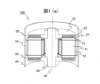
- FIG. 1 (a) is a cross-sectional perspective view of a motor (axial type rotary electric machine 100) in the present embodiment
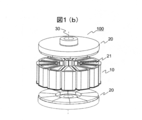
- FIG. 1 (b) is a perspective view of an axial type rotary electric machine in the present embodiment.
- the axial type rotating electric machine 100 of FIG. 1A includes a rotor 20 disposed via an air gap so as to sandwich the stator 10 from the direction of the rotating shaft 30 passing through the stator 10 and the stator 10; It comprises a housing 40 for holding the stator 10 and a shaft 50 for holding the rotor 20 via a bearing (not shown).
- the rotor 20 faces the stator 10 along the axial direction of the rotation shaft 30.
- the housing 40 and the shaft 50 are not shown in FIG. Also, the air gap is shown enlarged so that the structure of the stator 10 can be understood.
- the stator 10 includes a plurality of soft magnetic stator cores 11 arranged in the circumferential direction, a winding 12 wound around the stator core 11, and a bobbin electrically insulating the stator core 11 and the windings 12 from each other. 13).
- the stator core 11, the winding 12, and the bobbin 13 are molded integrally with the housing 40 with resin.
- the rotor 20 has a permanent magnet 21 disposed opposite to the axial end face of the stator core 11, a yoke 22 of a soft magnetic material disposed on the back of the permanent magnet 21, a permanent magnet 21 and a yoke 22 as a shaft 50. And a support member 23 for holding and supporting the yoke 22.
- the yoke 22 is disposed to face the stator core 11 with the permanent magnet 21 interposed therebetween.
- the support member 23 is fixed to the rotating shaft 30.
- FIG. 1 (c) is an enlarged cross-sectional view of the rotor in the present embodiment
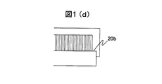
- FIG. 1 (d) is an enlarged cross-sectional view of the projection of the support member in the present embodiment.
- the support member 23 has a protrusion 23 c that protrudes so as to face the side surface 21 a of the permanent magnet 21 on the side far from the rotation shaft 30.
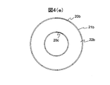
- the figure which looked at the permanent magnet and yoke from the axial direction of the rotating shaft in FIG.1 (e) is shown.
- the outer diameter of the permanent magnet 21 is larger than the outer diameter of the yoke 22 and has a first region 20 b which does not overlap with the yoke 22.
- the first region 20 b is formed on the outer diameter side of the permanent magnet 21.
- the permanent magnet 21 is disposed such that the first region 20b is formed on the side of the protrusion 23c.
- the operation of the axial motor of this embodiment will be described.
- An alternating current is supplied to the winding using an inverter or an alternating current power supply (not shown).
- an alternating magnetic field is formed on the stator surface.
- the alternating magnetic field and the DC magnetic field of the permanent magnet attract and repel each other to rotate the rotor and generate torque. Also, due to the rotation, centrifugal force acts on the rotor radially outward.
- the permanent magnet 21 and the yoke 22 can be held from the outer peripheral side by the projection 23 c of the support member 23, so scattering of the permanent magnet 21 and the yoke 22 can be suppressed. Further, by forming the first region 20b, it is possible to reduce the radial thickness of the protrusion 23c that holds the permanent magnet 21 while maintaining the strength of the protrusion 23c against the centrifugal force. This makes it possible to minimize the expansion of the rotor diameter due to the projection 23c. Since the ratio of the diameter of the permanent magnet 21 to the diameter of the rotor 20 can be increased, high torque and high efficiency of the motor can be achieved.
- the support member 23 may be a soft magnetic material or a nonmagnetic material. Since the diameter of the rotor 20 can be reduced, the diameter of the housing 40 can be reduced, and a winding crossover wire can be arranged between the outer peripheral surface of the rotor 20 and the housing 40.
- this embodiment shows an example applied to a double rotor type axial motor, it may be a single rotor type axial motor in which a pair of stators and a rotor face each other. Moreover, not a motor but a generator may be used. Moreover, although the ring-shaped permanent magnet shape was described in the present Example, the magnet may be divided
- FIGS. 2A to 2C are diagrams for explaining an example in which the present invention is applied to a double rotor type axial motor. Descriptions of structures, operations, and effects overlapping with those in FIG. 1A to FIG. 1E will be omitted.
- FIG. 2A is a cross-sectional perspective view of the axial type rotating electric machine in the present embodiment.
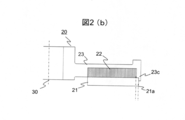
- FIG. 2 (b) is an enlarged cross-sectional view of the rotor in the present embodiment
- FIG. 2 (c) is an enlarged cross-sectional view of the projection of the support member in the present embodiment.
- the thickness of the support member 23 based on the end face of the yoke 22 not facing the permanent magnet 21 corresponds to the first portion 23d facing the first region 20b and the yoke 22.
- the thickness T1 of the supporting member 23 in the first portion 23d> the thickness Ty of the supporting member 23 in the yoke opposing portion 23e is obtained.
- the axial type motor of the present embodiment since the support member 23 of the first portion 23d is thickened, when the support member 23 is formed of a soft magnetic material, the magnetic resistance of the magnetic circuit can be reduced. .
- the support member 23 is formed of a nonmagnetic material, the magnetic flux emitted from a certain magnetic pole of the permanent magnet 21 passes through the yoke 22 of the soft magnetic material and enters the adjacent magnetic pole.
- the support member 23 when the support member 23 is made of a soft magnetic material, the support member 23 also forms a magnetic circuit, especially around the first region 20b.
- the magnetic flux density of the yoke 22 is increased and the magnetic resistance of the yoke 22 is increased, so that it becomes easy to pass through the first region 20b.
- iron having the support member 23 has a low permeability and tends to be magnetically saturated, as compared with the electromagnetic steel sheet generally forming the yoke 22. Therefore, by thickening the support member 23 in the first portion 23d as in the present embodiment, the amount of leakage flux to the outside of the magnetic circuit is reduced, and the output torque and the efficiency of the motor are improved.
- balance correction of the rotor 20 can also be performed using this thickened portion.
- the diameter of the rotor 20 is larger than that of the radial type, so the inertia tends to be large.
- Balance correction is important to reduce the load on the bearing and reduce bearing life and mechanical loss. Although it is effective to provide the balance correction allowance on the outer diameter side, there is a possibility that the diameter of the rotor 20 may be enlarged.
- the rotor structure of this embodiment allows balance correction without increasing the diameter of the rotor 20.
- the present effect is also effective when the support member 23 is made of a soft magnetic material.
- FIGS. 3A to 3C are diagrams for explaining an example in which the present invention is applied to a double rotor axial type motor. Descriptions of structures, operations, and effects overlapping with FIGS. 1A to 1E and FIGS. 2A to 2C will be omitted.
- FIG. 3A is a cross-sectional perspective view of the axial type rotating electric machine in the present embodiment.
- the enlarged sectional view of the rotor in a present Example is shown in FIG.3 (b).
- the figure which looked at the permanent magnet and yoke from the axial direction of the rotating shaft in FIG.3 (c) is shown.
- the inner diameter of the permanent magnet 21 is smaller than the inner diameter of the yoke 22, and the second region 20 c does not overlap the yoke 22.
- the second region 20c in which the projection 21b of the permanent magnet 21 and the projection 22b of the yoke 22 do not overlap is formed in the permanent magnet 21.
- the second region 20 c is formed on the inner diameter side of the permanent magnet 21 and on the inner diameter side of the first region 20 b.
- the thickness of the support member 23 based on the end face of the yoke 22 not facing the permanent magnet 21 was compared between the second portion 23 f facing the second region 20 c and the yoke facing portion 23 e facing the yoke 22.
- the thickness T2 of the support member 23 in the second portion 23f> the thickness Ty of the support member 23 in the yoke facing portion 23e is satisfied.
- the permanent magnet 21 faces the support member 23 via the first area 20b and the second area 20c. Since the first area 20b and the second area 20c of the support member 23 are formed with high dimensional accuracy as compared with the yoke end face formed of laminated electromagnetic steel plates or the like, the angle of the permanent magnet 21 with respect to the rotation axis is managed. easy. Further, in the case of bonding the permanent magnet 21, a reliable bonding surface can be secured. Furthermore, since the second portion 23f is thickened, the magnetic resistance can be reduced as in the second embodiment, and the torque and the efficiency can be improved.
- FIGS. 4 (a) to 4 (f) are diagrams for explaining an example in which the present invention is applied to a double rotor axial motor having one stator and two rotors.
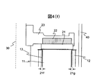
- FIG. 4 (a) is a cross-sectional perspective view of the motor (axial type rotating electrical machine) in the present embodiment
- FIG. 4 (b) is a perspective view of the motor in the present embodiment.
- the axial type electric rotating machine 100 of FIG. 4A includes a stator 20 and a rotor 20 disposed via an air gap so as to sandwich the stator 10 from the direction of the rotation shaft 30 passing through the stator 10, and fixed It comprises a housing 40 for holding the element 10 and a shaft 50 for holding the rotor 20 through a bearing (not shown).
- the rotor 20 faces the stator 10 along the axial direction of the rotation shaft 30.
- the housing 40 and the shaft 50 are not shown in FIG. Also, the air gap is shown enlarged so that the structure of the stator 10 can be understood.
- the stator 10 electrically insulates the stator core 11 using a plurality of soft magnetic members arranged in the circumferential direction, the winding 12 wound around the stator core 11, the stator core 11 and the winding 12
- the bobbin 13 to be The stator core 11, the winding 12, and the bobbin 13 are molded integrally with the housing 40 with resin.
- the rotor 20 has a permanent magnet 21 disposed opposite to the axial end face of the stator core 11, a yoke 22 of a soft magnetic material disposed on the back of the permanent magnet 21, a permanent magnet 21 and a yoke 22 as a shaft 50. And a support member 23 for holding and supporting the yoke 22.
- the yoke 22 is disposed to face the stator core 11 with the permanent magnet 21 interposed therebetween.
- the support member 23 is fixed to the rotating shaft
- FIG. 4C is a cross-sectional view of an axial type rotary electric machine in the present embodiment.
- the enlarged sectional view of the rotor in a present Example is shown in FIG.4 (d).
- the support member 23 has a protrusion 23 c that protrudes so as to face the side surface 21 a of the permanent magnet 21 on the side far from the rotation shaft 30.
- the figure which looked at the permanent magnet and yoke from the axial direction of the rotating shaft is shown in FIG.4 (e).
- the outer diameter of the permanent magnet 21 is larger than the outer diameter of the yoke, and has a first region 20 b which does not overlap with the yoke 22. Further, the inner diameter of the permanent magnet 21 is smaller than the inner diameter of the yoke 22, and the second region 20 c does not overlap the yoke 22.
- the thickness of the support member 23 based on the end face of the yoke 22 not facing the permanent magnet 21 was compared between the first portion 23 d facing the first region 20 b and the yoke facing portion 23 e facing the yoke 22.
- the second portion 23f facing the second region 20c and the yoke facing portion 23e facing the yoke 22
- the thickness T2 of the support member 23 in the second portion 23f> the thickness Ty of the support member 23 in the yoke facing portion 23e is satisfied.
- FIG. 4F is an enlarged view around the permanent magnet and the stator core in the present embodiment.
- FIG. 4F shows the difference 21f between the inner diameter of the permanent magnet 21 and the inner diameter of the stator core 11, and the difference 21g between the outer diameter of the permanent magnet 21 and the outer diameter of the stator core 11.
- the inner diameter of the permanent magnet 21 ⁇ the inner diameter of the stator core 11 the outer diameter of the permanent magnet 21> the stator core It is 11 "outside diameter.
- the operation of the axial motor of this embodiment will be described.
- An alternating current is supplied to the winding using an inverter or an alternating current power supply (not shown).
- an alternating magnetic field is formed on the stator surface.
- the alternating magnetic field and the DC magnetic field of the permanent magnet attract and repel each other to rotate the rotor and generate torque. Also, due to the rotation, centrifugal force acts on the rotor radially outward.
- the permanent magnet 21 and the yoke 22 can be held from the outer peripheral side by the projection 23 c of the support member 23, so that scattering of the permanent magnet 21 and the yoke 22 can be suppressed.
- the first region 20b it is possible to reduce the radial thickness of the protrusion 23c that holds the permanent magnet 21 while maintaining the strength of the protrusion 23c against the centrifugal force. Thereby, expansion of the diameter of the rotor 20 by the projection part 23c can be minimized. Since the ratio of the diameter of the permanent magnet 21 to the diameter of the rotor 20 can be increased, high torque and high efficiency of the motor can be achieved. Since the diameter of the rotor 20 can be reduced, the diameter of the housing 40 can be reduced, and a winding crossover wire can be arranged between the outer peripheral surface of the rotor 20 and the housing 40.
- the support member 23 may be a soft magnetic material or a nonmagnetic material.
- the permanent magnet 21 can be opposed to the support member 23 via the first region 20b and the second region 20c. Since the first area 20b and the second area 20c of the support member 23 are formed with high dimensional accuracy as compared with the yoke end face formed of laminated electromagnetic steel sheets or the like, the angle of the permanent magnet 21 with respect to the rotation shaft 30 is managed Easy to do. Further, in the case of bonding the permanent magnet 21, a reliable bonding surface can be secured.
- the support member 23 of the first portion 23d and the second portion 23f is thickened, when the support member 23 is made of a soft magnetic material, the magnetic resistance of the magnetic circuit can be reduced.
- the support member 23 is formed of a nonmagnetic material, the magnetic flux emitted from a certain magnetic pole of the permanent magnet 21 passes through the yoke 22 of the soft magnetic material and enters the adjacent magnetic pole.
- the support member 23 is made of a soft magnetic material, the support member 23 also forms a magnetic circuit centering on the first region 20b and the second region 20c.
- the magnetic flux density of the yoke 22 is increased and the magnetic resistance of the yoke 22 is increased, so that it is easy to pass the first region 20b and the second region 20c .
- iron having the support member 23 has a low permeability and tends to be magnetically saturated, as compared with the electromagnetic steel sheet generally forming the yoke 22. Therefore, by thickening the first portion 23d and the second portion 23f as in this embodiment, the amount of leakage flux to the outside of the magnetic circuit is reduced, and the output torque and the efficiency of the motor are improved.
- the magnetic flux of the permanent magnet 21 is overhanged by overhanging the permanent magnet 21 as “the inner diameter of the permanent magnet 21 ⁇ the inner diameter of the stator core 11” and “the outer diameter of the permanent magnet 21> the outer diameter of the stator core 11”. The amount can be increased to improve the torque and efficiency of the motor.
- a combination of preferable materials in the motor of the present invention there is a combination using a ferrite magnet as a permanent magnet material and an amorphous metal as a stator core.
- Ferrite magnets are inferior in magnetic force to neodymium magnets and samarium cobalt magnets. In order to compensate for this, it is desirable to enlarge the surface area of the magnet and use it thick.
- the amorphous metal is a soft magnetic material having a high permeability and a small loss. Low saturation magnetic flux density is a weak point for use in combination with neodymium magnets, but is sufficient for ferrite magnets. The magnetic flux can be more effectively utilized by using the ferrite magnet as an overhang.
- this embodiment shows an example applied to a double rotor type axial motor, it may be a single rotor type axial motor in which a pair of stators and a rotor face each other. Moreover, not a motor but a generator may be used.
- the magnet may be divided
- FIG. 5 is a view for explaining an example in which the present invention is applied to an axial type motor. 1 (a) to 1 (e), 2 (a) to 2 (c), 3 (a) to 3 (c), 4 (a) to 4 (f). Descriptions of structure, operation and effects are omitted.
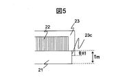
- FIG. 5 is an enlarged view of the vicinity of the projection of the support member in the motor of this embodiment.
- the height H1 of the protrusion 23c facing the outer peripheral surface of the permanent magnet 21 is 50% or less of the thickness Tm of the permanent magnet 21, and further about 20% (15% to 25%, preferably 18% to 22%) Is desirable.
- a reaction force from the protrusion 23 c acts on the outer peripheral surface of the permanent magnet 21.
- H1 the surface pressure applied to the permanent magnet 21 can be reduced, and damage due to centrifugal force can be suppressed.
- H1 is made smaller, it is possible to suppress the leakage flux to the protrusion 23c.
- About 20% is the result of setting it as the largest H1 that can sufficiently suppress the leakage flux.
Abstract
回転子の大きさに対するトルクや効率を向上させるアキシャル型回転電機を提供する。固定子コアを有する固定子と、固定子を通る回転軸の軸方向に沿って固定子と対向する回転子と、を備え、回転子は、回転軸の軸方向に固定子コアと対向して配置される永久磁石と、永久磁石を挟んで固定子コアと対向して配置されるヨークと、ヨークを支持する支持部材と、を有し、支持部材は、回転軸から遠い側の永久磁石の側面と対向するように突出する突起部を有し、回転軸の軸方向に沿って射影した場合、永久磁石に永久磁石の投影部がヨークの投影部と重ならない第1領域が形成され、第1領域は、永久磁石の外径側に形成され、第1領域が突起部の側部に形成されるアキシャル型回転電機。
Description
本発明は、回転子の大きさに対するトルクや効率を向上させることができる回転子および回転子を用いたアキシャル型回転電機に関する。
近年、アキシャル型の回転電機が注目されている。本回転電機は、円盤状の回転子と固定子が対向して配置された構造を有し、回転電機の薄型、扁平化に有利な構成である。また、本回転電機においては、固定子を軸方向から2枚の回転子で挟み込んだダブルロータ型で構成することも可能である。一般的なダブルロータ型の回転電機は、独立したコアに巻線を巻回したものを周方向に複数個配置し、樹脂でモールドした固定子と、周方向に複数配置した永久磁石をヨークに接続した回転子から構成されている。モータのトルクは、回転子と固定子の対向面であるギャップ面積に比例するが、ダブルロータ型は、体格あたりのギャップ面積を大きくできるので回転電機の高出力化、高効率化に有効である。さらに、著者らは、低損失を特徴としたアモルファス金属の適用にも有効な構造と考えている。アモルファス金属は、硬く脆いため加工が難しい。ダブルロータ型の回転電機は、固定子コアをオープンスロットとすることで、略直方体という非常に単純な形状でコアを構成できる。このため、アモルファス金属を簡単な方法でコア形状に加工することが可能である。
アキシャル型回転電機において、トルクや効率を向上するためには、径を拡大し、固定子と回転子が対向する面積(以下、ギャップ面積)を増加することが有効である。ただし、これにより回転子に働く遠心力が増加するため注意が必要である。特に、アキシャル型の回転電機では、永久磁石を回転子表面に設置した表面磁石型の構成を取る場合が多く、遠心力による磁石の飛散、破損が課題となる。
アキシャル型回転電機の回転子構造については、先行技術の一例を以下に示す。
特許文献1、特許文献2記載の回転子は、永久磁石とヨーク、および、これらを保持しシャフトに固定する支持部材とから構成されている。支持部材の外径側には、永久磁石の外周面を覆う突起部を設け、遠心力に対する強度を向上している。このような回転子構造は、アキシャル型回転電機に関する他の発明でも共通に見られるものである。
特許文献1、特許文献2に代表して説明した一般的なアキシャル型回転電機の回転子構造では、遠心力に対する強度を向上しようとすると、支持部材の突起部を径方向に厚肉化する必要があり、回転子の外径が拡大してしまう。一般に、アキシャル型回転電機の回転子外周には、ハウジングや固定子巻線の渡り線などが配置されている。回転子の外径はこれらの部材の寸法により制約されるため、突起部の径方向厚みが増加すると、永久磁石の外径を縮小することになる。これにより、回転電機のトルクや効率の低下を招く。
そこで、本発明では、回転子の大きさに対するトルクや効率を向上させることができる回転子および回転子を用いたアキシャル型回転電機を提供する。
上記目的を達成するために、本発明の特徴は例えば、以下の通りである。
固定子コアを有する固定子と、固定子を通る回転軸の軸方向に沿って固定子と対向する回転子と、を備え、回転子は、回転軸の軸方向に固定子コアと対向して配置される永久磁石と、永久磁石を挟んで固定子コアと対向して配置されるヨークと、ヨークを支持する支持部材と、を有し、支持部材は、回転軸から遠い側の永久磁石の側面と対向するように突出する突起部を有し、回転軸の軸方向に沿って射影した場合、永久磁石に永久磁石の投影部がヨークの投影部と重ならない第1領域が形成され、第1領域は、永久磁石の外径側に形成され、第1領域が突起部の側部に形成されるアキシャル型回転電機。
本発明の回転子および回転子を用いたアキシャル型回転電機は、回転子の大きさに対するトルクや効率を向上させることができる。上記した以外の課題、構成及び効果は以下の実施形態の説明により明らかにされる。
以下、本発明の実施例について図面を参照して説明する。本明細書に開示される技術的思想の範囲内において当業者による様々な変更および修正が可能である。また、本発明を説明するための全図において、同一の機能を有するものは、同一の符号を付け、その繰り返しの説明は省略する場合がある。
図6(a)は、従来のアキシャル型回転電機の断面斜視図であり、図6(b)は、従来の回転子の拡大断面図である。図6(a)、図6(b)における符号の説明は、以下の実施例に記載されている。
図6(b)において、永久磁石21を回転軸30の軸方向に沿って射影した場合、永久磁石21に、永久磁石21の投影部21bとヨーク22の投影部22bとが一致しているため、永久磁石21を保持する突起部23cの径方向における厚みを小さくすることが難しい。
図1(a)から図1(e)は、本発明を1つの固定子と2つの回転子とを備えたダブルロータ型のアキシャル型モータに適用した一例を説明するための図である。図1(a)には、本実施例におけるモータ(アキシャル型回転電機100)の断面斜視図を、図1(b)には、本実施例におけるアキシャル型回転電機の斜視図を示す。
図1(a)のアキシャル型回転電機100は、固定子10と固定子10を通る回転軸30の方向から固定子10を挟み込むように、エアギャップを介して配置された回転子20、および、固定子10を保持するハウジング40、回転子20を図示しない軸受を介して保持するシャフト50とからなる。回転子20は、回転軸30の軸方向に沿って固定子10と対向している。
図1(b)では、ハウジング40とシャフト50の図示を省略している。また、固定子10の構造がわかるようエアギャップを拡大して示している。固定子10は、周方向に複数配置された軟磁性体の固定子コア11、固定子コア11に巻回された巻線12、固定子コア11と巻線12とを電気的に絶縁するボビン13、を有する。固定子コア11、巻線12、ボビン13は、樹脂でハウジング40と一体にモールドされている。回転子20は、固定子コア11の軸方向端面に対向して配置される永久磁石21、永久磁石21の背面に配置された軟磁性体のヨーク22、永久磁石21とヨーク22をシャフト50に保持し、ヨーク22を支持する支持部材23とからなる。ヨーク22は、永久磁石21を挟んで固定子コア11と対向して配置されている。支持部材23は、回転軸30に固定されている。
図1(c)に本実施例における回転子の拡大断面図、図1(d)に本実施例における支持部材の突起部の拡大断面図を示す。支持部材23は、回転軸30から遠い側の永久磁石21の側面21aに対向するように突出する突起部23cを有している。
図1(e)に、永久磁石とヨークを回転軸の軸方向から見た図を示す。永久磁石21の外径は、ヨーク22の外径より大きくなっており、ヨーク22と重ならない第1領域20bを有している。換言すると、永久磁石21を回転軸30の軸方向に沿って射影した場合、永久磁石21に、永久磁石21の投影部21bとヨーク22の投影部22bとが重ならない第1領域20bが形成されている。第1領域20bは、永久磁石21の外径側に形成されている。第1領域20bが突起部23cの側部に形成されるように、永久磁石21が配置されている。
本実施例のアキシャル型モータの動作を説明する。ここでは、モータの動作例について説明する。インバータや交流電源(図示なし)を用い巻線に交流電流を通電する。これにより、固定子表面に交番磁界が形成される。この交番磁界と永久磁石の直流磁界が吸引、反発することで、回転子が回転しトルクを発生する。また、回転により、回転子には、径方向外側に遠心力がはたらく。
本実施例のアキシャル型モータの効果を説明する。本発明のアキシャル型回転電機100では、支持部材23の突起部23cにより、永久磁石21およびヨーク22を外周側から保持することができるため、永久磁石21やヨーク22が飛散することを抑制できる。また、第1領域20bを形成することで、遠心力に対する突起部23cの強度を維持しつつ、永久磁石21を保持する突起部23cの径方向厚みを縮小することができる。これにより、突起部23cによる回転子径の拡大を最小限に抑えることができる。回転子20の径に対する永久磁石21の径の比率を大きくすることができるため、モータの高トルク化、高効率化を図ることができる。また、突起部23cの径方向厚みが大きくなるため、支持部材23を鋳造製作する場合の、材料の流れが良く製造性にも優れる。支持部材23は、軟磁性体であっても非磁性体であってもよい。回転子20の径を小さくすることができるため、ハウジング40の径の縮小、および、回転子20の外周面とハウジング40との間に巻線の渡り線を配置するなども可能になる。
本実施例では、ダブルロータ型のアキシャル型モータに適用した例を示したが、一対の固定子と回転子とが対向したシングルロータ型のアキシャル型モータであってもよい。また、モータではなく発電機であってもよい。また、本実施例では、リング状の永久磁石形状について記載したが、磁石は分割されていても良い。また、永久磁石21とヨーク22で接する部分の両者の径を同じにして、永久磁石21にテーパをつけることで第1領域20bが形成されるようにしてもよい。
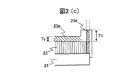
図2(a)から図2(c)は、本発明をダブルロータ型のアキシャル型モータに適用した一例を説明するための図である。図1(a)から図1(e)と重複する構造、動作、効果の説明は割愛する。図2(a)は、本実施例におけるアキシャル型回転電機の断面斜視図である。
図2(b)に、本実施例における回転子の拡大断面図、図2(c)に、本実施例における支持部材の突起部の拡大断面図を示す。図2(c)において、回転子20は、永久磁石21と対向しない側のヨーク22の端面を基準とした支持部材23の厚みが、第1領域20bに対向した第1部分23dとヨーク22に対向するヨーク対向部23eとで比較した場合、「第1部分23dにおける支持部材23の厚みT1>ヨーク対向部23eにおける支持部材23の厚みTy」となっている。
本実施例のアキシャル型モータの効果を説明する。本実施例のアキシャル型モータでは、第1部分23dの支持部材23が厚肉化されるため、支持部材23を軟磁性材で構成した場合には、磁気回路の磁気抵抗を低減することができる。支持部材23を非磁性体で構成した場合、永久磁石21のある磁極から出た磁束は、軟磁磁性体のヨーク22を通り、隣接する磁極に入る。一方、支持部材23を軟磁性体で構成すると、特に第1領域20bを中心として支持部材23も磁気回路を形成する。特に、回転子20の薄型化を図るためヨーク22の薄肉化を図ると、ヨーク22の磁束密度が高まり、ヨーク22の磁気抵抗が増加するため、第1領域20bを通り易くなる。このとき、一般にヨーク22を形成する電磁鋼板に比較し、支持部材23を形成する鉄は、透磁率が低く磁気飽和し易い。そこで、本実施例のように第1部分23dにおける支持部材23を厚肉化することで、磁気回路外への漏れ磁束量を低減し、モータの出力トルクや効率が向上する。
さらに、この厚肉化部分を利用して回転子20のバランス修正を行うこともできる。アキシャル型モータでは、回転子20の径がラジアル型と比較し大径化するため、イナーシャが大きくなる傾向にある。軸受への負荷を低減し、軸受寿命や機械損を低減するためにバランス修正が重要である。バランス修正代は、外径側に設けるのが有効であるが、一方で、回転子20の径を拡大してしまう可能性がある。本実施例の回転子構造は、回転子20の径を拡大することなく、バランス修正が可能である。本効果は、支持部材23を軟磁性体で構成したときにも有効である。
図3(a)から図3(c)は、本発明をダブルロータ型のアキシャル型モータに適用した一例を説明するための図である。図1(a)から図1(e)、図2(a)から図2(c)と重複する構造、動作、効果の説明は割愛する。
図3(a)は、本実施例におけるアキシャル型回転電機の断面斜視図である。図3(b)に、本実施例における回転子の拡大断面図を示す。図3(c)に、永久磁石とヨークを回転軸の軸方向から見た図を示す。
本実施例の回転子10において、永久磁石21の内径は、ヨーク22の内径より小さくなっており、ヨーク22と重ならない第2領域20cを有している。換言すると、永久磁石21を回転軸30の軸方向に沿って射影した場合、永久磁石21に、永久磁石21の投影部21bとヨーク22の投影部22bとが重ならない第2領域20cが形成されている。第2領域20cは、永久磁石21の内径側、第1領域20bよりも内径側に形成されている。また、永久磁石21と対向しない側のヨーク22の端面を基準とした支持部材23の厚みが、第2領域20cに対向した第2部分23fとヨーク22に対向するヨーク対向部23eとで比較した場合、「第2部分23fにおける支持部材23の厚みT2>ヨーク対向部23eにおける支持部材23の厚みTy」となっている。
本実施例のアキシャル型モータの効果を説明する。本実施例のアキシャル型モータでは、永久磁石21が第1領域20bと第2領域20cとを介し支持部材23に対向する。支持部材23の第1領域20b、第2領域20cは、積層の電磁鋼板などで構成されたヨーク端面に比較し、高い寸法精度で形成されるため、永久磁石21の回転軸に対する角度を管理し易い。また、永久磁石21を接着する場合には、確実な接着面を確保することができる。さらに、第2部分23fが厚肉化されているため、実施例2と同様に磁気抵抗を低減することができ、トルク、効率を向上することができる。
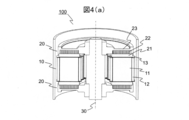
図4(a)から図4(f)は、本発明を1つの固定子と2つの回転子とを備えたダブルロータ型のアキシャル型モータに適用した一例を説明するための図である。
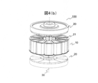
図4(a)には、本実施例におけるモータ(アキシャル型回転電機)の断面斜視図を、図4(b)には、本実施例におけるモータの斜視図を示す。
図4(a)のアキシャル型回転電機100は、固定子10と固定子10を通る回転軸30の方向から固定子10を挟み込むようにエアギャップを介して配置された回転子20、および、固定子10を保持するハウジング40、回転子20を図示しない軸受を介して保持するシャフト50とからなる。回転子20は、回転軸30の軸方向に沿って固定子10と対向している。
図4(b)では、ハウジング40とシャフト50の図示を省略している。また、固定子10の構造がわかるようエアギャップを拡大して示している。固定子10は、周方向に複数配置された軟磁性体を用いた固定子コア11、固定子コア11に巻回された巻線12、固定子コア11と巻線12とを電気的に絶縁するボビン13、を有する。固定子コア11、巻線12、ボビン13は、樹脂でハウジング40と一体にモールドされている。回転子20は、固定子コア11の軸方向端面に対向して配置される永久磁石21、永久磁石21の背面に配置された軟磁性体のヨーク22、永久磁石21とヨーク22をシャフト50に保持し、ヨーク22を支持する支持部材23とからなる。ヨーク22は、永久磁石21を挟んで固定子コア11と対向して配置されている。支持部材23は、回転軸30に固定されている。
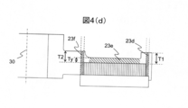
図4(c)に、本実施例におけるアキシャル型回転電機断面図を示す。図4(d)に、本実施例における回転子の拡大断面図を示す。支持部材23は、回転軸30から遠い側の永久磁石21の側面21aに対向するように突出する突起部23cを有している。
図4(e)に、永久磁石とヨークを回転軸の軸方向から見た図を示す。永久磁石21の外径は、ヨークの外径より大きくなっており、ヨーク22と重ならない第1領域20bを有している。また、永久磁石21の内径は、ヨーク22の内径より小さくなっており、ヨーク22と重ならない第2領域20cを有している。
さらに、永久磁石21と対向しない側のヨーク22の端面を基準とした支持部材23の厚みが、第1領域20bに対向した第1部分23dとヨーク22に対向するヨーク対向部23eとで比較した場合、「第1部分23dにおける支持部材23の厚みT1>ヨーク対向部23eにおける支持部材23の厚みTy」、第2領域20cに対向した第2部分23fとヨーク22に対向するヨーク対向部23eとで比較した場合、「第2部分23fにおける支持部材23の厚みT2>ヨーク対向部23eにおける支持部材23の厚みTy」となっている。
図4(f)は、本実施例における永久磁石、固定子コア周辺の拡大図である。図4(f)には、永久磁石21の内径と固定子コア11の内径の差異21fおよび永久磁石21の外径と固定子コア11の外径の差異21gが示されている。図4(f)において、永久磁石21の径と固定子コア11の径を比較した場合、「永久磁石21の内径<固定子コア11の内径」、「永久磁石21の外径>固定子コア11の外径」となっている。
本実施例のアキシャル型モータの動作を説明する。ここでは、モータの動作例について説明する。インバータや交流電源(図示なし)を用い巻線に交流電流を通電する。これにより、固定子表面に交番磁界が形成される。この交番磁界と永久磁石の直流磁界が吸引、反発することで、回転子が回転しトルクを発生する。また、回転により、回転子には、径方向外側に遠心力がはたらく。
本実施例のアキシャル型モータの効果を説明する。本実施例のアキシャル型モータでは、支持部材23の突起部23cにより、永久磁石21およびヨーク22を外周側から保持することができるため、永久磁石21やヨーク22が飛散することを抑制できる。
また、第1領域20bを形成することで、遠心力に対する突起部23cの強度を維持しつつ、永久磁石21を保持する突起部23cの径方向厚みを縮小することができる。これにより、突起部23cによる回転子20の径の拡大を最小限に抑えることができる。回転子20の径に対する永久磁石21の径の比率を大きくすることができるため、モータの高トルク化、高効率化を図ることができる。回転子20の径を小さくすることができるため、ハウジング40の径の縮小、および、回転子20の外周面とハウジング40との間に巻線の渡り線を配置するなども可能になる。
また、突起部23cの径方向厚みが厚くなるため、支持部材23を鋳造製作する場合の、材料の流れが良く製造性にも優れる。支持部材23は、軟磁性体であっても非磁性体であってもよい。
第2領域20cを形成することで、永久磁石21を第1領域20bと第2領域20cとを介し支持部材23に対向させることができる。支持部材23の第1領域20b、第2領域20cは、積層の電磁鋼板などで構成されたヨーク端面に比較し、高い寸法精度で形成されるため、永久磁石21の回転軸30に対する角度を管理し易い。また、永久磁石21を接着する場合には、確実な接着面を確保することができる。
また、第1部分23d、第2部分23fの支持部材23が厚肉化されるため、支持部材23を軟磁性材で構成した場合には、磁気回路の磁気抵抗を低減することができる。支持部材23を非磁性体で構成した場合、永久磁石21のある磁極から出た磁束は、軟磁磁性体のヨーク22を通り、隣接する磁極に入る。一方、支持部材23を軟磁性体で構成すると、特に第1領域20b、第2領域20cを中心として支持部材23も磁気回路を形成する。特に回転子20の薄型化を図るため、ヨーク22の薄肉化を図るとヨーク22の磁束密度が高まり、ヨーク22の磁気抵抗が増加するため、第1領域20b、第2領域20cを通り易くなる。このとき、一般にヨーク22を形成する電磁鋼板に比較し、支持部材23を形成する鉄は、透磁率が低く磁気飽和し易い。そこで、本実施例のように第1部分23dおよび第2部分23fを厚肉化することで、磁気回路外への漏れ磁束量を低減し、モータの出力トルクや効率が向上する。
さらに、「永久磁石21の内径<固定子コア11の内径」、「永久磁石21の外径>固定子コア11の外径」として、永久磁石21をオーバーハングさせることで、永久磁石21の磁束量を増加させ、モータのトルク、効率を向上させることができる。
本発明のモータにおける、好適な材料の組合せとして、永久磁石材にフェライト磁石、固定子コアにアモルファス金属を用いた組合せがある。フェライト磁石は、ネオジム磁石やサマリウムコバルト磁石などに比較し磁力が劣る。これを補うため磁石の表面積を拡大し、厚みを厚くして利用することが望まれる。本実施例を適用することで、回転子径の拡大をおさえつつ、フェライト磁石の大径化を図ることができる。また、アモルファス金属は、透磁率が高く損失の小さい軟磁性材である。ネオジム磁石と組合せて用いるには、飽和磁束密度が低いことが弱点となるが、フェライト磁石に対しては十分である。フェライト磁石をオーバーハングさせて用いることで、より磁石磁束を有効に活用することができる。
本実施例では、ダブルロータ型のアキシャル型モータに適用した例を示したが、一対の固定子と回転子とが対向したシングルロータ型のアキシャル型モータであってもよい。また、モータではなく発電機であってもよい。
また、本実施例では、リング状の永久磁石形状について記載したが、磁石は分割されていても良い。
図5は、本発明をアキシャル型モータに適用した一例を説明するための図である。図1(a)から図1(e)、図2(a)から図2(c)、図3(a)から図3(c)、図4(a)から図4(f)と重複する構造、動作、効果の説明は割愛する。
図5は、本実施例のモータにおける支持部材の突起部周辺の拡大図である。永久磁石21の外周面と対向する突起部23cの高さH1は、永久磁石21の厚みTmの50%以下、さらに、約20%(15%以上25%以下、好ましくは18%以上22%以下)とすることが望ましい。永久磁石21の外周面には、突起部23cからの反力が働く。H1を大きくした方が永久磁石21にかかる面圧を小さくすることができ、遠心力による破損を抑制できる。一方、H1を小さくした方が、突起部23cへの漏れ磁束を抑制できる。約20%は、漏れ磁束を十分抑制できる最大のH1とした結果である。
本実施例のアキシャル型モータの効果を説明する。突起部23cの高さを上記寸法とすることで、永久磁石21から突起部23cへの漏れ磁束量を低減し、モータのトルク、効
率を向上することができる。
率を向上することができる。
10…固定子
11…固定子コア
12…巻線
20…回転子
20b…第1領域
20c…第2領域
21…永久磁石
21a…永久磁石の側面
21b…永久磁石の投影部
22…ヨーク
22b…ヨークの投影部
23…支持部材
23c…突起部
23d…第1部分
23e…ヨーク対向部
23f…第2部分
30…回転軸
40…ハウジング
50…シャフト
100…アキシャル型回転電機
11…固定子コア
12…巻線
20…回転子
20b…第1領域
20c…第2領域
21…永久磁石
21a…永久磁石の側面
21b…永久磁石の投影部
22…ヨーク
22b…ヨークの投影部
23…支持部材
23c…突起部
23d…第1部分
23e…ヨーク対向部
23f…第2部分
30…回転軸
40…ハウジング
50…シャフト
100…アキシャル型回転電機
Claims (8)
- 固定子コアを有する固定子と、
前記固定子を通る回転軸の軸方向に沿って前記固定子と対向する回転子と、を備え、
前記回転子は、
前記回転軸の軸方向に前記固定子コアと対向して配置される永久磁石と、
前記永久磁石を挟んで前記固定子コアと対向して配置されるヨークと、
前記ヨークを支持する支持部材と、を有し、
前記支持部材は、前記回転軸から遠い側の前記永久磁石の側面と対向するように突出する突起部を有し、
前記回転軸の軸方向に沿って射影した場合、前記永久磁石に前記永久磁石の投影部が前記ヨークの投影部と重ならない第1領域が形成され、
前記第1領域は、前記永久磁石の外径側に形成され、
前記第1領域が前記突起部の側部に形成されるアキシャル型回転電機。 - 請求項1において、
前記支持部材は、前記第1領域と対向する第1部分および前記ヨーク部と対向するヨーク対向部を有し、
前記第1部分における前記支持部材の厚みは、前記ヨーク対向部における前記支持部材の厚みよりも大きいアキシャル型回転電機。 - 請求項1または2において、
前記回転軸の軸方向に沿って射影した場合、前記永久磁石に前記永久磁石の投影部が前記ヨークの投影部と重ならない第2領域が形成され、
前記第2領域は、前記永久磁石の内径側に形成されるアキシャルギャップ型回転電機。 - 請求項3において、
前記支持部材は、前記第2領域と対向する第2部分を有し、
前記第2部分における前記支持部材の厚みは、前記ヨーク対向部における前記支持部材の厚みよりも大きいアキシャルギャップ型回転電機。 - 請求項1乃至4のいずれかにおいて、
前記永久磁石の内径は前記固定子コアの内径よりも小さく、
前記永久磁石の外径は前記固定子コアの外径よりも大きいアキシャル型回転電機。 - 請求項1乃至5のいずれかにおいて、
前記永久磁石の外周面と対向する前記突起部の高さが、前記永久磁石の厚みに対し、50%以下であるアキシャル型回転電機。 - 請求項1乃至6のいずれかにおいて、
前記永久磁石の外周面と対向する前記突起部の高さが、前記永久磁石の厚みに対し、15%以上25%以下であるアキシャル型回転電機。 - 請求項1乃至6のいずれかにおいて、
前記永久磁石にフェライトが用いられ、
前記固定子コアにアモルファス金属が用いられるアキシャル型回転電機。
Priority Applications (3)
| Application Number | Priority Date | Filing Date | Title |
|---|---|---|---|
| CN201480013612.2A CN105052015B (zh) | 2013-06-28 | 2014-01-22 | 轴向型旋转电机 |
| US14/780,658 US9935510B2 (en) | 2013-06-28 | 2014-01-22 | Axial-type rotary electric machine |
| EP14817066.5A EP3016249B1 (en) | 2013-06-28 | 2014-01-22 | Axial type rotating electrical machine |
Applications Claiming Priority (2)
| Application Number | Priority Date | Filing Date | Title |
|---|---|---|---|
| JP2013-135747 | 2013-06-28 | ||
| JP2013135747A JP6055725B2 (ja) | 2013-06-28 | 2013-06-28 | 回転子および回転子を用いたアキシャル型回転電機 |
Publications (1)
| Publication Number | Publication Date |
|---|---|
| WO2014208110A1 true WO2014208110A1 (ja) | 2014-12-31 |
Family
ID=52141469
Family Applications (1)
| Application Number | Title | Priority Date | Filing Date |
|---|---|---|---|
| PCT/JP2014/051193 WO2014208110A1 (ja) | 2013-06-28 | 2014-01-22 | アキシャル型回転電機 |
Country Status (5)
| Country | Link |
|---|---|
| US (1) | US9935510B2 (ja) |
| EP (1) | EP3016249B1 (ja) |
| JP (1) | JP6055725B2 (ja) |
| CN (1) | CN105052015B (ja) |
| WO (1) | WO2014208110A1 (ja) |
Families Citing this family (12)
| Publication number | Priority date | Publication date | Assignee | Title |
|---|---|---|---|---|
| US10797573B2 (en) * | 2014-04-16 | 2020-10-06 | Power It Perfect, Inc. | Axial motor/generator having multiple inline stators and rotors with stacked/layered permanent magnets, coils, and a controller |
| CN107408859B (zh) * | 2015-03-04 | 2019-07-26 | 株式会社日立产机系统 | 轴向间隙型旋转电机和定子 |
| JP6771537B2 (ja) * | 2016-02-24 | 2020-10-21 | 株式会社日立製作所 | アキシャルギャップ型回転電機 |
| USD841703S1 (en) * | 2016-05-19 | 2019-02-26 | Sumitomo Electric Sintered Alloy, Ltd. | Core for rotary electric machine |
| CN109643922A (zh) * | 2017-01-31 | 2019-04-16 | 株式会社日立产机系统 | 轴向间隙型旋转电机 |
| US11757327B2 (en) | 2018-01-31 | 2023-09-12 | Minebea Mitsumi Inc. | Rotor, motor, and method for manufacturing rotor |
| JP6935342B2 (ja) * | 2018-01-31 | 2021-09-15 | ミネベアミツミ株式会社 | ロータ、モータおよびロータの製造方法 |
| JP2019161723A (ja) * | 2018-03-08 | 2019-09-19 | 株式会社日立産機システム | アキシャルギャップ型回転電機 |
| EP3846318A4 (en) * | 2018-08-31 | 2022-06-08 | Zhejiang Pangood Power Technology Co., Ltd. | SEGMENT CORE AND AXIAL FLUX ENGINE |
| US10892654B2 (en) * | 2018-11-09 | 2021-01-12 | Shenzhen Shanxiang Intelligent Technology Enterprise | Axial magnetic field motor with grain-oriented silicon steel sheets |
| US11791672B2 (en) * | 2018-12-18 | 2023-10-17 | Sumitomo Electric Industries, Ltd. | Core, stator, and rotating electric machine |
| JPWO2021075172A1 (ja) * | 2019-10-17 | 2021-04-22 |
Citations (10)
| Publication number | Priority date | Publication date | Assignee | Title |
|---|---|---|---|---|
| JPH0837766A (ja) * | 1994-07-26 | 1996-02-06 | Tokyo Parts Ind Co Ltd | ディスク駆動用スピンドルモータ |
| JPH09200987A (ja) * | 1996-01-19 | 1997-07-31 | Shinko Sellbick:Kk | モータ |
| JP2002034214A (ja) * | 2000-07-14 | 2002-01-31 | Seiko Epson Corp | 発電機および電子制御式機械時計 |
| JP2007202363A (ja) | 2006-01-30 | 2007-08-09 | Nissan Motor Co Ltd | 回転電機 |
| JP2007267599A (ja) * | 2005-01-19 | 2007-10-11 | Daikin Ind Ltd | 回転子、アキシャルギャップ型モータ、モータの駆動方法、圧縮機 |
| JP2008022663A (ja) * | 2006-07-14 | 2008-01-31 | Daikin Ind Ltd | 回転電機 |
| JP2009033946A (ja) * | 2007-06-28 | 2009-02-12 | Shin Etsu Chem Co Ltd | アキシャルギャップ型回転機 |
| JP2009131087A (ja) | 2007-11-26 | 2009-06-11 | Nissan Motor Co Ltd | 回転電機のロータ及びその製造方法 |
| JP2010004635A (ja) * | 2008-06-19 | 2010-01-07 | Daikin Ind Ltd | 界磁子及びその製造方法並びに回転電機 |
| JP2010115069A (ja) * | 2008-11-10 | 2010-05-20 | Hitachi Industrial Equipment Systems Co Ltd | 電機子鉄心,該電機子鉄心を用いたモータ、及びその製造方法 |
Family Cites Families (15)
| Publication number | Priority date | Publication date | Assignee | Title |
|---|---|---|---|---|
| GB968081A (en) * | 1959-09-09 | 1964-08-26 | L R Power Corp | Improvements in or relating to a dynamoelectric machine |
| DE2143752C3 (de) * | 1971-09-01 | 1980-10-02 | Papst-Motoren Kg, 7742 St Georgen | Kollektorloser Gleichstrommotor mit einem axialen Luftspalt |
| US4187441A (en) * | 1977-03-23 | 1980-02-05 | General Electric Company | High power density brushless dc motor |
| US4443906A (en) * | 1982-08-20 | 1984-04-24 | Tucker Hartwell F | Machine for floor maintenance |
| JPS6077659A (ja) * | 1983-09-30 | 1985-05-02 | Matsushita Electric Ind Co Ltd | 磁石回転型電動機のロ−タ |
| JP2869064B2 (ja) * | 1987-03-11 | 1999-03-10 | ソニー株式会社 | ディスク駆動装置 |
| US6720688B1 (en) * | 1999-02-12 | 2004-04-13 | Helmut Schiller | Electric machine |
| US8058762B2 (en) | 2005-01-19 | 2011-11-15 | Daikin Industries, Ltd. | Rotor, axial gap type motor, method of driving motor, and compressor |
| JP2009268196A (ja) * | 2008-04-23 | 2009-11-12 | Sanyo Electric Co Ltd | ブラシレスモータ |
| CN101741153B (zh) | 2008-11-10 | 2013-07-31 | 株式会社日立产机系统 | 电枢铁心、使用了该电枢铁心的电动机、轴向间隙型旋转电动机、及其制造方法 |
| JP5440079B2 (ja) * | 2009-10-01 | 2014-03-12 | 信越化学工業株式会社 | アキシャルギャップ型永久磁石式回転機用回転子及びアキシャルギャップ型永久磁石式回転機 |
| JP5502463B2 (ja) * | 2009-12-28 | 2014-05-28 | 株式会社日立産機システム | アキシャルギャップ型回転電機及びそれに用いるロータ |
| US9154024B2 (en) * | 2010-06-02 | 2015-10-06 | Boulder Wind Power, Inc. | Systems and methods for improved direct drive generators |
| JP5460566B2 (ja) * | 2010-12-13 | 2014-04-02 | 株式会社日立製作所 | アキシャルギャップ型回転電機 |
| CN202957727U (zh) * | 2012-10-17 | 2013-05-29 | 株式会社日立产机系统 | 轴向型永磁铁同步电动机 |
-
2013
- 2013-06-28 JP JP2013135747A patent/JP6055725B2/ja active Active
-
2014
- 2014-01-22 WO PCT/JP2014/051193 patent/WO2014208110A1/ja active Application Filing
- 2014-01-22 CN CN201480013612.2A patent/CN105052015B/zh active Active
- 2014-01-22 US US14/780,658 patent/US9935510B2/en active Active
- 2014-01-22 EP EP14817066.5A patent/EP3016249B1/en not_active Not-in-force
Patent Citations (10)
| Publication number | Priority date | Publication date | Assignee | Title |
|---|---|---|---|---|
| JPH0837766A (ja) * | 1994-07-26 | 1996-02-06 | Tokyo Parts Ind Co Ltd | ディスク駆動用スピンドルモータ |
| JPH09200987A (ja) * | 1996-01-19 | 1997-07-31 | Shinko Sellbick:Kk | モータ |
| JP2002034214A (ja) * | 2000-07-14 | 2002-01-31 | Seiko Epson Corp | 発電機および電子制御式機械時計 |
| JP2007267599A (ja) * | 2005-01-19 | 2007-10-11 | Daikin Ind Ltd | 回転子、アキシャルギャップ型モータ、モータの駆動方法、圧縮機 |
| JP2007202363A (ja) | 2006-01-30 | 2007-08-09 | Nissan Motor Co Ltd | 回転電機 |
| JP2008022663A (ja) * | 2006-07-14 | 2008-01-31 | Daikin Ind Ltd | 回転電機 |
| JP2009033946A (ja) * | 2007-06-28 | 2009-02-12 | Shin Etsu Chem Co Ltd | アキシャルギャップ型回転機 |
| JP2009131087A (ja) | 2007-11-26 | 2009-06-11 | Nissan Motor Co Ltd | 回転電機のロータ及びその製造方法 |
| JP2010004635A (ja) * | 2008-06-19 | 2010-01-07 | Daikin Ind Ltd | 界磁子及びその製造方法並びに回転電機 |
| JP2010115069A (ja) * | 2008-11-10 | 2010-05-20 | Hitachi Industrial Equipment Systems Co Ltd | 電機子鉄心,該電機子鉄心を用いたモータ、及びその製造方法 |
Non-Patent Citations (1)
| Title |
|---|
| See also references of EP3016249A4 |
Also Published As
| Publication number | Publication date |
|---|---|
| US9935510B2 (en) | 2018-04-03 |
| JP2015012675A (ja) | 2015-01-19 |
| EP3016249A1 (en) | 2016-05-04 |
| JP6055725B2 (ja) | 2016-12-27 |
| EP3016249A4 (en) | 2017-03-29 |
| CN105052015B (zh) | 2017-07-11 |
| CN105052015A (zh) | 2015-11-11 |
| US20160065020A1 (en) | 2016-03-03 |
| EP3016249B1 (en) | 2018-10-17 |
Similar Documents
| Publication | Publication Date | Title |
|---|---|---|
| WO2014208110A1 (ja) | アキシャル型回転電機 | |
| WO2015025669A1 (ja) | 発電機 | |
| JP2014003841A (ja) | 回転子およびそれを用いた回転電機 | |
| JP6584331B2 (ja) | 単相ブラシレスモータおよび単相ブラシレスモータの製造方法 | |
| JP5365074B2 (ja) | アキシャルギャップ型回転電機 | |
| JP6196864B2 (ja) | 永久磁石回転電機 | |
| JP2019075952A (ja) | アキシャルギャップ型回転電機 | |
| JP2020162191A (ja) | アキシャルギャップ型回転電機 | |
| JP6019876B2 (ja) | 回転電機 | |
| JP2018519782A (ja) | 永久磁石電動機 | |
| JP4640373B2 (ja) | 回転電機 | |
| JP2013115899A (ja) | 永久磁石式電動機の回転子及びその製造方法並びに永久磁石式電動機 | |
| JP2010183792A (ja) | 電動機 | |
| JP2008306796A (ja) | 回転電機 | |
| JP2005051929A (ja) | 電動機 | |
| JP2005333762A (ja) | 回転電機の回転子および回転電機 | |
| JP2019208360A (ja) | モータ、モータの製造方法、モータを備えた電気掃除機、および電気掃除機の製造方法 | |
| JP5672149B2 (ja) | 回転電機用ロータ、および、これを用いた回転電機 | |
| JP2008187863A (ja) | アキシャルギャップ型回転電機及び圧縮機 | |
| JP2010268650A (ja) | アキシャルギャップ型回転電機 | |
| JP2012023879A (ja) | 電機子用磁芯及び回転電機 | |
| JP6685166B2 (ja) | アキシャルギャップ型回転電機 | |
| JP2014230444A (ja) | ブラシレスモータ | |
| JP2012235608A (ja) | 同期電動機 | |
| WO2022114176A1 (ja) | 電動機 |
Legal Events
| Date | Code | Title | Description |
|---|---|---|---|
| WWE | Wipo information: entry into national phase |
Ref document number: 201480013612.2 Country of ref document: CN |
|
| 121 | Ep: the epo has been informed by wipo that ep was designated in this application |
Ref document number: 14817066 Country of ref document: EP Kind code of ref document: A1 |
|
| WWE | Wipo information: entry into national phase |
Ref document number: 2014817066 Country of ref document: EP |
|
| WWE | Wipo information: entry into national phase |
Ref document number: 14780658 Country of ref document: US |
|
| NENP | Non-entry into the national phase |
Ref country code: DE |