WO2014203312A1 - 機関システムの冷却装置及びその制御方法 - Google Patents
機関システムの冷却装置及びその制御方法 Download PDFInfo
- Publication number
- WO2014203312A1 WO2014203312A1 PCT/JP2013/066613 JP2013066613W WO2014203312A1 WO 2014203312 A1 WO2014203312 A1 WO 2014203312A1 JP 2013066613 W JP2013066613 W JP 2013066613W WO 2014203312 A1 WO2014203312 A1 WO 2014203312A1
- Authority
- WO
- WIPO (PCT)
- Prior art keywords
- cooling water
- engine
- turbine
- water channel
- abnormality
- Prior art date
- Legal status (The legal status is an assumption and is not a legal conclusion. Google has not performed a legal analysis and makes no representation as to the accuracy of the status listed.)
- Ceased
Links
Images





Classifications
-
- F—MECHANICAL ENGINEERING; LIGHTING; HEATING; WEAPONS; BLASTING
- F01—MACHINES OR ENGINES IN GENERAL; ENGINE PLANTS IN GENERAL; STEAM ENGINES
- F01P—COOLING OF MACHINES OR ENGINES IN GENERAL; COOLING OF INTERNAL-COMBUSTION ENGINES
- F01P3/00—Liquid cooling
- F01P3/20—Cooling circuits not specific to a single part of engine or machine
-
- F—MECHANICAL ENGINEERING; LIGHTING; HEATING; WEAPONS; BLASTING
- F01—MACHINES OR ENGINES IN GENERAL; ENGINE PLANTS IN GENERAL; STEAM ENGINES
- F01P—COOLING OF MACHINES OR ENGINES IN GENERAL; COOLING OF INTERNAL-COMBUSTION ENGINES
- F01P5/00—Pumping cooling-air or liquid coolants
- F01P5/10—Pumping liquid coolant; Arrangements of coolant pumps
-
- F—MECHANICAL ENGINEERING; LIGHTING; HEATING; WEAPONS; BLASTING
- F01—MACHINES OR ENGINES IN GENERAL; ENGINE PLANTS IN GENERAL; STEAM ENGINES
- F01P—COOLING OF MACHINES OR ENGINES IN GENERAL; COOLING OF INTERNAL-COMBUSTION ENGINES
- F01P7/00—Controlling of coolant flow
- F01P7/14—Controlling of coolant flow the coolant being liquid
-
- F—MECHANICAL ENGINEERING; LIGHTING; HEATING; WEAPONS; BLASTING
- F01—MACHINES OR ENGINES IN GENERAL; ENGINE PLANTS IN GENERAL; STEAM ENGINES
- F01P—COOLING OF MACHINES OR ENGINES IN GENERAL; COOLING OF INTERNAL-COMBUSTION ENGINES
- F01P7/00—Controlling of coolant flow
- F01P7/14—Controlling of coolant flow the coolant being liquid
- F01P7/16—Controlling of coolant flow the coolant being liquid by thermostatic control
- F01P7/165—Controlling of coolant flow the coolant being liquid by thermostatic control characterised by systems with two or more loops
-
- F—MECHANICAL ENGINEERING; LIGHTING; HEATING; WEAPONS; BLASTING
- F02—COMBUSTION ENGINES; HOT-GAS OR COMBUSTION-PRODUCT ENGINE PLANTS
- F02B—INTERNAL-COMBUSTION PISTON ENGINES; COMBUSTION ENGINES IN GENERAL
- F02B37/00—Engines characterised by provision of pumps driven at least for part of the time by exhaust
-
- F—MECHANICAL ENGINEERING; LIGHTING; HEATING; WEAPONS; BLASTING
- F02—COMBUSTION ENGINES; HOT-GAS OR COMBUSTION-PRODUCT ENGINE PLANTS
- F02B—INTERNAL-COMBUSTION PISTON ENGINES; COMBUSTION ENGINES IN GENERAL
- F02B39/00—Component parts, details, or accessories relating to, driven charging or scavenging pumps, not provided for in groups F02B33/00 - F02B37/00
- F02B39/005—Cooling of pump drives
-
- F—MECHANICAL ENGINEERING; LIGHTING; HEATING; WEAPONS; BLASTING
- F02—COMBUSTION ENGINES; HOT-GAS OR COMBUSTION-PRODUCT ENGINE PLANTS
- F02B—INTERNAL-COMBUSTION PISTON ENGINES; COMBUSTION ENGINES IN GENERAL
- F02B39/00—Component parts, details, or accessories relating to, driven charging or scavenging pumps, not provided for in groups F02B33/00 - F02B37/00
- F02B39/16—Other safety measures for, or other control of, pumps
-
- F—MECHANICAL ENGINEERING; LIGHTING; HEATING; WEAPONS; BLASTING
- F01—MACHINES OR ENGINES IN GENERAL; ENGINE PLANTS IN GENERAL; STEAM ENGINES
- F01P—COOLING OF MACHINES OR ENGINES IN GENERAL; COOLING OF INTERNAL-COMBUSTION ENGINES
- F01P7/00—Controlling of coolant flow
- F01P7/14—Controlling of coolant flow the coolant being liquid
- F01P2007/146—Controlling of coolant flow the coolant being liquid using valves
-
- F—MECHANICAL ENGINEERING; LIGHTING; HEATING; WEAPONS; BLASTING
- F01—MACHINES OR ENGINES IN GENERAL; ENGINE PLANTS IN GENERAL; STEAM ENGINES
- F01P—COOLING OF MACHINES OR ENGINES IN GENERAL; COOLING OF INTERNAL-COMBUSTION ENGINES
- F01P2050/00—Applications
- F01P2050/22—Motor-cars
-
- F—MECHANICAL ENGINEERING; LIGHTING; HEATING; WEAPONS; BLASTING
- F01—MACHINES OR ENGINES IN GENERAL; ENGINE PLANTS IN GENERAL; STEAM ENGINES
- F01P—COOLING OF MACHINES OR ENGINES IN GENERAL; COOLING OF INTERNAL-COMBUSTION ENGINES
- F01P2060/00—Cooling circuits using auxiliaries
- F01P2060/12—Turbo charger
-
- Y—GENERAL TAGGING OF NEW TECHNOLOGICAL DEVELOPMENTS; GENERAL TAGGING OF CROSS-SECTIONAL TECHNOLOGIES SPANNING OVER SEVERAL SECTIONS OF THE IPC; TECHNICAL SUBJECTS COVERED BY FORMER USPC CROSS-REFERENCE ART COLLECTIONS [XRACs] AND DIGESTS
- Y02—TECHNOLOGIES OR APPLICATIONS FOR MITIGATION OR ADAPTATION AGAINST CLIMATE CHANGE
- Y02T—CLIMATE CHANGE MITIGATION TECHNOLOGIES RELATED TO TRANSPORTATION
- Y02T10/00—Road transport of goods or passengers
- Y02T10/10—Internal combustion engine [ICE] based vehicles
- Y02T10/12—Improving ICE efficiencies
Definitions
- the present invention relates to an engine system cooling apparatus for cooling an internal combustion engine and an exhaust turbine of a turbocharger, and a control method therefor.
- a turbocharger having an exhaust turbine is often used in an engine system mainly composed of an internal combustion engine.
- a cooling system for cooling an exhaust turbine specifically, its turbine housing
- the apparatus described in Patent Document 1 has a structure in which cooling water flows from an engine cooling water channel inside the internal combustion engine into a turbine cooling water channel inside the turbine housing. Maintained.
- the cooling water may leak from the crack to the outside of the turbine cooling water channel, leading to a decrease in cooling performance, and the cooling water leaking from the crack may flow into the exhaust passage of the internal combustion engine.
- the cooling water may cause early deterioration of the exhaust purification device.
- An object of the present invention is to provide a cooling device for an engine system and a control method therefor that can suppress leakage of cooling water from a turbine cooling water passage inside the turbine housing.
- a cooling device for an engine system including an internal combustion engine and a turbocharger includes an engine cooling water passage formed inside the internal combustion engine and a turbine cooling water passage formed inside a housing of an exhaust turbine of the turbocharger, and includes a cooling system through which cooling water circulates.
- the cooling device includes a first operation mode that allows the cooling water of the cooling system to flow to the engine cooling water channel and the turbine cooling water channel, and the cooling water of the cooling system to the engine cooling water channel and the turbine cooling water channel.
- a switching unit that is selectively switched to any one of the second operation mode that allows only the engine cooling water passage to flow.
- the cooling device further includes a supply amount estimation unit that estimates an amount of cooling water supplied to the turbine cooling water channel based on an operating state of the internal combustion engine, an outflow amount sensor that detects an amount of cooling water flowing out of the turbine cooling water channel, Is provided.
- the operation mode of the switching unit is the first operation mode, and the amount of cooling water estimated by the supply amount estimation unit is greater than a predetermined determination amount compared with the amount of cooling water detected by the outflow amount sensor.
- a control unit that switches the switching unit to the second operation mode is provided.
- the flow state of the cooling water in the cooling system is based on the operating state of the internal combustion engine. Therefore, the amount of cooling water (basic flow rate) supplied to the turbine cooling water channel can also be accurately estimated based on the operating state of the internal combustion engine.
- an abnormality in which the cooling water leaks from the inside of the turbine cooling water channel to the outside turbine leakage abnormality
- the amount of the cooling water flowing out from the turbine cooling water channel is reduced accordingly.
- the amount of cooling water actually flowing out from the turbine cooling water channel (actual flow rate) is detected by the outflow amount sensor, and the actual flow rate is subtracted from the basic flow rate, whereby the amount of cooling water leaking from the turbine cooling water channel ( The amount of leakage) can be grasped.
- the switching unit is switched to the second operation mode, thereby Cooling water can be circulated through the engine cooling water channel while blocking the flow of the cooling water into the water channel. Thereby, the leakage of the cooling water from the turbine cooling water channel inside the turbine housing can be suppressed.
- the actual flow rate also decreases when there is an abnormality (engine leakage abnormality) in which cooling water leaks from the inside of the engine cooling water channel to the outside. Therefore, in order to accurately determine whether there is a turbine leak abnormality, check that there is no engine leak abnormality, and then determine whether there is a turbine leak abnormality based on the basic flow rate and the actual flow rate. Is desirable.
- a detection unit that detects that an abnormality in which cooling water leaks from the engine cooling water channel does not occur is provided, and the control unit switches the second operation mode to the abnormality. It can be performed on the condition that it is detected that no occurrence has occurred.
- the cooling device may include a temperature sensor that detects the temperature of the cooling water flowing out from the engine cooling water channel.
- the detection unit detects that the abnormality does not occur when the rate of temperature increase detected by the temperature sensor is maintained below the determination rate, while the increase rate exceeds the determination rate. Sometimes it can be detected that the abnormality has occurred thereafter.
- the temperature of the internal combustion engine can be kept within an appropriate range as long as there is no leakage of cooling water from the engine cooling water channel and the flow rate of the cooling water is sufficiently secured. It will not be unnecessarily expensive.
- the amount of cooling water flowing inside the engine cooling water channel is reduced, so that the temperature of the internal combustion engine is likely to rise, and the rate of increase in the temperature of the internal combustion engine (by unit time) Ascending amount) becomes higher. In this case, the rising speed of the temperature of the cooling water flowing out from the engine cooling water channel that is an index value of the engine temperature is similarly increased.
- the temperature of the internal combustion engine has not increased rapidly, and therefore an engine leakage abnormality has occurred. It can be judged that it is not.
- the rate of increase in the coolant temperature detected by the temperature sensor exceeds the determination rate, it can be determined that the engine leakage abnormality has occurred because it can be seen that the temperature of the internal combustion engine has suddenly increased. it can.
- a method for controlling a cooling device for an engine system including an internal combustion engine and a turbocharger includes an engine cooling water passage formed inside the internal combustion engine and a turbine cooling water passage formed inside a housing of an exhaust turbine of the turbocharger, and includes a cooling system through which cooling water circulates.
- a switching unit that is selectively switched to any one of the second operation modes that allow the flow of the gas only.
- the control method includes estimating an amount of cooling water supplied to the turbine cooling water channel based on an operating state of the internal combustion engine, detecting an amount of cooling water flowing out from the turbine cooling water channel, and operating the switching unit.
- the mode is the first operation mode and the amount of cooling water supplied to the turbine cooling water channel is greater than a predetermined determination amount compared to the cooling water amount flowing out from the turbine cooling water channel, the switching unit is Switching to the second operating mode.
- the abnormality after detecting that there is no abnormality in which cooling water leaks from the engine cooling water channel, the abnormality has occurred under the condition of switching the switching unit to the second operation mode. It can be included that there is no detected.
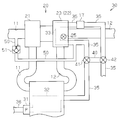
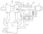
- the engine system according to the present embodiment is configured around an internal combustion engine 10.
- the internal combustion engine 10 is provided with a turbocharger 20 for supercharging the intake air in the intake passage 11 by pressure.
- the compressor 21 of the turbocharger 20 is attached to the intake passage 11 of the internal combustion engine 10
- the exhaust turbine 22 of the turbocharger 20 is attached to the exhaust passage 12.
- the turbocharger 20 is of an exhaust drive type in which a compressor wheel 21A provided in the compressor 21 and a turbine wheel 22A provided in the exhaust turbine 22 are connected.
- An exhaust purification device 13 for purifying exhaust is attached to the exhaust passage 12 downstream of the exhaust turbine 22 in the exhaust flow direction.
- a communication passage 24 is formed which communicates the upstream portion and the downstream portion of the exhaust passage 12 in the exhaust flow direction with respect to the turbine wheel 22 ⁇ / b> A.
- a waste gate valve 25 is attached to the turbine housing 23 for switching between a state where the flow of exhaust gas through the communication passage 24 is allowed and a state where it is blocked. When the waste gate valve 25 is opened, a part of the exhaust gas flows to the downstream side of the turbine wheel 22A so as to bypass the turbine wheel 22A through the communication passage 24.
- the engine system of the present embodiment is provided with a cooling system 30 for cooling the internal combustion engine 10 and the turbine housing 23 of the turbocharger 20.
- the cooling system 30 is provided with a water pump 31 of a type driven by the crankshaft 15 (see FIG. 1) of the internal combustion engine 10.
- the water pump 31 When the water pump 31 is activated as the internal combustion engine 10 is operated, the cooling water filled in the cooling system 30 is forcibly circulated.
- An engine cooling water channel 32 is formed inside the internal combustion engine 10, and a turbine cooling water channel 33 is formed inside the turbine housing 23.
- the cooling water passes through the engine cooling water channel 32 and the turbine cooling water channel 33.
- the route through which the cooling water circulates in the cooling system 30 includes a radiator 34, cooling water channels 35 and 36, and a bypass water channel 37.
- the radiator 34 is a heat exchanger for cooling the cooling water passing through the inside through heat exchange with the outside air.
- the cooling water passage 35 is a passage for guiding the cooling water flowing out from the engine cooling water passage 32 to the radiator 34, and a turbine cooling water passage 33 is attached in the middle of the cooling water passage 35.
- the cooling water passage 36 is a passage for returning the cooling water after passing through the radiator 34 to the engine cooling water passage 32.
- the bypass water passage 37 is a passage that communicates a portion of the cooling water passage 35 downstream of the turbine cooling water passage 33 in the cooling water flow direction with the cooling water passage 36 so as to bypass the radiator 34.
- a thermostat valve 38 is provided at the junction of the bypass water passage 37 and the cooling water passage 36.
- the thermostat valve 38 is configured such that the opening degree changes in accordance with the temperature of the cooling water that contacts the thermostat valve 38.
- the passage cross-sectional areas of the cooling water passage 36 and the bypass water passage 37 are changed by changing the opening degree of the thermostat valve 38, whereby the amount of cooling water flowing into the radiator 34 is adjusted.
- the bypass passage 40 extending around the turbine coolant passage 33 is attached to the coolant passage 35.
- a first switching valve 41 is provided at a portion where the bypass passage 40 branches from the cooling water passage 35, and a second switching valve 42 is provided at a portion where the bypass passage 40 joins the cooling water passage 35. It has been.
- the first switching valve 41 and the second switching valve 42 function as a switching unit, and the operation state thereof is selectively switched to one of the following “first operation mode” and “second operation mode”. ing.
- First operation mode Inflow of cooling water to the bypass passage 40 is prohibited and inflow of cooling water to the turbine cooling water channel 33 is allowed. That is, the engine cooling water channel 32 and the turbine cooling water channel 33 are connected in series in such a manner that the engine cooling water channel 32 is on the upstream side in the cooling water flow direction and the turbine cooling water channel 33 is on the downstream side in the cooling water flow direction.
- the cooling water of the cooling system 30 is allowed to flow in series from the engine cooling water channel 32 to the turbine cooling water channel 33.
- Second operation mode Inflow of cooling water to the turbine cooling water passage 33 is prohibited and inflow of cooling water to the bypass passage 40 is allowed. That is, the cooling water of the cooling system 30 is allowed to flow only in the engine cooling water channel 32 of the engine cooling water channel 32 and the turbine cooling water channel 33.
- the apparatus includes an electronic control unit 14 including, for example, a microcomputer.
- the electronic control device 14 receives detection signals from various sensors for detecting the operating state of the internal combustion engine 10.
- Examples of various sensors include a crank sensor for detecting the rotational speed of the crankshaft 15 (engine rotational speed NE), and an intake air amount for detecting the amount of intake air passing through the intake passage 11 (intake air amount GA).
- a sensor is provided.
- a temperature sensor 16 for detecting the temperature (THW) of the cooling water flowing out from the engine cooling water channel 32 and a flow rate sensor 17 for detecting the amount of cooling water (actual flow rate VW) flowing out of the turbine cooling water channel 33. Etc. are also provided.
- the temperature sensor 16 is attached in the vicinity of the connection portion of the engine cooling water passage 32 of the internal combustion engine 10 with the cooling water passage 35.
- the flow sensor 17 is attached to a portion of the cooling water passage 35 between the exhaust turbine 22 and the second switching valve 42. In the present embodiment, the flow sensor 17 corresponds to an outflow sensor.
- the electronic control unit 14 performs various calculations based on detection signals from various sensors, and based on the calculation results, the fuel injection control, the operation control of the waste gate valve 25, the first switching valve 41 and the second switching valve. Various controls such as operation control 42 are executed.
- the electronic control device 14 functions as a detection unit, a supply amount estimation unit, and a control unit.
- the turbine housing 23 may be cracked due to the influence of thermal stress generated during operation of the internal combustion engine 10.
- the cooling water may leak from the crack to the outside of the turbine cooling water passage 33, but also the cooling performance may be deteriorated, and the cooling water leaking from the crack may flow into the exhaust passage 12 of the internal combustion engine 10.
- the exhaust pressure suddenly rises due to evaporation of the cooling water in the exhaust passage 12, resulting in a decrease in the intake air amount, which may cause a decrease in output torque of the internal combustion engine 10.
- the exhaust gas purification device 13 is corroded or cracked due to this moisture, leading to early deterioration of the exhaust gas purification device 13. There is a fear.
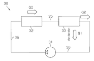
- FIG. 3 conceptually shows the flow rate of cooling water in each part of the cooling system 30.
- the amount of cooling water supplied to the turbine cooling water passage 33 (basic flow rate [in FIG. 3 Q0]) is substantially equal to the amount of cooling water passing through the engine cooling water passage 32, and substantially equal to the amount of cooling water pumped by the water pump 31.
- the coolant pumping amount of the water pump 31 can be accurately estimated based on the operating state of the internal combustion engine 10 (for example, the engine load KL, the engine rotational speed NE, and the coolant temperature THW). Therefore, the basic flow rate Q0 can also be accurately estimated based on the operating state of the internal combustion engine 10.
- the actual flow rate Q2 decreases when the turbine leakage abnormality occurs, and also decreases when an abnormality (engine abnormality abnormality) in which cooling water leaks from the inside of the engine cooling water channel 32 to the outside occurs. Therefore, in order to appropriately determine whether or not turbine leakage abnormality has occurred, after confirming that engine leakage abnormality has not occurred, determination of whether or not turbine leakage abnormality has occurred based on the basic flow rate Q0 and the actual flow rate Q2. It is desirable to do.
- the engine cooling water channel 32 is provided upstream of the turbine cooling water channel 33 in the flow direction of the cooling water, even if a turbine leakage abnormality occurs, the engine leakage abnormality does not occur and the engine cooling water channel 32 is not connected. If the flow rate of the cooling water passing therethrough is sufficiently secured, the temperature of the internal combustion engine 10 is suppressed within an appropriate range and does not become unnecessarily high. From this, it can be determined that the engine leakage abnormality does not occur because the temperature of the internal combustion engine 10 is kept low, and the internal combustion engine 10 is properly cooled.
- the amount of cooling water flowing inside the engine cooling water passage 32 decreases, so that the temperature of the internal combustion engine 10 is likely to rise.
- the amount of increase per hour becomes higher.
- the temperature of the cooling water flowing out from the engine cooling water passage 32 to the cooling water passage 35 which is an index value of the temperature of the internal combustion engine 10, is similarly increased.
- the rising speed of the coolant temperature THW at the time of occurrence of the engine leakage abnormality is obtained in advance based on the results of various experiments and simulations, and the above-mentioned engine leakage abnormality is caused based on the same speed.
- the above-described determination speed capable of accurately grasping the rapid increase in the temperature of the internal combustion engine 10 is determined and stored in the electronic control unit 14.
- the leakage amount Q1 is less than the determination amount, occurrence of a turbine leakage abnormality is not detected, and the switching valves 41 and 42 are held in the first operation mode.
- the cooling water circulates in the engine cooling water channel 32 and the turbine cooling water channel 33, and both the internal combustion engine 10 and the turbine housing 23 are cooled.
- the difference between the basic flow rate Q0 and the actual flow rate Q2 at the time of occurrence of the turbine leakage abnormality is obtained in advance from the results of various experiments and simulations, and the turbine leakage abnormality has occurred based on the difference. Is determined and stored in the electronic control unit 14 at an early stage with high accuracy.
- the leakage amount Q1 is equal to or larger than the determination amount, it is possible that a turbine leakage abnormality has occurred, and the switching valves 41 and 42 are switched to the second operation mode. At this time, the inflow of the cooling water to the turbine cooling water channel 33 is blocked, and the cooling water flows and circulates only in the engine cooling water channel 32. Accordingly, it is possible to suppress leakage of cooling water from the inside of the turbine cooling water passage 33 to the outside while maintaining the function of cooling the internal combustion engine 10. In addition, it is possible to suppress the shortage of the cooling water in the engine cooling water passage 32 and to reduce the intake air amount GA due to the evaporation of the cooling water in the exhaust passage 12. Can be maintained. Therefore, in the case of an engine system mounted on a vehicle as a drive source, the vehicle can be evacuated and carried to a maintenance shop.
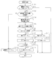
- FIG. 4 is a flowchart showing an execution procedure of the abnormality determination process, and a series of processes shown in this flowchart is executed by the electronic control unit 14 as an interrupt process at predetermined intervals.
- step S101 On the condition that both the engine abnormality flag and the turbine abnormality flag are turned off (step S101: NO), the rising speed of the cooling water temperature THW is equal to or lower than the determination speed. Is determined (step S102).
- step S102 When the rising speed of the cooling water temperature THW is higher than the determination speed (step S102: NO), the engine abnormality flag is turned on because there is a high possibility that the cooling water leaks from the engine cooling water channel 32. After (step S103), this process is temporarily terminated.
- step S101: YES the processing from step S102 to step S112 is not executed. Then, the operation control of the internal combustion engine 10 corresponding to the occurrence of the engine leakage abnormality is executed.
- step S102 when the rising speed of the cooling water temperature THW is equal to or lower than the determination speed (step S102: YES), it is highly likely that the engine leakage abnormality has not occurred, and the operating state of the internal combustion engine 10 (engine load KL, engine rotation).
- the basic flow rate Q0 is calculated (step S104). Further, the actual flow rate Q2 is detected by the flow rate sensor 17 (step S105).
- the relationship between the engine operating state determined by the engine load KL, the engine speed NE, and the coolant temperature THW and the basic flow rate Q0 is obtained in advance based on the results of various experiments and simulations, and the electronic control unit 14 Is remembered.
- the basic flow rate Q0 is calculated based on this relationship.
- the engine load KL an intake air amount GA, a fuel injection amount, or the like can be used.
- step S106 it is determined whether or not the amount obtained by subtracting the actual flow rate Q2 from the basic flow rate Q0 (the leakage amount Q1) is equal to or greater than the determination amount (step S106).
- the leakage amount Q1 is equal to or larger than the determination amount (step S106: YES)
- the abnormality flag is turned on (step S107), and the count value C is Incremented (step S108).
- step S102 YES
- step S106 YES
- step S108 the count value C is incremented (step S108).
- the count value C is a value corresponding to a period in which the initial value is “0”, the rising speed of the coolant temperature THW is equal to or less than the determination speed, and the leakage amount Q1 is equal to or greater than a predetermined amount.
- step S109 If this process is repeatedly executed and the count value C becomes larger than the predetermined value (step S109: YES), there is a very high possibility that no engine leakage abnormality has occurred, and the turbine that has been executed in the processes of steps S104 to S107.
- the turbine abnormality flag is turned on (step S110) assuming that the reliability of the determination result that the leakage abnormality has occurred is high. Thereafter, this process is temporarily terminated.
- a warning lamp is lit or an abnormality occurrence is displayed on the image display device to notify the occurrence of the abnormality, or the history of the occurrence of the turbine leakage abnormality is reported to the electronic control unit 14. Or may be memorized.
- step S109: NO if the rising speed of the cooling water temperature THW becomes higher than the determination speed (step S102: NO), an engine leakage abnormality may have occurred. Therefore, the engine abnormality flag is turned on (step S103), assuming that there is a high possibility that the increase in the leakage amount Q1 is due to the engine leakage abnormality. Thereafter, this process is temporarily terminated. In this case, the operation control of the internal combustion engine 10 corresponding to the occurrence of the engine leakage abnormality is executed.
- step S109: NO if the leakage amount Q1 becomes less than the determination amount (step S106: NO), the possibility that the turbine leakage abnormality has occurred is low.
- the abnormality flag is turned off (step S111), and the count value C is reset to “0” (step S112). Thereafter, this process is temporarily terminated.
- the cooling water flow rate in the engine cooling water passage 32 decreases and the function of cooling the internal combustion engine 10 decreases, and accordingly, the temperature of the internal combustion engine 10 rises, and as a result, the cooling water The temperature THW increases. As is clear from this, there is a slight time delay from when the engine leakage abnormality occurs until the coolant temperature THW rises.
- the determination of whether or not a turbine leakage abnormality has occurred Will be less accurate. That is, at this time, it is determined that the engine leakage abnormality has not occurred because the rising speed of the cooling water temperature THW is maintained below the determination speed (step S102: YES), and whether or not the turbine leakage abnormality has occurred is simply determined.
- the determination is executed (steps S104 to S106)
- step S104 when the rising speed of the coolant temperature THW is equal to or lower than the determination speed (step S102: YES), it is determined whether or not a turbine leakage abnormality has occurred (steps S104 to S106).
- step S106 When it is determined that a turbine leakage abnormality has occurred (step S106: YES), the switching valves 41 and 42 are switched to the second operation mode. Then, when the rising speed of the coolant temperature THW is maintained low for a predetermined period thereafter (step S109: YES), it is confirmed that no engine leakage abnormality has occurred, and occurrence of turbine leakage abnormality has occurred. Confirmed (step S110). By executing such processing, it is possible to quickly cope with the turbine leakage abnormality and appropriately determine whether or not the turbine leakage abnormality has occurred.
- the predetermined period (a period until the count value becomes a value greater than the predetermined value from “0”) is a turbine caused by a difference between the timing at which the engine leakage abnormality occurs and the timing at which the temperature of the internal combustion engine 10 rapidly increases.
- a sufficiently long period during which an erroneous determination of occurrence of leakage abnormality can be accurately suppressed is determined in advance and stored in the electronic control unit 14.
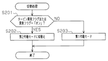
- FIG. 5 is a flowchart showing an execution procedure of the switching process, and the series of processes shown in this flowchart is executed by the electronic control unit 14 as an interrupt process at predetermined intervals.
- step S201: YES when either the abnormality flag or the turbine abnormality flag is turned on (step S201: YES), the operation mode of each switching valve 41, 42 is the second operation mode. (Step S202). On the other hand, when both the abnormality flag and the turbine abnormality flag are turned off (step S201: NO), the operation modes of the switching valves 41 and 42 are held in the first operation mode (step S203). Thus, after the operation mode of each switching valve 41 and 42 is operated according to the operation state of an abnormality flag or a turbine abnormality flag, this process is once complete
- each switching valve 41, 42 When the operation mode of each switching valve 41, 42 is the first operation mode and the basic flow rate Q0 is larger than the actual flow rate Q2 by the determination amount or more, the switching valves 41, 42 are switched to the second operation mode. I made it. As a result, the inflow of the cooling water to the turbine cooling water channel 33 is blocked, and the cooling water flows and circulates only in the engine cooling water channel 32. Therefore, the turbine cooling is performed while maintaining the function of cooling the internal combustion engine 10. The leakage of the cooling water from the inside of the water channel 33 to the outside can be suppressed.
- the switching valves 41 and 42 are switched to the second operation mode when it is detected that no engine leakage abnormality has occurred. Therefore, after confirming that no engine leakage abnormality has occurred, it is possible to grasp that a turbine leakage abnormality has occurred based on the basic flow rate Q0 and the actual flow rate Q2. it can.
- FIG. 6 shows a schematic configuration of the cooling device of the engine system of the present embodiment.
- the same components as those of the cooling device according to the first embodiment shown in FIG. 1 are denoted by the same reference numerals, and detailed description thereof is omitted.
- the engine system of the present embodiment includes an upstream side in the intake air flow direction from the compressor 21 in the intake passage 11 and the portion between the first switching valve 41 and the turbine cooling water passage 33 in the cooling water passage 35.
- a passage 50 communicating with this portion is attached.
- a differential pressure valve 51 is attached in the middle of the passage 50.
- the pressure P1 of the first portion on the cooling water passage 35 side of the differential pressure valve 51 in the passage 50 is compared with the pressure P2 of the second portion on the intake passage 11 side of the differential pressure valve 51 in the passage 50.
- JPA predetermined pressure
- the differential pressure valve 51 does not open when the cooling system 30 is operating normally and the cooling water temperature THW is adjusted within an appropriate temperature range. The valve is opened when the pressure of becomes excessively high. In the present embodiment, a differential pressure valve 51 that satisfies such requirements is employed.
- the supply of the cooling water to the turbine cooling water channel 33 is stopped, so that the cooling water in the turbine cooling water channel 33 is retained. And continue to be heated. If the internal pressure of the turbine cooling water channel 33 increases due to an increase in the cooling water temperature or evaporation of the cooling water accompanying this, the amount of cooling water leaking from the turbine cooling water channel 33 to the exhaust passage 12 may increase. . In this case, the intake air amount GA becomes very small due to an increase in the exhaust pressure, and the internal combustion engine 10 cannot be operated, or a large amount of moisture is supplied to the exhaust purification device 13 to increase the degree of deterioration. There is a fear.
- the pressure in the first portion of the passage 50 increases and the differential pressure valve 51 is opened. Steam generated by evaporation of the cooling water in the cooling water passage 33 is discharged to the intake passage 11 through the passage 50. Since the increase in the internal pressure of the turbine cooling water channel 33 can be suppressed through the operation of the differential pressure valve 51, the leakage amount of the cooling water from the turbine cooling water channel 33 to the exhaust passage 12 can be reduced. Reduction of the intake air amount GA and early deterioration of the exhaust purification device 13 can be suppressed.
- the passage 50 is connected to a portion of the intake passage 11 upstream of the compressor 21 in the intake flow direction, and the cooling water vapor is discharged into the intake passage 11 through the passage 50. Is done. Therefore, the cooling water vapor discharged into the intake passage 11 passes through the compressor 21.
- the compressor 21 of the turbocharger 20 has a structure that pumps intake air by rotation of the compressor wheel 21A, and the intake air passes through a scroll passage 26 that extends in a spiral shape around the compressor wheel 21A. Therefore, when the intake air containing the steam of the cooling water passes through the scroll passage 26, the scroll passage 26 functions as a centrifugal separator that separates moisture contained in the intake air. Then, the moisture separated from the intake air inside the scroll passage 26 is accumulated in a portion (a portion indicated by W in the figure) on the lower side in the vertical direction of the scroll passage 26.
- the compressor 21 functions as a centrifuge for separating moisture from the intake air.
- the waste gate valve It is driven so that 25 is the maximum opening. Therefore, at this time, although the cooling water leaked from the turbine cooling water passage 33 into the exhaust passage 12 evaporates, there is a risk of causing a sudden rise in the exhaust pressure, but an increase in the pressure in the exhaust passage 12 can be suppressed. . Therefore, a decrease in the intake air amount GA due to an increase in exhaust pressure can be suppressed, and a decrease in output torque of the internal combustion engine 10 can be suppressed.
- FIG. 8 shows a schematic configuration of the cooling device of the engine system of the present embodiment.
- the engine system of the present embodiment includes a portion between the first switching valve 41 and the turbine cooling water passage 33 in the cooling water passage 35 and the exhaust turbine 22 and the exhaust purification device 13 in the exhaust passage 12.
- a passage 60 communicating with the portion between the two is attached.
- a differential pressure valve 61 is attached in the middle of the passage 60.
- the pressure P3 in the third portion on the cooling water passage 35 side from the differential pressure valve 61 in the passage 60 is compared with the pressure P4 in the fourth portion on the exhaust passage 12 side from the differential pressure valve 61 in the passage 60.
- JPB predetermined pressure
- the differential pressure valve 61 does not open when the cooling system 30 is operating normally and the cooling water temperature THW is adjusted within an appropriate temperature range. On the other hand, a turbine leakage abnormality occurs and the inside of the turbine cooling water channel 33 is generated. The valve is opened when the pressure of becomes excessively high. In the present embodiment, a differential pressure valve 61 that satisfies such requirements is employed.
- a separator 62 for separating moisture contained in the gas passing through the passage 60 is attached to the passage 60 in the third portion on the cooling water passage 35 side from the differential pressure valve 61.
- the waste gate valve It is driven so that 25 is the maximum opening.
- the cooling water leaks into the exhaust passage 12 through the crack generated in the turbine cooling water passage 33 at this time and the cooling water evaporates, there is a possibility that the exhaust pressure may be rapidly increased.
- the increase in pressure inside can be suppressed. Therefore, a decrease in the intake air amount GA due to an increase in exhaust pressure can be suppressed, and a decrease in output torque of the internal combustion engine 10 can be suppressed.
- the waste gate valve 25 when the abnormality flag or the turbine abnormality flag is turned on, the waste gate valve 25 may not be driven so as to reach the fully open position. That is, at this time, the opening degree control of the waste gate valve 25 can be executed according to the operating state of the internal combustion engine 10.
- steps S107 to S107 in the abnormality determination process (FIG. 4) You may abbreviate
- the actual flow volume Q2 detected by the flow sensor 17 is suitable for the driving
- the basic flow rate Q0 can be set to a value in accordance with the actual situation, so that it is possible to accurately determine the turbine leakage abnormality based on the comparison between the basic flow rate Q0 and the actual flow rate Q2.
- step S106 in FIG. 4: YES in addition to satisfying the condition that “the basic flow rate Q0 is more than the determination amount than the actual flow rate Q2” (step S106 in FIG. 4: YES), “decrease in the actual flow rate Q2 per unit time”
- the abnormality flag may be turned on (step S107).
- the switching valves 41 and 42 may be switched to the second operation mode.
- the turbine leakage abnormality occurs, the actual flow rate Q2 rapidly decreases immediately after the occurrence. According to the above-described apparatus, it is possible to make the condition for determining the occurrence of the turbine leakage abnormality that the actual decrease in the actual flow rate Q2 has occurred.
- the calculation parameters used for calculating the basic flow rate Q0 are not limited to adopting the engine load KL, the engine rotation speed NE, and the cooling water temperature THW, but are related to the flow rate of the cooling water in the cooling system 30. Any value can be adopted as long as it is a value.
- the calculation parameter for example, an intake air temperature, an accelerator operation amount, a vehicle traveling speed, or the like can be employed.
- the method of detecting that no engine leakage abnormality has occurred is that the temperature of the internal combustion engine 10 becomes excessively high due to a decrease in cooling performance caused by leakage of cooling water from the engine cooling water channel 32.
- Any detection method can be adopted as long as it is a detection method that can determine that the image is likely to be excessively high.
- a detection method for example, the following (Detection Method 1) to (Detection Method 3) can be considered.
- the determination temperature in the following (detection method 1) and (detection method 2) a temperature for determining overheating of the internal combustion engine 10 can be set.
- Detection method 1 When the coolant temperature THW is equal to or higher than the determination temperature, it is detected that an engine leak abnormality has occurred. On the other hand, when the coolant temperature THW is less than the determination temperature, no engine leak abnormality has occurred. To detect. (Detection method 2) A temperature sensor for detecting the temperature of the internal combustion engine 10 is provided, and when the temperature of the internal combustion engine 10 detected by the temperature sensor is equal to or higher than a determination temperature, it is detected that an engine leakage abnormality has occurred. When the temperature of the internal combustion engine 10 is lower than the determination temperature, it is detected that no engine leakage abnormality has occurred.
- Detection method 3 While detecting that an engine leakage abnormality has occurred when the frequency of occurrence of knocking in the internal combustion engine 10 is equal to or greater than a predetermined value, when the frequency of occurrence of knocking is less than the predetermined value, the engine leakage abnormality has occurred. Detect that it has not occurred.
- the cooling water pressure that is an index value of the cooling water amount may be used.
- the pressure (basic pressure) of the cooling water supplied to the turbine cooling water channel 33 Is substantially equal to the pressure of the cooling water passing through the engine cooling water channel 32.
- the pressure of the cooling water passing through the engine cooling water channel 32 can be accurately estimated based on the operating state of the internal combustion engine 10. Therefore, the basic pressure can also be accurately estimated based on the operating state of the internal combustion engine 10.
- a pressure sensor for detecting the pressure of the cooling water is attached to a portion of the cooling water passage 35 between the exhaust turbine 22 and the second switching valve 42 instead of the flow rate sensor 17.
- This pressure sensor can also be attached in the vicinity of the cooling water outlet in the turbine cooling water channel 33.
- the pressure sensor corresponds to an outflow sensor.
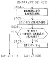
- Fig. 9 shows the execution procedure of the abnormality determination process of the modified example.
- the same process as the abnormality determination process shown in FIG. 4 is denoted by the same reference numeral, and detailed description thereof is omitted.
- the basic pressure is calculated based on the operating state of the internal combustion engine 10. (Step S304 in FIG. 9), the actual pressure is detected by the pressure sensor (Step S305).
- the presence / absence of occurrence of a turbine leak abnormality is grasped based on the flow rate of the cooling water, but the presence / absence of occurrence of a turbine leak abnormality can also be grasped based on the exhaust pressure or the exhaust flow rate.
- the supercharging performance of the turbocharger 20 is lowered due to the accompanying cooling performance reduction of the cooling system 30, and the exhaust pressure of the internal combustion engine 10 is reduced or the exhaust flow rate is reduced.
- the cooling water evaporates in the exhaust passage 12 and the internal pressure (exhaust pressure) of the exhaust passage 12 increases or the inside of the exhaust passage 12.
- the gas flow rate (exhaust flow rate) flowing through the flow increases.
- the exhaust pressure (basic exhaust pressure) and the exhaust flow rate (basic exhaust flow rate) of the internal combustion engine 10 when it is assumed that the cooling water does not leak from the turbine cooling water channel 33 are the operating state of the internal combustion engine 10 ( It can be accurately estimated based on the engine load KL and the engine speed NE). Therefore, a turbine leakage abnormality occurs when the actual exhaust pressure (actual exhaust pressure) detected by the pressure sensor is higher than the basic exhaust pressure by a first predetermined pressure or lower than a second predetermined pressure. You can grasp what you are doing. Further, a turbine leakage abnormality occurs when the actual exhaust flow rate (actual exhaust flow rate) detected by the flow sensor is greater than the basic predetermined exhaust flow rate by a first predetermined amount or less than the second predetermined amount. You can grasp what you are doing.
- a pressure sensor for detecting the exhaust pressure is attached to a portion of the exhaust passage 12 downstream of the exhaust turbine 22 in the exhaust flow direction.
- This pressure sensor may be attached to a portion of the exhaust passage 12 upstream of the exhaust turbine 22 in the exhaust flow direction.
- Fig. 10 shows the execution procedure of the abnormality determination process of the modified example.
- the same processes as the abnormality determination process shown in FIG. 4 are denoted by the same reference numerals, and detailed description thereof is omitted.
- the basic exhaust pressure is calculated based on the operating state of the internal combustion engine 10. Then, the actual exhaust pressure is detected by the pressure sensor (step S405).
- the presence / absence of occurrence of a turbine leakage abnormality is grasped based on the flow rate of the cooling water, but the turbine leakage abnormality is based on the internal pressure of the intake passage 11 (so-called intake pressure) and the intake air amount GA.
- intake pressure the internal pressure of the intake passage 11
- GA the intake air amount GA.
- the intake pressure (basic intake pressure) and the intake air amount (basic intake air amount) of the internal combustion engine 10 when it is assumed that no coolant leaks from the turbine cooling water passage 33 are the operating states of the internal combustion engine 10. It can be accurately estimated based on (engine speed NE or the like). Therefore, a turbine leakage abnormality occurs when the actual intake pressure (actual intake pressure) detected by the pressure sensor is higher than the basic intake pressure by a third predetermined pressure or lower than the fourth predetermined pressure. You can grasp what you are doing. Further, when the actual intake air amount GA detected by the intake air amount sensor is greater than the basic intake air amount by a third predetermined amount or less than the fourth predetermined amount, a turbine leakage abnormality has occurred. I can grasp that.
- a pressure sensor for detecting the intake pressure is provided in a portion of the intake passage 11 downstream of the compressor 21 in the intake flow direction.
- Fig. 11 shows the execution procedure of the abnormality determination process of the modified example.
- the same process as the abnormality determination process shown in FIG. 4 is denoted by the same reference numeral, and detailed description thereof is omitted.
- the basic intake pressure is calculated based on the operating state of the internal combustion engine 10.
- the actual intake pressure is detected by the pressure sensor (step S505).
- the presence / absence of occurrence of turbine leakage abnormality is grasped based on the flow rate of the cooling water, but the turbine is based on one of the exhaust pressure and the exhaust flow rate and one of the intake pressure and the intake air amount. You may make it grasp
- the switching valves 41 and 42 are switched to the second operation mode when the abnormality flag or the turbine abnormality flag is turned on.
- each of the switching valves 41 and 42 may be switched to the second operation mode when both of the following (Condition 1) and (Condition 2) are satisfied.
- (Condition 1) The internal combustion engine 10 is warming up. Specifically, the cooling water temperature THW is lower than a predetermined temperature.
- (Condition 2) The exhaust temperature is lower than a predetermined temperature.
- the engine system provided with the exhaust turbine 22 has a large heat capacity of the exhaust system, it is difficult for the temperature of the exhaust purification device 13 to rise after the internal combustion engine 10 is started. This improves the exhaust purification function of the exhaust purification device 13. It contributes to hindrance.
- the turbine housing 23 of the exhaust turbine 22 is cooled by the cooling water, the temperature increase rate of the exhaust purification device 13 after starting the engine tends to be slow.
- each switching is performed.
- the valves 41 and 42 are switched to the second operation mode, and the supply of cooling water to the turbine cooling water channel 33 is stopped.
- the degree to which the exhaust is cooled when passing through the exhaust turbine 22 can be reduced, so that the temperature of the exhaust purification device 13 can be raised early while suppressing a decrease in the exhaust temperature. It is possible to improve exhaust gas purification performance.
- the exhaust temperature in addition to using a value detected by a temperature sensor provided in the exhaust passage 12, a value estimated based on the operating state of the internal combustion engine 10 (engine load KL or engine speed NE) is used. You can also
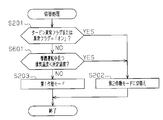
- FIG. 12 shows the execution procedure of the switching process of the modification.
- step S201: YES when the abnormality flag or the turbine abnormality flag is turned on (step S201: YES), the switching valves 41 and 42 are switched to the second operation mode (step S202).
- step S201: NO when both the abnormality flag and the turbine abnormality flag are turned off (step S201: NO), it is determined whether or not both (condition 1) and (condition 2) are satisfied (step S601).
- Step S601: YES it is determined whether or not both (condition 1) and (condition 2) are satisfied (Step S601: YES).
- Step S601: NO when one of (condition 1) and (condition 2) is not satisfied (step S601: NO), each switching valve 41, 42 is operated to the first operation mode (step S203).
- the cooling device described in each of the above embodiments is not limited to the cooling device in which the engine cooling water channel 32 and the turbine cooling water channel 33 are directly connected, and the engine cooling water channel, the turbine cooling water channel, and the engine cooling system are connected in parallel.
- the present invention can also be applied to a cooling device that has been used.
- the cooling water does not leak from the cooling system in a state where the switching valves 41 and 42 are in the first operation mode, whereby the cooling water flow state in the cooling system is changed to the operating state of the internal combustion engine 10. Therefore, the amount (basic flow rate) of the cooling water supplied to the turbine cooling water channel can also be accurately estimated based on the operating state of the internal combustion engine 10. Therefore, it is possible to determine whether or not a turbine leakage abnormality has occurred by detecting the amount of cooling water (actual flow rate) flowing out from the turbine cooling water channel using an outflow amount sensor and comparing it with the basic flow rate.
Landscapes
- Engineering & Computer Science (AREA)
- Chemical & Material Sciences (AREA)
- Combustion & Propulsion (AREA)
- Mechanical Engineering (AREA)
- General Engineering & Computer Science (AREA)
- Supercharger (AREA)
- Combined Controls Of Internal Combustion Engines (AREA)
Abstract
Description
以下、機関システムの冷却装置の第1実施形態について説明する。
以下、機関システムの冷却装置の第2実施形態について、第1実施形態との相違点を中心に説明する。
以下、機関システムの冷却装置の第3実施形態について、第1実施形態および第2実施形態との相違点を中心に説明する。
なお、上記各実施形態は、以下のように変更して実施してもよい。
(検出方法1)冷却水温度THWが判定温度以上であるときには機関漏れ異常が発生していることを検出する一方、冷却水温度THWが判定温度未満であるときには機関漏れ異常が発生してないと検出する。
(検出方法2)内燃機関10の温度を検出する温度センサを設け、同温度センサにより検出される内燃機関10の温度が判定温度以上であるときには機関漏れ異常が発生していることを検出する一方、同内燃機関10の温度が判定温度未満であるときには機関漏れ異常が発生してないと検出する。
(検出方法3)内燃機関10におけるノッキングの発生頻度が所定値以上であるときに機関漏れ異常が発生していることを検出する一方、ノッキングの発生頻度が所定値未満であるときには機関漏れ異常が発生していないと検出する。
(条件1)内燃機関10が暖機運転中であること。具体的には、冷却水温度THWが所定温度未満であること。
(条件2)排気温度が所定温度より低いこと。
Claims (5)
- 内燃機関とターボチャージャとを備える機関システムの冷却装置であって、同冷却装置は、
前記内燃機関の内部に形成された機関冷却水路と前記ターボチャージャの排気タービンのハウジング内部に形成されたタービン冷却水路とを有して冷却水が循環する冷却系と、
前記冷却系の冷却水が前記機関冷却水路および前記タービン冷却水路に流れることを許容する第1作動モードと、前記冷却系の冷却水が前記機関冷却水路および前記タービン冷却水路のうち同機関冷却水路のみを流れることを許容する第2作動モードとの何れかに選択的に切替えられる切替部と、
前記内燃機関の運転状態に基づいて前記タービン冷却水路に供給される冷却水量を推定する供給量推定部と、
前記タービン冷却水路から流出する冷却水量を検出する流出量センサと、
前記切替部の作動モードが前記第1作動モードであり、且つ前記供給量推定部により推定した冷却水量が前記流出量センサにより検出した冷却水量と比較して予め定められた判定量以上多いときに、前記切替部を前記第2作動モードに切替える制御部と、を備える機関システムの冷却装置。 - 請求項1に記載の機関システムの冷却装置において、
当該装置は、前記機関冷却水路から冷却水が漏れる異常が発生していないことを検出する検出部を備え、
前記制御部は、前記第2作動モードへの切替えを、前記検出部によって前記異常が発生していないことが検出されたことを条件として行う
機関システムの冷却装置。 - 請求項2に記載の機関システムの冷却装置において、
当該冷却装置は、前記機関冷却水路から流出する冷却水の温度を検出する温度センサを備え、
前記検出部は、前記温度センサにより検出した温度の上昇速度が判定速度以下で維持されるときに前記異常が発生していないことを検出する一方、前記上昇速度が前記判定速度を越えたときにはそれ以降において前記異常が発生していると検出する
機関システムの冷却装置。 - 内燃機関とターボチャージャとを備える機関システムの冷却装置の制御方法であって、前記冷却装置は、
前記内燃機関の内部に形成された機関冷却水路と前記ターボチャージャの排気タービンのハウジング内部に形成されたタービン冷却水路とを有して冷却水が循環する冷却系と、
前記冷却系の冷却水が前記機関冷却水路および前記タービン冷却水路に流れることを許容する第1作動モードと、前記冷却系の冷却水が前記機関冷却水路および前記タービン冷却水路のうち同機関冷却水路のみを流れることを許容する第2作動モードとの何れかに選択的に切替えられる切替部と、を備え、前記制御方法は、
前記内燃機関の運転状態に基づいて前記タービン冷却水路に供給される冷却水量を推定すること、
前記タービン冷却水路から流出する冷却水量を検出すること、および
前記切替部の作動モードが前記第1作動モードであり、且つタービン冷却水路に供給される冷却水量が前記タービン冷却水路から流出する冷却水量と比較して予め定められた判定量以上多いときに、前記切替部を前記第2作動モードに切替えること、を備える制御方法。 - 請求項4に記載の制御方法において、
前記制御方法は、前記機関冷却水路から冷却水が漏れる異常が発生していないことを検出すること、を備え、
前記切替部を前記第2作動モードに切替える条件が、前記異常が発生していないことが検出されたことを含む、制御方法。
Priority Applications (5)
| Application Number | Priority Date | Filing Date | Title |
|---|---|---|---|
| CN201380042932.6A CN104541032B (zh) | 2013-06-17 | 2013-06-17 | 内燃机系统的冷却装置及其控制方法 |
| JP2015522389A JP5930128B2 (ja) | 2013-06-17 | 2013-06-17 | 機関システムの冷却装置及びその制御方法 |
| US14/421,710 US9341106B2 (en) | 2013-06-17 | 2013-06-17 | Cooling apparatus for engine system and control method therefor |
| DE112013007167.3T DE112013007167B4 (de) | 2013-06-17 | 2013-06-17 | Kühlgerät für ein Kraftmaschinensystem und Steuerverfahren dafür |
| PCT/JP2013/066613 WO2014203312A1 (ja) | 2013-06-17 | 2013-06-17 | 機関システムの冷却装置及びその制御方法 |
Applications Claiming Priority (1)
| Application Number | Priority Date | Filing Date | Title |
|---|---|---|---|
| PCT/JP2013/066613 WO2014203312A1 (ja) | 2013-06-17 | 2013-06-17 | 機関システムの冷却装置及びその制御方法 |
Publications (1)
| Publication Number | Publication Date |
|---|---|
| WO2014203312A1 true WO2014203312A1 (ja) | 2014-12-24 |
Family
ID=52104083
Family Applications (1)
| Application Number | Title | Priority Date | Filing Date |
|---|---|---|---|
| PCT/JP2013/066613 Ceased WO2014203312A1 (ja) | 2013-06-17 | 2013-06-17 | 機関システムの冷却装置及びその制御方法 |
Country Status (5)
| Country | Link |
|---|---|
| US (1) | US9341106B2 (ja) |
| JP (1) | JP5930128B2 (ja) |
| CN (1) | CN104541032B (ja) |
| DE (1) | DE112013007167B4 (ja) |
| WO (1) | WO2014203312A1 (ja) |
Cited By (3)
| Publication number | Priority date | Publication date | Assignee | Title |
|---|---|---|---|---|
| KR20180100391A (ko) * | 2016-01-15 | 2018-09-10 | 스카니아 씨브이 악티에볼라그 | 차량 내 열교환기로 냉각제를 운송하는 냉각 시스템 제어 방법 |
| CN110344926A (zh) * | 2018-04-06 | 2019-10-18 | 现代自动车株式会社 | 发动机冷却剂分离器及具有该分离器的发动机冷却系统 |
| JP2022128332A (ja) * | 2021-02-22 | 2022-09-01 | トヨタ自動車株式会社 | 熱交換器の異常診断装置 |
Families Citing this family (12)
| Publication number | Priority date | Publication date | Assignee | Title |
|---|---|---|---|---|
| DE3532413A1 (de) | 1985-09-11 | 1987-03-12 | Uhde Gmbh | Vorrichtung zur erzeugung von synthesegas |
| JP6102867B2 (ja) * | 2013-10-17 | 2017-03-29 | トヨタ自動車株式会社 | 内燃機関の冷却装置および内燃機関の冷却装置の故障診断方法 |
| JP5971232B2 (ja) * | 2013-12-24 | 2016-08-17 | トヨタ自動車株式会社 | 機関システムの制御装置 |
| US10774771B2 (en) * | 2016-03-04 | 2020-09-15 | Ge Global Sourcing Llc | Engine control system for reducing particulate matter |
| EP3551863B1 (en) * | 2016-12-09 | 2024-05-01 | Volvo Truck Corporation | A cooling system valve |
| JP6397521B2 (ja) * | 2017-02-15 | 2018-09-26 | 本田技研工業株式会社 | 内燃機関の冷却水通路構造 |
| US20190093547A1 (en) * | 2017-09-22 | 2019-03-28 | GM Global Technology Operations LLC | Method and system for coolant temperature control in a vehicle propulsion system |
| CN107620630B (zh) * | 2017-11-03 | 2019-12-03 | 奇瑞汽车股份有限公司 | 发动机冷却液温度控制方法和系统 |
| CN109130865A (zh) * | 2018-10-18 | 2019-01-04 | 奇瑞新能源汽车技术有限公司 | 一种电动汽车液冷系统工作状态的检测系统及方法 |
| JP7070717B2 (ja) * | 2019-01-30 | 2022-05-18 | 株式会社アイシン | 車両用駆動装置 |
| CN110351987B (zh) * | 2019-07-15 | 2024-02-23 | 珠海格力电器股份有限公司 | 散热器、控制器、光伏用电设备和散热方法 |
| PL4127427T3 (pl) * | 2020-03-31 | 2024-10-28 | Rhapis s.r.l. | System oczyszczający spaliny silników spalinowych |
Citations (3)
| Publication number | Priority date | Publication date | Assignee | Title |
|---|---|---|---|---|
| JPH0332129U (ja) * | 1989-08-08 | 1991-03-28 | ||
| JPH0874574A (ja) * | 1994-08-31 | 1996-03-19 | Suzuki Motor Corp | 過給機付エンジンの冷却装置 |
| JP2008267257A (ja) * | 2007-04-19 | 2008-11-06 | Toyota Motor Corp | 過給機 |
Family Cites Families (12)
| Publication number | Priority date | Publication date | Assignee | Title |
|---|---|---|---|---|
| JPH0749036A (ja) | 1993-08-05 | 1995-02-21 | Aisan Ind Co Ltd | ターボチャージャ |
| JP2004116310A (ja) | 2002-09-24 | 2004-04-15 | Hitachi Ltd | 内燃機関の制御装置 |
| DE102005029322A1 (de) * | 2005-06-24 | 2006-12-28 | Behr Gmbh & Co. Kg | Vorrichtung zur Rückführung und Kühlung von Abgas für eine Brennkraftmaschine |
| JP2008019711A (ja) | 2006-07-10 | 2008-01-31 | Toyota Motor Corp | 内燃機関の過給機システム |
| DE102008014169A1 (de) * | 2007-04-26 | 2009-01-08 | Behr Gmbh & Co. Kg | Wärmetauscher, insbesondere zur Abgaskühlung, System mit einem Wärmetauscher zur Abgaskühlung, Verfahren zum Betreiben eines Wärmetauschers |
| JP2009047138A (ja) | 2007-08-22 | 2009-03-05 | Toyota Motor Corp | 内燃機関 |
| JP2010048187A (ja) | 2008-08-22 | 2010-03-04 | Toyota Motor Corp | エンジンの過給機システム |
| DE102010005824A1 (de) * | 2010-01-27 | 2011-07-28 | GM Global Technology Operations LLC, ( n. d. Ges. d. Staates Delaware ), Mich. | Flüssigkeitskühlsystem eines durch einen Turbolader aufgeladenen Verbrennungsmotors und Verfahren zur Kühlung eines Turbinengehäuses eines Turboladers |
| JP5316467B2 (ja) | 2010-04-06 | 2013-10-16 | トヨタ自動車株式会社 | 車両の制御装置 |
| IT1400446B1 (it) * | 2010-06-11 | 2013-05-31 | C R F Società Consortile Per Azioni | Motore a combustione interna sovralimentato |
| DE102011076457A1 (de) * | 2011-05-25 | 2012-11-29 | Ford Global Technologies, Llc | Kühlanordnung für eine aufladbare Brennkraftmaschine |
| JP2013002307A (ja) | 2011-06-13 | 2013-01-07 | Toyota Motor Corp | 過給機の冷却装置 |
-
2013
- 2013-06-17 CN CN201380042932.6A patent/CN104541032B/zh not_active Expired - Fee Related
- 2013-06-17 WO PCT/JP2013/066613 patent/WO2014203312A1/ja not_active Ceased
- 2013-06-17 DE DE112013007167.3T patent/DE112013007167B4/de not_active Expired - Fee Related
- 2013-06-17 US US14/421,710 patent/US9341106B2/en not_active Expired - Fee Related
- 2013-06-17 JP JP2015522389A patent/JP5930128B2/ja not_active Expired - Fee Related
Patent Citations (3)
| Publication number | Priority date | Publication date | Assignee | Title |
|---|---|---|---|---|
| JPH0332129U (ja) * | 1989-08-08 | 1991-03-28 | ||
| JPH0874574A (ja) * | 1994-08-31 | 1996-03-19 | Suzuki Motor Corp | 過給機付エンジンの冷却装置 |
| JP2008267257A (ja) * | 2007-04-19 | 2008-11-06 | Toyota Motor Corp | 過給機 |
Cited By (5)
| Publication number | Priority date | Publication date | Assignee | Title |
|---|---|---|---|---|
| KR20180100391A (ko) * | 2016-01-15 | 2018-09-10 | 스카니아 씨브이 악티에볼라그 | 차량 내 열교환기로 냉각제를 운송하는 냉각 시스템 제어 방법 |
| KR102114411B1 (ko) | 2016-01-15 | 2020-05-22 | 스카니아 씨브이 악티에볼라그 | 차량 내 열교환기로 냉각제를 운송하는 냉각 시스템 제어 방법 |
| CN110344926A (zh) * | 2018-04-06 | 2019-10-18 | 现代自动车株式会社 | 发动机冷却剂分离器及具有该分离器的发动机冷却系统 |
| JP2022128332A (ja) * | 2021-02-22 | 2022-09-01 | トヨタ自動車株式会社 | 熱交換器の異常診断装置 |
| JP7567548B2 (ja) | 2021-02-22 | 2024-10-16 | トヨタ自動車株式会社 | 熱交換器の異常診断装置 |
Also Published As
| Publication number | Publication date |
|---|---|
| DE112013007167T5 (de) | 2016-03-03 |
| CN104541032A (zh) | 2015-04-22 |
| JPWO2014203312A1 (ja) | 2017-02-23 |
| DE112013007167B4 (de) | 2019-09-26 |
| US9341106B2 (en) | 2016-05-17 |
| JP5930128B2 (ja) | 2016-06-08 |
| US20150219002A1 (en) | 2015-08-06 |
| CN104541032B (zh) | 2017-03-08 |
Similar Documents
| Publication | Publication Date | Title |
|---|---|---|
| JP5930128B2 (ja) | 機関システムの冷却装置及びその制御方法 | |
| US10590829B2 (en) | Control device for internal combustion engine and control method for cooling device | |
| CN102844554B (zh) | 空气流量计的故障诊断装置 | |
| WO2011021511A1 (ja) | 可変ウォータポンプの制御装置 | |
| US20090265086A1 (en) | Diagnosis Apparatus for Internal Combustion Engine | |
| JP5641975B2 (ja) | 内燃機関の冷却装置 | |
| JP6597667B2 (ja) | 内燃機関の制御装置 | |
| JP2015209782A (ja) | 内燃機関 | |
| JP2012149575A (ja) | 内燃機関の冷却装置 | |
| JP4561529B2 (ja) | 内燃機関冷却装置の故障検出システム | |
| JP4407589B2 (ja) | 内燃機関の冷却装置 | |
| JP5919664B2 (ja) | エンジンの制御装置 | |
| JP2013096357A (ja) | 内燃機関の制御装置 | |
| JP2006291815A (ja) | ターボチャージャの異常判定装置 | |
| JP2007270661A (ja) | サーモスタットの異常判定装置 | |
| JP6443325B2 (ja) | 内燃機関の制御装置 | |
| JP4985610B2 (ja) | ブローバイガス処理システムの異常判定装置 | |
| JP5146372B2 (ja) | 暖機判定装置 | |
| JP5821711B2 (ja) | 車両の制御装置 | |
| JP2016079842A (ja) | 車両のパワートレイン制御装置 | |
| JP2011001926A (ja) | エンジン制御装置 | |
| JP2013160067A (ja) | インタークーラ装置の異常検出装置及び内燃機関の制御装置 | |
| JP2015148213A (ja) | ターボチャージャの異常判定装置 |
Legal Events
| Date | Code | Title | Description |
|---|---|---|---|
| ENP | Entry into the national phase |
Ref document number: 2015522389 Country of ref document: JP Kind code of ref document: A |
|
| WWE | Wipo information: entry into national phase |
Ref document number: 14421710 Country of ref document: US |
|
| 121 | Ep: the epo has been informed by wipo that ep was designated in this application |
Ref document number: 13887483 Country of ref document: EP Kind code of ref document: A1 |
|
| WWE | Wipo information: entry into national phase |
Ref document number: 112013007167 Country of ref document: DE |
|
| 122 | Ep: pct application non-entry in european phase |
Ref document number: 13887483 Country of ref document: EP Kind code of ref document: A1 |