EP3551863B1 - A cooling system valve - Google Patents
A cooling system valve Download PDFInfo
- Publication number
- EP3551863B1 EP3551863B1 EP17818434.7A EP17818434A EP3551863B1 EP 3551863 B1 EP3551863 B1 EP 3551863B1 EP 17818434 A EP17818434 A EP 17818434A EP 3551863 B1 EP3551863 B1 EP 3551863B1
- Authority
- EP
- European Patent Office
- Prior art keywords
- cooling system
- valve
- radiator
- coolant
- combustion engine
- Prior art date
- Legal status (The legal status is an assumption and is not a legal conclusion. Google has not performed a legal analysis and makes no representation as to the accuracy of the status listed.)
- Active
Links
- 238000001816 cooling Methods 0.000 title claims description 220
- 239000002826 coolant Substances 0.000 claims description 175
- 238000002485 combustion reaction Methods 0.000 claims description 101
- 239000012530 fluid Substances 0.000 claims description 58
- 238000000034 method Methods 0.000 claims description 27
- 238000011144 upstream manufacturing Methods 0.000 claims description 19
- 238000004891 communication Methods 0.000 claims description 15
- 230000004044 response Effects 0.000 claims description 12
- 230000033001 locomotion Effects 0.000 claims description 8
- 230000005540 biological transmission Effects 0.000 claims description 6
- 230000008878 coupling Effects 0.000 description 19
- 238000010168 coupling process Methods 0.000 description 19
- 238000005859 coupling reaction Methods 0.000 description 19
- 230000001276 controlling effect Effects 0.000 description 5
- 239000003570 air Substances 0.000 description 4
- 238000010276 construction Methods 0.000 description 3
- 230000000717 retained effect Effects 0.000 description 3
- 230000006835 compression Effects 0.000 description 2
- 238000007906 compression Methods 0.000 description 2
- 238000006073 displacement reaction Methods 0.000 description 2
- 239000007788 liquid Substances 0.000 description 2
- 239000012080 ambient air Substances 0.000 description 1
- 230000000712 assembly Effects 0.000 description 1
- 238000000429 assembly Methods 0.000 description 1
- 230000009286 beneficial effect Effects 0.000 description 1
- 239000012809 cooling fluid Substances 0.000 description 1
- 230000002596 correlated effect Effects 0.000 description 1
- 230000003247 decreasing effect Effects 0.000 description 1
- 230000001419 dependent effect Effects 0.000 description 1
- 239000000463 material Substances 0.000 description 1
- 238000012986 modification Methods 0.000 description 1
- 230000004048 modification Effects 0.000 description 1
- 230000008569 process Effects 0.000 description 1
- 238000000926 separation method Methods 0.000 description 1
- 239000002699 waste material Substances 0.000 description 1
- XLYOFNOQVPJJNP-UHFFFAOYSA-N water Substances O XLYOFNOQVPJJNP-UHFFFAOYSA-N 0.000 description 1
Images


Classifications
-
- F—MECHANICAL ENGINEERING; LIGHTING; HEATING; WEAPONS; BLASTING
- F01—MACHINES OR ENGINES IN GENERAL; ENGINE PLANTS IN GENERAL; STEAM ENGINES
- F01P—COOLING OF MACHINES OR ENGINES IN GENERAL; COOLING OF INTERNAL-COMBUSTION ENGINES
- F01P11/00—Component parts, details, or accessories not provided for in, or of interest apart from, groups F01P1/00 - F01P9/00
- F01P11/04—Arrangements of liquid pipes or hoses
-
- F—MECHANICAL ENGINEERING; LIGHTING; HEATING; WEAPONS; BLASTING
- F01—MACHINES OR ENGINES IN GENERAL; ENGINE PLANTS IN GENERAL; STEAM ENGINES
- F01P—COOLING OF MACHINES OR ENGINES IN GENERAL; COOLING OF INTERNAL-COMBUSTION ENGINES
- F01P7/00—Controlling of coolant flow
- F01P7/14—Controlling of coolant flow the coolant being liquid
-
- F—MECHANICAL ENGINEERING; LIGHTING; HEATING; WEAPONS; BLASTING
- F01—MACHINES OR ENGINES IN GENERAL; ENGINE PLANTS IN GENERAL; STEAM ENGINES
- F01P—COOLING OF MACHINES OR ENGINES IN GENERAL; COOLING OF INTERNAL-COMBUSTION ENGINES
- F01P3/00—Liquid cooling
- F01P3/18—Arrangements or mounting of liquid-to-air heat-exchangers
-
- F—MECHANICAL ENGINEERING; LIGHTING; HEATING; WEAPONS; BLASTING
- F16—ENGINEERING ELEMENTS AND UNITS; GENERAL MEASURES FOR PRODUCING AND MAINTAINING EFFECTIVE FUNCTIONING OF MACHINES OR INSTALLATIONS; THERMAL INSULATION IN GENERAL
- F16K—VALVES; TAPS; COCKS; ACTUATING-FLOATS; DEVICES FOR VENTING OR AERATING
- F16K17/00—Safety valves; Equalising valves, e.g. pressure relief valves
- F16K17/20—Excess-flow valves
- F16K17/34—Excess-flow valves in which the flow-energy of the flowing medium actuates the closing mechanism
-
- F—MECHANICAL ENGINEERING; LIGHTING; HEATING; WEAPONS; BLASTING
- F16—ENGINEERING ELEMENTS AND UNITS; GENERAL MEASURES FOR PRODUCING AND MAINTAINING EFFECTIVE FUNCTIONING OF MACHINES OR INSTALLATIONS; THERMAL INSULATION IN GENERAL
- F16K—VALVES; TAPS; COCKS; ACTUATING-FLOATS; DEVICES FOR VENTING OR AERATING
- F16K31/00—Actuating devices; Operating means; Releasing devices
- F16K31/12—Actuating devices; Operating means; Releasing devices actuated by fluid
- F16K31/16—Actuating devices; Operating means; Releasing devices actuated by fluid with a mechanism, other than pulling-or pushing-rod, between fluid motor and closure member
- F16K31/163—Actuating devices; Operating means; Releasing devices actuated by fluid with a mechanism, other than pulling-or pushing-rod, between fluid motor and closure member the fluid acting on a piston
- F16K31/1635—Actuating devices; Operating means; Releasing devices actuated by fluid with a mechanism, other than pulling-or pushing-rod, between fluid motor and closure member the fluid acting on a piston for rotating valves
-
- F—MECHANICAL ENGINEERING; LIGHTING; HEATING; WEAPONS; BLASTING
- F16—ENGINEERING ELEMENTS AND UNITS; GENERAL MEASURES FOR PRODUCING AND MAINTAINING EFFECTIVE FUNCTIONING OF MACHINES OR INSTALLATIONS; THERMAL INSULATION IN GENERAL
- F16K—VALVES; TAPS; COCKS; ACTUATING-FLOATS; DEVICES FOR VENTING OR AERATING
- F16K31/00—Actuating devices; Operating means; Releasing devices
- F16K31/12—Actuating devices; Operating means; Releasing devices actuated by fluid
- F16K31/36—Actuating devices; Operating means; Releasing devices actuated by fluid in which fluid from the circuit is constantly supplied to the fluid motor
- F16K31/363—Actuating devices; Operating means; Releasing devices actuated by fluid in which fluid from the circuit is constantly supplied to the fluid motor the fluid acting on a piston
-
- F—MECHANICAL ENGINEERING; LIGHTING; HEATING; WEAPONS; BLASTING
- F16—ENGINEERING ELEMENTS AND UNITS; GENERAL MEASURES FOR PRODUCING AND MAINTAINING EFFECTIVE FUNCTIONING OF MACHINES OR INSTALLATIONS; THERMAL INSULATION IN GENERAL
- F16K—VALVES; TAPS; COCKS; ACTUATING-FLOATS; DEVICES FOR VENTING OR AERATING
- F16K5/00—Plug valves; Taps or cocks comprising only cut-off apparatus having at least one of the sealing faces shaped as a more or less complete surface of a solid of revolution, the opening and closing movement being predominantly rotary
- F16K5/06—Plug valves; Taps or cocks comprising only cut-off apparatus having at least one of the sealing faces shaped as a more or less complete surface of a solid of revolution, the opening and closing movement being predominantly rotary with plugs having spherical surfaces; Packings therefor
- F16K5/0647—Spindles or actuating means
-
- F—MECHANICAL ENGINEERING; LIGHTING; HEATING; WEAPONS; BLASTING
- F01—MACHINES OR ENGINES IN GENERAL; ENGINE PLANTS IN GENERAL; STEAM ENGINES
- F01P—COOLING OF MACHINES OR ENGINES IN GENERAL; COOLING OF INTERNAL-COMBUSTION ENGINES
- F01P11/00—Component parts, details, or accessories not provided for in, or of interest apart from, groups F01P1/00 - F01P9/00
- F01P11/02—Liquid-coolant filling, overflow, venting, or draining devices
- F01P11/0204—Filling
-
- F—MECHANICAL ENGINEERING; LIGHTING; HEATING; WEAPONS; BLASTING
- F01—MACHINES OR ENGINES IN GENERAL; ENGINE PLANTS IN GENERAL; STEAM ENGINES
- F01P—COOLING OF MACHINES OR ENGINES IN GENERAL; COOLING OF INTERNAL-COMBUSTION ENGINES
- F01P11/00—Component parts, details, or accessories not provided for in, or of interest apart from, groups F01P1/00 - F01P9/00
- F01P11/02—Liquid-coolant filling, overflow, venting, or draining devices
- F01P11/0276—Draining or purging
-
- F—MECHANICAL ENGINEERING; LIGHTING; HEATING; WEAPONS; BLASTING
- F01—MACHINES OR ENGINES IN GENERAL; ENGINE PLANTS IN GENERAL; STEAM ENGINES
- F01P—COOLING OF MACHINES OR ENGINES IN GENERAL; COOLING OF INTERNAL-COMBUSTION ENGINES
- F01P7/00—Controlling of coolant flow
- F01P7/14—Controlling of coolant flow the coolant being liquid
- F01P2007/146—Controlling of coolant flow the coolant being liquid using valves
-
- F—MECHANICAL ENGINEERING; LIGHTING; HEATING; WEAPONS; BLASTING
- F01—MACHINES OR ENGINES IN GENERAL; ENGINE PLANTS IN GENERAL; STEAM ENGINES
- F01P—COOLING OF MACHINES OR ENGINES IN GENERAL; COOLING OF INTERNAL-COMBUSTION ENGINES
- F01P2025/00—Measuring
- F01P2025/04—Pressure
-
- F—MECHANICAL ENGINEERING; LIGHTING; HEATING; WEAPONS; BLASTING
- F01—MACHINES OR ENGINES IN GENERAL; ENGINE PLANTS IN GENERAL; STEAM ENGINES
- F01P—COOLING OF MACHINES OR ENGINES IN GENERAL; COOLING OF INTERNAL-COMBUSTION ENGINES
- F01P2037/00—Controlling
-
- F—MECHANICAL ENGINEERING; LIGHTING; HEATING; WEAPONS; BLASTING
- F01—MACHINES OR ENGINES IN GENERAL; ENGINE PLANTS IN GENERAL; STEAM ENGINES
- F01P—COOLING OF MACHINES OR ENGINES IN GENERAL; COOLING OF INTERNAL-COMBUSTION ENGINES
- F01P2050/00—Applications
- F01P2050/22—Motor-cars
Definitions
- the present invention relates to a cooling system valve. Moreover, the present invention relates to a coolant conduit. Furthermore, the present invention relates to an internal combustion engine cooling system. Moreover, the present invention relates to an internal combustion engine assembly. Further, the present invention relates to a method for assembling an internal combustion engine cooling system. Additionally, the present invention relates to a method for fluidly disconnecting a radiator from a coolant passage and also to a method for performing service on an internal combustion engine cooling system.
- the invention can be applied in heavy-duty vehicles, such as trucks, buses and construction equipment. Although the invention will be described with respect to a truck, the invention is not restricted to this particular vehicle, but may also be used in other vehicles such as buses, construction equipment or seagoing vessels such as boats. Moreover, the present invention may be used in internal combustion engine assemblies not necessarily being located in or on a vehicle.
- An internal combustion engine may be adapted to be cooled by an internal combustion engine cooling system comprising a radiator in fluid communication with a coolant passage adapted to cool at least a portion of the internal combustion engine.
- coolant may flow from the radiator to the coolant passage where the coolant cools a portion of the internal combustion engine, as a consequence of which the coolant is heated, and the coolant is thereafter returned to the radiator in order to cool the coolant.
- the coolant may be a liquid.
- DE 15 76 703 A1 relates to a water cooled internal combustion engine for vehicles.
- FR 3 036 135 A1 relates to a cooling circuit of a vehicle engine comprising a cooling fluid outlet housing and a radiator, a first outlet pipe of the housing to the radiator, a first inlet line of the housing from the radiator which has an outlet pipe connecting it to the motor, a pump, circulating the fluid in the motor, being connected to the outlet pipe of the radiator and to a second outlet pipe of the housing.
- the circuit comprises, in the second outlet pipe, a flow control valve and, in the first inlet pipe in the housing, a non-return valve, decreasing or preventing the flow of fluid to the radiator when the control valve is closed.
- WO 2016/047304 A1 relates to a fluid control device, which can reduce the electric power required for the opening and closing operations of a fluid control valve is provided with the following: a valve body and a valve seat, one side of which is formed from a magnetic body and the other side of which is provided with a magnet so as to control the flow of a fluid by means of contact and separation, the valve body and valve seat being provided in a passage for the fluid; an energizing member that energizes the valve body toward the valve seat side; an electric pump for causing the fluid to pass through the passage; and a control part that, when opening and operating the valve body which is in a closed state and in contact with the valve seat, performs control to raise the electric pump output to a preset condition.
- GB1552987A relates to a non-return fluid valve arrangement having a valve closure member connected to a piston which is movable in a cylinder, and a selector device having a first inlet connected to experience a pressure related to the pressure at the inlet side of the non-return valve and a second inlet connected to experience a pressure related to the pressure at the outlet side of the non-return valve and having a selector member operable to connect an outlet from the selector device to which ever inlet is at the higher pressure, one side of the piston pressure on which tends to move the valve closure to a closed position communicating with the outlet of the selector device and the other side of the piston pressure on which tends to move the valve closure to an open position being selectively connectable by control valve means to the outlet of the selector device or to a region which is, during use of the arrangement, at a lower pressure than the pressure of the fluid controlled by the arrangement.
- WO 2015/197405 A1 relates to a valve device comprising a pilot valve and a main valve that is normally closed and has a check valve function.
- the main valve is laterally offset to said pilot valve.
- US 2002/166604 A1 relates to a coolant transfer machine for an automotive engine which machine includes first and second fluid transfer systems.
- the first system operated when the engine is not running, sequentially first removes at least a substantial portion of used coolant from the engine.
- the first system then collects in a used fluid container the used coolant as the used coolant is being removed and then replaces the removed used coolant with new coolant from a new fluid container.
- the second system operated when the engine is running, simultaneously displaces at least a substantial portion of used coolant in the engine with new coolant from the new fluid container and collects the displaced used coolant in the used fluid container.
- a manually operable switch has a first position that enables operation of the first fluid transfer system and a second position that enables operation of the second fluid transfer system.
- US4546792 A discloses a pressure actuated valve having a pivoting valve member according to the preamble of claim 1. According to its abstract, this document relates to a check valve having a straight-through flow passage wherein a ball-plug of a cylindrical geometry with a hemispherical end is pendulously confined in a cavity included in the valve body.
- the ball-plug has a through-hole with the central axis substantially passing through the center of a spherical surface including the hemispherical end of the ball-plug, which central axis substantially intersects the central axis of the ball-plug in an oblique angle.
- the ball-plug is pendulously confined in the cavity within the valve body by a trunnion in such a way that the ball plug is allowed to swing on a plane including the central axis of the flow passage of the check valve passing through the cavity confining the ball plug and the central axis of the ball plug.
- the through-hole included in the ball plug lines-up with the flow passage allowing straight-through flow for the fluid from one extremity to the other extremity of the check valve.
- US 2 998 223 A discloses a ball valve structure in which the ball and flow passage seals may be replaced without disconnecting the valve from its flow line.
- coolant needs to be removed from the internal combustion engine cooling system.
- a service person such as a mechanic
- drains off coolant may be a time-consuming process which adds to the total service operation time.
- the total service time generally is correlated to the service cost for the owner of the internal combustion engine.
- An object of the invention is to provide a device which may imply an appropriately low service operation time for at least one service operation for an internal combustion engine.
- the present invention relates to a cooling system valve for an internal combustion engine cooling system.
- the internal combustion engine cooling system comprises a radiator and a coolant passage adapted to cool at least a portion of an internal combustion engine.
- the cooling system valve is adapted to be located between the radiator and the coolant passage, as seen in an intended direction of flow from the radiator to the coolant passage.
- the cooling system valve is adapted to automatically assume each one of at least the following conditions:
- the above cooling system valve which is adapted to automatically assume each one of at least the above two conditions, implies the possibility to obtain a reduced risk for coolant leakage from the coolant passage to the ambient environment when the coolant passage is fluidly disconnected from the radiator.
- the above cooling system valve implies that the radiator may be fluidly disconnected from the coolant passage without necessarily obtaining a flow of coolant from the coolant passage.
- the above cooling system valve implies that at least a portion of the coolant in the coolant passage may be retained during the service operation. Thereafter, when the service operation is completed, the time consumption for replenishing coolant to the cooling system may also be kept appropriately low since coolant has been retained in the cooling system, in particular in the coolant passage thereof, during the service operation.
- Examples of service operations not requiring that the complete cooling system be emptied of coolant prior to the operation can be carried out include for instance: replacing or removing at least one of the following components of an internal combustion engine cooling system radiator, fan shroud, fan ring, expansion tank and radiator upper hose.
- the total service operation time for an internal combustion engine may be kept appropriately low.
- the coolant may retained in the cooling system even during one or more types of service operations implies an appropriately low waste of coolant.
- the cooling system valve may be adapted to automatically assume each one of the conditions in dependence of an operational state of the internal combustion engine.
- the above ability implies that the cooling system valve may be adapted to automatically assume each one of the conditions for certain predetermined operational state(s) of the internal combustion engine.
- the cooling system valve may be adapted to assume the closed condition when the internal combustion engine is not running.
- the operational state may comprise at least one of the following: a coolant temperature, a coolant flow rate, a coolant pressure and an indication whether or not the internal combustion engine is running.
- the cooling system valve is adapted to automatically assume each one of the conditions in dependence of a pressure applied to at least a portion of the cooling system valve.
- the cooling system valve may for instance be adapted to assume the closed condition when the pressure applied to at least a portion of the cooling system valve is below a predetermined pressure threshold, for instance when the pressure corresponds to atmospheric pressure.
- the valve may assume the closed condition when the cooling system valve is disconnected from a portion of the internal combustion engine cooling system such that at least a portion of the cooling system valve is exposed to the air ambient of the cooling system.
- the cooling system valve is adapted to automatically assume each one of the conditions in dependence of a pressure upstream the cooling system valve, as seen in an intended direction of flow from the radiator to the coolant passage.
- a portion of the cooling system valve facing the radiator is prone to being exposed to the air ambient of the cooling system.
- an upstream portion of the cooling system valve may be exposed to the ambient air.
- the cooling system valve is adapted to automatically assume the closed condition when the pressure upstream the cooling system valve is equal to or below a predetermined threshold value.
- the predetermined threshold value may correspond to atmospheric pressure or be a factor multiplied by the atmospheric pressure.
- the factor may be within the range of 1 - 1.5.
- the cooling system valve comprises a valve member and a valve housing, the valve member being moveable relative to the valve housing to thereby obtain the open and closed conditions, the position of the valve member relative to the valve housing being controlled by the pressure upstream the cooling system valve.
- valve member is adapted to pivot relative the valve housing.
- the ability to pivot the valve member implies that the cooling system valve can be made relatively compact.
- the cooling system valve comprises a valve member actuator, adapted to move the valve member relative to the valve housing.
- the cooling system valve further comprises a pilot pressure conduit in fluid communication with the valve member actuator.
- the pilot pressure conduit may be used for controlling the condition of the valve.
- the pilot pressure conduit may be in fluid communication with a fluid control line such that the condition of the cooling system valve is controlled by controlling the pressure in the fluid control line.
- the pilot pressure conduit fluidly connects the valve member actuator to a portion of the cooling system valve upstream the valve member, as seen in an intended direction of flow from the radiator to the coolant passage.
- the cooling system valve when the cooling system valve is connected to the cooling system, coolant may enter the pilot pressure conduit and the coolant pressure consequently controls the condition of the cooling system valve.
- the opening or closing of the valve may be controlled in dependence of the coolant pressure.
- the cooling system valve may be such that when the cooling system valve is connected to the cooling system such that coolant is present in the pilot pressure conduit, the cooling system valve is in the open condition, and when the cooling system valve is disconnected from at least a portion of the cooling system such that the pilot pressure conduit is in fluid communication with the environment ambient of the cooling system, for instance thereby filling the pilot pressure conduit with air, the cooling system valve assumes the closed condition.
- the cooling system valve comprises an actuator chamber in fluid communication with the pilot pressure conduit, at least a portion of the valve member actuator delimiting the actuator chamber such that the valve member actuator can move in response to a pressure in the actuator chamber.
- the actuator chamber implies that the cooling system valve may be relatively compact.
- valve member actuator is fixedly connected to the valve member, the valve member actuator being adapted to pivot in response to a pressure in the actuator chamber.
- the fixed connection between the valve member actuator and the valve member implies a robust assembly for controlling the condition of the cooling system valve with an appropriately low number of moving parts.
- valve member actuator is connected to the valve member via a transmission arrangement transferring a rectilinear motion of the valve member actuator into a pivot motion of the valve member, the valve member actuator being adapted to move rectilinearly in response to a pressure in the actuator chamber.
- the above transmission arrangement implies an appropriate versatility in the position of the actuator chamber relative to the valve member.
- valve member actuator is adapted to accommodate fluid fed from the pilot pressure conduit, the valve member actuator being adapted to deform in response to a pressure of the fluid accommodated in the valve member actuator.
- valve member actuator is fixedly connected to the valve member.
- the cooling system valve comprises a biasing means adapted to bias the valve member towards the closed condition.
- a second aspect of the present invention relates to a coolant conduit adapted to form part of an internal combustion engine cooling system comprising a radiator and a coolant passage adapted to cool at least a portion of an internal combustion engine.
- the coolant conduit is adapted to be located between the radiator and the coolant passage, as seen in an intended direction of flow from the radiator to the coolant passage.
- the coolant conduit comprises a cooling system valve according to the first aspect of the present invention.
- a third aspect of the present invention relates to an internal combustion engine cooling system comprising a radiator and a coolant passage adapted to cool at least a portion of an internal combustion engine.
- the internal combustion engine cooling system comprises a cooling system valve according to the first aspect of the present invention and/or a coolant conduit according to the second aspect of the present invention.
- the cooling system valve is located between the radiator and the coolant passage, as seen in an intended direction of flow from the radiator to the coolant passage.
- the internal combustion engine cooling system further comprises a coolant pump adapted to circulate coolant in the internal combustion engine cooling system.
- the coolant pump is located between the radiator and the coolant passage, as seen in an intended direction of flow from the radiator to the coolant passage.
- the cooling system valve is located between the radiator and the coolant pump, as seen in an intended direction of flow from the radiator to the coolant passage.
- a fourth aspect of the present invention relates to an internal combustion engine assembly comprising an internal combustion engine and an internal combustion engine cooling system according to the third aspect of the present invention.
- a fifth aspect of the present invention relates to vehicle comprising an internal combustion engine assembly according to the fourth aspect of the present invention.
- a sixth aspect of the present invention relates to a method for assembling a combustion engine cooling system.
- the combustion engine cooling system comprises a radiator and a coolant passage adapted to cool at least a portion of an internal combustion engine.
- the method comprises connecting the radiator to the coolant passage by means of a coolant conduit according to the second aspect of the present invention.
- a seventh aspect of the present invention relates to a method for fluidly disconnecting a radiator from a coolant passage adapted to cool at least a portion of an internal combustion engine cooling system, wherein, during operating conditions of the internal combustion engine cooling system, the radiator is fluidly connected to the coolant passage by means of a coolant conduit according to the second aspect of the present invention.
- the method comprises disconnecting the coolant conduit from the radiator, whereby the cooling system valve closes automatically.
- An eighth aspect of the present invention relates to a method for performing service on an internal combustion engine cooling system comprising a radiator, a coolant passage adapted to cool at least a portion of an internal combustion engine and a coolant conduit.
- the method comprises fluidly disconnecting the radiator from the coolant passage in accordance with the seventh aspect of the present invention.
- the invention will be described below for a vehicle in the form of a truck 10 such as the truck illustrated in Fig. 1 .
- the truck 10 should be seen as an example of a vehicle which could comprise a cooling system valve, a coolant conduit and/or an internal combustion engine cooling system according to the present invention.
- the present invention may be implemented in a plurality of different types of vehicles. Purely by way of example, the present invention could be implemented in a truck, a tractor, a car, a bus, a seagoing vessel such as a ship or a boat, a work machine such as a wheel loader or an articulated hauler, or any other type of construction equipment.
- the present invention may be implemented in an internal combustion that need not be associated with any vehicle.
- the Fig. 1 vehicle 10 comprises an internal combustion engine cooling system 12.
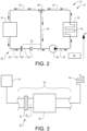
- Fig. 2 is a schematic side view of an internal combustion engine cooling system 12 comprising a radiator 14 and a coolant passage 16 adapted to cool at least a portion of an internal combustion engine 18.
- the internal combustion engine cooling system 12 and the internal combustion engine 18 may form an internal combustion engine assembly 13.
- the coolant passage 16 may comprise one or more conduits in an engine block (not shown) of the internal combustion engine 18 and/or one or more conduits external to the internal combustion engine 18 and arranged to be in thermal communication therewith.
- Fig. 2 illustrates that the internal combustion engine cooling system 12 has an extension in a vertical direction V and that the assembly 12 comprises a coolant feeding conduit assembly 20 for guiding coolant from the radiator 14 to the coolant passage 16, and a fluid returning conduit assembly 22 for guiding coolant from the coolant passage 16 to the radiator 14.
- the lowest point of the coolant feeding conduit assembly 20 may be lower than the highest point of the fluid returning conduit assembly 22.
- Fig. 2 illustrates a cooling system valve 24 adapted to be located between the radiator 14 and the coolant passage 16, as seen in an intended direction of flow from the radiator 14 to the coolant passage 16.
- the cooling system valve 24 may be located in the coolant feeding conduit assembly 20.
- the intended direction of flow may for instance be achieved by a pump 26.
- the pump may be located between the radiator 14 to the coolant passage 16, such as in the Fig. 2 coolant feeding conduit assembly 20.
- the portion of the internal combustion engine cooling system 12 connecting the radiator 14 to the coolant passage 16 generally is the lowermost portion of the assembly 12.
- the cooling system valve 24 may be located between the radiator 14 and the coolant pump 26.
- the Fig. 2 embodiment also comprises a thermostat valve 28 located between the coolant passage 16 and the radiator 14, as seen in an intended direction of flow from the coolant passage 16 to the radiator 14.
- the thermostat valve 28 may be located in the Fig. 2 fluid returning conduit assembly 22.
- the purpose of the thermostat valve 28 is to bypass the radiator 14 under certain conditions, for instance if the coolant temperature is lower than a predetermined threshold temperature.
- the thermostat valve 28 may be in fluid communication with a bypass conduit 30 and the thermostat valve 28 may be arranged to selectively provide a fluid communication between a portion of the fluid returning conduit assembly 22 and the bypass conduit 30.
- the cooling system valve 24 is distinct from the thermostat valve 28.
- thermostat valve 28 may be omitted.
- the internal combustion engine cooling system 12 may also comprise a coupling 32 connecting a first feeding conduit assembly portion 20' to a second feeding conduit assembly portion 20".
- the coupling 32 is located between the radiator 14 and the cooling system valve 24, as seen in an intended direction of flow from the radiator 14 to the coolant passage 16.
- the coupling 32 may assume a disconnected condition, in which the first feeding conduit assembly portion 20' is fluidly disconnected from the second feeding conduit assembly portion 20", and a connected condition, in which the a first feeding conduit assembly portion 20' is fluidly connected to the second feeding conduit assembly portion 20".
- the second feeding conduit assembly portion 20" and the cooling system valve 24 may form part of a coolant conduit 34.
- the cooling system valve 24 is adapted to automatically assume each one of at least the following conditions:
- the ability to assume any one of the above conditions is beneficial in a least the following situations.
- the cooling system valve 24 may assume an open condition, thus allowing coolant to flow from the radiator 14 to the coolant passage 16 to thereby enable the internal combustion engine 18 to be appropriately cooled.
- certain service operations may require that the coupling 32 assumes a disconnected condition, thereby disconnecting the first feeding conduit assembly portion 20' from the second feeding conduit assembly portion 20".
- Examples of service operations requiring that the coupling 32 assumes a disconnected condition include for instance replacing or removing at least one of the following components of an internal combustion engine cooling system: the radiator 14, a fan shroud (not shown), a fan ring (not shown), an expansion tank (not shown) and the fluid returning conduit assembly 22.
- the cooling system valve 24 automatically assumes each one of at least the closed condition and the open condition. As such, an operator, such as a mechanic, need not actuate the cooling system valve 24 separately, e.g. prior to actuating the coupling 32, so as to assume its disconnected condition.
- the cooling system valve 24 is illustrated as a non-return valve in the Fig. 2 embodiment. However, as will be elaborated on hereinabove, a plurality of various embodiments of the cooling system valve 24 is envisioned.
- the cooling system valve 24 may be adapted to automatically assume each one of the conditions, i.e. open or closed, in dependence of an operational state of the internal combustion engine 18.
- the cooling system valve 24 may be adapted to receive one or more signals from the internal combustion engine 18 or a control unit 36, such as an electronic control unit, controlling the operation of the internal combustion engine 18.
- control signals may be electric, hydraulic, pneumatic or mechanical control signals or any combination thereof.
- the cooling system valve 24 may be adapted to assume a condition in response to the signal or signals received.
- the operational state may comprise at least one of the following: a coolant temperature, a coolant flow rate, a coolant pressure and an indication whether or not the internal combustion engine is running.
- the cooling system valve 24 may be adapted to automatically assume each one of the conditions in dependence of a pressure applied to at least a portion of the cooling system valve 24.
- the cooling system valve 24 is adapted to automatically assume each one of the conditions in dependence of a pressure P u upstream the cooling system valve 24, as seen in an intended direction of flow from the radiator 14 to the coolant passage 16.
- the feeding conduit assembly 20 when the coupling 32 assumes its connected condition, the feeding conduit assembly 20 generally is filled with coolant, resulting in that the pressure P u upstream the cooling system valve 24 corresponds to the liquid column of the coolant located directly upstream the cooling system valve 24.
- the portion of the feeding conduit assembly 20 located between the coupling 32 and the cooling system valve 24, i.e. the second feeding conduit assembly portion 20 is exposed to the environment ambient of the coolant feeding conduit assembly 20.
- the portion of the feeding conduit assembly 20 located between the coupling 32 and the cooling system valve 24 is filled with air.
- the pressure P u upstream the cooling system valve 24 generally is lower than when the coupling 32 assumes its connected condition and such a pressure difference may be used for controlling the condition of the cooling system valve 24.
- the cooling system valve 24 may be adapted to automatically assume the closed condition when the pressure P u upstream the cooling system valve 24 is equal to or below a predetermined threshold value.
- Fig. 4a to Fig. 6b illustrate embodiments of the cooling system valve 24, the conditions of which are controllable by the pressure P u upstream the cooling system valve 24.
- the Fig. 4a to Fig. 6b embodiments have a plurality of features in common and the common features will be presented with reference to the Fig. 4a and Fig. 4b embodiment.
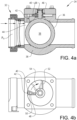
- the Fig. 4a and Fig. 4b embodiment comprises a valve member 36 and a valve housing 38 wherein the valve member 36 is moveable relative to the valve housing 38 to thereby obtain the open and closed conditions.
- the position of the valve member 36 relative to the valve housing 38 is controlled by the pressure P u upstream the cooling system valve 24.
- the valve member 36 is adapted to pivot relative the valve housing 38.
- the cooling system valve 24 comprises a valve member actuator 40, adapted to move the valve member 36 relative to the valve housing 38.
- the valve member actuator 40 is fixedly connected to the valve member 36 and the valve member actuator 40 is adapted to pivot in response to a pressure on the actuator chamber 48.
- the valve member 36 may comprise a fluid passage 56, such as an opening, extending through the valve member 36.
- the fluid passage 56 may be located and oriented such that fluid may flow through the fluid passage 56 when the cooling system valve 24 assumes the open condition whereas fluid cannot flow through the fluid passage 56 when the cooling system valve 24 assumes the closed condition.
- the valve member 36 may be substantially spherically shaped and the fluid passage 56 may extend therethrough such that when the cooling system valve 24 assumes the open condition, the fluid passage 56 is oriented with its main extension substantially parallel to the intended direction of flow through the cooling system valve 24 and when the cooling system valve 24 assumes the closed condition, the fluid passage 56 is oriented with its main extension substantially perpendicular to the intended direction of flow through the cooling system valve 24.
- Fig. 4a illustrates the cooling system valve 24 in the closed position.
- the Fig. 4a cooling system valve 24 further comprises a pilot pressure conduit 42 in fluid communication with the valve member actuator 40.
- the pilot pressure conduit 42 is adapted to be in fluid communication with a portion 44 of the cooling system valve upstream the valve member 36, as seen in an intended direction of flow from the radiator to the coolant passage (not shown in Fig. 4a ).
- the pilot pressure conduit may be in fluid communication with another fluid source, such as a pilot pressure fluid source (not shown), external of the coolant feeding conduit assembly 20, which pilot pressure fluid source feeds fluid at a pilot pressure to the valve member actuator 40.
- Fig. 4a illustrates that the cooling system valve 24 illustrated therein comprises a lid 46 such that the valve member actuator 40 is located between the valve member 36 and the lid 46.
- Fig. 4b is a top view of the Fig. 4a but in Fig. 4b , the lid 46 has been removed.
- the cooling system valve 24 comprises the actuator chamber 48 in fluid communication with the pilot pressure conduit 42.
- the actuator chamber 48 may be a cavity in the valve housing 38.
- the actuator chamber 48 may be drilled, milled or cut into the valve housing material, such that the actuator chamber 48 is confined by end surfaces 50, 52 of the valve housing 38.
- valve member actuator 40 delimits the actuator chamber 48 such that the valve member actuator 40 can move in response to a pressure in the actuator chamber 48.
- the Fig. 4b valve member actuator 40 will rotate in a clockwise direction, as indicated by arrow 54 in Fig. 4b , as a consequence of which the valve member 36 will also rotate.
- the valve member actuator 40 and the valve member 36 will move in concert such that the cooling system valve 24 assumes the open condition.
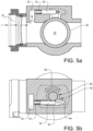
- FIG. 5a and 5b Another embodiment of the cooling system valve 24 is illustrated in Fig. 5a and 5b .
- Fig. 5a and Fig. 5b features that are similar to the features of the Fig. 4a and Fig. 4b embodiment are assigned the same reference numerals, but the features or their intended functions are repeated in the below presentation of the Fig. 5a and Fig. 5b embodiment.
- the valve member actuator 40 illustrated therein is connected to the valve member 36 via a transmission arrangement 58 transferring a rectilinear motion of the valve member actuator 40 into a pivot motion of the valve member 36.
- the transmission arrangement 58 is exemplified as a pinion 60, for instance fixedly connected to the valve member 36, and a rack 62, for instance fixedly connected to or forming part of the valve member actuator 40.
- the cooling system valve 24 may comprise a biasing means adapted to bias the valve member 36 towards the closed condition.
- the biasing means may be such that when the pressure in the pilot pressure conduit 42 is below a predetermined pressure threshold level, the biasing means can move the valve member 36 such that the cooling system valve 24 assumes its closed condition.
- the biasing means is implemented as a torsion spring 68.
- the Fig. 4a biasing means may connect the valve housing 38 to the valve member 36.
- the biasing means is implemented as a tension spring 70, such as a coil spring, connecting the valve housing 38 to the rack 62.
- the Fig. 5a and Fig. 5b embodiment may comprise a compression spring (not shown) between the rack 62 and the valve housing 38, such a compression spring may for instance be located to the right of the rack 62 in Fig. 5b .
- FIG. 6a and 6b Another embodiment of the cooling system valve 24 is illustrated in Fig. 6a and 6b .
- Fig. 6a and Fig. 6b features that are similar to the features of the Fig. 4a and Fig. 4b embodiment are assigned the same reference numerals, but the features or their intended functions are repeated in the below presentation of the Fig. 6a and Fig. 6b embodiment.
- valve member actuator 40 is adapted to accommodate fluid fed from the pilot pressure conduit 42. Moreover, the valve member actuator 40 is adapted to deform in response to a pressure of the fluid accommodated in the valve member actuator 40.
- the Fig. 6a and Fig. 6b valve member actuator 40 may for instance comprise a flexible conduit with a radial inner portion 72 fixedly connected to the valve member 36 and a radial outer portion 74 fixedly connected to the valve housing 38.
- the valve member actuator 40 may have a coiled shape around the rotational centre of the valve member 36 such that when the pressure in the valve member actuator 40 is above a predetermined threshold pressure, the valve member actuator 40 unwinds and thereby rotates the valve member 36.
- the above-discussed coolant conduit 34 comprising a cooling system valve 24, may be used in a method for assembling a combustion engine cooling system 12, such as the Fig. 2 cooling system 12.
- the method comprises connecting the radiator 14 to the coolant passage 16 by means of the coolant conduit 34.
- the above method may be used for constructing a new cooling system 12.
- the above method may also form a part of a procedure for modifying a cooling system 12.
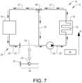
- Fig. 7 illustrating an existing cooling system 12, having a coolant transport conduit 76, forming a part of the first feeding conduit assembly portion 20' and being located between the radiator 14 and the pump 26.
- Such an existing cooling system 12 may be modified by replacing the coolant transport conduit 76 by a coolant conduit 34 according to the present invention.
- the coolant conduit 34 may comprise a coupling 32, or at least a portion of such a coupling, in order to enable that the coolant conduit 34 forms part of the first feeding conduit assembly portion 20' in a time-efficient manner. It is envisioned that embodiments of the coolant conduit 34 may be constituted by the cooling system valve 24 and the coupling 32.
- An internal combustion engine cooling system 12 may be used in a method for fluidly disconnecting a radiator 14 from a coolant passage 16 adapted to cool at least a portion of an internal combustion engine 18.
- the radiator 14 is fluidly connected to the coolant passage 16 by means of a coolant conduit 34, as discussed hereinabove.
- the method comprises disconnecting the coolant conduit 34 from the radiator 14 whereby the cooling system valve 24 of the coolant conduit 34 closes automatically.
- the above method may preferably be used in a method for performing service on an internal combustion engine cooling system 12 in accordance with the present invention.
- the method comprises fluidly disconnecting the radiator from the coolant passage in accordance with the seventh aspect of the present invention.
Landscapes
- Engineering & Computer Science (AREA)
- General Engineering & Computer Science (AREA)
- Mechanical Engineering (AREA)
- Chemical & Material Sciences (AREA)
- Combustion & Propulsion (AREA)
- Cooling, Air Intake And Gas Exhaust, And Fuel Tank Arrangements In Propulsion Units (AREA)
- Temperature-Responsive Valves (AREA)
Description
- The present invention relates to a cooling system valve. Moreover, the present invention relates to a coolant conduit. Furthermore, the present invention relates to an internal combustion engine cooling system. Moreover, the present invention relates to an internal combustion engine assembly. Further, the present invention relates to a method for assembling an internal combustion engine cooling system. Additionally, the present invention relates to a method for fluidly disconnecting a radiator from a coolant passage and also to a method for performing service on an internal combustion engine cooling system.
- The invention can be applied in heavy-duty vehicles, such as trucks, buses and construction equipment. Although the invention will be described with respect to a truck, the invention is not restricted to this particular vehicle, but may also be used in other vehicles such as buses, construction equipment or seagoing vessels such as boats. Moreover, the present invention may be used in internal combustion engine assemblies not necessarily being located in or on a vehicle.
- An internal combustion engine may be adapted to be cooled by an internal combustion engine cooling system comprising a radiator in fluid communication with a coolant passage adapted to cool at least a portion of the internal combustion engine. During operation of the internal combustion engine, coolant may flow from the radiator to the coolant passage where the coolant cools a portion of the internal combustion engine, as a consequence of which the coolant is heated, and the coolant is thereafter returned to the radiator in order to cool the coolant. The coolant may be a liquid.
-
DE 15 76 703 A1 relates to a water cooled internal combustion engine for vehicles. - According to its abstract,
FR 3 036 135 A1 - According to its abstract,
WO 2016/047304 A1 relates to a fluid control device, which can reduce the electric power required for the opening and closing operations of a fluid control valve is provided with the following: a valve body and a valve seat, one side of which is formed from a magnetic body and the other side of which is provided with a magnet so as to control the flow of a fluid by means of contact and separation, the valve body and valve seat being provided in a passage for the fluid; an energizing member that energizes the valve body toward the valve seat side; an electric pump for causing the fluid to pass through the passage; and a control part that, when opening and operating the valve body which is in a closed state and in contact with the valve seat, performs control to raise the electric pump output to a preset condition. -
GB1552987A - According to its abstract,
WO 2015/197405 A1 relates to a valve device comprising a pilot valve and a main valve that is normally closed and has a check valve function. In order to obtain a valve device that has a simple structure and can be produced cost-effectively, the main valve is laterally offset to said pilot valve. - According to its abstract,
US 2002/166604 A1 relates to a coolant transfer machine for an automotive engine which machine includes first and second fluid transfer systems. The first system, operated when the engine is not running, sequentially first removes at least a substantial portion of used coolant from the engine. The first system then collects in a used fluid container the used coolant as the used coolant is being removed and then replaces the removed used coolant with new coolant from a new fluid container. The second system, operated when the engine is running, simultaneously displaces at least a substantial portion of used coolant in the engine with new coolant from the new fluid container and collects the displaced used coolant in the used fluid container. A manually operable switch has a first position that enables operation of the first fluid transfer system and a second position that enables operation of the second fluid transfer system. -
US4546792 A discloses a pressure actuated valve having a pivoting valve member according to the preamble of claim 1. According to its abstract, this document relates to a check valve having a straight-through flow passage wherein a ball-plug of a cylindrical geometry with a hemispherical end is pendulously confined in a cavity included in the valve body. The ball-plug has a through-hole with the central axis substantially passing through the center of a spherical surface including the hemispherical end of the ball-plug, which central axis substantially intersects the central axis of the ball-plug in an oblique angle. The ball-plug is pendulously confined in the cavity within the valve body by a trunnion in such a way that the ball plug is allowed to swing on a plane including the central axis of the flow passage of the check valve passing through the cavity confining the ball plug and the central axis of the ball plug. At one extreme position in the swinging movement, the through-hole included in the ball plug lines-up with the flow passage allowing straight-through flow for the fluid from one extremity to the other extremity of the check valve. At the other extreme position in the swinging movement a portion of the hemispherical end of the ball-plug adjacent to the wall of the through-hole plugs up the flow pass. -
US 2 998 223 A discloses a ball valve structure in which the ball and flow passage seals may be replaced without disconnecting the valve from its flow line. - In various types of internal combustion engine service operations, coolant needs to be removed from the internal combustion engine cooling system. When such a service operation is required, a service person, such as a mechanic, generally drains off coolant from the internal combustion engine cooling system prior to carrying out the required service tasks. However, draining off coolant may be a time-consuming process which adds to the total service operation time. The total service time generally is correlated to the service cost for the owner of the internal combustion engine.
- As such, it would be desirable to shorten total service operation time for at least one service operation for an internal combustion engine.
- An object of the invention is to provide a device which may imply an appropriately low service operation time for at least one service operation for an internal combustion engine.
- The object is achieved by a cooling system valve according to claim 1.
- As such, the present invention relates to a cooling system valve for an internal combustion engine cooling system. The internal combustion engine cooling system comprises a radiator and a coolant passage adapted to cool at least a portion of an internal combustion engine. The cooling system valve is adapted to be located between the radiator and the coolant passage, as seen in an intended direction of flow from the radiator to the coolant passage.
- According to the present invention, the cooling system valve is adapted to automatically assume each one of at least the following conditions:
- an open condition, allowing coolant transport from the radiator towards the coolant passage via the cooling system valve, and
- a closed condition, preventing coolant transport in a direction from the coolant passage towards the radiator via the cooling system valve.
- The above cooling system valve, which is adapted to automatically assume each one of at least the above two conditions, implies the possibility to obtain a reduced risk for coolant leakage from the coolant passage to the ambient environment when the coolant passage is fluidly disconnected from the radiator. As such, the above cooling system valve implies that the radiator may be fluidly disconnected from the coolant passage without necessarily obtaining a flow of coolant from the coolant passage.
- As such, in service operations of an internal combustion engine cooling system and/or of an internal combustion engine associated with such a system, that do not require the cooling system being substantially emptied before service operations may be initiated, the above cooling system valve implies that at least a portion of the coolant in the coolant passage may be retained during the service operation. Thereafter, when the service operation is completed, the time consumption for replenishing coolant to the cooling system may also be kept appropriately low since coolant has been retained in the cooling system, in particular in the coolant passage thereof, during the service operation.
- Examples of service operations not requiring that the complete cooling system be emptied of coolant prior to the operation can be carried out include for instance: replacing or removing at least one of the following components of an internal combustion engine cooling system radiator, fan shroud, fan ring, expansion tank and radiator upper hose.
- As such, by virtue of the above cooling system valve, the total service operation time for an internal combustion engine may be kept appropriately low. Moreover, owing to the fact that the coolant may retained in the cooling system even during one or more types of service operations implies an appropriately low waste of coolant.
- In an example being not part of the invention, the cooling system valve may be adapted to automatically assume each one of the conditions in dependence of an operational state of the internal combustion engine. The above ability implies that the cooling system valve may be adapted to automatically assume each one of the conditions for certain predetermined operational state(s) of the internal combustion engine. For instance, the cooling system valve may be adapted to assume the closed condition when the internal combustion engine is not running. Optionally, the operational state may comprise at least one of the following: a coolant temperature, a coolant flow rate, a coolant pressure and an indication whether or not the internal combustion engine is running.
- Optionally, the cooling system valve is adapted to automatically assume each one of the conditions in dependence of a pressure applied to at least a portion of the cooling system valve. The above ability implies that the cooling system valve may for instance be adapted to assume the closed condition when the pressure applied to at least a portion of the cooling system valve is below a predetermined pressure threshold, for instance when the pressure corresponds to atmospheric pressure. In such an example, the valve may assume the closed condition when the cooling system valve is disconnected from a portion of the internal combustion engine cooling system such that at least a portion of the cooling system valve is exposed to the air ambient of the cooling system.
- According to the invention, the cooling system valve is adapted to automatically assume each one of the conditions in dependence of a pressure upstream the cooling system valve, as seen in an intended direction of flow from the radiator to the coolant passage. When the cooling system valve is disconnected from the cooling system, a portion of the cooling system valve facing the radiator, as seen along the fluid communication between the radiator and the coolant passage, is prone to being exposed to the air ambient of the cooling system. In other words, an upstream portion of the cooling system valve may be exposed to the ambient air. As such, the above-mentioned ability to automatically assume each one of the conditions in dependence of a pressure upstream the cooling system valve implies an appropriate control of the cooling system valve, for instance when the cooling system valve is disconnected from a portion of the internal combustion engine cooling system. Optionally, the cooling system valve is adapted to automatically assume the closed condition when the pressure upstream the cooling system valve is equal to or below a predetermined threshold value. As has been indicated hereinabove, the predetermined threshold value may correspond to atmospheric pressure or be a factor multiplied by the atmospheric pressure. As a non-limiting example, the factor may be within the range of 1 - 1.5.
- According to the invention, the cooling system valve comprises a valve member and a valve housing, the valve member being moveable relative to the valve housing to thereby obtain the open and closed conditions, the position of the valve member relative to the valve housing being controlled by the pressure upstream the cooling system valve. The above features imply an appropriate embodiment of the cooling system valve enabling an appropriate control of the valve.
- According to the invention, the valve member is adapted to pivot relative the valve housing. The ability to pivot the valve member implies that the cooling system valve can be made relatively compact.
- According to the invention, the cooling system valve comprises a valve member actuator, adapted to move the valve member relative to the valve housing. The cooling system valve further comprises a pilot pressure conduit in fluid communication with the valve member actuator. The pilot pressure conduit may be used for controlling the condition of the valve. For instance, the pilot pressure conduit may be in fluid communication with a fluid control line such that the condition of the cooling system valve is controlled by controlling the pressure in the fluid control line.
- Optionally, the pilot pressure conduit fluidly connects the valve member actuator to a portion of the cooling system valve upstream the valve member, as seen in an intended direction of flow from the radiator to the coolant passage.
- As such, when the cooling system valve is connected to the cooling system, coolant may enter the pilot pressure conduit and the coolant pressure consequently controls the condition of the cooling system valve. As such, the opening or closing of the valve may be controlled in dependence of the coolant pressure. Alternatively, the cooling system valve may be such that when the cooling system valve is connected to the cooling system such that coolant is present in the pilot pressure conduit, the cooling system valve is in the open condition, and when the cooling system valve is disconnected from at least a portion of the cooling system such that the pilot pressure conduit is in fluid communication with the environment ambient of the cooling system, for instance thereby filling the pilot pressure conduit with air, the cooling system valve assumes the closed condition.
- Optionally, the cooling system valve comprises an actuator chamber in fluid communication with the pilot pressure conduit, at least a portion of the valve member actuator delimiting the actuator chamber such that the valve member actuator can move in response to a pressure in the actuator chamber. The actuator chamber implies that the cooling system valve may be relatively compact.
- Optionally, the valve member actuator is fixedly connected to the valve member, the valve member actuator being adapted to pivot in response to a pressure in the actuator chamber. The fixed connection between the valve member actuator and the valve member implies a robust assembly for controlling the condition of the cooling system valve with an appropriately low number of moving parts.
- Optionally, the valve member actuator is connected to the valve member via a transmission arrangement transferring a rectilinear motion of the valve member actuator into a pivot motion of the valve member, the valve member actuator being adapted to move rectilinearly in response to a pressure in the actuator chamber. The above transmission arrangement implies an appropriate versatility in the position of the actuator chamber relative to the valve member.
- Optionally, the valve member actuator is adapted to accommodate fluid fed from the pilot pressure conduit, the valve member actuator being adapted to deform in response to a pressure of the fluid accommodated in the valve member actuator.
- Optionally, the valve member actuator is fixedly connected to the valve member.
- Optionally, the cooling system valve comprises a biasing means adapted to bias the valve member towards the closed condition.
- A second aspect of the present invention relates to a coolant conduit adapted to form part of an internal combustion engine cooling system comprising a radiator and a coolant passage adapted to cool at least a portion of an internal combustion engine. The coolant conduit is adapted to be located between the radiator and the coolant passage, as seen in an intended direction of flow from the radiator to the coolant passage. According to the second aspect of the present invention, the coolant conduit comprises a cooling system valve according to the first aspect of the present invention.
- A third aspect of the present invention relates to an internal combustion engine cooling system comprising a radiator and a coolant passage adapted to cool at least a portion of an internal combustion engine. The internal combustion engine cooling system comprises a cooling system valve according to the first aspect of the present invention and/or a coolant conduit according to the second aspect of the present invention. The cooling system valve is located between the radiator and the coolant passage, as seen in an intended direction of flow from the radiator to the coolant passage.
- Optionally, the internal combustion engine cooling system further comprises a coolant pump adapted to circulate coolant in the internal combustion engine cooling system. The coolant pump is located between the radiator and the coolant passage, as seen in an intended direction of flow from the radiator to the coolant passage.
- Optionally, the cooling system valve is located between the radiator and the coolant pump, as seen in an intended direction of flow from the radiator to the coolant passage.
- A fourth aspect of the present invention relates to an internal combustion engine assembly comprising an internal combustion engine and an internal combustion engine cooling system according to the third aspect of the present invention.
- A fifth aspect of the present invention relates to vehicle comprising an internal combustion engine assembly according to the fourth aspect of the present invention.
- A sixth aspect of the present invention relates to a method for assembling a combustion engine cooling system. The combustion engine cooling system comprises a radiator and a coolant passage adapted to cool at least a portion of an internal combustion engine. The method comprises connecting the radiator to the coolant passage by means of a coolant conduit according to the second aspect of the present invention.
- A seventh aspect of the present invention relates to a method for fluidly disconnecting a radiator from a coolant passage adapted to cool at least a portion of an internal combustion engine cooling system, wherein, during operating conditions of the internal combustion engine cooling system, the radiator is fluidly connected to the coolant passage by means of a coolant conduit according to the second aspect of the present invention. The method comprises disconnecting the coolant conduit from the radiator, whereby the cooling system valve closes automatically.
- An eighth aspect of the present invention relates to a method for performing service on an internal combustion engine cooling system comprising a radiator, a coolant passage adapted to cool at least a portion of an internal combustion engine and a coolant conduit. The method comprises fluidly disconnecting the radiator from the coolant passage in accordance with the seventh aspect of the present invention.
- Further advantages and advantageous features of the invention are disclosed in the following description and in the dependent claims.
- With reference to the appended drawings, below follows a more detailed description of embodiments of the invention cited as examples.
- In the drawings:
- Fig. 1
- is a schematic drawing of a vehicle;
- Fig. 2
- is a schematic side view of an embodiment of an internal combustion engine cooling system;
- Fig. 3
- is a schematic side of an embodiment of a cooling system valve;
- Fig. 4a and 4b
- illustrate a side view and a top view, respectively, of an embodiment of a cooling system valve;
- Fig. 5a and 5b
- illustrate a side view and a top view, respectively, of another embodiment of a cooling system valve;
- Fig. 6a and 6b
- illustrate a side view and a top view, respectively, of a further embodiment of a cooling system valve;
- Fig. 7
- illustrates a method for modifying an internal combustion engine cooling system.
- The invention will be described below for a vehicle in the form of a
truck 10 such as the truck illustrated inFig. 1 . Thetruck 10 should be seen as an example of a vehicle which could comprise a cooling system valve, a coolant conduit and/or an internal combustion engine cooling system according to the present invention. However, the present invention may be implemented in a plurality of different types of vehicles. Purely by way of example, the present invention could be implemented in a truck, a tractor, a car, a bus, a seagoing vessel such as a ship or a boat, a work machine such as a wheel loader or an articulated hauler, or any other type of construction equipment. Moreover, the present invention may be implemented in an internal combustion that need not be associated with any vehicle. - The
Fig. 1 vehicle 10 comprises an internal combustionengine cooling system 12. -
Fig. 2 is a schematic side view of an internal combustionengine cooling system 12 comprising aradiator 14 and acoolant passage 16 adapted to cool at least a portion of aninternal combustion engine 18. The internal combustionengine cooling system 12 and theinternal combustion engine 18 may form an internalcombustion engine assembly 13. - Purely by way of example, the
coolant passage 16 may comprise one or more conduits in an engine block (not shown) of theinternal combustion engine 18 and/or one or more conduits external to theinternal combustion engine 18 and arranged to be in thermal communication therewith. Moreover,Fig. 2 illustrates that the internal combustionengine cooling system 12 has an extension in a vertical direction V and that theassembly 12 comprises a coolantfeeding conduit assembly 20 for guiding coolant from theradiator 14 to thecoolant passage 16, and a fluid returningconduit assembly 22 for guiding coolant from thecoolant passage 16 to theradiator 14. Preferably, and as is exemplified inFig. 2 , as seen in the vertical direction, the lowest point of the coolantfeeding conduit assembly 20 may be lower than the highest point of the fluid returningconduit assembly 22. - Moreover,
Fig. 2 illustrates acooling system valve 24 adapted to be located between theradiator 14 and thecoolant passage 16, as seen in an intended direction of flow from theradiator 14 to thecoolant passage 16. As such, thecooling system valve 24 may be located in the coolantfeeding conduit assembly 20. - The intended direction of flow, which is illustrated by arrows in
Fig. 2 , may for instance be achieved by apump 26. As a non-limiting example, the pump may be located between theradiator 14 to thecoolant passage 16, such as in theFig. 2 coolantfeeding conduit assembly 20. Such a position may be preferred since the portion of the internal combustionengine cooling system 12 connecting theradiator 14 to thecoolant passage 16 generally is the lowermost portion of theassembly 12. Thus, the above-mentioned position of thepump 26 implies that thepump 26 will be fed by coolant when thepump 26 is operating. Moreover, as indicated inFig. 2 , thecooling system valve 24 may be located between theradiator 14 and thecoolant pump 26. - The
Fig. 2 embodiment also comprises athermostat valve 28 located between thecoolant passage 16 and theradiator 14, as seen in an intended direction of flow from thecoolant passage 16 to theradiator 14. For instance, and as is exemplified inFig. 2 , thethermostat valve 28 may be located in theFig. 2 fluid returningconduit assembly 22. The purpose of thethermostat valve 28 is to bypass theradiator 14 under certain conditions, for instance if the coolant temperature is lower than a predetermined threshold temperature. To this end, thethermostat valve 28 may be in fluid communication with abypass conduit 30 and thethermostat valve 28 may be arranged to selectively provide a fluid communication between a portion of the fluid returningconduit assembly 22 and thebypass conduit 30. As may be gleaned fromFig. 2 , thecooling system valve 24 is distinct from thethermostat valve 28. - However, in other embodiments of the internal combustion
engine cooling system 12, thethermostat valve 28 may be omitted. - The internal combustion
engine cooling system 12 may also comprise acoupling 32 connecting a first feeding conduit assembly portion 20' to a second feedingconduit assembly portion 20". Thecoupling 32 is located between theradiator 14 and thecooling system valve 24, as seen in an intended direction of flow from theradiator 14 to thecoolant passage 16. Thecoupling 32 may assume a disconnected condition, in which the first feeding conduit assembly portion 20' is fluidly disconnected from the second feedingconduit assembly portion 20", and a connected condition, in which the a first feeding conduit assembly portion 20' is fluidly connected to the second feedingconduit assembly portion 20". - As is exemplified in
Fig. 2 , the second feedingconduit assembly portion 20" and thecooling system valve 24 may form part of acoolant conduit 34. - The
cooling system valve 24 is adapted to automatically assume each one of at least the following conditions: - an open condition, allowing coolant transport from the
radiator 14 towards thecoolant passage 16 via thecooling system valve 24, and - a closed condition, preventing coolant transport in a direction from the
coolant passage 16 towards theradiator 14 via thecooling system valve 24. - The ability to assume any one of the above conditions is beneficial in a least the following situations. During normal operation of the
internal combustion engine 18, e.g. when theinternal combustion engine 18 is running, thecooling system valve 24 may assume an open condition, thus allowing coolant to flow from theradiator 14 to thecoolant passage 16 to thereby enable theinternal combustion engine 18 to be appropriately cooled. However, certain service operations may require that thecoupling 32 assumes a disconnected condition, thereby disconnecting the first feeding conduit assembly portion 20' from the second feedingconduit assembly portion 20". - Examples of service operations requiring that the
coupling 32 assumes a disconnected condition include for instance replacing or removing at least one of the following components of an internal combustion engine cooling system: theradiator 14, a fan shroud (not shown), a fan ring (not shown), an expansion tank (not shown) and the fluid returningconduit assembly 22. - In situations in which the
coupling 32 assumes a disconnected condition, there is a risk that coolant in thecoolant passage 16 flows in a direction from thecoolant passage 16 to thecoupling 32 and thus exits the internal combustionengine cooling system 12. However, when thecooling system valve 24 assumes its closed condition, coolant is prevented from exiting thecooling system 12 along the above-mentioned route. Consequently, thecooling system valve 24 implies that the coolant present in thecoolant passage 16 may remain therein even when thecoupling 32 assumes a disconnected condition. - As has been intimated hereinabove, the
cooling system valve 24 automatically assumes each one of at least the closed condition and the open condition. As such, an operator, such as a mechanic, need not actuate thecooling system valve 24 separately, e.g. prior to actuating thecoupling 32, so as to assume its disconnected condition. - Purely for illustrative purposes, the
cooling system valve 24 is illustrated as a non-return valve in theFig. 2 embodiment. However, as will be elaborated on hereinabove, a plurality of various embodiments of thecooling system valve 24 is envisioned. - In an example being not part of the invention, the
cooling system valve 24 may be adapted to automatically assume each one of the conditions, i.e. open or closed, in dependence of an operational state of theinternal combustion engine 18. As a non-limiting example, thecooling system valve 24 may be adapted to receive one or more signals from theinternal combustion engine 18 or acontrol unit 36, such as an electronic control unit, controlling the operation of theinternal combustion engine 18. Purely by way of example, such control signals may be electric, hydraulic, pneumatic or mechanical control signals or any combination thereof. - Moreover, in a further example being not part of the invention, the
cooling system valve 24 may be adapted to assume a condition in response to the signal or signals received. As non-limiting examples, the operational state may comprise at least one of the following: a coolant temperature, a coolant flow rate, a coolant pressure and an indication whether or not the internal combustion engine is running. - Moreover, the
cooling system valve 24 may be adapted to automatically assume each one of the conditions in dependence of a pressure applied to at least a portion of thecooling system valve 24. For instance, and with reference to thecooling system valve 24 embodiment illustrated inFig. 3 , thecooling system valve 24 is adapted to automatically assume each one of the conditions in dependence of a pressure Pu upstream thecooling system valve 24, as seen in an intended direction of flow from theradiator 14 to thecoolant passage 16. - As such, and again with reference to
Fig. 3 , when thecoupling 32 assumes its connected condition, the feedingconduit assembly 20 generally is filled with coolant, resulting in that the pressure Pu upstream thecooling system valve 24 corresponds to the liquid column of the coolant located directly upstream thecooling system valve 24. However, when thecoupling 32 assumes its disconnected condition, the portion of the feedingconduit assembly 20 located between thecoupling 32 and thecooling system valve 24, i.e. the second feedingconduit assembly portion 20", is exposed to the environment ambient of the coolantfeeding conduit assembly 20. Generally, when thecoupling 32 assumes its disconnected condition, the portion of the feedingconduit assembly 20 located between thecoupling 32 and thecooling system valve 24 is filled with air. As such, when thecoupling 32 assumes its disconnected condition, the pressure Pu upstream thecooling system valve 24 generally is lower than when thecoupling 32 assumes its connected condition and such a pressure difference may be used for controlling the condition of thecooling system valve 24. For instance, thecooling system valve 24 may be adapted to automatically assume the closed condition when the pressure Pu upstream thecooling system valve 24 is equal to or below a predetermined threshold value. -
Fig. 4a to Fig. 6b illustrate embodiments of thecooling system valve 24, the conditions of which are controllable by the pressure Pu upstream thecooling system valve 24. - The
Fig. 4a to Fig. 6b embodiments have a plurality of features in common and the common features will be presented with reference to theFig. 4a and Fig. 4b embodiment. TheFig. 4a and Fig. 4b embodiment comprises avalve member 36 and avalve housing 38 wherein thevalve member 36 is moveable relative to thevalve housing 38 to thereby obtain the open and closed conditions. The position of thevalve member 36 relative to thevalve housing 38 is controlled by the pressure Pu upstream thecooling system valve 24. In theFig. 4a and Fig. 4b embodiment, thevalve member 36 is adapted to pivot relative thevalve housing 38. - With reference to
Fig. 4a , thecooling system valve 24 comprises avalve member actuator 40, adapted to move thevalve member 36 relative to thevalve housing 38. In theFig. 4a embodiment, thevalve member actuator 40 is fixedly connected to thevalve member 36 and thevalve member actuator 40 is adapted to pivot in response to a pressure on theactuator chamber 48. For instance, and as is indicated inFig. 4a , thevalve member 36 may comprise afluid passage 56, such as an opening, extending through thevalve member 36. - The
fluid passage 56 may be located and oriented such that fluid may flow through thefluid passage 56 when thecooling system valve 24 assumes the open condition whereas fluid cannot flow through thefluid passage 56 when thecooling system valve 24 assumes the closed condition. Purely by way of example, and as is indicated inFig. 4a , thevalve member 36 may be substantially spherically shaped and thefluid passage 56 may extend therethrough such that when thecooling system valve 24 assumes the open condition, thefluid passage 56 is oriented with its main extension substantially parallel to the intended direction of flow through thecooling system valve 24 and when thecooling system valve 24 assumes the closed condition, thefluid passage 56 is oriented with its main extension substantially perpendicular to the intended direction of flow through thecooling system valve 24.Fig. 4a illustrates thecooling system valve 24 in the closed position. - The
Fig. 4a cooling system valve 24 further comprises apilot pressure conduit 42 in fluid communication with thevalve member actuator 40. InFig. 4a , thepilot pressure conduit 42 is adapted to be in fluid communication with aportion 44 of the cooling system valve upstream thevalve member 36, as seen in an intended direction of flow from the radiator to the coolant passage (not shown inFig. 4a ). However, it is also envisioned that the pilot pressure conduit may be in fluid communication with another fluid source, such as a pilot pressure fluid source (not shown), external of the coolantfeeding conduit assembly 20, which pilot pressure fluid source feeds fluid at a pilot pressure to thevalve member actuator 40.Fig. 4a illustrates that thecooling system valve 24 illustrated therein comprises alid 46 such that thevalve member actuator 40 is located between thevalve member 36 and thelid 46. -
Fig. 4b is a top view of theFig. 4a but inFig. 4b , thelid 46 has been removed. As may be gleaned fromFig. 4b , thecooling system valve 24 comprises theactuator chamber 48 in fluid communication with thepilot pressure conduit 42. As is exemplified inFig. 4b , theactuator chamber 48 may be a cavity in thevalve housing 38. For instance, theactuator chamber 48 may be drilled, milled or cut into the valve housing material, such that theactuator chamber 48 is confined byend surfaces valve housing 38. - Furthermore, as may be gleaned from
Fig. 4b , at least a portion of thevalve member actuator 40 delimits theactuator chamber 48 such that thevalve member actuator 40 can move in response to a pressure in theactuator chamber 48. As such, when the pressure in theactuator chamber 48 is above a predetermined pressure threshold, theFig. 4b valve member actuator 40 will rotate in a clockwise direction, as indicated byarrow 54 inFig. 4b , as a consequence of which thevalve member 36 will also rotate. As such, if a pressure above a predetermined pressure threshold is applied to theFig. 4b actuator chamber 48, thevalve member actuator 40 and thevalve member 36 will move in concert such that thecooling system valve 24 assumes the open condition. - Another embodiment of the
cooling system valve 24 is illustrated inFig. 5a and 5b . InFig. 5a and Fig. 5b , features that are similar to the features of theFig. 4a and Fig. 4b embodiment are assigned the same reference numerals, but the features or their intended functions are repeated in the below presentation of theFig. 5a and Fig. 5b embodiment. - As may be gleaned from
Fig. 5a and Fig. 5b , thevalve member actuator 40 illustrated therein is connected to thevalve member 36 via atransmission arrangement 58 transferring a rectilinear motion of thevalve member actuator 40 into a pivot motion of thevalve member 36. In theFig. 5a and 5b embodiment, thetransmission arrangement 58 is exemplified as apinion 60, for instance fixedly connected to thevalve member 36, and arack 62, for instance fixedly connected to or forming part of thevalve member actuator 40. By virtue of thetransmission arrangement 58 presented hereinabove, a linear displacement of thevalve member actuator 40, which linear displacement is illustrated byarrow 64, is converted into a rotation of thevalve member 36, which rotation is illustrated byarrow 66. - The
cooling system valve 24 may comprise a biasing means adapted to bias thevalve member 36 towards the closed condition. Purely by way of example, the biasing means may be such that when the pressure in thepilot pressure conduit 42 is below a predetermined pressure threshold level, the biasing means can move thevalve member 36 such that thecooling system valve 24 assumes its closed condition. - In the
Fig. 4a and Fig. 4b embodiment, the biasing means is implemented as atorsion spring 68. Purely by way of example, and as is illustrated inFig. 4a , theFig. 4a biasing means may connect thevalve housing 38 to thevalve member 36. Moreover, in theFig. 5a and Fig. 5b embodiment, the biasing means is implemented as atension spring 70, such as a coil spring, connecting thevalve housing 38 to therack 62. However, it is also envisioned that theFig. 5a and Fig. 5b embodiment may comprise a compression spring (not shown) between therack 62 and thevalve housing 38, such a compression spring may for instance be located to the right of therack 62 inFig. 5b . - Another embodiment of the
cooling system valve 24 is illustrated inFig. 6a and6b . InFig. 6a andFig. 6b , features that are similar to the features of theFig. 4a and Fig. 4b embodiment are assigned the same reference numerals, but the features or their intended functions are repeated in the below presentation of theFig. 6a andFig. 6b embodiment. - In the
Fig. 6a andFig. 6b embodiment, thevalve member actuator 40 is adapted to accommodate fluid fed from thepilot pressure conduit 42. Moreover, thevalve member actuator 40 is adapted to deform in response to a pressure of the fluid accommodated in thevalve member actuator 40. TheFig. 6a andFig. 6b valve member actuator 40 may for instance comprise a flexible conduit with a radialinner portion 72 fixedly connected to thevalve member 36 and a radialouter portion 74 fixedly connected to thevalve housing 38. Moreover, as may be gleaned fromFig. 6b , thevalve member actuator 40 may have a coiled shape around the rotational centre of thevalve member 36 such that when the pressure in thevalve member actuator 40 is above a predetermined threshold pressure, thevalve member actuator 40 unwinds and thereby rotates thevalve member 36. - The above-discussed
coolant conduit 34, comprising acooling system valve 24, may be used in a method for assembling a combustionengine cooling system 12, such as theFig. 2 cooling system 12. As such, with reference toFig. 2 , the method comprises connecting theradiator 14 to thecoolant passage 16 by means of thecoolant conduit 34. The above method may be used for constructing anew cooling system 12. - Moreover, the above method may also form a part of a procedure for modifying a
cooling system 12. To this end, reference is made toFig. 7 illustrating an existingcooling system 12, having acoolant transport conduit 76, forming a part of the first feeding conduit assembly portion 20' and being located between theradiator 14 and thepump 26. Such an existingcooling system 12 may be modified by replacing thecoolant transport conduit 76 by acoolant conduit 34 according to the present invention. As may be gleaned fromFig. 7 , in order to facilitate the addition of thecoolant conduit 34 to thecooling system 12, thecoolant conduit 34 may comprise acoupling 32, or at least a portion of such a coupling, in order to enable that thecoolant conduit 34 forms part of the first feeding conduit assembly portion 20' in a time-efficient manner. It is envisioned that embodiments of thecoolant conduit 34 may be constituted by thecooling system valve 24 and thecoupling 32. - An internal combustion
engine cooling system 12 according to the present invention, such as theFig. 2 cooling system 12, may be used in a method for fluidly disconnecting aradiator 14 from acoolant passage 16 adapted to cool at least a portion of aninternal combustion engine 18. During operating conditions of the internal combustionengine cooling system 12, theradiator 14 is fluidly connected to thecoolant passage 16 by means of acoolant conduit 34, as discussed hereinabove. The method comprises disconnecting thecoolant conduit 34 from theradiator 14 whereby thecooling system valve 24 of thecoolant conduit 34 closes automatically. - The above method may preferably be used in a method for performing service on an internal combustion
engine cooling system 12 in accordance with the present invention. The method comprises fluidly disconnecting the radiator from the coolant passage in accordance with the seventh aspect of the present invention. - It is to be understood that the present invention is not limited to the embodiments described above and illustrated in the drawings; rather, the skilled person will recognize that many changes and modifications may be made within the scope of the appended claims.
Claims (18)
- A cooling system valve (24) for an internal combustion engine cooling system (12), said internal combustion engine cooling system (12) comprising a radiator (14) and a coolant passage (16) adapted to cool at least a portion of an internal combustion engine (18), said cooling system valve (24) being adapted to be located between said radiator (14) and said coolant passage (16), as seen in an intended direction of flow from said radiator (14) to said coolant passage (16), said cooling system valve (24) being adapted to automatically assume each one of at least the following conditions:- an open condition, allowing coolant transport from said radiator (14) towards said coolant passage (16) via said cooling system valve (24), and- a closed condition, preventing coolant transport in a direction from said coolant passage (16) towards said radiator (14) via said cooling system valve (24),wherein said cooling system valve (24) is adapted to automatically assume each one of said conditions in dependence of a pressure upstream said cooling system valve (24), as seen in an intended direction of flow from said radiator (14) to said coolant passage (16), wherein said cooling system valve (24) comprises a valve member (36) and a valve housing (38), said valve member (36) being moveable relative to said valve housing (38) to thereby obtain said open and closed conditions, the position of said valve member (36) relative to said valve housing (38) being controlled by said pressure upstream said cooling system valve (24), wherein said valve member (36) is adapted to pivot relative said valve housing (38), characterized in that said cooling system valve (24) comprises a pressure actuated valve member actuator (40), adapted to move said valve member (36) relative to said valve housing (38) under action of the fluid pressure upstream said cooling system valve, said cooling system valve (24) further comprising a pilot pressure conduit (42) in fluid communication with said valve member actuator (40).
- The cooling system valve (24) according to claim 1, wherein said cooling system valve (24) is adapted to automatically assume said closed condition when said pressure upstream said cooling system valve (24) is equal to or below a predetermined threshold value.
- The cooling system valve (24) according to any one of the preceding claims,
wherein said pilot pressure conduit (42) fluidly connects said valve member actuator (40) to a portion of said cooling system valve (24) upstream said valve member (36), as seen in an intended direction of flow from said radiator (14) to said coolant passage (16). - The cooling system valve (24) according to any one of the preceding claims,
wherein said cooling system valve (24) comprises an actuator chamber (48) in fluid communication with said pilot pressure conduit (42), at least a portion of said valve member actuator (40) delimiting said actuator chamber (48) such that said valve member actuator (40) can move in response to a pressure in said actuator chamber (48). - The cooling system valve (24) according to claim 4,
wherein said valve member actuator (40) is fixedly connected to said valve member (36), said valve member actuator (40) being adapted to pivot in response to a pressure in said actuator chamber (48). - The cooling system valve (24) according to claim 4 or claim 5,
wherein said valve member actuator (40) is connected to said valve member (36) via a transmission arrangement (58) transferring a rectilinear motion of said valve member actuator (40) into a pivot motion of said valve member (36), said valve member actuator (40) being adapted to move rectilinearly in response to a pressure in said actuator chamber (48). - The cooling system valve (24) according to any one of the preceding claims,
wherein said valve member actuator (40) is adapted to accommodate fluid fed from said pilot pressure conduit (42), said valve member actuator (40) being adapted to deform in response to a pressure of the fluid accommodated in said valve member actuator (40). - The cooling system valve (24) according to claim 7 wherein said valve member actuator (40) is fixedly connected to said valve member (36).
- The cooling system valve (24) according to any one of the preceding claims,
wherein said cooling system valve (24) comprises a biasing means adapted to bias said valve member (36) towards said closed condition. - A coolant conduit (34) adapted to form part of an internal combustion engine cooling system (12) comprising a radiator (14) and a coolant passage (16) adapted to cool at least a portion of an internal combustion engine (18), said coolant conduit (34) being adapted to be located between said radiator (14) and said coolant passage (16), as seen in an intended direction of flow from said radiator (14) to said coolant passage (16), said coolant conduit (34) comprising a cooling system valve (24) according to any one of the preceding claims.
- An internal combustion engine cooling system (12) comprising a radiator (14) and a coolant passage (16) adapted to cool at least a portion of an internal combustion engine (18), said internal combustion engine cooling system (12) comprising a cooling system valve (24) according to any one of claims 1 - 9 and/or a coolant conduit (34) according to claim 10, said cooling system valve (24) being located between said radiator (14) and said coolant passage (16), as seen in an intended direction of flow from said radiator (14) to said coolant passage (16).
- The internal combustion engine cooling system (12) according to claim 11,
wherein said internal combustion engine cooling system (12) further comprises a coolant pump adapted to circulate coolant in the internal combustion engine cooling system (12), said coolant pump being located between said radiator (14) and said coolant passage (16), as seen in an intended direction of flow from said radiator (14) to said coolant passage (16). - The internal combustion engine cooling system (12) according to claim 12,
wherein said cooling system valve (24) is located between said radiator (14) and said coolant pump, as seen in an intended direction of flow from said radiator (14) to said coolant passage (16). - An internal combustion engine assembly (13) comprising an internal combustion engine (18) and an internal combustion engine cooling system (12) according to any one of claims 11 - 13.
- A vehicle comprising an internal combustion engine assembly (13) according to claim 14.
- A method for assembling an internal combustion engine cooling system (12), said combustion engine cooling system comprising a radiator (14) and a coolant passage (16) adapted to cool at least a portion of an internal combustion engine (18), said method comprising connecting said radiator (14) to said coolant passage (16) by means of a coolant conduit (34) according to claim 10.
- A method for fluidly disconnecting a radiator (14) from a coolant passage (16) adapted to cool at least a portion of an internal combustion engine cooling system (12), wherein, during operating conditions of said internal combustion engine cooling system (12), said radiator (14) is fluidly connected to said coolant passage (16) by means of a coolant conduit (34) according to claim 10, said method comprising disconnecting said coolant conduit (34) from said radiator (14) whereby said cooling system valve (24) closes automatically.
- A method for performing service on an internal combustion engine cooling system (12) comprising a radiator (14), a coolant passage (16) adapted to cool at least a portion of an internal combustion engine (18) and a coolant conduit (34), said method comprising fluidly disconnecting said radiator (14) from said coolant passage (16) in accordance with claim 17.
Applications Claiming Priority (2)
| Application Number | Priority Date | Filing Date | Title |
|---|---|---|---|
| IN201641042177 | 2016-12-09 | ||
| PCT/EP2017/080627 WO2018104106A1 (en) | 2016-12-09 | 2017-11-28 | A cooling system valve |
Publications (2)
| Publication Number | Publication Date |
|---|---|
| EP3551863A1 EP3551863A1 (en) | 2019-10-16 |
| EP3551863B1 true EP3551863B1 (en) | 2024-05-01 |
Family
ID=60788541
Family Applications (1)
| Application Number | Title | Priority Date | Filing Date |
|---|---|---|---|
| EP17818434.7A Active EP3551863B1 (en) | 2016-12-09 | 2017-11-28 | A cooling system valve |
Country Status (4)
| Country | Link |
|---|---|
| US (1) | US11053837B2 (en) |
| EP (1) | EP3551863B1 (en) |
| CN (1) | CN110050114B (en) |
| WO (1) | WO2018104106A1 (en) |
Family Cites Families (21)
| Publication number | Priority date | Publication date | Assignee | Title |
|---|---|---|---|---|
| US1285267A (en) | 1918-05-28 | 1918-11-19 | Edward Kingstone Lund | Internal-combustion engine. |
| GB160994A (en) | 1920-01-21 | 1921-04-07 | Charlie Bird | An improved radiator for motor cars and the like |
| US2998223A (en) | 1958-11-20 | 1961-08-29 | Baxter Filtration Corp | Valve assembly |
| DE1576703A1 (en) | 1967-08-09 | 1970-04-23 | Buessing Automobilwerke Ag | Water-cooled internal combustion engine |
| US3774678A (en) | 1971-04-07 | 1973-11-27 | F Glorisi | Cooling system with selectively replaceable radiator sections |
| CH596485A5 (en) * | 1975-08-20 | 1978-03-15 | Sulzer Ag | |
| US4546792A (en) | 1982-04-28 | 1985-10-15 | Lew Hyok S | Ball-plug pendulum check valve |
| JPH0768897B2 (en) * | 1988-04-04 | 1995-07-26 | マツダ株式会社 | Engine cooling system |
| US5404842A (en) * | 1992-12-15 | 1995-04-11 | Nippon Soken, Inc. | Internal combustion engine cooling apparatus |
| IT1291190B1 (en) * | 1997-03-13 | 1998-12-29 | Gate Spa | Cooling system for an internal combustion engine, particularly for motor vehicles |
| DE19741861B4 (en) * | 1997-09-23 | 2004-07-22 | Daimlerchrysler Ag | Device for controlling the cooling water circuit for an internal combustion engine |
| ATE261518T1 (en) * | 2001-03-29 | 2004-03-15 | Komatsu Utility Europe Spa | RADIATOR FOR AN EARTHMOVING MACHINE |
| US6637472B2 (en) | 2001-05-08 | 2003-10-28 | Moc Products Company, Inc. | Coolant transfer machine for automotive vehicle & method |
| GB0121504D0 (en) | 2001-09-05 | 2001-10-24 | Lovatt Edward | Improvements in and relating to fluid flow control apparatus |
| JP5240403B2 (en) | 2011-03-18 | 2013-07-17 | トヨタ自動車株式会社 | Engine cooling system |
| JP5919031B2 (en) * | 2012-02-28 | 2016-05-18 | 株式会社ミクニ | Cooling water control valve device |
| US9341106B2 (en) * | 2013-06-17 | 2016-05-17 | Toyota Jidosha Kabushiki Kaisha | Cooling apparatus for engine system and control method therefor |
| DE102014212324A1 (en) | 2014-06-26 | 2015-12-31 | Robert Bosch Gmbh | valve means |
| JP6319019B2 (en) | 2014-09-25 | 2018-05-09 | アイシン精機株式会社 | Fluid control device |
| FR3036135A1 (en) | 2015-05-13 | 2016-11-18 | Peugeot Citroen Automobiles Sa | ENGINE COOLING CIRCUIT |
| JP6461221B2 (en) * | 2017-03-30 | 2019-01-30 | 株式会社Subaru | Engine control device |
-
2017
- 2017-11-28 CN CN201780075953.6A patent/CN110050114B/en active Active
- 2017-11-28 EP EP17818434.7A patent/EP3551863B1/en active Active
- 2017-11-28 US US16/467,657 patent/US11053837B2/en active Active
- 2017-11-28 WO PCT/EP2017/080627 patent/WO2018104106A1/en unknown
Also Published As
| Publication number | Publication date |
|---|---|
| EP3551863A1 (en) | 2019-10-16 |
| US20200072116A1 (en) | 2020-03-05 |
| CN110050114B (en) | 2021-04-09 |
| CN110050114A (en) | 2019-07-23 |
| US11053837B2 (en) | 2021-07-06 |
| WO2018104106A1 (en) | 2018-06-14 |
Similar Documents
| Publication | Publication Date | Title |
|---|---|---|
| US9290252B1 (en) | Systems and methods for controlling trim position of a marine propulsion device on a marine vessel | |
| CA2864480C (en) | Valve with integrated wax motor bypass fail safe | |
| US9248854B2 (en) | Electro-hydraulic steering control system | |
| US7255616B1 (en) | Steering system for a marine propulsion device | |
| JP6911584B2 (en) | Cooling water control valve device | |
| KR19990013220A (en) | Thermostat | |
| CN103764496B (en) | Steering wheel | |
| EP3551863B1 (en) | A cooling system valve | |
| US6343965B1 (en) | Pneumatically actuated marine engine water drain system | |
| US9581237B2 (en) | Transmission fluid expansion reservoir | |
| US7131386B1 (en) | Marine propulsion system with pressure compensated hydraulic supply capability | |
| US10968603B2 (en) | Electro hydraulic drive and control system | |
| US6416370B1 (en) | Watercraft hydraulic apparatus | |
| CN110050113B (en) | Fan control system having electro-hydraulic valve providing three fan motor operating positions | |
| CN214698618U (en) | Integrated pump-controlled closed shifting fork electro-hydraulic steering engine | |
| EP3596353B1 (en) | Method for disconnecting a valve unit from a pneumatically controlled actuator arrangement | |
| CN110552776B (en) | Temperature regulator with integrated casing, thermostatic valve and valve seat | |
| EP3515812B1 (en) | Hydraulic helm pump with integrated electric pump | |
| CN112709729A (en) | Integrated pump-controlled closed shifting fork electro-hydraulic steering engine | |
| CN117184393A (en) | Electrohydraulic steering device and method with power failure emergency function | |
| GB2551402A (en) | Waterjet propulsion control systems | |
| WO2019043957A1 (en) | Outboard motor raising/lowering device and control method for outboard motor raising/lowering device |
Legal Events
| Date | Code | Title | Description |
|---|---|---|---|
| STAA | Information on the status of an ep patent application or granted ep patent |
Free format text: STATUS: UNKNOWN |
|
| STAA | Information on the status of an ep patent application or granted ep patent |
Free format text: STATUS: THE INTERNATIONAL PUBLICATION HAS BEEN MADE |
|
| PUAI | Public reference made under article 153(3) epc to a published international application that has entered the european phase |
Free format text: ORIGINAL CODE: 0009012 |
|
| STAA | Information on the status of an ep patent application or granted ep patent |
Free format text: STATUS: REQUEST FOR EXAMINATION WAS MADE |
|
| 17P | Request for examination filed |
Effective date: 20190704 |
|
| AK | Designated contracting states |
Kind code of ref document: A1 Designated state(s): AL AT BE BG CH CY CZ DE DK EE ES FI FR GB GR HR HU IE IS IT LI LT LU LV MC MK MT NL NO PL PT RO RS SE SI SK SM TR |
|
| AX | Request for extension of the european patent |
Extension state: BA ME |
|
| DAV | Request for validation of the european patent (deleted) | ||
| DAX | Request for extension of the european patent (deleted) | ||
| STAA | Information on the status of an ep patent application or granted ep patent |
Free format text: STATUS: EXAMINATION IS IN PROGRESS |
|
| 17Q | First examination report despatched |
Effective date: 20210805 |
|
| STAA | Information on the status of an ep patent application or granted ep patent |
Free format text: STATUS: EXAMINATION IS IN PROGRESS |
|
| GRAP | Despatch of communication of intention to grant a patent |
Free format text: ORIGINAL CODE: EPIDOSNIGR1 |
|
| STAA | Information on the status of an ep patent application or granted ep patent |
Free format text: STATUS: GRANT OF PATENT IS INTENDED |
|
| RIC1 | Information provided on ipc code assigned before grant |
Ipc: F16K 31/363 20060101ALI20231107BHEP Ipc: F16K 31/36 20060101ALI20231107BHEP Ipc: F16K 31/163 20060101ALI20231107BHEP Ipc: F16K 17/34 20060101ALI20231107BHEP Ipc: F01P 11/02 20060101ALI20231107BHEP Ipc: F01P 7/14 20060101ALI20231107BHEP Ipc: F16K 5/06 20060101ALI20231107BHEP Ipc: F16K 15/18 20060101ALI20231107BHEP Ipc: F16K 15/03 20060101ALI20231107BHEP Ipc: F01P 11/04 20060101AFI20231107BHEP |
|
| INTG | Intention to grant announced |
Effective date: 20231213 |
|
| GRAS | Grant fee paid |
Free format text: ORIGINAL CODE: EPIDOSNIGR3 |
|
| GRAA | (expected) grant |
Free format text: ORIGINAL CODE: 0009210 |
|
| STAA | Information on the status of an ep patent application or granted ep patent |
Free format text: STATUS: THE PATENT HAS BEEN GRANTED |
|
| AK | Designated contracting states |
Kind code of ref document: B1 Designated state(s): AL AT BE BG CH CY CZ DE DK EE ES FI FR GB GR HR HU IE IS IT LI LT LU LV MC MK MT NL NO PL PT RO RS SE SI SK SM TR |
|
| REG | Reference to a national code |
Ref country code: GB Ref legal event code: FG4D |
|
| REG | Reference to a national code |
Ref country code: CH Ref legal event code: EP |
|
| REG | Reference to a national code |
Ref country code: DE Ref legal event code: R096 Ref document number: 602017081617 Country of ref document: DE |
|
| REG | Reference to a national code |
Ref country code: IE Ref legal event code: FG4D |