EP3551863B1 - Kühlsystemventil - Google Patents
Kühlsystemventil Download PDFInfo
- Publication number
- EP3551863B1 EP3551863B1 EP17818434.7A EP17818434A EP3551863B1 EP 3551863 B1 EP3551863 B1 EP 3551863B1 EP 17818434 A EP17818434 A EP 17818434A EP 3551863 B1 EP3551863 B1 EP 3551863B1
- Authority
- EP
- European Patent Office
- Prior art keywords
- cooling system
- valve
- radiator
- coolant
- combustion engine
- Prior art date
- Legal status (The legal status is an assumption and is not a legal conclusion. Google has not performed a legal analysis and makes no representation as to the accuracy of the status listed.)
- Active
Links
Images


Classifications
-
- F—MECHANICAL ENGINEERING; LIGHTING; HEATING; WEAPONS; BLASTING
- F01—MACHINES OR ENGINES IN GENERAL; ENGINE PLANTS IN GENERAL; STEAM ENGINES
- F01P—COOLING OF MACHINES OR ENGINES IN GENERAL; COOLING OF INTERNAL-COMBUSTION ENGINES
- F01P11/00—Component parts, details, or accessories not provided for in, or of interest apart from, groups F01P1/00 - F01P9/00
- F01P11/04—Arrangements of liquid pipes or hoses
-
- F—MECHANICAL ENGINEERING; LIGHTING; HEATING; WEAPONS; BLASTING
- F01—MACHINES OR ENGINES IN GENERAL; ENGINE PLANTS IN GENERAL; STEAM ENGINES
- F01P—COOLING OF MACHINES OR ENGINES IN GENERAL; COOLING OF INTERNAL-COMBUSTION ENGINES
- F01P7/00—Controlling of coolant flow
- F01P7/14—Controlling of coolant flow the coolant being liquid
-
- F—MECHANICAL ENGINEERING; LIGHTING; HEATING; WEAPONS; BLASTING
- F01—MACHINES OR ENGINES IN GENERAL; ENGINE PLANTS IN GENERAL; STEAM ENGINES
- F01P—COOLING OF MACHINES OR ENGINES IN GENERAL; COOLING OF INTERNAL-COMBUSTION ENGINES
- F01P3/00—Liquid cooling
- F01P3/18—Arrangements or mounting of liquid-to-air heat-exchangers
-
- F—MECHANICAL ENGINEERING; LIGHTING; HEATING; WEAPONS; BLASTING
- F16—ENGINEERING ELEMENTS AND UNITS; GENERAL MEASURES FOR PRODUCING AND MAINTAINING EFFECTIVE FUNCTIONING OF MACHINES OR INSTALLATIONS; THERMAL INSULATION IN GENERAL
- F16K—VALVES; TAPS; COCKS; ACTUATING-FLOATS; DEVICES FOR VENTING OR AERATING
- F16K17/00—Safety valves; Equalising valves, e.g. pressure relief valves
- F16K17/20—Excess-flow valves
- F16K17/34—Excess-flow valves in which the flow-energy of the flowing medium actuates the closing mechanism
-
- F—MECHANICAL ENGINEERING; LIGHTING; HEATING; WEAPONS; BLASTING
- F16—ENGINEERING ELEMENTS AND UNITS; GENERAL MEASURES FOR PRODUCING AND MAINTAINING EFFECTIVE FUNCTIONING OF MACHINES OR INSTALLATIONS; THERMAL INSULATION IN GENERAL
- F16K—VALVES; TAPS; COCKS; ACTUATING-FLOATS; DEVICES FOR VENTING OR AERATING
- F16K31/00—Actuating devices; Operating means; Releasing devices
- F16K31/12—Actuating devices; Operating means; Releasing devices actuated by fluid
- F16K31/16—Actuating devices; Operating means; Releasing devices actuated by fluid with a mechanism, other than pulling-or pushing-rod, between fluid motor and closure member
- F16K31/163—Actuating devices; Operating means; Releasing devices actuated by fluid with a mechanism, other than pulling-or pushing-rod, between fluid motor and closure member the fluid acting on a piston
- F16K31/1635—Actuating devices; Operating means; Releasing devices actuated by fluid with a mechanism, other than pulling-or pushing-rod, between fluid motor and closure member the fluid acting on a piston for rotating valves
-
- F—MECHANICAL ENGINEERING; LIGHTING; HEATING; WEAPONS; BLASTING
- F16—ENGINEERING ELEMENTS AND UNITS; GENERAL MEASURES FOR PRODUCING AND MAINTAINING EFFECTIVE FUNCTIONING OF MACHINES OR INSTALLATIONS; THERMAL INSULATION IN GENERAL
- F16K—VALVES; TAPS; COCKS; ACTUATING-FLOATS; DEVICES FOR VENTING OR AERATING
- F16K31/00—Actuating devices; Operating means; Releasing devices
- F16K31/12—Actuating devices; Operating means; Releasing devices actuated by fluid
- F16K31/36—Actuating devices; Operating means; Releasing devices actuated by fluid in which fluid from the circuit is constantly supplied to the fluid motor
- F16K31/363—Actuating devices; Operating means; Releasing devices actuated by fluid in which fluid from the circuit is constantly supplied to the fluid motor the fluid acting on a piston
-
- F—MECHANICAL ENGINEERING; LIGHTING; HEATING; WEAPONS; BLASTING
- F16—ENGINEERING ELEMENTS AND UNITS; GENERAL MEASURES FOR PRODUCING AND MAINTAINING EFFECTIVE FUNCTIONING OF MACHINES OR INSTALLATIONS; THERMAL INSULATION IN GENERAL
- F16K—VALVES; TAPS; COCKS; ACTUATING-FLOATS; DEVICES FOR VENTING OR AERATING
- F16K5/00—Plug valves; Taps or cocks comprising only cut-off apparatus having at least one of the sealing faces shaped as a more or less complete surface of a solid of revolution, the opening and closing movement being predominantly rotary
- F16K5/06—Plug valves; Taps or cocks comprising only cut-off apparatus having at least one of the sealing faces shaped as a more or less complete surface of a solid of revolution, the opening and closing movement being predominantly rotary with plugs having spherical surfaces; Packings therefor
- F16K5/0647—Spindles or actuating means
-
- F—MECHANICAL ENGINEERING; LIGHTING; HEATING; WEAPONS; BLASTING
- F01—MACHINES OR ENGINES IN GENERAL; ENGINE PLANTS IN GENERAL; STEAM ENGINES
- F01P—COOLING OF MACHINES OR ENGINES IN GENERAL; COOLING OF INTERNAL-COMBUSTION ENGINES
- F01P11/00—Component parts, details, or accessories not provided for in, or of interest apart from, groups F01P1/00 - F01P9/00
- F01P11/02—Liquid-coolant filling, overflow, venting, or draining devices
- F01P11/0204—Filling
-
- F—MECHANICAL ENGINEERING; LIGHTING; HEATING; WEAPONS; BLASTING
- F01—MACHINES OR ENGINES IN GENERAL; ENGINE PLANTS IN GENERAL; STEAM ENGINES
- F01P—COOLING OF MACHINES OR ENGINES IN GENERAL; COOLING OF INTERNAL-COMBUSTION ENGINES
- F01P11/00—Component parts, details, or accessories not provided for in, or of interest apart from, groups F01P1/00 - F01P9/00
- F01P11/02—Liquid-coolant filling, overflow, venting, or draining devices
- F01P11/0276—Draining or purging
-
- F—MECHANICAL ENGINEERING; LIGHTING; HEATING; WEAPONS; BLASTING
- F01—MACHINES OR ENGINES IN GENERAL; ENGINE PLANTS IN GENERAL; STEAM ENGINES
- F01P—COOLING OF MACHINES OR ENGINES IN GENERAL; COOLING OF INTERNAL-COMBUSTION ENGINES
- F01P7/00—Controlling of coolant flow
- F01P7/14—Controlling of coolant flow the coolant being liquid
- F01P2007/146—Controlling of coolant flow the coolant being liquid using valves
-
- F—MECHANICAL ENGINEERING; LIGHTING; HEATING; WEAPONS; BLASTING
- F01—MACHINES OR ENGINES IN GENERAL; ENGINE PLANTS IN GENERAL; STEAM ENGINES
- F01P—COOLING OF MACHINES OR ENGINES IN GENERAL; COOLING OF INTERNAL-COMBUSTION ENGINES
- F01P2025/00—Measuring
- F01P2025/04—Pressure
-
- F—MECHANICAL ENGINEERING; LIGHTING; HEATING; WEAPONS; BLASTING
- F01—MACHINES OR ENGINES IN GENERAL; ENGINE PLANTS IN GENERAL; STEAM ENGINES
- F01P—COOLING OF MACHINES OR ENGINES IN GENERAL; COOLING OF INTERNAL-COMBUSTION ENGINES
- F01P2037/00—Controlling
-
- F—MECHANICAL ENGINEERING; LIGHTING; HEATING; WEAPONS; BLASTING
- F01—MACHINES OR ENGINES IN GENERAL; ENGINE PLANTS IN GENERAL; STEAM ENGINES
- F01P—COOLING OF MACHINES OR ENGINES IN GENERAL; COOLING OF INTERNAL-COMBUSTION ENGINES
- F01P2050/00—Applications
- F01P2050/22—Motor-cars
Definitions
- the present invention relates to a cooling system valve. Moreover, the present invention relates to a coolant conduit. Furthermore, the present invention relates to an internal combustion engine cooling system. Moreover, the present invention relates to an internal combustion engine assembly. Further, the present invention relates to a method for assembling an internal combustion engine cooling system. Additionally, the present invention relates to a method for fluidly disconnecting a radiator from a coolant passage and also to a method for performing service on an internal combustion engine cooling system.
- the invention can be applied in heavy-duty vehicles, such as trucks, buses and construction equipment. Although the invention will be described with respect to a truck, the invention is not restricted to this particular vehicle, but may also be used in other vehicles such as buses, construction equipment or seagoing vessels such as boats. Moreover, the present invention may be used in internal combustion engine assemblies not necessarily being located in or on a vehicle.
- An internal combustion engine may be adapted to be cooled by an internal combustion engine cooling system comprising a radiator in fluid communication with a coolant passage adapted to cool at least a portion of the internal combustion engine.
- coolant may flow from the radiator to the coolant passage where the coolant cools a portion of the internal combustion engine, as a consequence of which the coolant is heated, and the coolant is thereafter returned to the radiator in order to cool the coolant.
- the coolant may be a liquid.
- DE 15 76 703 A1 relates to a water cooled internal combustion engine for vehicles.
- FR 3 036 135 A1 relates to a cooling circuit of a vehicle engine comprising a cooling fluid outlet housing and a radiator, a first outlet pipe of the housing to the radiator, a first inlet line of the housing from the radiator which has an outlet pipe connecting it to the motor, a pump, circulating the fluid in the motor, being connected to the outlet pipe of the radiator and to a second outlet pipe of the housing.
- the circuit comprises, in the second outlet pipe, a flow control valve and, in the first inlet pipe in the housing, a non-return valve, decreasing or preventing the flow of fluid to the radiator when the control valve is closed.
- WO 2016/047304 A1 relates to a fluid control device, which can reduce the electric power required for the opening and closing operations of a fluid control valve is provided with the following: a valve body and a valve seat, one side of which is formed from a magnetic body and the other side of which is provided with a magnet so as to control the flow of a fluid by means of contact and separation, the valve body and valve seat being provided in a passage for the fluid; an energizing member that energizes the valve body toward the valve seat side; an electric pump for causing the fluid to pass through the passage; and a control part that, when opening and operating the valve body which is in a closed state and in contact with the valve seat, performs control to raise the electric pump output to a preset condition.
- GB1552987A relates to a non-return fluid valve arrangement having a valve closure member connected to a piston which is movable in a cylinder, and a selector device having a first inlet connected to experience a pressure related to the pressure at the inlet side of the non-return valve and a second inlet connected to experience a pressure related to the pressure at the outlet side of the non-return valve and having a selector member operable to connect an outlet from the selector device to which ever inlet is at the higher pressure, one side of the piston pressure on which tends to move the valve closure to a closed position communicating with the outlet of the selector device and the other side of the piston pressure on which tends to move the valve closure to an open position being selectively connectable by control valve means to the outlet of the selector device or to a region which is, during use of the arrangement, at a lower pressure than the pressure of the fluid controlled by the arrangement.
- WO 2015/197405 A1 relates to a valve device comprising a pilot valve and a main valve that is normally closed and has a check valve function.
- the main valve is laterally offset to said pilot valve.
- US 2002/166604 A1 relates to a coolant transfer machine for an automotive engine which machine includes first and second fluid transfer systems.
- the first system operated when the engine is not running, sequentially first removes at least a substantial portion of used coolant from the engine.
- the first system then collects in a used fluid container the used coolant as the used coolant is being removed and then replaces the removed used coolant with new coolant from a new fluid container.
- the second system operated when the engine is running, simultaneously displaces at least a substantial portion of used coolant in the engine with new coolant from the new fluid container and collects the displaced used coolant in the used fluid container.
- a manually operable switch has a first position that enables operation of the first fluid transfer system and a second position that enables operation of the second fluid transfer system.
- US4546792 A discloses a pressure actuated valve having a pivoting valve member according to the preamble of claim 1. According to its abstract, this document relates to a check valve having a straight-through flow passage wherein a ball-plug of a cylindrical geometry with a hemispherical end is pendulously confined in a cavity included in the valve body.
- the ball-plug has a through-hole with the central axis substantially passing through the center of a spherical surface including the hemispherical end of the ball-plug, which central axis substantially intersects the central axis of the ball-plug in an oblique angle.
- the ball-plug is pendulously confined in the cavity within the valve body by a trunnion in such a way that the ball plug is allowed to swing on a plane including the central axis of the flow passage of the check valve passing through the cavity confining the ball plug and the central axis of the ball plug.
- the through-hole included in the ball plug lines-up with the flow passage allowing straight-through flow for the fluid from one extremity to the other extremity of the check valve.
- US 2 998 223 A discloses a ball valve structure in which the ball and flow passage seals may be replaced without disconnecting the valve from its flow line.
- coolant needs to be removed from the internal combustion engine cooling system.
- a service person such as a mechanic
- drains off coolant may be a time-consuming process which adds to the total service operation time.
- the total service time generally is correlated to the service cost for the owner of the internal combustion engine.
- An object of the invention is to provide a device which may imply an appropriately low service operation time for at least one service operation for an internal combustion engine.
- the present invention relates to a cooling system valve for an internal combustion engine cooling system.
- the internal combustion engine cooling system comprises a radiator and a coolant passage adapted to cool at least a portion of an internal combustion engine.
- the cooling system valve is adapted to be located between the radiator and the coolant passage, as seen in an intended direction of flow from the radiator to the coolant passage.
- the cooling system valve is adapted to automatically assume each one of at least the following conditions:
- the above cooling system valve which is adapted to automatically assume each one of at least the above two conditions, implies the possibility to obtain a reduced risk for coolant leakage from the coolant passage to the ambient environment when the coolant passage is fluidly disconnected from the radiator.
- the above cooling system valve implies that the radiator may be fluidly disconnected from the coolant passage without necessarily obtaining a flow of coolant from the coolant passage.
- the above cooling system valve implies that at least a portion of the coolant in the coolant passage may be retained during the service operation. Thereafter, when the service operation is completed, the time consumption for replenishing coolant to the cooling system may also be kept appropriately low since coolant has been retained in the cooling system, in particular in the coolant passage thereof, during the service operation.
- Examples of service operations not requiring that the complete cooling system be emptied of coolant prior to the operation can be carried out include for instance: replacing or removing at least one of the following components of an internal combustion engine cooling system radiator, fan shroud, fan ring, expansion tank and radiator upper hose.
- the total service operation time for an internal combustion engine may be kept appropriately low.
- the coolant may retained in the cooling system even during one or more types of service operations implies an appropriately low waste of coolant.
- the cooling system valve may be adapted to automatically assume each one of the conditions in dependence of an operational state of the internal combustion engine.
- the above ability implies that the cooling system valve may be adapted to automatically assume each one of the conditions for certain predetermined operational state(s) of the internal combustion engine.
- the cooling system valve may be adapted to assume the closed condition when the internal combustion engine is not running.
- the operational state may comprise at least one of the following: a coolant temperature, a coolant flow rate, a coolant pressure and an indication whether or not the internal combustion engine is running.
- the cooling system valve is adapted to automatically assume each one of the conditions in dependence of a pressure applied to at least a portion of the cooling system valve.
- the cooling system valve may for instance be adapted to assume the closed condition when the pressure applied to at least a portion of the cooling system valve is below a predetermined pressure threshold, for instance when the pressure corresponds to atmospheric pressure.
- the valve may assume the closed condition when the cooling system valve is disconnected from a portion of the internal combustion engine cooling system such that at least a portion of the cooling system valve is exposed to the air ambient of the cooling system.
- the cooling system valve is adapted to automatically assume each one of the conditions in dependence of a pressure upstream the cooling system valve, as seen in an intended direction of flow from the radiator to the coolant passage.
- a portion of the cooling system valve facing the radiator is prone to being exposed to the air ambient of the cooling system.
- an upstream portion of the cooling system valve may be exposed to the ambient air.
- the cooling system valve is adapted to automatically assume the closed condition when the pressure upstream the cooling system valve is equal to or below a predetermined threshold value.
- the predetermined threshold value may correspond to atmospheric pressure or be a factor multiplied by the atmospheric pressure.
- the factor may be within the range of 1 - 1.5.
- the cooling system valve comprises a valve member and a valve housing, the valve member being moveable relative to the valve housing to thereby obtain the open and closed conditions, the position of the valve member relative to the valve housing being controlled by the pressure upstream the cooling system valve.
- valve member is adapted to pivot relative the valve housing.
- the ability to pivot the valve member implies that the cooling system valve can be made relatively compact.
- the cooling system valve comprises a valve member actuator, adapted to move the valve member relative to the valve housing.
- the cooling system valve further comprises a pilot pressure conduit in fluid communication with the valve member actuator.
- the pilot pressure conduit may be used for controlling the condition of the valve.
- the pilot pressure conduit may be in fluid communication with a fluid control line such that the condition of the cooling system valve is controlled by controlling the pressure in the fluid control line.
- the pilot pressure conduit fluidly connects the valve member actuator to a portion of the cooling system valve upstream the valve member, as seen in an intended direction of flow from the radiator to the coolant passage.
- the cooling system valve when the cooling system valve is connected to the cooling system, coolant may enter the pilot pressure conduit and the coolant pressure consequently controls the condition of the cooling system valve.
- the opening or closing of the valve may be controlled in dependence of the coolant pressure.
- the cooling system valve may be such that when the cooling system valve is connected to the cooling system such that coolant is present in the pilot pressure conduit, the cooling system valve is in the open condition, and when the cooling system valve is disconnected from at least a portion of the cooling system such that the pilot pressure conduit is in fluid communication with the environment ambient of the cooling system, for instance thereby filling the pilot pressure conduit with air, the cooling system valve assumes the closed condition.
- the cooling system valve comprises an actuator chamber in fluid communication with the pilot pressure conduit, at least a portion of the valve member actuator delimiting the actuator chamber such that the valve member actuator can move in response to a pressure in the actuator chamber.
- the actuator chamber implies that the cooling system valve may be relatively compact.
- valve member actuator is fixedly connected to the valve member, the valve member actuator being adapted to pivot in response to a pressure in the actuator chamber.
- the fixed connection between the valve member actuator and the valve member implies a robust assembly for controlling the condition of the cooling system valve with an appropriately low number of moving parts.
- valve member actuator is connected to the valve member via a transmission arrangement transferring a rectilinear motion of the valve member actuator into a pivot motion of the valve member, the valve member actuator being adapted to move rectilinearly in response to a pressure in the actuator chamber.
- the above transmission arrangement implies an appropriate versatility in the position of the actuator chamber relative to the valve member.
- valve member actuator is adapted to accommodate fluid fed from the pilot pressure conduit, the valve member actuator being adapted to deform in response to a pressure of the fluid accommodated in the valve member actuator.
- valve member actuator is fixedly connected to the valve member.
- the cooling system valve comprises a biasing means adapted to bias the valve member towards the closed condition.
- a second aspect of the present invention relates to a coolant conduit adapted to form part of an internal combustion engine cooling system comprising a radiator and a coolant passage adapted to cool at least a portion of an internal combustion engine.
- the coolant conduit is adapted to be located between the radiator and the coolant passage, as seen in an intended direction of flow from the radiator to the coolant passage.
- the coolant conduit comprises a cooling system valve according to the first aspect of the present invention.
- a third aspect of the present invention relates to an internal combustion engine cooling system comprising a radiator and a coolant passage adapted to cool at least a portion of an internal combustion engine.
- the internal combustion engine cooling system comprises a cooling system valve according to the first aspect of the present invention and/or a coolant conduit according to the second aspect of the present invention.
- the cooling system valve is located between the radiator and the coolant passage, as seen in an intended direction of flow from the radiator to the coolant passage.
- the internal combustion engine cooling system further comprises a coolant pump adapted to circulate coolant in the internal combustion engine cooling system.
- the coolant pump is located between the radiator and the coolant passage, as seen in an intended direction of flow from the radiator to the coolant passage.
- the cooling system valve is located between the radiator and the coolant pump, as seen in an intended direction of flow from the radiator to the coolant passage.
- a fourth aspect of the present invention relates to an internal combustion engine assembly comprising an internal combustion engine and an internal combustion engine cooling system according to the third aspect of the present invention.
- a fifth aspect of the present invention relates to vehicle comprising an internal combustion engine assembly according to the fourth aspect of the present invention.
- a sixth aspect of the present invention relates to a method for assembling a combustion engine cooling system.
- the combustion engine cooling system comprises a radiator and a coolant passage adapted to cool at least a portion of an internal combustion engine.
- the method comprises connecting the radiator to the coolant passage by means of a coolant conduit according to the second aspect of the present invention.
- a seventh aspect of the present invention relates to a method for fluidly disconnecting a radiator from a coolant passage adapted to cool at least a portion of an internal combustion engine cooling system, wherein, during operating conditions of the internal combustion engine cooling system, the radiator is fluidly connected to the coolant passage by means of a coolant conduit according to the second aspect of the present invention.
- the method comprises disconnecting the coolant conduit from the radiator, whereby the cooling system valve closes automatically.
- An eighth aspect of the present invention relates to a method for performing service on an internal combustion engine cooling system comprising a radiator, a coolant passage adapted to cool at least a portion of an internal combustion engine and a coolant conduit.
- the method comprises fluidly disconnecting the radiator from the coolant passage in accordance with the seventh aspect of the present invention.
- the invention will be described below for a vehicle in the form of a truck 10 such as the truck illustrated in Fig. 1 .
- the truck 10 should be seen as an example of a vehicle which could comprise a cooling system valve, a coolant conduit and/or an internal combustion engine cooling system according to the present invention.
- the present invention may be implemented in a plurality of different types of vehicles. Purely by way of example, the present invention could be implemented in a truck, a tractor, a car, a bus, a seagoing vessel such as a ship or a boat, a work machine such as a wheel loader or an articulated hauler, or any other type of construction equipment.
- the present invention may be implemented in an internal combustion that need not be associated with any vehicle.
- the Fig. 1 vehicle 10 comprises an internal combustion engine cooling system 12.
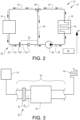
- Fig. 2 is a schematic side view of an internal combustion engine cooling system 12 comprising a radiator 14 and a coolant passage 16 adapted to cool at least a portion of an internal combustion engine 18.
- the internal combustion engine cooling system 12 and the internal combustion engine 18 may form an internal combustion engine assembly 13.
- the coolant passage 16 may comprise one or more conduits in an engine block (not shown) of the internal combustion engine 18 and/or one or more conduits external to the internal combustion engine 18 and arranged to be in thermal communication therewith.
- Fig. 2 illustrates that the internal combustion engine cooling system 12 has an extension in a vertical direction V and that the assembly 12 comprises a coolant feeding conduit assembly 20 for guiding coolant from the radiator 14 to the coolant passage 16, and a fluid returning conduit assembly 22 for guiding coolant from the coolant passage 16 to the radiator 14.
- the lowest point of the coolant feeding conduit assembly 20 may be lower than the highest point of the fluid returning conduit assembly 22.
- Fig. 2 illustrates a cooling system valve 24 adapted to be located between the radiator 14 and the coolant passage 16, as seen in an intended direction of flow from the radiator 14 to the coolant passage 16.
- the cooling system valve 24 may be located in the coolant feeding conduit assembly 20.
- the intended direction of flow may for instance be achieved by a pump 26.
- the pump may be located between the radiator 14 to the coolant passage 16, such as in the Fig. 2 coolant feeding conduit assembly 20.
- the portion of the internal combustion engine cooling system 12 connecting the radiator 14 to the coolant passage 16 generally is the lowermost portion of the assembly 12.
- the cooling system valve 24 may be located between the radiator 14 and the coolant pump 26.
- the Fig. 2 embodiment also comprises a thermostat valve 28 located between the coolant passage 16 and the radiator 14, as seen in an intended direction of flow from the coolant passage 16 to the radiator 14.
- the thermostat valve 28 may be located in the Fig. 2 fluid returning conduit assembly 22.
- the purpose of the thermostat valve 28 is to bypass the radiator 14 under certain conditions, for instance if the coolant temperature is lower than a predetermined threshold temperature.
- the thermostat valve 28 may be in fluid communication with a bypass conduit 30 and the thermostat valve 28 may be arranged to selectively provide a fluid communication between a portion of the fluid returning conduit assembly 22 and the bypass conduit 30.
- the cooling system valve 24 is distinct from the thermostat valve 28.
- thermostat valve 28 may be omitted.
- the internal combustion engine cooling system 12 may also comprise a coupling 32 connecting a first feeding conduit assembly portion 20' to a second feeding conduit assembly portion 20".
- the coupling 32 is located between the radiator 14 and the cooling system valve 24, as seen in an intended direction of flow from the radiator 14 to the coolant passage 16.
- the coupling 32 may assume a disconnected condition, in which the first feeding conduit assembly portion 20' is fluidly disconnected from the second feeding conduit assembly portion 20", and a connected condition, in which the a first feeding conduit assembly portion 20' is fluidly connected to the second feeding conduit assembly portion 20".
- the second feeding conduit assembly portion 20" and the cooling system valve 24 may form part of a coolant conduit 34.
- the cooling system valve 24 is adapted to automatically assume each one of at least the following conditions:
- the ability to assume any one of the above conditions is beneficial in a least the following situations.
- the cooling system valve 24 may assume an open condition, thus allowing coolant to flow from the radiator 14 to the coolant passage 16 to thereby enable the internal combustion engine 18 to be appropriately cooled.
- certain service operations may require that the coupling 32 assumes a disconnected condition, thereby disconnecting the first feeding conduit assembly portion 20' from the second feeding conduit assembly portion 20".
- Examples of service operations requiring that the coupling 32 assumes a disconnected condition include for instance replacing or removing at least one of the following components of an internal combustion engine cooling system: the radiator 14, a fan shroud (not shown), a fan ring (not shown), an expansion tank (not shown) and the fluid returning conduit assembly 22.
- the cooling system valve 24 automatically assumes each one of at least the closed condition and the open condition. As such, an operator, such as a mechanic, need not actuate the cooling system valve 24 separately, e.g. prior to actuating the coupling 32, so as to assume its disconnected condition.
- the cooling system valve 24 is illustrated as a non-return valve in the Fig. 2 embodiment. However, as will be elaborated on hereinabove, a plurality of various embodiments of the cooling system valve 24 is envisioned.
- the cooling system valve 24 may be adapted to automatically assume each one of the conditions, i.e. open or closed, in dependence of an operational state of the internal combustion engine 18.
- the cooling system valve 24 may be adapted to receive one or more signals from the internal combustion engine 18 or a control unit 36, such as an electronic control unit, controlling the operation of the internal combustion engine 18.
- control signals may be electric, hydraulic, pneumatic or mechanical control signals or any combination thereof.
- the cooling system valve 24 may be adapted to assume a condition in response to the signal or signals received.
- the operational state may comprise at least one of the following: a coolant temperature, a coolant flow rate, a coolant pressure and an indication whether or not the internal combustion engine is running.
- the cooling system valve 24 may be adapted to automatically assume each one of the conditions in dependence of a pressure applied to at least a portion of the cooling system valve 24.
- the cooling system valve 24 is adapted to automatically assume each one of the conditions in dependence of a pressure P u upstream the cooling system valve 24, as seen in an intended direction of flow from the radiator 14 to the coolant passage 16.
- the feeding conduit assembly 20 when the coupling 32 assumes its connected condition, the feeding conduit assembly 20 generally is filled with coolant, resulting in that the pressure P u upstream the cooling system valve 24 corresponds to the liquid column of the coolant located directly upstream the cooling system valve 24.
- the portion of the feeding conduit assembly 20 located between the coupling 32 and the cooling system valve 24, i.e. the second feeding conduit assembly portion 20 is exposed to the environment ambient of the coolant feeding conduit assembly 20.
- the portion of the feeding conduit assembly 20 located between the coupling 32 and the cooling system valve 24 is filled with air.
- the pressure P u upstream the cooling system valve 24 generally is lower than when the coupling 32 assumes its connected condition and such a pressure difference may be used for controlling the condition of the cooling system valve 24.
- the cooling system valve 24 may be adapted to automatically assume the closed condition when the pressure P u upstream the cooling system valve 24 is equal to or below a predetermined threshold value.
- Fig. 4a to Fig. 6b illustrate embodiments of the cooling system valve 24, the conditions of which are controllable by the pressure P u upstream the cooling system valve 24.
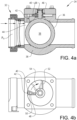
- the Fig. 4a to Fig. 6b embodiments have a plurality of features in common and the common features will be presented with reference to the Fig. 4a and Fig. 4b embodiment.
- the Fig. 4a and Fig. 4b embodiment comprises a valve member 36 and a valve housing 38 wherein the valve member 36 is moveable relative to the valve housing 38 to thereby obtain the open and closed conditions.
- the position of the valve member 36 relative to the valve housing 38 is controlled by the pressure P u upstream the cooling system valve 24.
- the valve member 36 is adapted to pivot relative the valve housing 38.
- the cooling system valve 24 comprises a valve member actuator 40, adapted to move the valve member 36 relative to the valve housing 38.
- the valve member actuator 40 is fixedly connected to the valve member 36 and the valve member actuator 40 is adapted to pivot in response to a pressure on the actuator chamber 48.
- the valve member 36 may comprise a fluid passage 56, such as an opening, extending through the valve member 36.
- the fluid passage 56 may be located and oriented such that fluid may flow through the fluid passage 56 when the cooling system valve 24 assumes the open condition whereas fluid cannot flow through the fluid passage 56 when the cooling system valve 24 assumes the closed condition.
- the valve member 36 may be substantially spherically shaped and the fluid passage 56 may extend therethrough such that when the cooling system valve 24 assumes the open condition, the fluid passage 56 is oriented with its main extension substantially parallel to the intended direction of flow through the cooling system valve 24 and when the cooling system valve 24 assumes the closed condition, the fluid passage 56 is oriented with its main extension substantially perpendicular to the intended direction of flow through the cooling system valve 24.
- Fig. 4a illustrates the cooling system valve 24 in the closed position.
- the Fig. 4a cooling system valve 24 further comprises a pilot pressure conduit 42 in fluid communication with the valve member actuator 40.
- the pilot pressure conduit 42 is adapted to be in fluid communication with a portion 44 of the cooling system valve upstream the valve member 36, as seen in an intended direction of flow from the radiator to the coolant passage (not shown in Fig. 4a ).
- the pilot pressure conduit may be in fluid communication with another fluid source, such as a pilot pressure fluid source (not shown), external of the coolant feeding conduit assembly 20, which pilot pressure fluid source feeds fluid at a pilot pressure to the valve member actuator 40.
- Fig. 4a illustrates that the cooling system valve 24 illustrated therein comprises a lid 46 such that the valve member actuator 40 is located between the valve member 36 and the lid 46.
- Fig. 4b is a top view of the Fig. 4a but in Fig. 4b , the lid 46 has been removed.
- the cooling system valve 24 comprises the actuator chamber 48 in fluid communication with the pilot pressure conduit 42.
- the actuator chamber 48 may be a cavity in the valve housing 38.
- the actuator chamber 48 may be drilled, milled or cut into the valve housing material, such that the actuator chamber 48 is confined by end surfaces 50, 52 of the valve housing 38.
- valve member actuator 40 delimits the actuator chamber 48 such that the valve member actuator 40 can move in response to a pressure in the actuator chamber 48.
- the Fig. 4b valve member actuator 40 will rotate in a clockwise direction, as indicated by arrow 54 in Fig. 4b , as a consequence of which the valve member 36 will also rotate.
- the valve member actuator 40 and the valve member 36 will move in concert such that the cooling system valve 24 assumes the open condition.
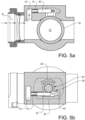
- FIG. 5a and 5b Another embodiment of the cooling system valve 24 is illustrated in Fig. 5a and 5b .
- Fig. 5a and Fig. 5b features that are similar to the features of the Fig. 4a and Fig. 4b embodiment are assigned the same reference numerals, but the features or their intended functions are repeated in the below presentation of the Fig. 5a and Fig. 5b embodiment.
- the valve member actuator 40 illustrated therein is connected to the valve member 36 via a transmission arrangement 58 transferring a rectilinear motion of the valve member actuator 40 into a pivot motion of the valve member 36.
- the transmission arrangement 58 is exemplified as a pinion 60, for instance fixedly connected to the valve member 36, and a rack 62, for instance fixedly connected to or forming part of the valve member actuator 40.
- the cooling system valve 24 may comprise a biasing means adapted to bias the valve member 36 towards the closed condition.
- the biasing means may be such that when the pressure in the pilot pressure conduit 42 is below a predetermined pressure threshold level, the biasing means can move the valve member 36 such that the cooling system valve 24 assumes its closed condition.
- the biasing means is implemented as a torsion spring 68.
- the Fig. 4a biasing means may connect the valve housing 38 to the valve member 36.
- the biasing means is implemented as a tension spring 70, such as a coil spring, connecting the valve housing 38 to the rack 62.
- the Fig. 5a and Fig. 5b embodiment may comprise a compression spring (not shown) between the rack 62 and the valve housing 38, such a compression spring may for instance be located to the right of the rack 62 in Fig. 5b .
- FIG. 6a and 6b Another embodiment of the cooling system valve 24 is illustrated in Fig. 6a and 6b .
- Fig. 6a and Fig. 6b features that are similar to the features of the Fig. 4a and Fig. 4b embodiment are assigned the same reference numerals, but the features or their intended functions are repeated in the below presentation of the Fig. 6a and Fig. 6b embodiment.
- valve member actuator 40 is adapted to accommodate fluid fed from the pilot pressure conduit 42. Moreover, the valve member actuator 40 is adapted to deform in response to a pressure of the fluid accommodated in the valve member actuator 40.
- the Fig. 6a and Fig. 6b valve member actuator 40 may for instance comprise a flexible conduit with a radial inner portion 72 fixedly connected to the valve member 36 and a radial outer portion 74 fixedly connected to the valve housing 38.
- the valve member actuator 40 may have a coiled shape around the rotational centre of the valve member 36 such that when the pressure in the valve member actuator 40 is above a predetermined threshold pressure, the valve member actuator 40 unwinds and thereby rotates the valve member 36.
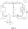
- the above-discussed coolant conduit 34 comprising a cooling system valve 24, may be used in a method for assembling a combustion engine cooling system 12, such as the Fig. 2 cooling system 12.
- the method comprises connecting the radiator 14 to the coolant passage 16 by means of the coolant conduit 34.
- the above method may be used for constructing a new cooling system 12.
- the above method may also form a part of a procedure for modifying a cooling system 12.
- Fig. 7 illustrating an existing cooling system 12, having a coolant transport conduit 76, forming a part of the first feeding conduit assembly portion 20' and being located between the radiator 14 and the pump 26.
- Such an existing cooling system 12 may be modified by replacing the coolant transport conduit 76 by a coolant conduit 34 according to the present invention.
- the coolant conduit 34 may comprise a coupling 32, or at least a portion of such a coupling, in order to enable that the coolant conduit 34 forms part of the first feeding conduit assembly portion 20' in a time-efficient manner. It is envisioned that embodiments of the coolant conduit 34 may be constituted by the cooling system valve 24 and the coupling 32.
- An internal combustion engine cooling system 12 may be used in a method for fluidly disconnecting a radiator 14 from a coolant passage 16 adapted to cool at least a portion of an internal combustion engine 18.
- the radiator 14 is fluidly connected to the coolant passage 16 by means of a coolant conduit 34, as discussed hereinabove.
- the method comprises disconnecting the coolant conduit 34 from the radiator 14 whereby the cooling system valve 24 of the coolant conduit 34 closes automatically.
- the above method may preferably be used in a method for performing service on an internal combustion engine cooling system 12 in accordance with the present invention.
- the method comprises fluidly disconnecting the radiator from the coolant passage in accordance with the seventh aspect of the present invention.
Landscapes
- Engineering & Computer Science (AREA)
- General Engineering & Computer Science (AREA)
- Mechanical Engineering (AREA)
- Chemical & Material Sciences (AREA)
- Combustion & Propulsion (AREA)
- Cooling, Air Intake And Gas Exhaust, And Fuel Tank Arrangements In Propulsion Units (AREA)
- Temperature-Responsive Valves (AREA)
Claims (18)
- Kühlsystemventil (24) für ein Verbrennungsmotorkühlsystem (12), das Verbrennungsmotorkühlsystem (12) umfassend einen Kühler (14) und einen Kühlmitteldurchgang (16), der angepasst ist, um mindestens einen Abschnitt eines Verbrennungsmotors (18) zu kühlen, wobei das Kühlsystemventil (24) angepasst ist, um sich zwischen dem Kühler (14) und dem Kühlmitteldurchgang (16) zu befinden, wie in einer beabsichtigten Strömungsrichtung von dem Kühler (14) zu dem Kühlmitteldurchgang (16) gesehen, wobei das Kühlsystemventil (24) angepasst ist, um jede von mindestens den folgenden Zuständen automatisch einzunehmen:- einen offenen Zustand, der einen Kühlmitteltransport von dem Kühler (14) zu dem Kühlmitteldurchgang (16) hin über das Kühlsystemventil (24) ermöglicht, und- einen geschlossenen Zustand, der den Kühlmitteltransport in einer Richtung von dem Kühlmitteldurchgang (16) zu dem Kühler (14) hin über das Kühlsystemventil (24) verhindert,wobei das Kühlsystemventil (24) angepasst ist, um jeden der Zustände in Abhängigkeit eines Drucks stromaufwärts des Kühlsystemventils (24) einzunehmen, wie in einer beabsichtigten Strömungsrichtung von dem Kühler (14) zu dem Kühlmitteldurchlass (16) gesehen, wobei das Kühlsystemventil (24) ein Ventilelement (36) und ein Ventilgehäuse (38) umfasst, wobei das Ventilelement (36) relativ zu dem Ventilgehäuse (38) bewegbar ist, wobei dadurch die offenen und geschlossenen Zustände erhalten werden, wobei die Position des Ventilelements (36) relativ zu dem Ventilgehäuse (38) durch den Druck stromaufwärts des Kühlsystemventils (24) gesteuert wird, wobei das Ventilelement (36) angepasst ist, um relativ zu dem Ventilgehäuse (38) zu schwenken, dadurch gekennzeichnet, dass das Kühlsystemventil (24) einen druckbetätigten Ventilelementaktuator (40) umfasst, der angepasst ist, um das Ventilelement (36) relativ zu dem Ventilgehäuse (38) unter Wirkung des Fluiddrucks stromaufwärts des Kühlsystemventils zu bewegen, das Kühlsystemventil (24) ferner umfassend eine Steuerdruckleitung (42) in Fluidkommunikation mit dem Ventilelementaktuator (40).
- Kühlsystemventil (24) nach Anspruch 1, wobei das Kühlsystemventil (24) angepasst ist, um den geschlossenen Zustand automatisch einzunehmen, wenn der Druck stromaufwärts des Kühlsystemventils (24) gleich oder unterhalb eines zuvor bestimmten Schwellenwerts ist.
- Kühlsystemventil (24) nach einem der vorstehenden Ansprüche,
wobei die Steuerdruckleitung (42) den Ventilelementaktuator (40) mit einem Abschnitt des Kühlsystemventils (24) stromaufwärts des Ventilelements (36) fluidisch verbindet, wie in einer beabsichtigten Strömungsrichtung von dem Kühler (14) zu dem Kühlmitteldurchgang (16) gesehen. - Kühlsystemventil (24) nach einem der vorstehenden Ansprüche,
wobei das Kühlsystemventil (24) eine Aktuatorkammer (48) in Fluidkommunikation mit der Steuerdruckleitung (42) umfasst, wobei mindestens ein Abschnitt des Ventilelementaktuators (40) die Aktuatorkammer (48) derart begrenzt, dass sich der Ventilelementaktuator (40) als Reaktion auf einen Druck in der Aktuatorkammer (48) bewegen kann. - Kühlsystemventil (24) nach Anspruch 4,
wobei der Ventilelementaktuator (40) mit dem Ventilelement (36) fest verbunden ist, wobei der Ventilelementaktuator (40) angepasst ist, um als Reaktion auf einen Druck in der Aktuatorkammer (48) zu schwenken. - Kühlsystemventil (24) nach Anspruch 4 oder 5,
wobei der Ventilelementaktuator (40) über eine Übertragungsanordnung (58) mit dem Ventilelement (36) verbunden ist, die eine geradlinige Bewegung des Ventilelementaktuators (40) in eine Schwenkbewegung des Ventilelements (36) weiterleitet, wobei der Ventilelementaktuator (40) angepasst ist, um sich als Reaktion auf einen Druck in der Aktuatorkammer (48) geradlinig zu bewegen. - Kühlsystemventil (24) nach einem der vorstehenden Ansprüche,
wobei der Ventilelementaktuator (40) angepasst ist, um Fluid aufzunehmen, das von der Steuerdruckleitung (42) zugeführt wird, wobei der Ventilelementaktuator (40) angepasst ist, um sich als Reaktion auf einen Druck des Fluids zu verformen, das in dem Ventilelementaktuator (40) aufgenommen wird. - Kühlsystemventil (24) nach Anspruch 7, wobei der Ventilelementaktuator (40) mit dem Ventilelement (36) fest verbunden ist.
- Kühlsystemventil (24) nach einem der vorstehenden Ansprüche,
wobei das Kühlsystemventil (24) ein Vorspannmittel umfasst, das angepasst ist, um das Ventilelement (36) zu dem geschlossenen Zustand hin vorzuspannen. - Kühlmittelleitung (34), die angepasst ist, um einen Teil eines Verbrennungsmotorkühlsystems (12) auszubilden, umfassend einen Kühler (14) und einen Kühlmitteldurchgang (16), der angepasst ist, um mindestens einen Abschnitt eines Verbrennungsmotors (18) zu kühlen, wobei die Kühlmittelleitung (34) angepasst ist, um sich zwischen dem Kühler (14) und dem Kühlmitteldurchgang (16) zu befinden, wie in einer beabsichtigten Strömungsrichtung von dem Kühler (14) zu dem Kühlmitteldurchgang (16) gesehen, die Kühlmittelleitung (34) umfassend ein Kühlsystemventil (24) nach einem der vorstehenden Ansprüche.
- Verbrennungsmotorkühlsystem (12), umfassend einen Kühler (14) und einen Kühlmitteldurchgang (16), der angepasst ist, um mindestens einen Abschnitt eines Verbrennungsmotors (18) zu kühlen, das Verbrennungsmotorkühlsystem (12) umfassend ein Kühlsystemventil (24) nach einem der Ansprüche 1 bis 9 und/oder eine Kühlmittelleitung (34) nach Anspruch 10, wobei sich das Kühlsystemventil (24) zwischen dem Kühler (14) und dem Kühlmitteldurchgang (16) befindet, wie in einer beabsichtigten Strömungsrichtung von dem Kühler (14) zu dem Kühlmitteldurchgang (16) gesehen.
- Verbrennungsmotorkühlsystem (12) nach Anspruch 11,
wobei das Verbrennungsmotorkühlsystem (12) ferner eine Kühlmittelpumpe umfasst, die angepasst ist, um Kühlmittel in dem Verbrennungsmotorkühlsystem (12) zu zirkulieren, wobei sich die Kühlmittelpumpe zwischen dem Kühler (14) und dem Kühlmitteldurchgang (16) befindet, wie in einer beabsichtigten Strömungsrichtung von dem Kühler (14) zu dem Kühlmitteldurchgang (16) gesehen. - Verbrennungsmotorkühlsystem (12) nach Anspruch 12,
wobei sich das Kühlsystemventil (24) zwischen dem Kühler (14) und der Kühlmittelpumpe befindet, wie in einer beabsichtigten Strömungsrichtung von dem Kühler (14) zu dem Kühlmitteldurchgang (16) gesehen. - Verbrennungsmotoranordnung (13), umfassend einen Verbrennungsmotor (18) und ein Verbrennungsmotorkühlsystem (12) nach einem der Ansprüche 11 bis 13.
- Fahrzeug, umfassend eine Verbrennungsmotoranordnung (13) nach Anspruch 14.
- Verfahren zum Montieren eines Verbrennungsmotorkühlsystems (12), das Verbrennungsmotorkühlsystem umfassend einen Kühler (14) und einen Kühlmitteldurchgang (16), der angepasst ist, um mindestens einen Abschnitt eines Verbrennungsmotors (18) zu kühlen, das Verfahren umfassend das Verbinden des Kühlers (14) mit dem Kühlmitteldurchgang (16) mittels einer Kühlmittelleitung (34) nach Anspruch 10.
- Verfahren zum fluidischen Trennen eines Kühlers (14) von einem Kühlmitteldurchgang (16), der angepasst ist, um mindestens einen Abschnitt eines Verbrennungsmotorkühlsystems (12) zu kühlen, wobei, während Betriebszuständen des Verbrennungsmotorkühlsystems (12), der Kühler (14) mit dem Kühlmitteldurchgang (16) mittels einer Kühlmittelleitung (34) nach Anspruch 10 fluidisch verbunden ist, das Verfahren umfassend das Trennen der Kühlmittelleitung (34) von dem Kühler (14), wodurch das Kühlsystemventil (24) automatisch schließt.
- Verfahren zum Durchführen eines Dienstes an einem Verbrennungsmotorkühlsystem (12), umfassend einen Kühler (14), einen Kühlmitteldurchgang (16), der angepasst ist, um mindestens einen Abschnitt eines Verbrennungsmotors (18) und eine Kühlmittelleitung (34) zu kühlen, das Verfahren umfassend ein fluidisches Trennen des Kühlers (14) von dem Kühlmitteldurchgang (16) gemäß Anspruch 17.
Applications Claiming Priority (2)
| Application Number | Priority Date | Filing Date | Title |
|---|---|---|---|
| IN201641042177 | 2016-12-09 | ||
| PCT/EP2017/080627 WO2018104106A1 (en) | 2016-12-09 | 2017-11-28 | A cooling system valve |
Publications (3)
| Publication Number | Publication Date |
|---|---|
| EP3551863A1 EP3551863A1 (de) | 2019-10-16 |
| EP3551863C0 EP3551863C0 (de) | 2024-05-01 |
| EP3551863B1 true EP3551863B1 (de) | 2024-05-01 |
Family
ID=60788541
Family Applications (1)
| Application Number | Title | Priority Date | Filing Date |
|---|---|---|---|
| EP17818434.7A Active EP3551863B1 (de) | 2016-12-09 | 2017-11-28 | Kühlsystemventil |
Country Status (4)
| Country | Link |
|---|---|
| US (1) | US11053837B2 (de) |
| EP (1) | EP3551863B1 (de) |
| CN (1) | CN110050114B (de) |
| WO (1) | WO2018104106A1 (de) |
Family Cites Families (21)
| Publication number | Priority date | Publication date | Assignee | Title |
|---|---|---|---|---|
| US1285267A (en) | 1918-05-28 | 1918-11-19 | Edward Kingstone Lund | Internal-combustion engine. |
| GB160994A (en) | 1920-01-21 | 1921-04-07 | Charlie Bird | An improved radiator for motor cars and the like |
| US2998223A (en) * | 1958-11-20 | 1961-08-29 | Baxter Filtration Corp | Valve assembly |
| DE1576703A1 (de) * | 1967-08-09 | 1970-04-23 | Buessing Automobilwerke Ag | Wassergekuehlte Brennkraftmaschine |
| US3774678A (en) | 1971-04-07 | 1973-11-27 | F Glorisi | Cooling system with selectively replaceable radiator sections |
| CH596485A5 (de) * | 1975-08-20 | 1978-03-15 | Sulzer Ag | |
| US4546792A (en) * | 1982-04-28 | 1985-10-15 | Lew Hyok S | Ball-plug pendulum check valve |
| JPH0768897B2 (ja) * | 1988-04-04 | 1995-07-26 | マツダ株式会社 | エンジンの冷却装置 |
| US5404842A (en) * | 1992-12-15 | 1995-04-11 | Nippon Soken, Inc. | Internal combustion engine cooling apparatus |
| IT1291190B1 (it) * | 1997-03-13 | 1998-12-29 | Gate Spa | Sistema di raffreddamento per un motore a combustione interna, particolarmente per autoveicoli |
| DE19741861B4 (de) * | 1997-09-23 | 2004-07-22 | Daimlerchrysler Ag | Vorrichtung zur Regelung des Kühlwasserkreislaufes für einen Verbrennungsmotor |
| DE60102289T2 (de) * | 2001-03-29 | 2005-03-24 | Komatsu Utility Europe S.P.A., Noventa Vicentina | Radiator für eine Erdbewegungsmaschine |
| US6637472B2 (en) * | 2001-05-08 | 2003-10-28 | Moc Products Company, Inc. | Coolant transfer machine for automotive vehicle & method |
| GB0121504D0 (en) | 2001-09-05 | 2001-10-24 | Lovatt Edward | Improvements in and relating to fluid flow control apparatus |
| US8881693B2 (en) * | 2011-03-18 | 2014-11-11 | Toyota Jidosha Kabushiki Kaisha | Cooling system of engine |
| JP5919031B2 (ja) * | 2012-02-28 | 2016-05-18 | 株式会社ミクニ | 冷却水制御バルブ装置 |
| CN104541032B (zh) * | 2013-06-17 | 2017-03-08 | 丰田自动车株式会社 | 内燃机系统的冷却装置及其控制方法 |
| DE102014212324A1 (de) * | 2014-06-26 | 2015-12-31 | Robert Bosch Gmbh | Ventileinrichtung |
| JP6319019B2 (ja) * | 2014-09-25 | 2018-05-09 | アイシン精機株式会社 | 流体制御装置 |
| FR3036135A1 (fr) * | 2015-05-13 | 2016-11-18 | Peugeot Citroen Automobiles Sa | Circuit de refroidissement d’un moteur |
| JP6461221B2 (ja) * | 2017-03-30 | 2019-01-30 | 株式会社Subaru | エンジンの制御装置 |
-
2017
- 2017-11-28 EP EP17818434.7A patent/EP3551863B1/de active Active
- 2017-11-28 CN CN201780075953.6A patent/CN110050114B/zh active Active
- 2017-11-28 US US16/467,657 patent/US11053837B2/en active Active
- 2017-11-28 WO PCT/EP2017/080627 patent/WO2018104106A1/en not_active Ceased
Also Published As
| Publication number | Publication date |
|---|---|
| EP3551863A1 (de) | 2019-10-16 |
| WO2018104106A1 (en) | 2018-06-14 |
| EP3551863C0 (de) | 2024-05-01 |
| CN110050114B (zh) | 2021-04-09 |
| US11053837B2 (en) | 2021-07-06 |
| CN110050114A (zh) | 2019-07-23 |
| US20200072116A1 (en) | 2020-03-05 |
Similar Documents
| Publication | Publication Date | Title |
|---|---|---|
| US9248854B2 (en) | Electro-hydraulic steering control system | |
| CA2864480C (en) | Valve with integrated wax motor bypass fail safe | |
| US9290252B1 (en) | Systems and methods for controlling trim position of a marine propulsion device on a marine vessel | |
| JPH11152090A (ja) | 船舶推進機用チルト装置 | |
| JP2012176698A (ja) | 船舶推進機用トリム・チルト装置 | |
| EP3458727B1 (de) | Elektrohydraulisches antriebs- und steuerungssystem | |
| US7131386B1 (en) | Marine propulsion system with pressure compensated hydraulic supply capability | |
| US7267588B1 (en) | Selectively lockable marine propulsion devices | |
| EP3551863B1 (de) | Kühlsystemventil | |
| US20130000761A1 (en) | Transmission fluid expansion reservoir | |
| CN101370702B (zh) | 用于车辆的车架转向的控制系统以及用于控制车架转向式车辆中的两个转向液压缸的方法 | |
| US20020098747A1 (en) | Watercraft hydraulic apparatus | |
| US6042434A (en) | Hydraulic tilt and trim unit for marine drive | |
| CN214698618U (zh) | 一种集成式泵控闭式拨叉电动液压舵机 | |
| EP3596353B1 (de) | Verfahren zum trennen einer ventileinheit von einer pneumatisch gesteuerten stellgliedanordnung | |
| EP3726090B1 (de) | Pneumatisch gesteuerte stelleranordnung | |
| JP2001030992A (ja) | 船舶推進機用トリム・チルト装置 | |
| CN110050113B (zh) | 具有提供三个风扇电动机操作位置的电动液压阀的风扇控制系统 | |
| US11279200B2 (en) | Motor vehicle wheelset anti-roll device with actuating means operated by a hydraulic control circuit | |
| CN117184393A (zh) | 一种具备失电应急功能的电液操舵装置及方法 | |
| US11084516B2 (en) | Hydraulic helm pump with integrated electric pump | |
| US11002176B2 (en) | Temperature regulator with a unitary housing, thermostatic valves and valve holders | |
| WO2007050550A1 (en) | Cooling system for a work machine | |
| CN112709729A (zh) | 一种集成式泵控闭式拨叉电动液压舵机 | |
| JP2001030994A (ja) | 船舶推進機用トリム・チルト装置 |
Legal Events
| Date | Code | Title | Description |
|---|---|---|---|
| STAA | Information on the status of an ep patent application or granted ep patent |
Free format text: STATUS: UNKNOWN |
|
| STAA | Information on the status of an ep patent application or granted ep patent |
Free format text: STATUS: THE INTERNATIONAL PUBLICATION HAS BEEN MADE |
|
| PUAI | Public reference made under article 153(3) epc to a published international application that has entered the european phase |
Free format text: ORIGINAL CODE: 0009012 |
|
| STAA | Information on the status of an ep patent application or granted ep patent |
Free format text: STATUS: REQUEST FOR EXAMINATION WAS MADE |
|
| 17P | Request for examination filed |
Effective date: 20190704 |
|
| AK | Designated contracting states |
Kind code of ref document: A1 Designated state(s): AL AT BE BG CH CY CZ DE DK EE ES FI FR GB GR HR HU IE IS IT LI LT LU LV MC MK MT NL NO PL PT RO RS SE SI SK SM TR |
|
| AX | Request for extension of the european patent |
Extension state: BA ME |
|
| DAV | Request for validation of the european patent (deleted) | ||
| DAX | Request for extension of the european patent (deleted) | ||
| STAA | Information on the status of an ep patent application or granted ep patent |
Free format text: STATUS: EXAMINATION IS IN PROGRESS |
|
| 17Q | First examination report despatched |
Effective date: 20210805 |
|
| GRAP | Despatch of communication of intention to grant a patent |
Free format text: ORIGINAL CODE: EPIDOSNIGR1 |
|
| STAA | Information on the status of an ep patent application or granted ep patent |
Free format text: STATUS: GRANT OF PATENT IS INTENDED |
|
| RIC1 | Information provided on ipc code assigned before grant |
Ipc: F16K 31/363 20060101ALI20231107BHEP Ipc: F16K 31/36 20060101ALI20231107BHEP Ipc: F16K 31/163 20060101ALI20231107BHEP Ipc: F16K 17/34 20060101ALI20231107BHEP Ipc: F01P 11/02 20060101ALI20231107BHEP Ipc: F01P 7/14 20060101ALI20231107BHEP Ipc: F16K 5/06 20060101ALI20231107BHEP Ipc: F16K 15/18 20060101ALI20231107BHEP Ipc: F16K 15/03 20060101ALI20231107BHEP Ipc: F01P 11/04 20060101AFI20231107BHEP |
|
| INTG | Intention to grant announced |
Effective date: 20231213 |
|
| GRAS | Grant fee paid |
Free format text: ORIGINAL CODE: EPIDOSNIGR3 |
|
| GRAA | (expected) grant |
Free format text: ORIGINAL CODE: 0009210 |
|
| STAA | Information on the status of an ep patent application or granted ep patent |
Free format text: STATUS: THE PATENT HAS BEEN GRANTED |
|
| AK | Designated contracting states |
Kind code of ref document: B1 Designated state(s): AL AT BE BG CH CY CZ DE DK EE ES FI FR GB GR HR HU IE IS IT LI LT LU LV MC MK MT NL NO PL PT RO RS SE SI SK SM TR |
|
| REG | Reference to a national code |
Ref country code: GB Ref legal event code: FG4D |
|
| REG | Reference to a national code |
Ref country code: CH Ref legal event code: EP |
|
| REG | Reference to a national code |
Ref country code: DE Ref legal event code: R096 Ref document number: 602017081617 Country of ref document: DE |
|
| REG | Reference to a national code |
Ref country code: IE Ref legal event code: FG4D |
|
| U01 | Request for unitary effect filed |
Effective date: 20240528 |
|
| U07 | Unitary effect registered |
Designated state(s): AT BE BG DE DK EE FI FR IT LT LU LV MT NL PT SE SI Effective date: 20240606 |
|
| PG25 | Lapsed in a contracting state [announced via postgrant information from national office to epo] |
Ref country code: IS Free format text: LAPSE BECAUSE OF FAILURE TO SUBMIT A TRANSLATION OF THE DESCRIPTION OR TO PAY THE FEE WITHIN THE PRESCRIBED TIME-LIMIT Effective date: 20240901 |
|
| PG25 | Lapsed in a contracting state [announced via postgrant information from national office to epo] |
Ref country code: HR Free format text: LAPSE BECAUSE OF FAILURE TO SUBMIT A TRANSLATION OF THE DESCRIPTION OR TO PAY THE FEE WITHIN THE PRESCRIBED TIME-LIMIT Effective date: 20240501 |
|
| PG25 | Lapsed in a contracting state [announced via postgrant information from national office to epo] |
Ref country code: GR Free format text: LAPSE BECAUSE OF FAILURE TO SUBMIT A TRANSLATION OF THE DESCRIPTION OR TO PAY THE FEE WITHIN THE PRESCRIBED TIME-LIMIT Effective date: 20240802 |
|
| PG25 | Lapsed in a contracting state [announced via postgrant information from national office to epo] |
Ref country code: ES Free format text: LAPSE BECAUSE OF FAILURE TO SUBMIT A TRANSLATION OF THE DESCRIPTION OR TO PAY THE FEE WITHIN THE PRESCRIBED TIME-LIMIT Effective date: 20240501 |
|
| PG25 | Lapsed in a contracting state [announced via postgrant information from national office to epo] |
Ref country code: PL Free format text: LAPSE BECAUSE OF FAILURE TO SUBMIT A TRANSLATION OF THE DESCRIPTION OR TO PAY THE FEE WITHIN THE PRESCRIBED TIME-LIMIT Effective date: 20240501 |
|
| PG25 | Lapsed in a contracting state [announced via postgrant information from national office to epo] |
Ref country code: PL Free format text: LAPSE BECAUSE OF FAILURE TO SUBMIT A TRANSLATION OF THE DESCRIPTION OR TO PAY THE FEE WITHIN THE PRESCRIBED TIME-LIMIT Effective date: 20240501 Ref country code: NO Free format text: LAPSE BECAUSE OF FAILURE TO SUBMIT A TRANSLATION OF THE DESCRIPTION OR TO PAY THE FEE WITHIN THE PRESCRIBED TIME-LIMIT Effective date: 20240801 Ref country code: IS Free format text: LAPSE BECAUSE OF FAILURE TO SUBMIT A TRANSLATION OF THE DESCRIPTION OR TO PAY THE FEE WITHIN THE PRESCRIBED TIME-LIMIT Effective date: 20240901 Ref country code: HR Free format text: LAPSE BECAUSE OF FAILURE TO SUBMIT A TRANSLATION OF THE DESCRIPTION OR TO PAY THE FEE WITHIN THE PRESCRIBED TIME-LIMIT Effective date: 20240501 Ref country code: GR Free format text: LAPSE BECAUSE OF FAILURE TO SUBMIT A TRANSLATION OF THE DESCRIPTION OR TO PAY THE FEE WITHIN THE PRESCRIBED TIME-LIMIT Effective date: 20240802 Ref country code: ES Free format text: LAPSE BECAUSE OF FAILURE TO SUBMIT A TRANSLATION OF THE DESCRIPTION OR TO PAY THE FEE WITHIN THE PRESCRIBED TIME-LIMIT Effective date: 20240501 Ref country code: RS Free format text: LAPSE BECAUSE OF FAILURE TO SUBMIT A TRANSLATION OF THE DESCRIPTION OR TO PAY THE FEE WITHIN THE PRESCRIBED TIME-LIMIT Effective date: 20240801 |
|
| U20 | Renewal fee for the european patent with unitary effect paid |
Year of fee payment: 8 Effective date: 20241127 |
|
| PG25 | Lapsed in a contracting state [announced via postgrant information from national office to epo] |
Ref country code: CZ Free format text: LAPSE BECAUSE OF FAILURE TO SUBMIT A TRANSLATION OF THE DESCRIPTION OR TO PAY THE FEE WITHIN THE PRESCRIBED TIME-LIMIT Effective date: 20240501 |
|
| PG25 | Lapsed in a contracting state [announced via postgrant information from national office to epo] |
Ref country code: RO Free format text: LAPSE BECAUSE OF FAILURE TO SUBMIT A TRANSLATION OF THE DESCRIPTION OR TO PAY THE FEE WITHIN THE PRESCRIBED TIME-LIMIT Effective date: 20240501 Ref country code: SK Free format text: LAPSE BECAUSE OF FAILURE TO SUBMIT A TRANSLATION OF THE DESCRIPTION OR TO PAY THE FEE WITHIN THE PRESCRIBED TIME-LIMIT Effective date: 20240501 |
|
| PG25 | Lapsed in a contracting state [announced via postgrant information from national office to epo] |
Ref country code: SM Free format text: LAPSE BECAUSE OF FAILURE TO SUBMIT A TRANSLATION OF THE DESCRIPTION OR TO PAY THE FEE WITHIN THE PRESCRIBED TIME-LIMIT Effective date: 20240501 |
|
| PG25 | Lapsed in a contracting state [announced via postgrant information from national office to epo] |
Ref country code: SM Free format text: LAPSE BECAUSE OF FAILURE TO SUBMIT A TRANSLATION OF THE DESCRIPTION OR TO PAY THE FEE WITHIN THE PRESCRIBED TIME-LIMIT Effective date: 20240501 Ref country code: SK Free format text: LAPSE BECAUSE OF FAILURE TO SUBMIT A TRANSLATION OF THE DESCRIPTION OR TO PAY THE FEE WITHIN THE PRESCRIBED TIME-LIMIT Effective date: 20240501 Ref country code: RO Free format text: LAPSE BECAUSE OF FAILURE TO SUBMIT A TRANSLATION OF THE DESCRIPTION OR TO PAY THE FEE WITHIN THE PRESCRIBED TIME-LIMIT Effective date: 20240501 Ref country code: CZ Free format text: LAPSE BECAUSE OF FAILURE TO SUBMIT A TRANSLATION OF THE DESCRIPTION OR TO PAY THE FEE WITHIN THE PRESCRIBED TIME-LIMIT Effective date: 20240501 |
|
| REG | Reference to a national code |
Ref country code: DE Ref legal event code: R097 Ref document number: 602017081617 Country of ref document: DE |
|
| PLBE | No opposition filed within time limit |
Free format text: ORIGINAL CODE: 0009261 |
|
| STAA | Information on the status of an ep patent application or granted ep patent |
Free format text: STATUS: NO OPPOSITION FILED WITHIN TIME LIMIT |
|
| 26N | No opposition filed |
Effective date: 20250204 |
|
| REG | Reference to a national code |
Ref country code: CH Ref legal event code: PL |
|
| PG25 | Lapsed in a contracting state [announced via postgrant information from national office to epo] |
Ref country code: MC Free format text: LAPSE BECAUSE OF FAILURE TO SUBMIT A TRANSLATION OF THE DESCRIPTION OR TO PAY THE FEE WITHIN THE PRESCRIBED TIME-LIMIT Effective date: 20240501 |
|
| REG | Reference to a national code |
Ref country code: CH Ref legal event code: PL |
|
| GBPC | Gb: european patent ceased through non-payment of renewal fee |
Effective date: 20241128 |
|
| PG25 | Lapsed in a contracting state [announced via postgrant information from national office to epo] |
Ref country code: CH Free format text: LAPSE BECAUSE OF NON-PAYMENT OF DUE FEES Effective date: 20241130 |
|
| PG25 | Lapsed in a contracting state [announced via postgrant information from national office to epo] |
Ref country code: GB Free format text: LAPSE BECAUSE OF NON-PAYMENT OF DUE FEES Effective date: 20241128 |
|
| PG25 | Lapsed in a contracting state [announced via postgrant information from national office to epo] |
Ref country code: IE Free format text: LAPSE BECAUSE OF NON-PAYMENT OF DUE FEES Effective date: 20241128 |
|
| U20 | Renewal fee for the european patent with unitary effect paid |
Year of fee payment: 9 Effective date: 20251126 |
|
| PG25 | Lapsed in a contracting state [announced via postgrant information from national office to epo] |
Ref country code: HU Free format text: LAPSE BECAUSE OF FAILURE TO SUBMIT A TRANSLATION OF THE DESCRIPTION OR TO PAY THE FEE WITHIN THE PRESCRIBED TIME-LIMIT; INVALID AB INITIO Effective date: 20171128 |
|
| PG25 | Lapsed in a contracting state [announced via postgrant information from national office to epo] |
Ref country code: CY Free format text: LAPSE BECAUSE OF FAILURE TO SUBMIT A TRANSLATION OF THE DESCRIPTION OR TO PAY THE FEE WITHIN THE PRESCRIBED TIME-LIMIT; INVALID AB INITIO Effective date: 20171128 |