WO2014199994A1 - 周期外乱自動抑制装置 - Google Patents
周期外乱自動抑制装置 Download PDFInfo
- Publication number
- WO2014199994A1 WO2014199994A1 PCT/JP2014/065374 JP2014065374W WO2014199994A1 WO 2014199994 A1 WO2014199994 A1 WO 2014199994A1 JP 2014065374 W JP2014065374 W JP 2014065374W WO 2014199994 A1 WO2014199994 A1 WO 2014199994A1
- Authority
- WO
- WIPO (PCT)
- Prior art keywords
- torque
- compensation
- value
- voltage
- compensation value
- Prior art date
- Legal status (The legal status is an assumption and is not a legal conclusion. Google has not performed a legal analysis and makes no representation as to the accuracy of the status listed.)
- Ceased
Links
Images





Classifications
-
- H—ELECTRICITY
- H02—GENERATION; CONVERSION OR DISTRIBUTION OF ELECTRIC POWER
- H02P—CONTROL OR REGULATION OF ELECTRIC MOTORS, ELECTRIC GENERATORS OR DYNAMO-ELECTRIC CONVERTERS; CONTROLLING TRANSFORMERS, REACTORS OR CHOKE COILS
- H02P7/00—Arrangements for regulating or controlling the speed or torque of electric DC motors
- H02P7/06—Arrangements for regulating or controlling the speed or torque of electric DC motors for regulating or controlling an individual DC dynamo-electric motor by varying field or armature current
- H02P7/18—Arrangements for regulating or controlling the speed or torque of electric DC motors for regulating or controlling an individual DC dynamo-electric motor by varying field or armature current by master control with auxiliary power
- H02P7/24—Arrangements for regulating or controlling the speed or torque of electric DC motors for regulating or controlling an individual DC dynamo-electric motor by varying field or armature current by master control with auxiliary power using discharge tubes or semiconductor devices
- H02P7/28—Arrangements for regulating or controlling the speed or torque of electric DC motors for regulating or controlling an individual DC dynamo-electric motor by varying field or armature current by master control with auxiliary power using discharge tubes or semiconductor devices using semiconductor devices
-
- H—ELECTRICITY
- H02—GENERATION; CONVERSION OR DISTRIBUTION OF ELECTRIC POWER
- H02P—CONTROL OR REGULATION OF ELECTRIC MOTORS, ELECTRIC GENERATORS OR DYNAMO-ELECTRIC CONVERTERS; CONTROLLING TRANSFORMERS, REACTORS OR CHOKE COILS
- H02P21/00—Arrangements or methods for the control of electric machines by vector control, e.g. by control of field orientation
- H02P21/05—Arrangements or methods for the control of electric machines by vector control, e.g. by control of field orientation specially adapted for damping motor oscillations, e.g. for reducing hunting
-
- B—PERFORMING OPERATIONS; TRANSPORTING
- B60—VEHICLES IN GENERAL
- B60L—PROPULSION OF ELECTRICALLY-PROPELLED VEHICLES; SUPPLYING ELECTRIC POWER FOR AUXILIARY EQUIPMENT OF ELECTRICALLY-PROPELLED VEHICLES; ELECTRODYNAMIC BRAKE SYSTEMS FOR VEHICLES IN GENERAL; MAGNETIC SUSPENSION OR LEVITATION FOR VEHICLES; MONITORING OPERATING VARIABLES OF ELECTRICALLY-PROPELLED VEHICLES; ELECTRIC SAFETY DEVICES FOR ELECTRICALLY-PROPELLED VEHICLES
- B60L15/00—Methods, circuits, or devices for controlling the traction-motor speed of electrically-propelled vehicles
- B60L15/02—Methods, circuits, or devices for controlling the traction-motor speed of electrically-propelled vehicles characterised by the form of the current used in the control circuit
- B60L15/025—Methods, circuits, or devices for controlling the traction-motor speed of electrically-propelled vehicles characterised by the form of the current used in the control circuit using field orientation; Vector control; Direct Torque Control [DTC]
-
- H—ELECTRICITY
- H02—GENERATION; CONVERSION OR DISTRIBUTION OF ELECTRIC POWER
- H02P—CONTROL OR REGULATION OF ELECTRIC MOTORS, ELECTRIC GENERATORS OR DYNAMO-ELECTRIC CONVERTERS; CONTROLLING TRANSFORMERS, REACTORS OR CHOKE COILS
- H02P21/00—Arrangements or methods for the control of electric machines by vector control, e.g. by control of field orientation
- H02P21/14—Estimation or adaptation of machine parameters, e.g. flux, current or voltage
- H02P21/20—Estimation of torque
-
- Y—GENERAL TAGGING OF NEW TECHNOLOGICAL DEVELOPMENTS; GENERAL TAGGING OF CROSS-SECTIONAL TECHNOLOGIES SPANNING OVER SEVERAL SECTIONS OF THE IPC; TECHNICAL SUBJECTS COVERED BY FORMER USPC CROSS-REFERENCE ART COLLECTIONS [XRACs] AND DIGESTS
- Y02—TECHNOLOGIES OR APPLICATIONS FOR MITIGATION OR ADAPTATION AGAINST CLIMATE CHANGE
- Y02T—CLIMATE CHANGE MITIGATION TECHNOLOGIES RELATED TO TRANSPORTATION
- Y02T10/00—Road transport of goods or passengers
- Y02T10/60—Other road transportation technologies with climate change mitigation effect
- Y02T10/64—Electric machine technologies in electromobility
Definitions
- the present invention relates to a periodic disturbance automatic suppression device that automatically suppresses torque ripple of a rotating electrical machine such as a rotating electrical machine such as a motor.
- the present invention relates to a compensation table that tabulates compensation values.
- Periodic disturbance generation suppression control includes robot positioning control, dynamometer system shaft torque resonance suppression, motor casing vibration suppression, etc.
- a motor generates torque ripple in principle, causing various problems such as vibration, noise, adverse effects on riding comfort, and electrical / mechanical resonance.
- cogging torque ripple and reluctance torque ripple are generated in a composite manner.
- Patent document 1 etc. are well-known as a control system which suppresses this torque ripple.
- FIG. 13 is a configuration diagram of a motor torque pulsation suppression system described in Patent Document 1, and shows a case where torque / speed control of an electric motor is performed by a current vector control type inverter.
- the current vector control unit 11 of the inverter 1 is orthogonal to the dq axis synchronized with the motor rotation coordinates by the coordinate conversion unit 13 from the motor drive currents i u , i v , i w detected by the current sensor 12 and the rotor rotation angle ⁇ of the motor 2.
- the motor current is controlled by converting the current into a rotational coordinate system and comparing the converted d and q axis current detection values with the command values.
- the rotor rotation angle ⁇ is obtained from the encoder waveform abz by the rotational position sensor 3 together with the speed ⁇ by the speed / phase detector 14.
- the torque / id, iq conversion unit 15 converts the torque command value T ref from the controller 5 and the motor rotation speed ⁇ into the d-axis and q-axis current command values i d * and i q0 * of the rotation dq coordinate system in vector control. Of these current command values, the torque pulsation compensation current i qc * is superimposed on the q-axis current command value i q0 * to obtain a current vector control command value.
- the controller 5 includes torque ripple suppression control means 5A and learning means 5B, and stores the compensation current necessary for torque ripple suppression in a memory as a Fourier coefficient table.
- a torque pulsation suppression system including the compensation table 16 shown in FIG. 14 is configured to perform torque pulsation suppression control that suppresses torque pulsation in a feed-forward manner.
- the system of FIG. 14 is different from that of FIG. 13 in that the controller 5 and the torque meter 4 are omitted, and the inverter 1 is provided with compensation current generation means for suppressing torque pulsation and directly gives a torque command value T ref * .
- this compensation current generation means an amplitude / phase compensation current table 16 and a compensation current generation unit 17 are provided.
- Patent Document 1 has a controller that generates a control command value at the upper level, and suppresses vibration with a vibration suppression compensation table acquired using a periodic disturbance observer for a control target in which periodic disturbance occurs. . That is, the torque pulsation component of the motor is extracted in order to perform feedforward control on the controlled object, and the compensation current required to suppress the extracted torque pulsating component is obtained and fed back to the control device of the controlled object to generate torque.
- Torque pulsation suppressing means for suppressing pulsation is provided.
- the torque pulsation compensation current at the time of the torque suppression operation by the torque pulsation suppression means is learned, and the compensation current is tabulated and mounted on the control device.
- the torque pulsation is compensated for in a feed-forward manner with the compensation current read from the table during the control operation of the motor.
- Japanese Patent Laid-Open No. 2011-50118 which is a public patent in Japan
- the rotational speed acquisition unit acquires the rotational speed to be controlled, and uses the rotational speed N ( ⁇ ) and a variable torque setting value T ref * as an input variable. enter the compensation table, to compensate for a deviation from a torque compensation value Tc output and torque set value of n T ref * at each point, it is possible to simplify the structure of the inhibitory response of the improvement and the control device.
- the control target changes for some reason, basically, a deviation from the feedforward table occurs and appears as a compensation error, and in some cases there is a concern that vibration may be amplified more than before control. Arise.
- the present invention aims to provide a higher-performance periodic disturbance automatic suppression device by compensating for errors due to voltage fluctuations in consideration of voltage fluctuations when a feedforward table is applied to a control device. There is to do.
- a compensation value for extracting a torque pulsation frequency component to be controlled and suppressing torque pulsation is tabulated in a compensation table in advance, and the input torque setting value and the detected rotation speed are used.
- a plurality of compensation tables are provided for each voltage, the main power supply voltage to be controlled is detected and input to the compensation table corresponding to the voltage, and a torque compensation value linked to the fluctuation value of the main power supply voltage is output to the compensation table It is characterized by having constituted so.
- a compensation value for extracting a torque pulsation frequency component to be controlled and suppressing torque pulsation is tabulated in advance in a compensation table, and the input torque setting value and the detected control object are controlled.
- a torque compensation value is obtained from the rotational speed, and a deviation between the obtained torque compensation value and the torque setting value is input to a control target to suppress torque pulsation for each frequency component.
- the compensation table includes a real part compensation table for correcting the real part and an imaginary part compensation table for correcting the imaginary part, and a compensation value correcting part for inputting the detected value V of the main power supply voltage to be controlled is provided.
- the value correction unit configured to correct the particular table or proportional expression interlocked with the variation value of the real part compensation table output Ta and imaginary part compensation table jTb sum mains voltage torque compensation value Tc n by the It is characterized by that.
- the proportional expression for correcting the torque compensation value Tc n is obtained by and corrects the primary polynomial by the following equation.
- Tc n Ta n ⁇ (a ⁇ V + b) + jTb n ⁇ (c ⁇ V + d)
- the subscript n indicates the n-th order component.
- a coefficient table for inputting a torque setting value and a rotation speed detection value to be controlled and outputting a coefficient for a polynomial depending on the torque / rotation speed, and outputting the coefficient table the input to the compensation value correction unit is obtained by characterized by being configured to perform the correction of the torque compensation value Tc n this compensation value correcting unit depending on the torque and rotation speed in a table or proportional expression.
- the proportional expression for correcting the torque compensation value Tc n is obtained by and corrects the primary polynomial by the following equation.
- Tc n Ta n ⁇ ⁇ fa (T cmd, N) ⁇ V + fb (T cmd, N) ⁇ + jTb n ⁇ ⁇ fc (T cmd, N) ⁇ V + fd (T cmd, N) ⁇
- fa to fd are functions
- T cmd is a torque set value
- N is a rotation speed
- V is a voltage detection value
- n is an n-th order component.
- the correction of the torque compensation value Tc n a table or proportional expression is dependent on the torque in the compensation value correction unit It is characterized by having comprised so that it may perform.
- the proportional expression for correcting the torque compensation value Tc n is obtained by and corrects the primary polynomial by the following equation.
- Tc n Ta n ⁇ ⁇ fa (T cmd) ⁇ V + fb (T cmd) ⁇ + jTb n ⁇ ⁇ fc (T cmd) ⁇ V + fd (T cmd ) ⁇
- fa to fd are functions
- T cmd is a torque set value
- V is a detected voltage value
- n is an nth-order component.
- the detected rotational speed value of the control target is input and the rotational speed is input.
- a coefficient table for outputting a coefficient for a polynomial depending on the frequency is provided, and the output of the coefficient table is input to the compensation value correction unit, and the torque compensation value Tc is calculated by a table or a proportional expression depending on the rotation speed in the compensation value correction unit. It is characterized by being configured to correct n .
- the proportional expression for correcting the torque compensation value Tc n is obtained by and corrects the primary polynomial by the following equation.
- Tc n Ta n ⁇ ⁇ fa (N) ⁇ V + fb (N) ⁇ + jTb n ⁇ ⁇ fc (N) ⁇ V + fd (N) ⁇
- fa to fd are functions
- N is the number of revolutions
- V is a detected voltage value
- n is an nth-order component.
- torque pulsation frequency components to be controlled are extracted to suppress torque pulsation.
- Compensation values to be used are tabulated in advance in a compensation table, a torque compensation value is obtained from the input torque setting value and the detected rotational speed of the controlled object, and the deviation between the obtained torque compensating value and the torque setting value is set as the controlled object.
- the control object includes a voltage control unit that allows a main power source to be a battery and variably controls a voltage, and the compensation table is generated by a correction value based on a printing voltage adjusted in advance for each operating point by the voltage control unit. It is a compensation table.
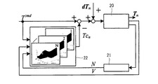
- the principal part schematic block diagram of the periodic disturbance automatic suppression apparatus which shows the Example of this invention. Compensation table data generation explanatory drawing.
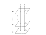
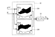
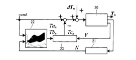
- the block diagram of a compensation table The principal part schematic block diagram of the periodic disturbance automatic suppression apparatus which shows another Example. Compensation table data generation explanatory drawing.
- the principal part schematic block diagram of the periodic disturbance automatic suppression apparatus which shows another Example. Compensation table data generation explanatory drawing.
- the principal part schematic block diagram of another periodic disturbance automatic suppression apparatus The principal part schematic block diagram of the other period disturbance automatic suppression apparatus.
- the principal part schematic block diagram of the periodic disturbance automatic suppression apparatus which shows another Example.
- the block diagram of the learning system of the periodic disturbance automatic suppression apparatus which shows another Example.
- the block diagram of the learning system of the conventional periodic disturbance automatic suppression apparatus The block diagram of the conventional periodic disturbance automatic suppression apparatus.
- the present invention tabulates a compensation value for suppressing torque pulsation in advance in a compensation table, and controls the torque pulsation for each frequency component by the torque compensation value based on the input torque setting value and the detected rotational speed.
- the main power supply voltage is detected and inputted to a compensation table corresponding to the voltage, and a torque compensation value depending on the voltage is outputted to the compensation table for compensation, which will be described in detail below with reference to the drawings.
- FIG. 1 is a schematic configuration diagram showing a first embodiment of the present invention.
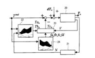
- the control target 20 includes an inverter main circuit, a motor, and the like, and the rotational speed detection unit 21 detects the rotational speed N of the motor. Further, the voltage V is detected from the DC circuit of the inverter and is input to the compensation table 22 together with the rotational speed N. Compensation table 22 has a 1 ⁇ n pieces of the plurality of compensation tables, torque setpoint T cmd corresponding to Tref * shown in FIG. 14 is also input.
- the torque set value Tcmd and the rotation speed N are changed using the system shown in FIG. 13, and a compensation value for vibration suppression at that point is acquired. This is repeated at all points in the assumed operating range to obtain experimental data. Finally, the compensation table is generated by performing interpolation processing as it is or partially from all the experimental data.
- a torque compensation value Tc n by compensation table 22 DC voltage V of the inverter main power be added to the variables.
- compensation table data of (torque i point ⁇ rotational speed j point) ⁇ main voltage k point as shown in FIG. 2 is generated, and this is mounted on a periodic disturbance automatic suppression device to perform feedforward control. That is, the torque compensation value Tc n determined by a characteristic such as lines l1 or l2 on the basis of the detected voltage V.
- FIG. 3 shows a detailed view of the compensation table.
- Each of the n compensation tables has a real part compensation table 22A and an imaginary part compensation table 22B.
- the torque set value Tcmd and the rotational speed N are input to the torque compensation values Ta and Tb corresponding to the input values, respectively. It is selected, the sum of the real value Ta n and imaginary values JTB n is torque compensation value Tc n in the compensation value correcting unit (adder unit) 23.
- the subtraction unit torque compensation value Tc n of the vibration suppression a deviation between the torque set value T cmd output, vibration suppression is performed sum of the deviation and cycle disturbance dTn is inputted to the controlled object 20.
- a controller that generates a control command value at the upper level has a controller that suppresses vibration by a vibration suppression compensation table acquired using a periodic disturbance observer for a control target that generates periodic disturbance.
- the compensation of the main power supply voltage due to load changes as a compensation table with torque, rotation speed, and main power supply voltage as parameters makes it possible to suppress the torque ripple generated by the motor control device itself, especially when the main power supply is a battery.
- a highly accurate current control response is possible.
- FIG. 4 shows the second embodiment, which is an example in which the compensation value fluctuation amount depends only on the voltage fluctuation of the main power source to be controlled.
- the compensation table 22 may be only one set of the real part compensation table 22A and the imaginary part compensation table 22B as shown in FIG. ⁇ It is not necessary to acquire data including the rotation speed.
- the main voltage V is directly input to the compensation value correction unit 23 with respect to the compensation table in which the main voltage V is acquired as a nominal main voltage, and calculation is performed using a specific table or a proportional expression that depends only on the voltage. it allows eliminating the memory for storage compensation table, the torque compensation value Tc n obtained by the compensation characteristic as shown in FIG. 5 on the basis of the detected voltage V.
- the compensation value correcting unit 23 the calculation of the torque compensation value Tc n when corrected by a first order polynomial is performed by (1).
- the compensation table 22 torque setpoint from T cmd the detected torque Ta n corresponding to the current rotational speed N, the Tb n is selected, the compensation value correcting unit 23 (1) computation of the expression is performed the torque compensation value Tc n is calculated Te.
- Torque compensation value Tc n is the difference calculation performed by the deviation between the torque setting T cmd determined at the subtraction unit, An added value of the deviation and the periodic disturbance dTn is input to the controlled object 20 to suppress vibration.
- the main power supply voltage fluctuation due to a load change is suppressed by using a formula or a table with the main power supply voltage as a parameter,
- the effect of saving the memory for storing the compensation table can be obtained.
- Others have the same effects as those of the first embodiment.
- FIG. 6 shows a third embodiment.
- the difference from FIG. 4 is that a coefficient correction table 24 is provided.
- the coefficient correction table 24 is configured to receive the torque set value Tcmd and the detected rotational speed N, and output the coefficients fa, fb, fc, and fd corresponding to the input values to the compensation value correction unit 23, thereby compensating the compensation value.
- the correction unit 23 corrects the compensation value of the nominal compensation table with an n-order polynomial.
- the polynomial coefficient at this time is corrected by a table or formula depending on the torque / rotation speed, and parameters of the correction formula are calculated by experiment or analysis.
- FIG. 7 shows the embodiment of the compensation table data generated, the characteristic torque compensation value Tc n such as lines l1 or l2 corresponds to the voltage obtained.
- the calculation of the torque compensation value Tc n when the compensation value correcting unit 23 to implement the correction at first order polynomial is performed based on equation (2).
- FIG. 8 is the coefficient correction table 24 shows an example of the case of inputting only the torque setpoint T cmd, the calculation of the torque compensation value Tc n in a first order polynomial in the compensation value correcting portion 23 in this case is (3 ) Based on the formula.
- Tc n Ta n ⁇ ⁇ fa (T cmd) ⁇ V + fb (T cmd) ⁇ + jTb n ⁇ ⁇ fc (T cmd) ⁇ V + fd (T cmd ) ⁇ (3) Further, FIG.
- Tc n Ta n ⁇ ⁇ fa (N) ⁇ V + fb (N) ⁇ + jTb n ⁇ ⁇ fc (N) ⁇ V + fd (N) ⁇ .
- (4) Therefore, according to the third embodiment, by compensating the compensation value of the compensation table with an nth-order polynomial, it is possible to perform compensation for vibration suppression that is further expanded as compared with the compensation of the second embodiment.
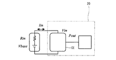
- the controlled object 20 has voltage control means CE capable of voltage control, and the applied voltage Vin is expressed by the relationship of the expression (5) ( 6) Control based on the equation.
- Rin main power supply internal resistance
- Vbas main power supply internal voltage
- Iin main power supply current
- Vin device applied voltage
- Pout device output voltage
- ⁇ motor rotation speed
- the torque / speed command value is input to the voltage calculation unit 6
- the voltage Vin is calculated based on the equation (6) from the relationship of the equation (5)
- the variable voltage control unit 7 Controls the DC voltage Vdc of the inverter 1 based on the voltage Vin.
- the rotational speed and torque detection value at this time are stored in the torque pulsation suppressing means of the controller 5 as in FIG. This is repeated at all points in the assumed operating range including instantaneous load current fluctuations to obtain experimental data.
- the compensation table is generated by performing interpolation processing as it is or partially from all the experimental data.
- FIG. 11 is used as the vibration suppression control device using the compensation table in this embodiment, and only the torque set value Tcmd and the rotational speed N are input to the compensation table 22.
- the nominal compensation table is generated by setting the voltage command of the voltage control means CE of the main power source to Vin, and for each operating point, the voltage control means CE adjusts the voltage according to the torque / rotation command value at that time, and the torque by the compensation table 22 is generated. Generate a compensation value. Therefore, the obtained compensation table 22 is a table that takes into account the voltage fluctuation in advance, and by mounting this on the periodic disturbance automatic suppression device, it is possible to achieve vibration suppression without error for voltage fluctuation during operation. .
- the vibration can be suppressed with high accuracy without changing the memory amount of the control device.
- the compensation table used for performing the feedforward control is also compensated for the main power supply voltage fluctuation due to the load change. Even if it occurs, it is possible to perform highly accurate vibration suppression control.
Landscapes
- Engineering & Computer Science (AREA)
- Power Engineering (AREA)
- Transportation (AREA)
- Mechanical Engineering (AREA)
- Control Of Electric Motors In General (AREA)
- Control Of Ac Motors In General (AREA)
Abstract
Description
iq0 *にトルク脈動補償電流iqc*を重畳して電流ベクトル制御指令値とする。
コントローラ5は、トルクリプル抑制制御手段5Aと学習手段5Bを搭載し、トルク脈動抑制に必要な補償電流をフーリェ係数テーブルとしてメモリに保存する。
前記補償テーブルを電圧毎に複数設け、前記制御対象の主電源電圧を検出して電圧に対応する補償テーブルに入力し、補償テーブルに対して主電源電圧の変動値に連動したトルク補償値を出力するよう構成したことを特徴としたものである。
前記補償テーブルは実数部を補正する実部補償テーブルと虚数部を補正する虚部補償テーブルを備え、且つ前記制御対象の主電源電圧の検出値Vを入力する補償値補正部を設け、この補償値補正部で、前記実部補償テーブルの出力Taと虚部補償テーブルjTbとの和によるトルク補償値Tcnを主電源電圧の変動値に連動した特定のテーブルもしくは比例式により補正を行うよう構成したことを特徴としたものである。
Tcn=Tan・(a・V+b)+jTbn・(c・V+d)
ただし、添え字のnはn次成分を示す。
Tcn=Tan・{fa(Tcmd,N)・V+fb(Tcmd,N)}+jTbn・{fc(Tcmd,N)・V+fd(Tcmd,N)}
ただし、fa~fdは関数、Tcmdはトルク設定値、Nは回転数、Vは電圧検出値、nはn次成分
本発明の他の観点によれば、トルク設定値を入力してトルク依存した多項式用の係数を出力する係数テーブルを設け、この係数テーブルの出力を前記補償値補正部に入力し、この補償値補正部でトルクに依存したテーブルもしくは比例式によりトルク補償値Tcnの補正を行うよう構成したことを特徴としたものである。
Tcn=Tan・{fa(Tcmd)・V+fb(Tcmd)}+jTbn・{fc(Tcmd)・V+
fd(Tcmd)}
ただし、fa~fdは関数、Tcmdはトルク設定値、Vは電圧検出値、nはn次成分
本発明の他の観点によれば、前記制御対象の回転数検出値を入力して回転数に依存した多項式用の係数を出力する係数テーブルを設け、この係数テーブルの出力を前記補償値補正部に入力し、この補償値補正部で回転数に依存したテーブルもしくは比例式によりトルク補償値Tcnの補正を行うよう構成したことを特徴としたものである。
Tcn=Tan・{fa(N)・V+fb(N)}+jTbn・{fc(N)・V+fd(N)}
ただし、fa~fdは関数、Nは回転数、Vは電圧検出値、nはn次成分
本発明の更に他の観点によれば、制御対象のトルク脈動周波数成分を抽出してトルク脈動を抑制するための補償値を予め補償テーブルにテーブル化し、入力したトルク設定値と検出された制御対象の回転数によってトルク補償値を求め、求まったトルク補償値とトルク設定値の偏差分を制御対象に入力して周波数成分毎のトルク脈動を抑制するものにおいて、
前記制御対象は、主電源をバッテリとし、電圧を可変制御可能とした電圧制御手段を備え、前記補償テーブルは、予め電圧制御手段による動作点毎の調整された印過電圧による補正値によって生成された補償テーブルであることを特徴としたものである。
周波数成分毎のトルク脈動を抑制するとき、制御対象の主電源電圧を検出して電圧に対応する補償テーブルに入力し、補償テーブルに対して電圧に依存したトルク補償値を出力して補償するもので、図に基づいて以下に詳述する。
Tcn=Tan・(a・V+b)+jTbn・(c・V+d)…… (1)
テーブル参照時には、補償テーブル22からトルク設定値Tcmdと検出された現在の回転数Nに対応したトルクTan,Tbnが選択され、補償値補正部23において(1)式の演算が行われてトルク補償値Tcnが算出される。トルク補償値Tcnは、減算部においてトルク設定値Tcmdとの差演算が行われて偏差が求められ、
この偏差と周期外乱dTnの加算値が制御対象20に入力されて振動抑制が行われる。
Tcn=Tan・{fa(Tcmd,N)・V+fb(Tcmd,N)}+jTbn・{fc(Tcmd,N)・V+fd(Tcmd,N)} …… (2)
図8は係数補正テーブル24にはトルク設定値Tcmdのみを入力する場合の例を示したもので、この場合の補償値補正部23における一次多項式でのトルク補償値Tcnの算出は(3)式に基づいて行われる。
Tcn=Tan・{fa(Tcmd)・V+fb(Tcmd)}+jTbn・{fc(Tcmd)・V+
fd(Tcmd)} …… (3)
また、図9は係数補正テーブル24には検出された回転数Nのみを入力する場合の例を示したもので、この場合の補償値補正部23における一次多項式でのトルク補償値Tcnの算出は(4)式に基づいて行われる。
Tcn=Tan・{fa(N)・V+fb(N)}+jTbn・{fc(N)・V+fd(N)}……… (4)
したがって、この実施例3によれば、補償テーブルの補償値をn次多項式で補正することにより、実施例2の補償よりもさらに拡張された振動抑制のための補償が可能となるものである。
Vin=Vbas-Iin・Rin
Iin=Pout/Vin
Pout=ω・Tcmd …… (5)

補償テーブル22でのデータ取得方法としては図12で示すシステムが用いられ、トルク/速度指令値が電圧演算部6に入力されて(5)式の関係から(6)式に基づいて電圧Vinを演算し、可変電圧制御部7は電圧Vinに基づいてインバータ1の直流電圧Vdcを制御する。このときの回転数とトルク検出値を図13と同様にコントローラ5のトルク脈動抑制手段に保存する。これを瞬間的な負荷電流変動を含む想定動作範囲の全点で繰返し行なって実験データを取得する。最終的に全実験データから、そのまま若しくは部分的に補間処理を行って補償テーブルを生成する。
Claims (10)
- 制御対象のトルク脈動周波数成分を抽出してトルク脈動を抑制するための補償値を予め補償テーブルにテーブル化し、入力したトルク設定値と検出された回転数によってトルク補償値を求め、求まったトルク補償値とトルク設定値の偏差分を制御対象に入力して周波数成分毎のトルク脈動を抑制するものにおいて、
前記補償テーブルを複数の補償テーブルとし、前記制御対象の主電源電圧を検出して電圧に対応する補償テーブルに入力し、補償テーブルに対して主電源電圧の変動値に連動したトルク補償値を出力するよう構成したことを特徴とする周期外乱自動抑制装置。 - 制御対象のトルク脈動周波数成分を抽出してトルク脈動を抑制するための補償値を予め補償テーブルにテーブル化し、入力したトルク設定値と検出された制御対象の回転数によってトルク補償値を求め、求まったトルク補償値とトルク設定値の偏差分を制御対象に入力して周波数成分毎のトルク脈動を抑制するものにおいて、
前記補償テーブルは実数部を補正する実部補償テーブルと虚数部を補正する虚部補償テーブルを備え、且つ前記制御対象の主電源電圧の検出値Vを入力する補償値補正部を設け、この補償値補正部で、前記実部補償テーブルの出力Taと虚部補償テーブルjTbとの和によるトルク補償値Tcnを主電源電圧の変動値に連動した特定のテーブルもしくは比例式により補正を行うよう構成したことを特徴とする周期外乱自動抑制装置。 - 前記トルク補償値Tcnを補正するための比例式は、次式による一次多項式で補正することを特徴とする請求項2記載の周期外乱自動抑制装置。
Tcn=Tan・(a・V+b)+jTbn・(c・V+d)
ただし、添え字のnはn次成分を示す。 - トルク設定値と制御対象の回転数検出値を入力してトルク・回転数に依存した多項式用の係数を出力する係数テーブルを設け、この係数テーブルの出力を前記補償値補正部に入力し、この補償値補正部でトルク・回転数に依存したテーブルもしくは比例式によりトルク補償値Tcnの補正を行うよう構成したことを特徴とする請求項2記載の周期外乱自動抑制装置。
- 前記トルク補償値Tcnを補正するための比例式は、次式による一次多項式で補正することを特徴とする請求項4記載の周期外乱自動抑制装置。
Tcn=Tan・{fa(Tcmd,N)・V+fb(Tcmd,N)}+jTbn・{fc(Tcmd,N)・V+fd(Tcmd,N)}
ただし、fa~fdは係数、Tcmdはトルク設定値、Nは回転数、Vは電圧検出値、nはn次成分 - トルク設定値を入力してトルク依存した多項式用の係数を出力する係数テーブルを設け、この係数テーブルの出力を前記補償値補正部に入力し、この補償値補正部でトルクに依存したテーブルもしくは比例式によりトルク補償値Tcnの補正を行うよう構成したことを特徴とする請求項2記載の周期外乱自動抑制装置。
- 前記トルク補償値Tcnを補正するための比例式は、次式による一次多項式で補正することを特徴とする請求項6記載の周期外乱自動抑制装置。
Tcn=Tan・{fa(Tcmd)・V+fb(Tcmd)}+jTbn・{fc(Tcmd)・V+
fd(Tcmd)}
ただし、fa~fdは係数、Tcmdはトルク設定値、Vは電圧検出値、nはn次成分 - 前記制御対象の回転数検出値を入力して回転数に依存した多項式用の係数を出力する係数テーブルを設け、この係数テーブルの出力を前記補償値補正部に入力し、この補償値補正部で回転数に依存したテーブルもしくは比例式によりトルク補償値Tcnの補正を行うよう構成したことを特徴とする請求項2記載の周期外乱自動抑制装置。
- 前記トルク補償値Tcnを補正するための比例式は、次式による一次多項式で補正することを特徴とする請求項8記載の周期外乱自動抑制装置。
Tcn=Tan・{fa(N)・V+fb(N)}+jTbn・{fc(N)・V+fd(N)}
ただし、fa~fdは係数、Nは回転数、Vは電圧検出値、nはn次成分 - 制御対象のトルク脈動周波数成分を抽出してトルク脈動を抑制するための補償値を予め補償テーブルにテーブル化し、入力したトルク設定値と検出された制御対象の回転数によってトルク補償値を求め、求まったトルク補償値とトルク設定値の偏差分を制御対象に入力して周波数成分毎のトルク脈動を抑制するものにおいて、
前記制御対象は、主電源をバッテリとし、電圧を可変制御可能とした電圧制御手段を備え、前記補償テーブルは、予め電圧制御手段による動作点毎の調整された印過電圧による補正値によって生成された補償テーブルであることを特徴とした周期外乱自動抑制装置。
Priority Applications (4)
| Application Number | Priority Date | Filing Date | Title |
|---|---|---|---|
| KR1020157036548A KR20160016895A (ko) | 2013-06-10 | 2014-06-10 | 주기성 교란의 자동 억제장치 |
| JP2015504780A JP5800108B2 (ja) | 2013-06-10 | 2014-06-10 | 周期外乱自動抑制装置 |
| US14/896,845 US9729094B2 (en) | 2013-06-10 | 2014-06-10 | Automatic suppression device for cyclic disturbance |
| CN201480033035.3A CN105324930B (zh) | 2013-06-10 | 2014-06-10 | 周期性干扰自动抑制装置 |
Applications Claiming Priority (2)
| Application Number | Priority Date | Filing Date | Title |
|---|---|---|---|
| JP2013-121466 | 2013-06-10 | ||
| JP2013121466 | 2013-06-10 |
Publications (1)
| Publication Number | Publication Date |
|---|---|
| WO2014199994A1 true WO2014199994A1 (ja) | 2014-12-18 |
Family
ID=52022286
Family Applications (1)
| Application Number | Title | Priority Date | Filing Date |
|---|---|---|---|
| PCT/JP2014/065374 Ceased WO2014199994A1 (ja) | 2013-06-10 | 2014-06-10 | 周期外乱自動抑制装置 |
Country Status (5)
| Country | Link |
|---|---|
| US (1) | US9729094B2 (ja) |
| JP (1) | JP5800108B2 (ja) |
| KR (1) | KR20160016895A (ja) |
| CN (1) | CN105324930B (ja) |
| WO (1) | WO2014199994A1 (ja) |
Families Citing this family (12)
| Publication number | Priority date | Publication date | Assignee | Title |
|---|---|---|---|---|
| US10666180B2 (en) * | 2015-07-22 | 2020-05-26 | Texas Instruments Incorporated | Adaptive torque disturbance cancellation for electric motors |
| JP6149948B1 (ja) * | 2016-01-07 | 2017-06-21 | 株式会社明電舎 | 供試体特性推定方法及び供試体特性推定装置 |
| CN105577059B (zh) * | 2016-01-19 | 2018-05-25 | 南京航空航天大学 | 一种船用异步电机系统的噪声抑制方法 |
| CN106688175B (zh) * | 2016-03-01 | 2020-08-04 | 深圳市大疆创新科技有限公司 | 电机的控制方法、装置及系统 |
| JP6197923B1 (ja) * | 2016-06-27 | 2017-09-20 | 株式会社明電舎 | 制御システム |
| JP6513161B1 (ja) * | 2017-10-20 | 2019-05-15 | 三菱電機株式会社 | 回転電機の制御装置 |
| JP6645525B2 (ja) * | 2018-02-23 | 2020-02-14 | 株式会社明電舎 | 試験システムの制御装置 |
| CN108809185B (zh) * | 2018-06-27 | 2020-05-05 | 安徽江淮汽车集团股份有限公司 | 一种电动汽车的电机扭矩控制的方法及系统 |
| US11611305B2 (en) * | 2020-10-23 | 2023-03-21 | GM Global Technology Operations LLC | Bandwidth-partitioning harmonic regulation for improved acoustic behavior of an electric drive system |
| CN112968652B (zh) * | 2021-02-01 | 2025-10-24 | 国奥科技(深圳)有限公司 | 一种直线电机的控制方法、装置、设备以及存储介质 |
| IT202100018689A1 (it) * | 2021-07-15 | 2023-01-15 | Ferrari Spa | Procedimento ed apparato per controllare un motore elettrico |
| CN116460853B (zh) * | 2023-05-17 | 2024-06-04 | 苏州艾利特机器人有限公司 | 柔性关节速度脉动补偿方法、装置、系统及存储介质 |
Citations (4)
| Publication number | Priority date | Publication date | Assignee | Title |
|---|---|---|---|---|
| JP2000228892A (ja) * | 1999-02-08 | 2000-08-15 | Hitachi Ltd | 同期電動機の制御装置 |
| JP2007274782A (ja) * | 2006-03-30 | 2007-10-18 | Aisin Aw Co Ltd | 電動駆動制御装置及び電動駆動制御方法 |
| JP2011050118A (ja) * | 2009-08-25 | 2011-03-10 | Meidensha Corp | 電動機のトルク脈動抑制システム |
| JP2013085330A (ja) * | 2011-10-06 | 2013-05-09 | Mitsubishi Heavy Ind Ltd | モータ制御装置およびトルク値取得方法 |
Family Cites Families (4)
| Publication number | Priority date | Publication date | Assignee | Title |
|---|---|---|---|---|
| WO2000019288A1 (en) * | 1998-09-28 | 2000-04-06 | Kabushiki Kaisha Yaskawa Denki | Position controller |
| KR101361869B1 (ko) * | 2010-05-20 | 2014-02-12 | 미쓰비시덴키 가부시키가이샤 | 모터 제어 장치 |
| JP5273575B2 (ja) * | 2011-09-01 | 2013-08-28 | 株式会社安川電機 | 電動機制御装置 |
| JP5839510B2 (ja) * | 2011-10-24 | 2016-01-06 | 株式会社ハーモニック・ドライブ・システムズ | 波動歯車装置を備えたアクチュエータの位置決め制御システム |
-
2014
- 2014-06-10 US US14/896,845 patent/US9729094B2/en not_active Expired - Fee Related
- 2014-06-10 KR KR1020157036548A patent/KR20160016895A/ko not_active Ceased
- 2014-06-10 CN CN201480033035.3A patent/CN105324930B/zh not_active Expired - Fee Related
- 2014-06-10 JP JP2015504780A patent/JP5800108B2/ja active Active
- 2014-06-10 WO PCT/JP2014/065374 patent/WO2014199994A1/ja not_active Ceased
Patent Citations (4)
| Publication number | Priority date | Publication date | Assignee | Title |
|---|---|---|---|---|
| JP2000228892A (ja) * | 1999-02-08 | 2000-08-15 | Hitachi Ltd | 同期電動機の制御装置 |
| JP2007274782A (ja) * | 2006-03-30 | 2007-10-18 | Aisin Aw Co Ltd | 電動駆動制御装置及び電動駆動制御方法 |
| JP2011050118A (ja) * | 2009-08-25 | 2011-03-10 | Meidensha Corp | 電動機のトルク脈動抑制システム |
| JP2013085330A (ja) * | 2011-10-06 | 2013-05-09 | Mitsubishi Heavy Ind Ltd | モータ制御装置およびトルク値取得方法 |
Also Published As
| Publication number | Publication date |
|---|---|
| US20160134218A1 (en) | 2016-05-12 |
| JPWO2014199994A1 (ja) | 2017-02-23 |
| CN105324930B (zh) | 2017-09-12 |
| KR20160016895A (ko) | 2016-02-15 |
| US9729094B2 (en) | 2017-08-08 |
| JP5800108B2 (ja) | 2015-10-28 |
| CN105324930A (zh) | 2016-02-10 |
Similar Documents
| Publication | Publication Date | Title |
|---|---|---|
| JP5800108B2 (ja) | 周期外乱自動抑制装置 | |
| JP5929863B2 (ja) | 制御装置 | |
| JP5434368B2 (ja) | 電動機のトルク脈動抑制システム | |
| JP5326429B2 (ja) | 電動機の脈動抑制装置 | |
| JP5839111B2 (ja) | 三相交流誘導モータの制御装置及び三相交流誘導モータの制御方法 | |
| JP5877733B2 (ja) | 電動モータの制御装置 | |
| JPWO2010024195A1 (ja) | 電動機の外乱抑圧装置および外乱抑圧方法 | |
| JP6667076B2 (ja) | モータ制御装置、およびこのモータ制御装置におけるトルク定数の補正方法 | |
| JP5488043B2 (ja) | モータのトルク制御装置 | |
| WO2012133799A1 (ja) | 電動機の脈動抑制装置および電動機の脈動抑制方法 | |
| WO2014088054A1 (ja) | 周期外乱自動抑制装置 | |
| JP5644203B2 (ja) | 回転電気機械のトルクリプル抑制制御装置および制御方法 | |
| JP6504795B2 (ja) | トルクリップル抑制装置及びトルクリップル抑制方法 | |
| JP2011050178A (ja) | モータ制御装置及び発電機制御装置 | |
| JP7035818B2 (ja) | 巻線界磁型同期モータの制御方法、及び、制御装置 | |
| JP2019221105A (ja) | モータ駆動装置 | |
| JP6183554B2 (ja) | 周期外乱自動抑制装置 | |
| JP3920750B2 (ja) | Dcブラシレスモータの制御装置 | |
| JP4201676B2 (ja) | モータ制御装置 | |
| KR102621423B1 (ko) | 모터 구동 장치 및 그것을 사용한 공기 조화기의 실외기 | |
| JP5262267B2 (ja) | 三相交流モータの駆動装置 | |
| JP6409313B2 (ja) | 周期外乱自動抑制装置 | |
| WO2015105093A1 (ja) | 電動機の制御装置 | |
| WO2020152785A1 (ja) | モータ制御方法、及び、モータ制御装置 | |
| JP2009124783A (ja) | 同期電動機の温度補償装置 |
Legal Events
| Date | Code | Title | Description |
|---|---|---|---|
| WWE | Wipo information: entry into national phase |
Ref document number: 201480033035.3 Country of ref document: CN |
|
| ENP | Entry into the national phase |
Ref document number: 2015504780 Country of ref document: JP Kind code of ref document: A |
|
| 121 | Ep: the epo has been informed by wipo that ep was designated in this application |
Ref document number: 14811452 Country of ref document: EP Kind code of ref document: A1 |
|
| WWE | Wipo information: entry into national phase |
Ref document number: 14896845 Country of ref document: US |
|
| NENP | Non-entry into the national phase |
Ref country code: DE |
|
| ENP | Entry into the national phase |
Ref document number: 20157036548 Country of ref document: KR Kind code of ref document: A |
|
| 122 | Ep: pct application non-entry in european phase |
Ref document number: 14811452 Country of ref document: EP Kind code of ref document: A1 |